

Rittal DK 7856.540, DK 7856.530, DK 7856.550 Assembly, Installation And Operation
EN Switched Power Distribution Unit
DK 7856.530 / 540 / 550
Assembly, Installation and Operation
A40195 01 IT 74

2
Switched Power Distribution Unit
Microsoft Windows is a registered trademark of Microsoft Corporation.
Acrobat Reader is a registered trademark of Adobe Systems Incorporated.

Table of Contents 1
Switched Power Distribution Unit
3
EN
1 Table of Contents
1 Table of Contents ..............................3
2 Documentation Notes .......................4
3 Safety Instructions ............................4
3.1
Safety Precautions.......................... 5
3.2
Life-Support Policy.......................... 6
4 Product Introduction.........................7
4.1
Technical Equipment....................... 7
4.2
Power Supply.................................. 8
4.3
Usable Sensors............................... 8
4.4
Accessories..................................... 8
4.5
Optional Accessories ...................... 8
5
Mounting ............................................9
5.1
Mounting the PDU........................... 9
5.2
Expansion Module........................... 9
6 Installing...........................................10
6.1
Security advices............................ 10
6.2
Connecting to the Power Source .. 10
6.3
Connecting Devices...................... 10
6.4
Connecting to the Unit ..................10
7 Operations........................................11
7.1
Interfaces ...................................... 11
7.1.1 Outlet Naming and Grouping ........ 11
7.1.2 Usernames and Passwords.......... 11
7.2
HTML Interface ............................. 12
7.2.1 Logging In ..................................... 13
7.2.2 Power Monitoring .......................... 13
7.2.3 Environmental Monitoring ............. 14
7.2.4 Configuration................................. 14
7.2.5 Tools ............................................. 24
7.3
Command Line Interface............... 24
7.3.1 Administration Commands............ 31
7.3.2 System Administration .................. 39
8 Advanced Operations .....................49
8.1
SSL ............................................... 49
8.1.1 Setting up SSL Support ................49
8.2
SSH............................................... 49
8.3
SNMP/Thresholds......................... 50
8.4
LDAP............................................. 56
8.4.1 Configuring LDAP Groups ............61
8.4.2 LDAP Technical Specifications..... 64
8.4.3 LDAPS Client Specifications......... 65
8.5
TACACS+...................................... 65
8.5.1 TACACS+ Privilege Levels ........... 67
8.6
Logging ......................................... 69
8.6.1 Email..............................................70
8.7
Upload/Download...........................72
9 Appendices...................................... 73
9.1
Resetting to Factory Defaults ........73
9.2
Uploading Firmware.......................74
10 Technical Specifications ................ 74
10.1 Technical Data...............................74
10.2 Data Connections ..........................75
10.3 LED Indicators ...............................75
10.4 Regulatory Compliance..................76
11 Maintenance and Cleaning............. 77
11.1 Cleaning.........................................77
12 Customer Service ........................... 77
Documentation Notes 2
4
Switched Power Distribution Unit
EN
2 Documentation Notes
The audience for this guide is the technical specialist familiar with the assembly, installation and
operation of the Switched PDU System.
You should read this operating guide prior to
commissioning and store the guide so it is readily
accessible for subsequent use.
Rittal cannot accept any liability for damage and
operational malfunctions that result from the nonobservance of this guide.
Retention of Documents
This guide and all associated documents are part
of the product. They must be given to the operator
of the unit and must be stored so they are available when needed.
Symbols Used
The following safety and other notes are used in
this guide:
Symbol for handling instructions:
•
This bullet point indicates that you should
perform an action.
Safety and other notes:
Danger!
Immediate danger to health and life!
Warning!
Possible danger for the product and
the environment!
Note!
Useful information and special features.
3 Safety Instructions
1. Assembly and installation of the Switched
PDU, in particular for wiring the enclosures
with mains power, may be performed only
by a trained electrician. Other tasks associated with the PDU, such as the assembly
and installation of system components with
tested standard connectors, and the operation and configuration of the PDU may be
performed only by instructed personnel.
2. Do not open the case, as there are no serviceable parts inside. Your warranty will be
void.
3. Do not try to repair the unit yourself; contact
your local supplier or your warranty will be
void.
4. If liquids are spilt onto the PDU or foreign
objects dropped into the unit, the warranty
will be null and void.
5. Do not install the PDU in an environment
with sparks, smoke or gas.
6. The PDU is designed to be installed and
commissioned in a sheltered, controlled environment as follows:
- Operating temperature 0-40°C and 5-
90% non-condensing humidity.
- Always avoid contact with direct
sunlight.
- Do not install the PDU in inflammable
or hazardous environment.
- Dusty, corrosive and salty envi-
ronments can do damage to the PDU.
- Install the PDU indoors as it is not de-
signed for installation outdoors.
7. Install the PDU away from objects that give
off excessive heat and areas that are excessively wet.
8. Always switch off the PDU when relocating
it.
9. Make sure that the AC main supply outlet is
correctly grounded.
10. Please ensure that the input voltage of the
PDU matches the utility supply voltage.
11. Observe the valid regulations for the electrical installation for the country in which the
unit is installed and operated, and the national regulations for accident prevention.
Also observe any company-internal regulations (work, operating and safety regulations).
Use only genuine or recommended parts and
accessories. The use of other parts can void the
liability for any resulting consequences.
Safety Instructions 3
Switched Power Distribution Unit
5
EN
3.1 Safety Precautions
This section contains important safety and regulatory information that should be reviewed before installing
and using the Switched Power Distribution Unit.
Only for installation and use
in a Restricted Access Location in accordance with the
following installation and use
instructions.
Seulement pour l’installation et
l’utilisation dans une Zone Interdite conformément aux installations et l’utilisation des
indications suivantes.
Nur zur Installation und Verwendung in einem Sicherheitsbereich gemäß den folgenden
Installations- und Verwendungsanleitungen.
This equipment is designed
to be installed on a dedicated
circuit.
Cet équipement est conçu à
être installé sur un circuit spécialisé.
Diese Ausrüstung ist zur Installation in einem festen Stromkreis vorgesehen.
Dedicated circuit must have
circuit breaker or fuse protection.
PDUs have been designed
without a master circuit
breaker or fuse to avoid becoming a single point of failure. It is the customer’s responsibility to provide adequate protection for the dedicated power circuit. Protection of capacity equal to the
current rating of the PDU
must be provided and must
meet all applicable codes and
regulations. In North America, protection must have a
10,000A interrupt capacity.
Le circuit spécialisé doit avoir
un disjoncteur ou une protection de fusible. PDUs ont été
conçus sans disjoncteur général ni fusible pour éviter que
cela devient un seul endroit de
panne. C’est la responsabilité
du client de fournir une protection adéquate pour le circuitalimentation spécialisé. Protection de capacité équivalant à la
puissance de l'équipement, et
respectant tous les codes et
normes applicables. Les disjoncteurs ou fusibles destinés à
l'installation en Amérique du
Nord doivent avoir une capacité d'interruption de 10.000 A.
Der feste Stromkreis muss mit
einem Schutzschalter oder
einem Sicherungsschutz versehen sein.
PDUs verfügt über keinen
Hauptschutzschalter bzw. über
keine Sicherung, damit kein
einzelner Fehlerpunkt entstehen kann. Der Kunde ist dafür
verantwortlich, den Stromkreis
sachgemäß zu schützen. Der
Kapazitätsschutz entspricht der
aktuellen Stromstärke der Geräte und muss alle relevanten
Codes und Bestimmungen
erfüllen. Für Installation in
Nordamerika müssen Ausschalter bzw. Sicherung über
10.000 A Unterbrechungskapazität verfügen.
The plug on the power supply
cord shall be installed near
the equipment and shall be
easily accessible.
La prise sur le cordon
d’alimentation sera installée
près de l’équipement et sera
facilement disponible.
Der Stecker des Netzkabels
muss in der Nähe der Ausrüstung installiert werden und
leicht zugänglich sein.
Installation Orientation:
PDUs are design to be installed in vertical orientation.
Installation Orientation : PDUs
sont conçues pour être installées dans une orientation verticale.
Installationsausrichtung: PDUs
sind zur vertikalen Installation
vorgesehen.
Always disconnect the power
supply cord before opening to
avoid electrical shock.
Toujours déconnecter le cordon d’alimentation avant
d’ouvrir pour éviter un choque
électrique.
Ziehen Sie vor dem Öffnen
immer das Netzkabel heraus,
um die Gefahr eines elektrischen Schlags zu vermeiden.
WARNING! High leakage
current! Earth connection is
essential before connecting
supply!
ATTENTION ! Haut fuite très
possible ! Une connection de
masse est essentielle avant de
connecter l’alimentation !
ACHTUNG! Hoher Ableitstrom!
Ein Erdungsanschluss ist vor
dem Einschalten der Stromzufuhr erforderlich!
WARNING!
Double Pole/Neutral Fusing
ATTENTION!
Double Pôle/Fusible sur le
Neutre
ACHTUNG!:
Zweipolige bzw. Neutralleiter-
Sicherung

Safety Instructions 3
6
Switched Power Distribution Unit
EN
3.2 Life-Support Policy
As a general policy, Rittal does not recommend
the use of any of its products in the following situations:
• life-support applications where failure or
malfunction of the Rittal product can be reasonably expected to cause failure of the lifesupport device or to significantly affect its
safety or effectiveness.
• direct patient care.
Rittal will not knowingly sell its products for use in
such applications unless it receives in writing assurances satisfactory to Rittal that:
• the risks of injury or damage have been
minimized,
• the customer assumes all such risks, and
• the liability of Rittal is adequately protected
under the circumstances.
The term life-support device includes but is not
limited to neonatal oxygen analyzers, nerve
stimulators (whether used for anaesthesia, pain
relief or other purposes), auto-transfusion devices, blood pumps, defibrillators, arrhythmia
detectors and alarms, pacemakers, haemodialysis systems, peritoneal dialysis systems, neonatal
ventilator incubators, ventilators (for adults or
infants), anaesthesia ventilators, infusion pumps,
and any other devices designated as “critical” by
the U.S. FDA.
Product Introduction 4
Switched Power Distribution Unit
7
EN
4 Product Introduction
The Switched Power Distributing Unit (Switched
PDU) is a compact Distribution Unit, which can be
mounted easy and quick into every server rack. It
featured several C13 Plugs and has a voltage
and current measurement module.
By using the Web-Interface you can configure and
switch every single plug in the cabinet.
If one or more values of the Unit crosses the determined thresholds level you decided, the information can be send via SNMP or email to several
positions, which you can describe.
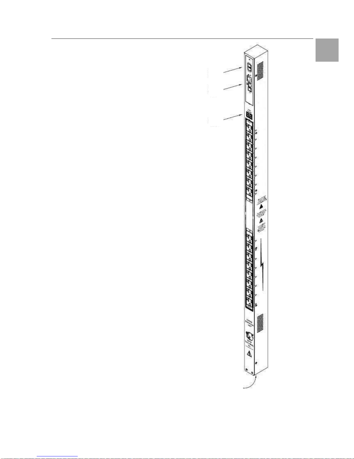
4.1 Technical Equipment
Figure 1 shows the technical equipment of the
Switched PDU.
1. Power inlet/cord
2. LED displays the current load for each infeed
3. RJ45 connectors for Serial (RS-232) and
Ethernet connection
4. Mini RJ-12 connectors for sensors
A number is printed above each outlet. These
numbers may be used in commands that require
an outlet name.
Abb. 1 Technical Equipment of the PDU
4
3
2
1
Product Introduction 4
8
Switched Power Distribution Unit
EN
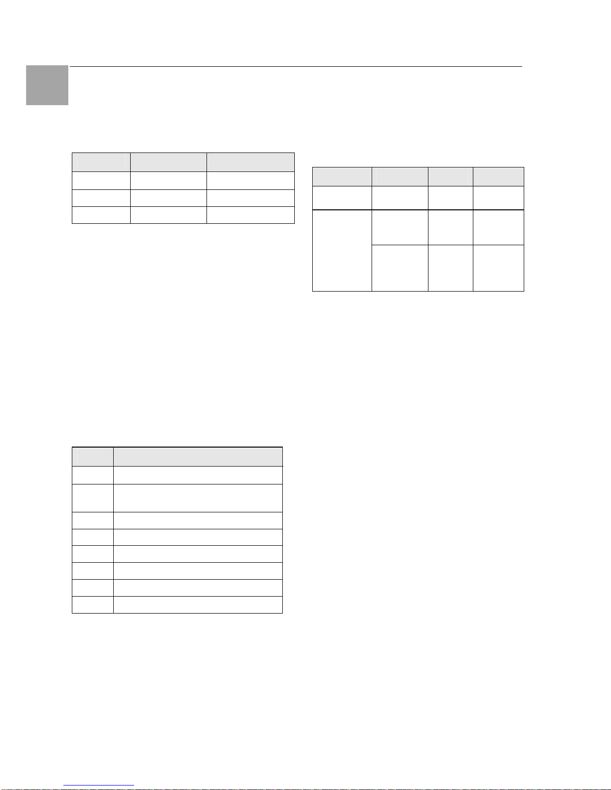
4.2 Power Supply
The Switched PDU is powered with the included
Connection Plug. The used Voltage depends of
the model, which is used.
DK-Nr.
Plug Power Supply
7856.530 1-phase
230V / 50 – 60 Hz
7856.540 3-phase 400V / 50 – 60 Hz
7856.550 2 x 1-phase 230V / 50 – 60 Hz
Tab. 1 Power Supply
4.3 Usable Sensors
The Switched PDU has two Mini RJ-11 T/H-Ports,
which can be used for several Sensors.
Connect the mini RJ-11 Plug from the sensor to
the T/H-Port on the PDU.
4.4 Accessories
Before installing your Switched PDU, refer to the
following lists to ensure that you have all the
items shipped with the unit as well as all other
items required for proper installation.
• Look for obvious damages on the package
Value Name
1 Switched PDU
1
Connection Cable 3 m (1-phase / 3phase, depends on model)
1
RJ45-/RJ45 - Cross cable
1
RJ45-/DB9F-Adapter for serial interface
1
RJ12-/RJ12 - Cross cable
1
Clips for Outputs
1 Mounting material
1 Instruction Manual
Tab. 2
Materials provided
4.5 Optional Accessories
Depending on the application it can be necessary
to order some optional accessories. Rittal offers
the following accessories for the Switched PDU:
Accessories Name Devices DK - Nr.
Expansion
Module
Slave Module - On request
C13/C14
0,5 m
2 7856.014
Server con-
nection plug
extension
cord
1,5 m
1 7200.215
Tab. 3 Optional Accessories
Mounting 5
Switched Power Distribution Unit
9
EN
5 Mounting
The included installation set allows the mounting
of the unit on the cabinet frame and in 800 mm
Cabinets also on the side of the 19-inch level.
Mounting hardware:
• Two removable flanges with four M4 screws
• Two mounting L-brackets with nut plates, four
sets of screws and washers
• Optional button mounts
Required Items:
• Flathead and Phillips screwdrivers
• Screws, washers and nuts to attach the PDU to
your rack
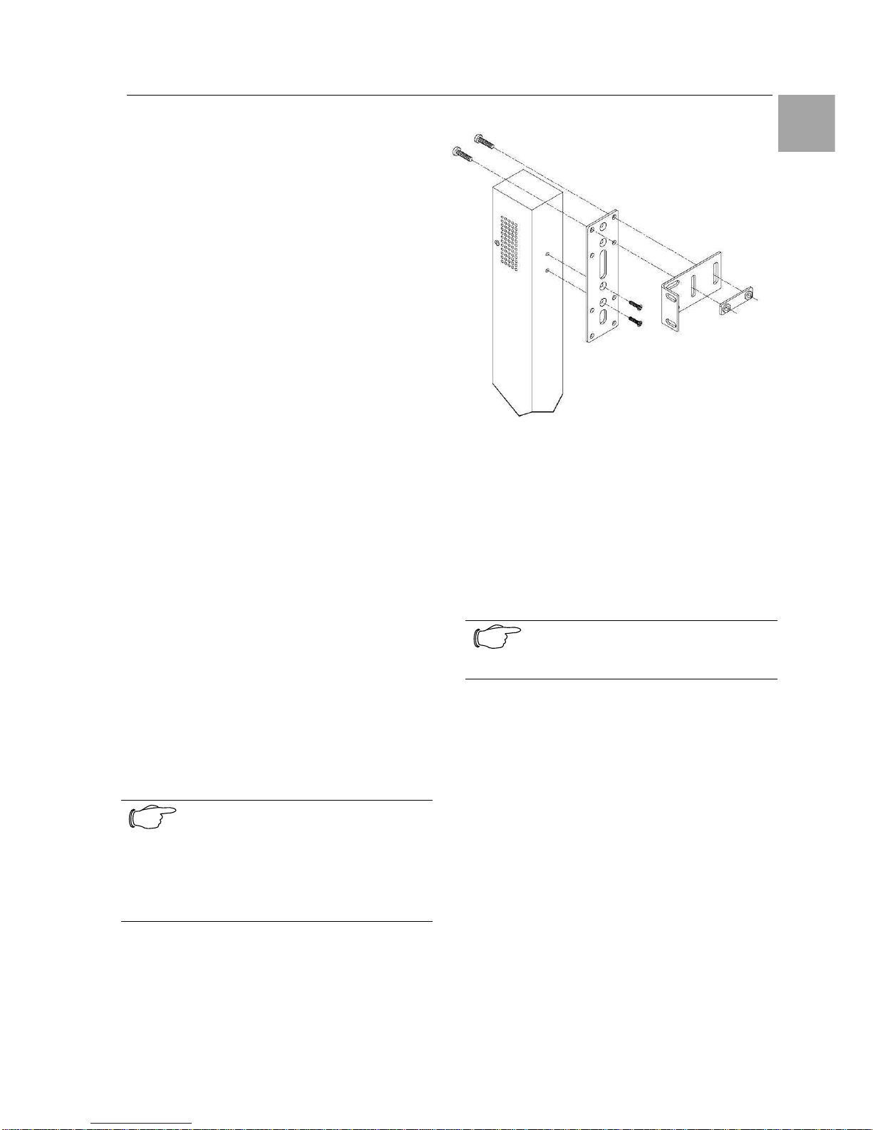
5.1 Mounting the PDU
The mounting steps are shown in figure 2.
1. Attach the removable flanges to the mount
points on the rear of the enclosure using M4
screws.
2. Attach the mounting L-brackets to the flanges
with the supplied screws, washers and nut
plates. The slots allow about 1½ inches of
vertical adaptability.
3. Attach the top and bottom brackets to your
rack.
Optionally, the supplied button mounts may be
used for mounting the PDU into cabinets supporting this method of equipment mounting.
Note!
Contact your Rittal Sales Representa-
tive for information regarding custom
bracket design and fabrication services
if you are unable to find a suitable
manner for utilizing the included mounting brackets.
Abb. 2 Mounting the PDU
5.2 Expansion Module
Connect the Expansion Module PDU with the
provided RJ12 crossover cable at the Link port on
the Switched PDU.
Note!
The overall length of the RJ12 cross-
over cable should not exceed 10 feet.

Installing 6
10
Switched Power Distribution Unit
EN
6 Installing
Danger!
Only trained specialists may perform
the assembly and installation.
6.1 Security advices
The Rittal Switched PDU may be operated only
with connected protective earth conductor. The
protective earth conductor connection is made by
plugging in the IEC connection cable. This requires that the IEC connection cable at the power
supply side be connected with the protective
earth conductor.
The electrical connection voltage and frequency
must conform to the rated values specified at the
rear of the power supply unit and in the technical
specifications
Before commencing work on the Rittal Switched
PDU, it must be disconnected from the mains
power supply and protected against being reconnected.
Protect the connection cables using cable ties on
the used housing or enclosure.
6.2 Connecting to the Power Source
1. Plug the female end of the power cord
firmly into its connector at the base.
2. Use a screwdriver to tighten the two
screws on the retention bracket.
6.3 Connecting Devices
To avoid the possibility of noise due to arcing:
• Keep the device’s on/off switch in the off posi-
tion until after it is plugged into the outlet.
• Connect devices to the PDU outlets.
Note!
Rittal recommends even distribution of
attached devices across all available
outlets to avoid exceeding the outlet,
branch or phase limitations.
6.4 Connecting to the Unit
Serial (RS232) port
The Switched PDU is equipped with an RJ45
Serial RS-232 port for attachment to a PC or networked terminal server using the supplied RJ45 to
RJ45 crossover cable and RJ45 to DB9F serial
port adapter as required.
Ethernet port
The Switched PDU is equipped with an RJ45
10/100Base-T Ethernet port for attachment to an
existing network. This connection allows access
to the Switched PDU via Telnet or HTML.
The Switched PDU is configured with the following
network defaults to allow unit configuration out-ofthe-box through either Telnet or HTML:
• IP address: 192.168.1.254
• Subnet Mask: 255.255.255.0
• Gateway: 192.168.1.1
The local PC network connection must be configured as noted below:
• IP address: 192.168.1.x (x is 2-253)
• Subnet Mask: 255.255.255.0
Note!
When installed on a DHCP enabled
networks, the following network defaults DO NOT apply as the PDU ships
with DHCP support enabled.
Contact your system administrator for
instructions in reconfiguring the network
connection. Reconfiguration of your
network connection may require a restart to take effect.
Note!
RiWatchIT is NOT supported

Operations 7
Switched Power Distribution Unit
11
EN
7 Operations
7.1 Interfaces
The Switched PDU has two interfaces: the HTML
interface accessed via the HTTP enabled
Ethernet connections, and the command line for
serial and Telnet connections.
7.1.1 Outlet Naming and Grouping
Models with a Single Power Infeed
Absolute names are specified by a period (.) followed by a tower letter and outlet number. The
tower letter for the Switched PDU is A and the
tower letter for the optional Expansion Module is
B.
Models with Multiple Power Infeeds
For units with multiple infeed connectors, absolute
names are specified by a period (.) followed by
the tower letter, the infeed letter and outlet number.
Example: The absolute name for outlet 8 on the B
infeed of tower A is .AB8.
Outlets may also be included in one or more
named groups of outlets, enabling you to issue a
command that affects all outlets in a named
group.
7.1.2 Usernames and Passwords
The Switched PDU has one predefined administrative user account (username/password:
admn/admn), and supports a maximum of 128
defined user accounts.
Note!
For security, Rittal recommends removal of the predefined administrative
user account after a new account with
administrative rights have been created.
Only an administrative-level user may perform
operations such as creating/removing user accounts and command privileges, changing passwords and displaying user information. An administrator may also view the status of all sensors and
power inputs.
Usernames may contain from 1-16 characters
and are not case sensitive; spaces are not allowed. Passwords may contain up to 16 characters, and are case sensitive.
Operations 7
12
Switched Power Distribution Unit
EN
7.2 HTML Interface
The HTML interface is constructed of three major
components:
1. System Location bar
2. User/Navigation bar
3. Control Screen
The System Location bar displays the PDU’s
location and IP address as well as the current
Control Screen title. The User/Navigation bar
displays the current user and privilege level and
provides access to all HTML pages. The Control
Screen is used to display current data and allow
changes to outlet states or system configuration.
The following sections describe each interface
section/page and their use.
Abb. 3 Example HTML page
1.
2.
3.

Operations 7
Switched Power Distribution Unit
13
EN
7.2.1 Logging In
Logging in through HTML requires directing the
HTML client to the configured IP address of the
unit.
To log in by HTML:
In the login window, enter a valid username and
password and press OK.
If you enter an invalid username or password, you
will be prompted again.
You are given three attempts to enter a valid
username and password combination. If all three
fail, the session ends and a protected page will be
displayed.
Note!
The default PDU username/password
is admn/admn
Outlet Control
The Outlet Control section offers access to the
Individual and Group outlet control pages. From
the Individual and Group pages, the user can
review and manipulate power control functions for
all outlets and groups assigned to the current
user. Both pages include the outlet’s absolute
and descriptive names, the Outlet Status reported
to the PDU by the outlet, the current Control State
being applied by the PDU, and the outlet load in
amperes.
Available outlet and group power states may be
set to on, off or reboot.
Individual
The Individual outlet control page displays all
outlets assigned to the current user. The user
may apply on, off or reboot actions to individual,
multiple or all-accessible outlets.
To apply actions to individual or multiple outlets:
In the Individual Outlet Control section, select the
desired action from the Control Action drop-down
menu for each individual outlet to be changed,
and press Apply.
To apply an action to all outlets:
In the Global Control section, select the desired
action from the Control Action drop-down menu
and press Apply.
Group
The Group outlet control page displays all groups
assigned to the current user, as well as the outlets for each group.
To select a group:
Select the group name from the drop-down menu
and press Select. The page will refresh to display all outlets associated to the selected group
name.
To apply an action to a group:
Select the desired action from the drop-down
menu and press Apply.
7.2.2 Power Monitoring
Input Feeds
The Input Feeds page displays:
• Infeed’s absolute and descriptive names
• Infeed status
• Input/branch phase load in amperes
• Input Voltage
• Calculated power usage in Watts.
This page will refresh automatically every 10 seconds.
System
The System page displays:
• Calculated power usage for ALL infeeds
in Watts
• Configured total system area in square
feet or square meters.
• Calculated power usage in Watts/square
foot or square meters.
This page will refresh automatically every 10 seconds.
UPS
The UPS page displays the following information
for each UPS device associated with the PDU:
• Type
• Status
• Voltage
• Hostname/IP address
This page will refresh automatically every 10 seconds.
Operations 7
14
Switched Power Distribution Unit
EN
7.2.3 Environmental Monitoring
Sensors
The Sensors page displays:
• Temperature/humidity sensor’s absolute
and descriptive names
• Temperature/humidity sensor readings in
degrees Celsius and percent relative humidity
This page will refresh automatically every 10 seconds.
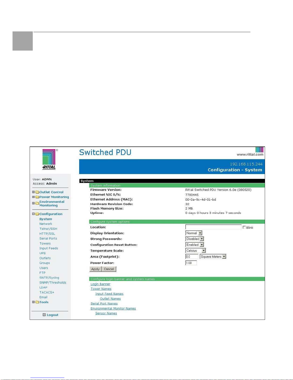
7.2.4 Configuration
The Configuration section offers access to all unit
configuration options. This section is available to
administrative level users only.
System
The System configuration page is used for reference of system information such as Ethernet NIC
Serial Number, Ethernet MAC address and system
firmware and hardware revisions as well as assignment and maintenance of other system wide
configurations.
For descriptive names, up to 24 alphanumeric
and other typeable characters (ASCII 33 to 126
decimal) are allowed; spaces are not allowed.
Creating a pre-login banner:
Click on the Login Banner link.
On the subsequent Login Banner page, enter a
pre-login banner and press Apply.
Note!
The pre-login banner may be up to
2070 characters in length and is displayed prior to the login prompt. If left
blank, no system banner will be displayed prior to login prompt.
Creating a descriptive system location name:
Enter a descriptive name and press Apply.
Configuring the Input Current LED display
orientation:
Select Normal or Inverted from the drop-down
menu and press Apply.
Enabling or disabling strong password requirements:
The PDU supports enforcement of strong passwords for enhanced security. When enabled, all
new passwords must be a minimum of 8 characters in length with at least one uppercase letter,
one lowercase letter, one number and one special
character.
Acceptable strong passwords:
n0tOnmyw@tch
john2STI?
H3reUgo!
Note!
Strong password requirements also
enforce a minimum change of four character positions when defining new
strong passwords.
Select Enabled or Disabled from the Strong
Passwords drop-down menu and press Apply.
Note!
The strong password requirement is
applied against all new passwords.
Enabling or disabling the external reset button:
Select Enabled or Disabled from the Configuration Reset Button drop-down menu and press
Apply.
Setting the temperature scale:
Select Celsius or Fahrenheit from the Temperature Scale drop-down menu and press Apply.
Setting the system area:
The Total Area value is used to provide calculated
power usage over the total area of the system
displayed in the Power Monitoring pages.
In the Total Area field, enter the area in square
feet for the system and press Apply.
Setting the system input power factor:
The Power Factor value is used to provide calculated power usage displayed in the Power Monitoring pages.

Operations 7
Switched Power Distribution Unit
15
EN
Setting the system 3-phase load out-of-bound
threshold:
This setting to use for devices with 3-phase input
voltages to notify of a system imbalance between
the three phases of power.
In the 3-Phase Load Out-of-Bounds Threshold
field, enter a value from 0 to 100% and press Ap-
ply.
Creating a descriptive unit name:
Click on the Tower Names link.
On the subsequent Tower Names page, enter a
descriptive name and press Apply.
Creating a descriptive input feed name:
Click on the Input Feed Names link.
On the subsequent Input Feed Names page, en-
ter a descriptive name and press Apply.
Creating a descriptive outlet name:
Click on the Outlet Names link, which will open
the Outlets configuration page. You can change
the names by clicking on the “Edit” button.
Creating a descriptive serial port name:
Click on the Serial Port Names link, which will
open the Serial Ports configuration page. See
Serial Ports on page 17 for additional information
on creating descriptive serial port names.
You can change the names by clicking on the
“Edit” button.
Creating a descriptive Environmental Monitor
name:
Click on the Environmental Monitor Names link.
On the subsequent Environmental Monitor Names
page, enter a descriptive name and press Apply.
Creating descriptive sensor names:
Click on the Sensor Names link.
On the subsequent Sensor Names page, enter a
descriptive name and press Apply.
Network
The Network configuration page is used for maintenance of the network interface. From this page
an administrator may configure the IP address,
subnet mask, gateway address, DNS addresses
as well as view the link status, speed and duplex
value.
The PDU is configured with the following network
defaults to allow unit configuration out-of-the-box
through either Telnet or HTML:
• IP address: 192.168.1.254
• Subnet Mask: 255.255.255.0
• Gateway: 192.168.1.1
Note!
Contact your system administrator for
instructions in reconfiguring the network
connection. Reconfiguration of your
network connection may require a restart to take effect.
The initial local PC network connection must be
configured as noted below:
• IP address: 192.168.1.x (where x is 2-253)
• Subnet Mask: 255.255.255.0
Note!
The unit must be restarted after network
configuration changes.
Enabling or disabling DHCP support:
Select Enabled or Disabled from the DHCP dropdown menu and press Apply.
Setting the IP address, subnet mask, gateway
or DNS address:
In the appropriate field, enter the IP address, subnet mask, gateway address or DNS address and
press Apply.
Telnet/SSH
The Telnet/SSH configuration page enables or
disables Telnet and SSH support and configures
the port number that the Telnet or SSH server
watches. For more information on SSH see page
49 in 8Advanced Operations.

Operations 7
16
Switched Power Distribution Unit
EN
Enabling or disabling Telnet or SSH support:
Select Enabled or Disabled from the appropriate
Server drop-down menu and press Apply.
Changing the Telnet or SSH server port number:
In the appropriate Port field, enter the port number and press Apply.
Enabling or disabling SSH server authentication methods:
The PDU SSH server supports two authentication
methods for security and validation: Password and
Keyboard-Interactive.
Password is an authentication method where the
SSH client gathers username/password credentials and makes the authentication request to the
SSH sever with the credentials. The Password
method is controlled by the SSH client.
Keyboard-Interactive is an authentication method
where the SSH server controls an information field
followed by one or more prompts requesting credential information from the SSH client. The client
gathers credential information keyed-in by the user
and sends it back to the server. The KeyboardInteractive method is controlled by the SSH
server.
Individual enabling and disabling of the Password
and Keyboard-Interactive authentication methods
are supported to allow an SSH client to be forced
to use a specific method. Although both methods
are available, by enabling the KeyboardInteractive method and disabling the Password
method, the SSH client is forced to used Keyboard-Interactive, which is required to display the
login banner.
Note!
At least one authentication method must
be enabled.
Select the Password checkbox and/or the Key-
board-Interactive checkbox and press Apply.
HTTP/SSL
The HTTP/SSL configuration page used to enable
or disable HTTP and SSL support, configure the
port number that the HTTP server watches and
responds to, selection of the method of authentication used and SSL access level.
Enabling or disabling HTTP or SSL support:
Select Enabled or Disabled from the appropriate
Server drop-down menu and press Apply.
Changing the HTTP server port number:
In the HTTP Port field, enter the port number and
press Apply.
Setting the HTTP authentication method:
The PDU HTTP server supports two authentication methods for security and validation of the
username-password: Basic and MD5 digest.
The Basic method uses Base64 encoding to encode and deliver the username-password over
the network to the HTTP server for decoding and
authentication. This basic method is supported
by all web browsers and offers a minimum level of
security.
Note!
The Base64 algorithm is widely known
and susceptible to packet-sniffer attack
for acquisition of the encoded username-password string.
The MD5 digest method provides stronger protection utilizing one-way encoded hash numbers,
never placing the username-password on the
network. Instead, the sending browser creates a
challenge code based on the hash algorithm,
provided username-password and unique items
such as the device IP address and timestamp,
which is compared against the HTTP server internal user database of valid challenge codes. The
MD5 digest method offers a higher level of security than the Basic method but at present is not
supported by all browsers.
Note!
MD5 is known to be fully supported by
Internet Explorer 5.0+
Select Basic or MD5 from the Authentication
drop-down menu and press Apply.
Setting SSL access level:
PDU SSL supports configuration of SSL connections as being either optional or required. The
default access level is set to optional.

Operations 7
Switched Power Distribution Unit
17
EN
• Optional –Both non-secure (HTTP) and SSL
encrypted connections (HTTPS) are allowed
access.
• Required – ONLY SSL encrypted connections
(HTTPS) are allowed access.
Select Optional or Required from the Secure
Access drop-down menu and press Apply.
Serial Ports
The Serial Ports configuration page is used for
maintenance of the serial port.
Note!
Pass-Thru connections may only be
initiated from the command line interface
via a Telnet/SSH session.
Setting the data-rate for all serial ports:
Select the serial port data-rate from the dropdown menu and press Apply.
Setting the serial port timeout value:
Enter the timeout value (in minutes) in the Connection Timeout field and press Apply.
Creating a descriptive serial port name:
Click on the Edit link in the Action column next to
the port to be configured.
On the subsequent Serial Port Edit page, enter a
descriptive name up to 24 alphanumeric and other
typeable characters - (ASCII 33 to 126 decimal)
are allowed; spaces are not allowed. Press Apply.
Enabling or disabling serial port active signal
checking:
Click on the Edit link in the Action column next to
the port to be configured.
On the subsequent Serial Port Edit page, select
On or Off from the DSR Check drop-down menu
and press Apply.
Towers
The Towers configuration page is used for assignment and/or editing of:
• Descriptive names
• Serial and Model numbers
• Operation voltage types
Note!
If set at the factory, the serial number,
model number and voltage type WILL
NOT be user-editable.
Creating a descriptive tower name:
In the Tower Name field, enter a descriptive name
and press Apply.
Setting the tower serial number:
In the Serial Number field, enter the serial number
of the unit and press Apply.
Setting the tower model number:
In the Model Number field, enter the model number of the unit and press Apply.
Setting the operational AC or DC voltage type:
From the AC/DC drop-down menu, select AC or
DC, and press Apply.
Setting the operational AC voltage type:
From the 3-Phase drop-down menu, select yes or
no, and press Apply.
Input Feeds
The Input Feeds configuration page is used for
assignment and/or editing of input feed descriptive names, operational voltage and maximum
load capacity.
Creating a descriptive input feed name:
In the Input Feed Name field, enter a descriptive
name and press Apply.
Setting the infeed operational voltage:
In the Input Feed Voltage field, enter a value from
0 to 480 and press Apply.
Setting the infeed maximum load capacity:
In the Input Feed Load Capacity field, enter a
value from 1 to 255 and press Apply.
UPS
The UPS Configuration page is used for adding a
new UPS device and configuring the UPS devices
connected to PDUs.

Operations 7
18
Switched Power Distribution Unit
EN
To add a new UPS:
Select the UPS manufacturer type from the Type
drop-down list, type an IP address (or hostname)
for the UPS, and press Apply.
To edit the UPS type:
Under the Action heading, click the Edit link for
the UPS to be configured. The Configuration UPS
page reformats to an edit page where UPS device
settings are configured and UPS devices are
associated with an infeed.
Selecting the UPS type:
Select the UPS manufacturer type from the UPS
Type drop-down list and press Apply.
Editing the UPS Hostname/IP Address:
In the Hostname/IP field, type an IP Address or
Hostname and press Apply.
Editing the UPS SNMP GET community string:
In the SNMP GET Community String field, type
the community string configured on the UPS device and press Apply.
Enabling/Disabling UPS voltage polling:
From the “UPS Voltage Polling” drop-down list,
select Enabled or Disabled and press Apply.
Editing the UPS SNMP port number:
In the SNMP-Port field, type the port number and
press Apply.
Associate the UPS with an infeed:
Select the infeed(s) powered by the UPS and
press Apply.
To remove a UPS:
On the Configuration UPS page, under the Action
heading, click the Remove link for the UPS you
want to remove.
Outlets
The Outlets configuration page is used for assignment and/or editing of outlet sequence and
reboot timers, descriptive names and wakeup
states.
Setting the outlet sequencing interval:
Enter the sequencing interval (in seconds) in the
Sequence Interval field and press Apply.
Setting the outlet reboot delay:
Enter the reboot interval (in seconds) in the Reboot Delay field and press Apply.
Editing the outlet descriptive name:
Click on the Edit link in the Action column next to
the outlet to be configured.
On the subsequent Outlet Edit page, enter a descriptive name. Up to 24 alphanumeric and other
typeable characters (ASCII 33 to 126 decimal) are
allowed; spaces are not allowed. Press Apply.
Changing the outlet wakeup state:
Click on the Edit link in the Action column next to
the outlet to be configured.
On the subsequent Outlet Edit page, select On,
Off or Last from the Wakeup State drop-down
menu and press Apply.
Setting the outlet Post-On delay:
Click on the Edit link in the Action column next to
the outlet to be configured.
On the subsequent Outlet Edit page, enter the
outlet Post-On delay (in seconds) in the Post-On
Delay field and press Apply.
Groups
The Groups configuration page is used for creation and deletion of group and assignment of outlets to groups.
Creating a group:
Enter a descriptive group name in the Group
Name field. Up to 24 alphanumeric and other
typeable characters (ASCII 33 to 126 decimal) are
allowed; spaces are not allowed. Press Apply.
Removing a group:
Click on the Remove link in the Action column for
the group to be removed and press Yes on the
subsequent confirmation window.

Operations 7
Switched Power Distribution Unit
19
EN
Adding and Deleting outlets from a group:
Press the Edit link in the Action column for the
associated group.
On the subsequent Group Edit page, select or
deselect outlets to be included in that group.
Press Apply.
Users
The Users configuration page is used for creation
and removal of usernames, assignment of accessible outlets and group, assignment of privilege
levels and the changing of user passwords.
Creating a new user:
Enter a user name in the Username field. Up to
16 alphanumeric and other typeable characters
(ASCII 33 to 126 decimal) are allowed; spaces
are not allowed.
Enter a password for the new user and verify in
the Password and Verify Password fields. For
security, password characters are not displayed.
Press Apply.
Removing a user:
Click on the Remove link in the Action column for
the user to be removed and press Yes on the
subsequent confirmation window.
Changing a user password:
Click on the Edit link in the Action column for the
associated user.
On the subsequent User Edit page, enter a password and verify the new password for the new
user in the Password and Verify Password fields.
For security, password characters are not displayed. Press Apply.
Changing a user’s access privilege level:
The PDU has the following defined privilege levels:
• Admin: Full-access for all configuration, control
(On, Off, Reboot), status and
serial/Pass-Thru ports.
• Power User: Full-access for all control (On,
Off, Reboot), status and
serial/Pass-Thru ports.
• User: Partial-access for control (On, Off, Reboot), status and Pass-Thru of assigned outlets, groups and serial/Pass-Thru ports.
• Reboot-Only: Partial-access for control (Reboot), status and Pass-Thru of assigned
out-
lets, groups and serial/Pass-Thru ports.
• On-Only: Partial-access for control (On), status
and Pass-Thru of assigned
outlets, groups and
serial/Pass-Thru ports.
• View-Only: Partial-access for status and
Pass-Thru of assigned outlets, groups and serial/Pass-Thru ports.
The administrator may also grant administrative
privileges to other user accounts allowing the PDU
to have more than one administrative-level user.
Note!
You cannot remove administrative privileges from the Admn user unless another user has already been given administrative access level privileges created.
Click on the Edit link in the Action column for the
associated user.
On the subsequent User Edit page, select Admin,
Power-User, User, Reboot-only, On-only
or View-only from the Access Level drop-down
menu and press Apply.
Granting or removing Environmental Monitoring viewing privileges:
Click on the Edit link in the Action column for the
associated user.
On the subsequent User Edit page, select Yes or
No from the Environmental Monitoring drop-down
menu and press Apply.
Adding and Deleting outlet access:
Click on the Outlets link in the Access column for
the associated user.
On the subsequent User Outlets page, select or
deselect outlets to be accessed by the user and
press Apply.
Adding and Deleting group access:
Click on the Groups link in the Access column for
the associated user.
On the subsequent User Groups page, select or
deselect group to be accessed by the user and
press Apply.
Adding and Deleting serial port access:
Click on the Ports link in the Access column for
the associated user.
On the subsequent User Ports page, select or
deselect ports to be accessed by the user and
press Apply.

Operations 7
20
Switched Power Distribution Unit
EN
FTP
The FTP configuration page is used for setup and
maintenance of all settings required to perform an
FTP firmware upload, configure automatic FTP
updates or system configuration uploads/downloads.
Setting the FTP Host Address:
Enter the IP address or hostname in the Host field
and press Apply.
Setting the FTP username:
Enter the FTP server username in the Username
field, and press Apply.
Setting the FTP password:
Enter the FTP server password in the Password
field, and press Apply.
Setting the file path:
Enter the path of the file to be uploaded in the
Directory field, and press Apply.
Setting the filename for upload:
Enter the filename of the file to be uploaded in the
Filename field, and press Apply.
Testing the FTP upload configuration:
This test validates that the unit is able to contact
and log onto the specified FTP server, download
the firmware file and verify that the firmware file is
valid for this unit.
Press Test.
Enabling or disabling automatic updates:
The PDU features the ability to schedule automatic firmware updates. When enabled and configured, the PDU will regularly check the FTP
server for a new firmware image and upload it.
Select Enabled or Disabled from the drop-down
menu and press Apply.
Setting the automatic update scheduled day:
Select the desired day for the automatic updates
from the drop-down menu and press Apply.
Setting the automatic update scheduled hour:
Select the desired hour for the automatic updates
from the drop-down menu and press Apply.
Enabling or disabling the FTP server:
The PDU features the ability to upload and
download system configuration files to ease implementation across multiple PDU devices.
Select Enabled or Disabled from the drop-down
menu and press Apply.
Note!
The FTP server must be enabled for
configuration upload or download.
SNTP/Syslog
The SNTP/Syslog configuration page is used for
setup and maintenance of SNTP and Syslog support.
Setting the SNTP server address:
Enter the IP address or hostname in the Primary
and/or Secondary Host field and press Apply.
Setting the Local GMT offset:
Select the local offset from GMT value from the
drop-down menu and press Apply.
Setting the Syslog server address:
Enter the IP address or hostname in the Primary
and/or Secondary Host field and press Apply.
Changing the Syslog server port number:
In the Syslog Port field, enter the port number and
press Apply.
SNMP/Thresholds
The SNMP/Thresholds configuration page is used
for setup and maintenance of all settings required
to enable SNMP support, and to provide access
to the trap configuration pages.
Note!
Traps are generated according to a
hierarchical architecture; i.e. if a Tower
Status enters a trap condition, only the
Tower Status trap is generated. Infeed
and Outlet Status traps are suppressed
until the Tower Status returns to Normal.

Operations 7
Switched Power Distribution Unit
21
EN
Enabling or disabling SNMP support:
Select Enabled or Disabled from the drop-down
menu and press Apply.
Setting the community strings:
Enter the community string in the appropriate field
and press Apply.
Community strings may be 1 to 24 characters
Setting the trap timer:
Enter a trap timer value in the Error Trap Repeat
Time field and press Apply.
The Error Trap Repeat Time value may be 1 to
65535 (in seconds).
Setting trap destinations:
Enter an IP address or hostname in the appropriate Trap Destination field and press Apply.
Setting IP Restrictions:
Select No Restrictions or Trap Destinations
Only from the IP Restrictions drop-down menu
and press Apply.
Note!
When Trap Destinations Only is selected, SNMP Manager GET and SET
requests are only allowed from the IP
addresses of the defined traps destinations.
Setting the SNMP SysName, SysLocation or
SysContact objects:
In the appropriate field, enter the SysName, SysLocation or SysContact objects and press Apply.
Enabling or disabling tower traps:
Click on the Tower Traps link.
On the subsequent Tower Traps page, select or
deselect the desired traps and press Apply.
Configuring input feed traps and thresholds:
Click on the Input Feed Traps and Thresholds
link.
On the subsequent Input Feed Traps page, select
or deselect the desired traps and press Apply.
For Load traps, enter a maximum load value for
the infeed in the High Load Threshold field and
press Apply.
The default input feed high load threshold is 80%
of the input feed maximum load capacity.
Configuring outlet traps:
Click on the Outlet Traps link.
On the subsequent Outlet Traps and Thresholds
page, select or deselect the desired traps and
press Apply.
Enabling or disabling Environmental Monitor
traps:
Click on the Environmental Monitor Traps link.
On the subsequent page, select or deselect the
desired traps and press Apply.
LDAP
The LDAP configuration page is used for setup
and maintenance of all settings required enabling
LDAP support. For additional information and
configuration requirements.
Enabling or disabling LDAP support:
Select Enabled or Disabled from the LDAP dropdown menu and press Apply.
Changing the LDAP server port:
Enter the port number in the LDAP Port field and
press Apply.
Setting the LDAP server address:
Enter the IP address or hostname in the Primary
and/or Secondary Host field and press Apply.
Enabling or disabling LDAP over TLS/SSL:
Select Yes or No from the Use TLS/SSL dropdown menu and press Apply.
Note!
If LDAP over TLS/SSL is enabled, MD5
binding is disabled.
Setting the LDAP bind password type:
Select Simple or MD5 from the Bind Type dropdown menu and press Apply.
Setting the search bind Distinguished Name
(DN):
Enter the fully qualified distinguished name
(FQDN) in the Search Bind field and press Apply.

Operations 7
22
Switched Power Distribution Unit
EN
Setting the search bind password for Distinguished Name (DN):
Enter the Search Bind Password in the Search
Bind Password field and press Apply.
Setting the user search base Distinguished
Name (DN):
Enter the User Search Base DN in the User
Search Base DN field and press Apply.
Setting the user search filter:
Enter the User Search Filter in the User Search
Filter field and press Apply.
Setting the group membership attribute:
Enter the group membership attribute in the
Group Membership Attribute Field and press Ap-
ply.
Setting the group membership value type:
Select the appropriate value from the drop-down
menu and press Apply.
Configuring the authentication order:
Select Remote -> Local or Remote Only from
the drop-down menu and press Apply.
Note!
Rittal recommends NOT setting the authentication order to Remote Only until
the LDAP has been fully configured and
tested.
Configuring LDAP groups:
Click on the LDAP Groups link at the bottom of
the page.
Creating an LDAP group:
Enter a descriptive group name in the LDAP
Group Name field. Up to 24 alphanumeric and
other typeable characters (ASCII 33 to 126 decimal) are allowed; spaces are not allowed. Press
Apply.
Removing an LDAP group:
Click on the Remove link in the Action column for
the group to be removed and press OK on the
subsequent confirmation window.
Changing an LDAP group’s access privilege level:
Click on the Edit link in the Action column for the
associated LDAP Group.
On the subsequent LDAP Group - Edit page,
select Admin, User, On-only, Reboot-only,
Power-user or View-only from the Access Level
drop-down menu and press Apply.
Granting or removing Environmental Monitoring
viewing privileges:
Click on the Edit link in the Action column for the
associated LDAP Group.
On the subsequent LDAP Group - Edit page,
select Yes or No from the Environmental Monitoring drop-down menu and press Apply.
Adding and Deleting outlet access:
Click on the Outlets link in the Access column for
the associated LDAP Group.
On the subsequent LDAP Group - Outlets page,
select or deselect outlets to be accessed by the
LDAP Group and press Apply.
Adding and Deleting outlet group access:
Click on the Groups link in the Access column for
the associated LDAP Group.
On the subsequent LDAP Group - Groups page,
select or deselect outlet groups to be accessed by
the LDAP Group and press Apply.
Adding and Deleting serial port access:
Click on the Ports link in the Access column for
the associated LDAP Group.
On the subsequent LDAP Group - Ports page,
select or deselect ports to be accessed by the
LDAP Group and press Apply.
TACACS+
The TACACS+ configuration page is used for
setup and maintenance of all settings required to
enable TACACS+ support.
Enabling or disabling TACACS+ support:
Select Enabled or Disabled from the TACACS+
drop-down menu and press Apply.
Changing the TACACS+ server port:
Enter the port number in the Port field and press
Apply.

Operations 7
Switched Power Distribution Unit
23
EN
Setting the TACACS+ server address:
Enter the IP address or hostname in the Primary
and/or Secondary Host field and press Apply.
Configuring the authentication order:
Select Remote -> Local or Remote Only from
the drop-down menu and press Apply.
Setting the TACACS+ encryption key:
Enter a key and verify the new key the Encryption
Key and Verify New Encryption Key fields. Press
Apply.
For security, key characters are not displayed.
Configuring TACACS+ privilege levels:
Click on the TACACS+ Privilege Levels link at
the bottom of the page.
Changing an TACACS+ Privilege Level’s access
privilege level:
Click on the Edit link in the Action column for the
associated TACACS+ Privilege Level.
On the subsequent TACACS+ Privilege Level Edit page, select Admin, User, On-only, Re-
boot-only, Power-user or View-only from the
Access Level drop-down menu and press Apply.
Granting or removing Environmental Monitoring
viewing privileges:
Click on the Edit link in the Action column for the
associated TACACS+ privilege level.
On the subsequent TACACS+ Privilege Level Edit page, select Yes or No from the Environmental Monitoring drop-down menu and press
Apply.
Adding and Deleting outlet access:
Click on the Outlets link in the Access column for
the associated TACACS+ Privilege Level.
On the subsequent LDAP Group - Outlets page,
select or deselect outlets to be accessed by the
TACACS+ Privilege Level and press Apply.
Adding and Deleting outlet group access:
Click on the Groups link in the Access column for
the associated TACACS+ Privilege Level.
On the subsequent LDAP Group - Groups page,
select or deselect outlet groups to be accessed by
the TACACS+ Privilege Level and press Apply.
Adding and Deleting serial port access:
Click on the Ports link in the Access column for
the associated TACACS+ Privilege Level.
On the subsequent LDAP Group - Ports page,
select or deselect ports to be accessed by the
TACACS+ Privilege Level and press Apply.
E-Mail
The Email configuration page is used for setup
and maintenance Email log support.
Enabling or disabling Email support:
Select Enabled or Disabled from the Email Notifications drop-down menu and press Apply.
Setting the SMTP server address:
Enter the IP address or hostname in the SMTP
Host field and press Apply.
Changing the SMTP server port:
Enter the port number in the SMTP Port field and
press Apply.
Setting the ‘From’ email address:
Enter the ‘from’ email address in the ‘From’ Address field and press Apply.
Setting the ‘To’ email address:
Enter the ‘to’ email address in the Primary or
Secondary ‘Send To’ Address field and press
Apply.
Enabling or disabling event type notifications:
Select Enabled or Disabled from the Include…Messages drop-down menus and press
Apply.
Features
The Features configuration page is used for activation maintenance of special features purchased
from Rittal. From this page an administrator may
review all activated features as well as activate
newly purchased features.
To activate a special feature:
In the Feature Key Value field, enter the activation key provided by Rittal and press Apply.
Operations 7
24
Switched Power Distribution Unit
EN
Note!
A restart of the PDU is required after
activating new special features.
7.2.5 Tools
The Tools section contains access to rebooting
the unit, uploading new firmware as well as resetting the unit to factory defaults. This section is
available to administrative level users only.
Ping
The Ping feature may be used to test the PDU`s
ability to contact another Ethernet enabled device’s IP address. For LDAP support, it may also
be used to test the configuration of the Domain
Name server IP address by testing for proper
name resolution.
Change Password
The Change Password feature allows users to
change their own password.
Note!
An administrator can always assign a
new password.
Changing a password:
Enter the current password, enter a new password and verify the new password. Press Apply.
View Log
The View Log feature enables viewing of the internal system log. This feature logs all authentication attempts, power actions, configuration
changes and other system events. The system
memory stores more than 4000 entries in a continuously aging log. For permanent off-system
log storage, the Syslog protocol is supported.
Note!
The system log is viewable only by users with administrative privileges.
Reviewing the system log:
Click on the First Page, Last Page, Previous
Page or Next page link to navigate through the
log.
Restart
Performing a warm boot:
Select the Restart from the Action drop-down
menu and press Apply.
Note!
System user/outlet/group configuration
or outlet states are NOT changed or
reset with this command.
Generating a new SSL X.509 certificate:
Select the Restart and generate a new X.509
certificate from the Action drop-down menu
and press Apply.
Computing new SSH security keys:
Select the Restart and compute new SSH keys
from the Action drop-down menu and press Ap-
ply.
7.3 Command Line Interface
Logging In
Logging in through Telnet requires directing the
Telnet client to the configured IP address of the
unit.
Logging in through the Console (RS232) port
requires the use of a terminal or terminal emulation software configured to support ANSI or
VT100 and a supported data rate (300, 1200,
2400, 4800, 9600, 19200, 38400, 57600, or
115200 BPS) - 8 data bits-no parity-one stop bit
and Device Ready output signal (DTR or DSR).
The default data rate is 9600.
To log in by RS-232 or Telnet:
1. Press Enter. The following appears, where
x.xx is the firmware version:
Rittal Switched PDU - Version x.xx
Username:
2. At the Username: and Password: prompts,
enter a valid username and password. And
press Enter.
Note!
Logging in by Telnet will automatically
open a session. It is not necessary to
press Enter.
 Loading...