

Page 1
Technical System Catalogue
Modular PDU (PSM)
Page 2
Modular PDU (PSM)
Benefits of PSM busbars at a glance
◾ Modular configuration, flexibly extendible
◾ Redundant designs in busbars are supported
◾ Vertical mounting in the rack without loss
of U space
◾ Configuration changes are supported at any
time with the system operational by replacing
the module
◾ Shock-hazard-protected assembly of the
power distribution
◾ Choose from different connection types and
phase currents
◾ Extensive range of accessories for connection
cables and mounting kits
◾ Integral energy measurement and remote
monitoring via CMC III (with special PSM
measuring bars)
Technical System Catalogue/IT infrastructure2
Page 3
Modular PDU (PSM)
Modular PDU (PSM busbars)
The PSM system is a unique, modular power distributor for
integration into IT network and server racks. The configuration
(type and quantity of output slots) can be modified to accommodate altered requirements at any time, even whilst operational.
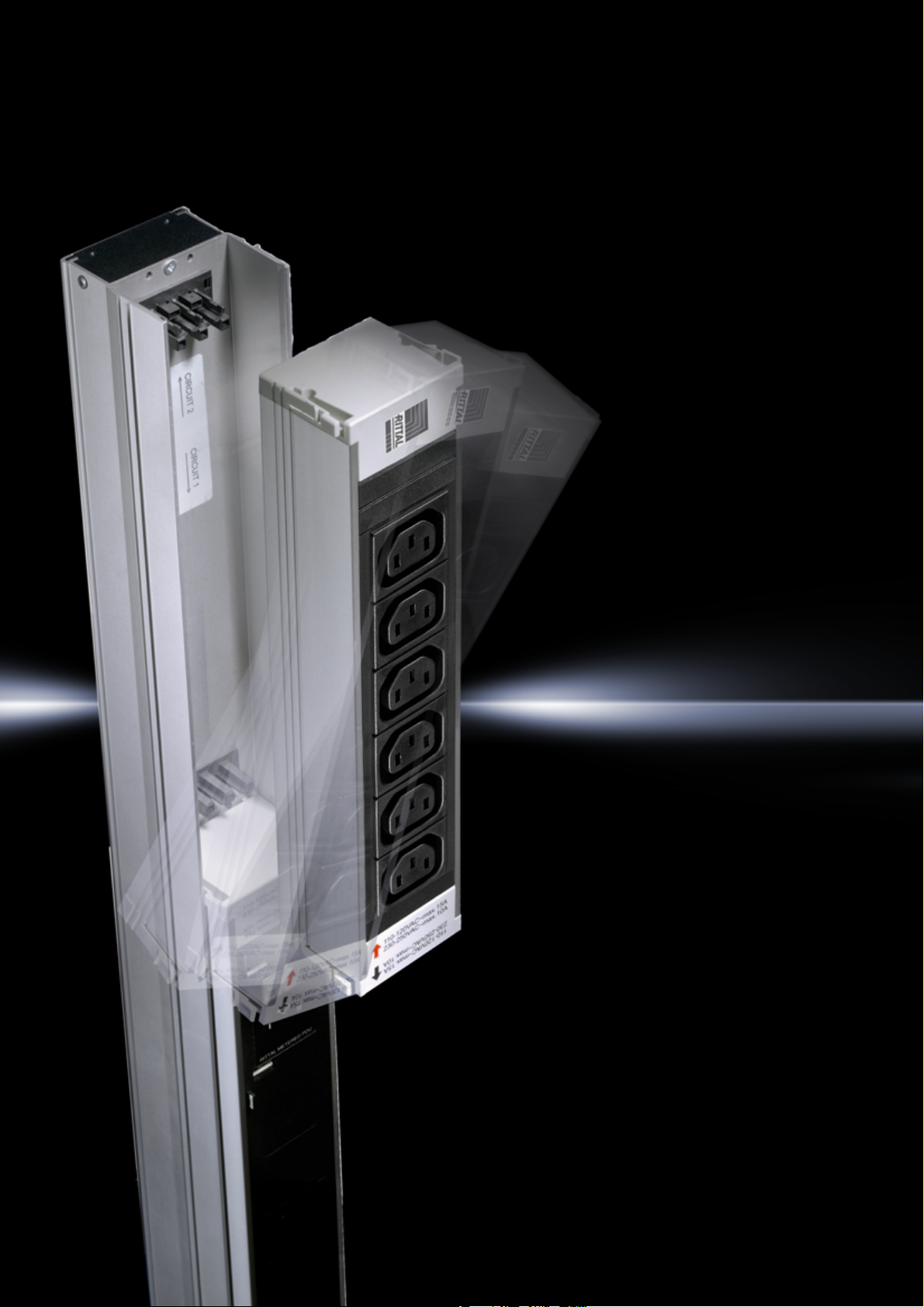
The modular PDU comprises a support rail which is fitted
vertically into the IT rack. This PSM busbar has individual
module slots into which various PSM plug-in modules may
be integrated.
These plug-in modules are available in a range of output pin
patterns and functions. Alongside purely passive distribution
modules, special active modules with switching and measuring
functions may also be integrated into the PSM busbar.
The electrical connection is made using the preassembled
plug&play connection cable available as an accessory, but also
can be made directly by a qualified electrician using the Wago
X-COM connector included in the supply pack.
Some versions of PSM busbars, including all 32 A versions,
have a fixed, prefitted connection cable with CEE connector
(to IEC/EN 60 309).
A range of mounting kits are available for flexible rack mounting,
so as to accommodate varying requirements such as vertically
hinged installation or quick installation in the TS IT rack.
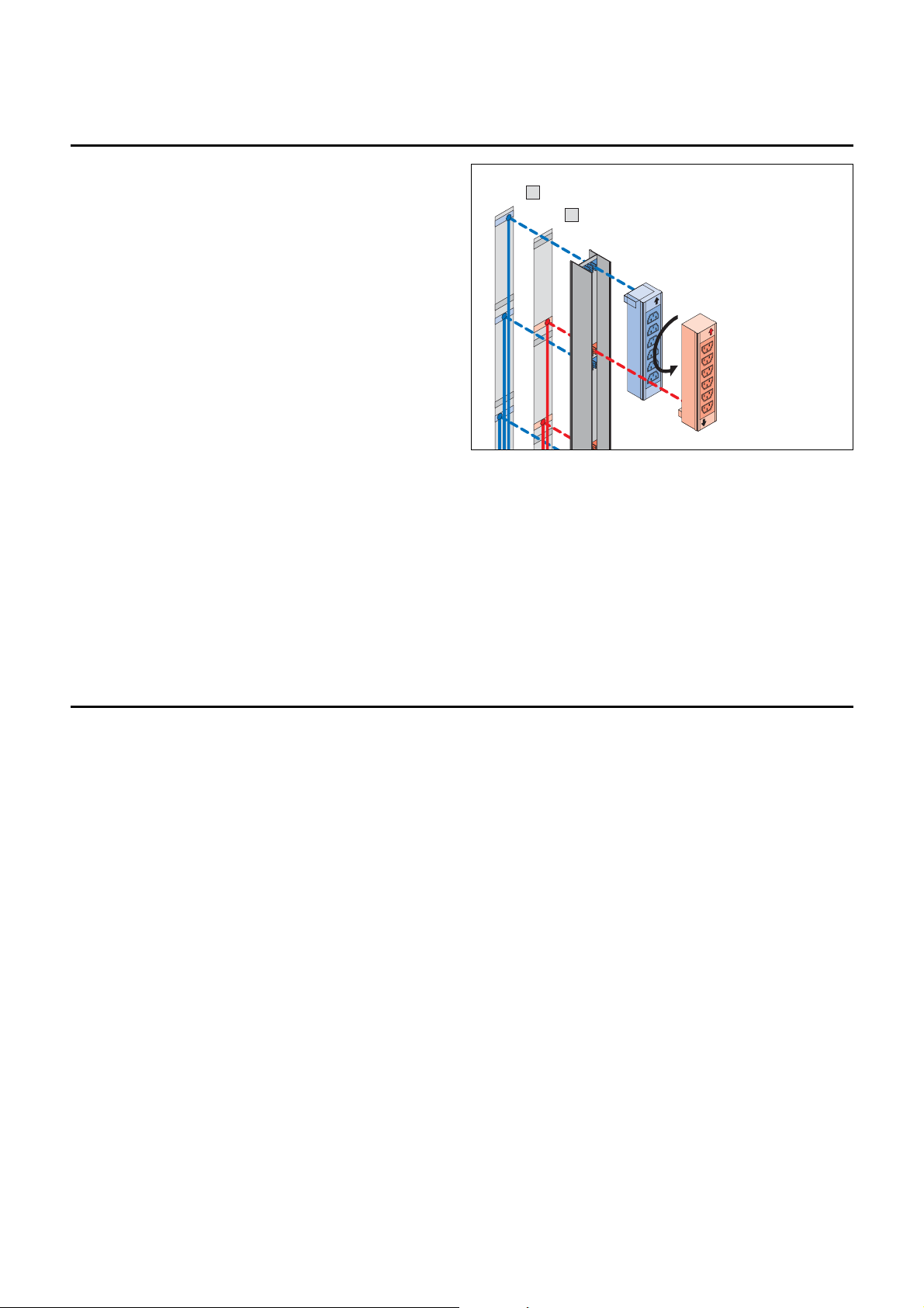
A
B
Each plug-in module
picks off a phase on the
support rail, either from
infeed A or from the
redundant infeed B,
depending on the
direction of connection.
Criteria for selecting the correct PSM busbar
◾ Enclosure height
◾ No. of infeeds
◾ Type of infeed (e.g. fixed infeed)
◾ Phase current (16 A, 32 A)
◾ No. of phases (single or three-phase)
◾ No. of required PSM plug-in modules
◾ Additional measurement and management functions required
3Technical System Catalogue/IT infrastructure
Page 4

Modular PDU (PSM)
Function
Model No. 7856.005 7856.006 7856.008 7856.010 7856.020 7856.321 7856.323 7856.050 7856.053
Minimum height of rack (mm) 2000 2000 2200 1200 2000 2000 2000 2000 2000
Type of connection/length Fixed/3 m Fixed/3 m WAGO jack WAGO jack WAGO jack Fixed/3 m Fixed/3 m WAGO jack Fixed/3 m
Connector CEE CEE Various Various Various CEE CEE Various CEE
No. of infeeds 122221121
No. of phases 333331331
Phase current (A) 16 16 16 16 16 32 32 16 32
Various connection cables, also for single-phase
connection
––
◾◾◾––◾ –
No. of PSM module slots 778476666
Integral energy measurement of voltage, current,
active power, apparent power, active energy, power
factor, mains frequency
–––––––
◾◾
Measurement accuracy (U, l, f, P, S) –––––––2%2%
Measurement accuracy (E/kWh) –––––––1%1%
Graphic display for visualising the measurements
(24 V DC required)
–––––––
◾◾
CAN bus interface for connecting to CMC III system –––––––◾◾
Web server (IPv4, IPv6, SNMP, SSH) via CMC III
(PU III - 7030.000)
–––––––
◾◾
E-mail forwarding of exceeded limits and alarms
(CMC III required)
–––––––
◾◾
Operating temperature (°C) 5 – 45
Ambient humidity % (non-condensing) 10 – 90
Protection category IP (to IEC 60529) IP 20
Approvals CE CE CE CE/VDE CE/VDE CE CE CE CE
Technical System Catalogue/IT infrastructure4
Page 5

Modular PDU (PSM)
Modular PDU (PSM plug-in modules)
Choose from a wide range of PSM plug-in modules to configure
the PSM busbar with the required output slots. The modules
are snap-fastened into the PSM busbar without the use of
tools, and the slots are then available for the equipment.
It may be assembled while operational and connected to the
power supply (but only off-load). A range of different pin
patterns and functions are available (e.g. switching the outputs
and power measurement), so that every PSM busbar can be
configured individually depending on the preferred application.
Data communication and network connection occur via the
CMC III. Together with the CMC III and in conjunction with other
CMC III sensors e.g. for ambient parameters such as temperature and humidity, this creates a comprehensive monitoring
solution.
PSM plug-in modules (passive, distribution only)
Model No. 7856.080 7856.082 7856.100 7856.240 7856.230 7856.070 7856.220 7856.090 7856.120 7856.191 7859.120 7859.130
Occupied slots in PSM busbar 1
Pin pattern (type)
IEC
60320
C13
IEC
60320
C13
CEE 7/3
type F
CEE 7/3
type F
IEC
60320
C19
IEC
60320
C13
IEC
60320
C13
CEE 7/3
type F
CEE 7/5
type E
T 23
type J
IEC
60320
C13
IEC
60320
C19
Number of outputs 664446444464
Colour of slots black red black red black black black black black black black black
Lockable connectors (optional)
◾◾––––◾ –––––
Miniature fuse per output ––––––
◾ –––––
Thermal overload protection –––––
◾ – ◾ ––––
Optical LED current display
(total current)
––––––––––
◾◾
Switchable outputs
(via CMC III)
––––––––––––
Current measurement per
module/output
––––––––––––
Dimensions W x H x D mm 52 x 250 x 45
Operating temperature (°C) 5 – 45
Ambient humidity %
(non-condensing)
10 – 95
Material Extruded aluminium section/plastic
Approvals CE CE CE/VDE CE CE CE CE CE CE CE CE CE
5Technical System Catalogue/IT infrastructure
Page 6

Modular PDU (PSM)
PSM plug-in modules with power monitoring and output switching function
As well as passive PSM plug-in modules, which merely
distribute power via various types of output slots, there are
also smart PSM plug-in modules with additional functions.
These modules are ideally suited for retrofitting a power and
load management system and provides remote switching
functionality if the PSM busbar has already been installed and
commissioned. There is a choice of three modules with
identical functions but different slot configurations.
Data forwarding (or switching function) occurs with the aid of
a CMC III PU or PU compact. The modules have a CAN bus
interface for direct connection.
One LC display per module is available for local display in the
rack. The colour of the background lighting visualises the
various system states and exceeded limits clearly and
intelligibly. LEDs on the slots visualise the current switching
status.
Functions:
◾ Measurement of power consumption per module
◾ Output slots may be switched individually and in groups
◾ LEDs per slot to visually indicate the switching status
◾ LC display with multi-coloured backlight for local display
◾ Adjustable limits for voltage, current and active power
◾ Configurable overload detection per module
◾ High level of measurement accuracy
◾ Alarm signalling via the display
◾ Alarm management via CMC III (e.g. e-mail or text message)
◾ Visualisation of the switching status on the CMC III website
and RiZone
◾ Up to 16 PSM modules on one CMC III PU (per IP address)
◾ Rights management via CMC III (e.g. restriction of the
switching function)
◾ Facilitates the implementation of requirements
to EN 16001/ISO 50001 and EN 50600-2-2
◾ Stable aluminium section with plastic socket inserts
◾ Supports universal connector locking of the IEC 60320
C13 and C19 slots
◾ Supports the closure of unneeded IEC 60320
C13 and C19 slots
◾ PSM module is easily fitted into and removed from
the PSM busbar, for use at different locations
◾ Compatible with the European PSM busbar range
◾ Depending on the PSM busbar, up to four modules per
bar may be fitted
Technical System Catalogue/IT infrastructure6
Page 7

Modular PDU (PSM)
PSM plug-in modules with power monitoring and switching function
Product characteristics Unit PSM module type
Model No. 1 pc(s). 7859.410 7859.420 7859.430
No. of IEC 60320 C13 slots 822
No. of IEC 60320 C19 slots –4–
No. of earthing-pin slots (CEE 7/3 or type F) ––4
Total no. of all switchable outputs 866
No. of slots required in the PSM busbar 2
Module dimensions (W x H x D) mm 53 x 500 x 45
Section Aluminium, anodised
Plastic PA6 GF 30 V1
Electrics
No. of infeeds per module Qty. 1
Input voltage V AC 230
Input voltage, tolerance V AC 207–250
Rated current A16
Distribution output per module (at 230 V) W 3680
Power supply (via CMC III system, alternatively with power pack 7201.210) V DC 18-24
Functional overview
Measurement functions Per m odu le
Switching functions Per output slot
Relay type Dual coil/bistable
Relay switching load VA 4000
Display (LC matrix display with coloured backlight) Per m odu le
LEDs (blue) to indicate switching status Per output slot
Status LEDs - CAN bus communication 4 pc(s). Per module
Keys for operation & configuration 4 pc(s). Per module
Location sensor for correct display and Web view in 90° increments
Connector lock (optional, for C13 & C19 slots) 20 pc(s). 7955.020
Measurement functions
Voltage (V), current (A), frequency (Hz) ◾
Active power (kW), active energy (kWh) ◾
Reactive power (kVar), reactive energy (kVarh)
◾
Apparent power (kVA),
apparent energy (kVAh)
◾
Power factor (cos ?), crest factor (amplitude factor)
◾
Operating hours meter (d. h. min) ◾
Measurement accuracy %+/–1
Resettable measurement functions/reset via software/interval measurement
Active energy (kWh) ◾
Operating hours meter (h) ◾
Threshold values (warning/alarm), freely configurable
Voltage, current, power
Connectivity / management functions (in conjunction with CMC III)
Maximum no. of modules that may be used per CMC III Processing Unit Qty. 16
Maximum no. of modules that may be used per CMC III Processing Unit Compact Qty. 4
CAN bus for direct linking to CMC III system pc(s). 2 (RJ45)
Network functionality (only in conjunction with CMC III system) IPv4, IPv6, SNMPv3, Modbus/TCP, OPC-UA
Ambient conditions
Operating temperature
°C
+5…+50
Operating temperature (at max. 8 A per output slot)
°C
+5…+60
Storage temperature °C -20…+70
Ambient humidity (non-condensing) rel. humidity, % 10 – 90
Maximum installation height m 2000
Overvoltage category II
Contamination level 2
Protection class (IEC 60529) IP 20
Approvals and standards
Approval CE, RoHS II
Standards (excerpt)
Low Voltage Directive 2014/35/EU
EMC Directive 2014/30/EU
EN 50600-2-2
EN 60 950
7Technical System Catalogue/IT infrastructure
Page 8

Modular PDU (PSM)
+ –
+
–
+ –
+ –
+ –
+ –
Control and monitoring with CMC III management system
The CAN bus connection with the CMC III monitoring system
is made for control and remote management of the PSM busbars, PSM measurement modules and MID measurement
modules (482.6 mm (19") inline meter). The CMC III provides
a connection to the outside world using a range of protocols
(IPv4, IPv6, SNMP, OPC-UA, Modbus/TCP, SSH etc.) In this
way, multiple busbars and PSM modules, even distributed
across several racks, can be combined and managed under
one IP address. Logical links with other CMC III sensors (e.g.
temperature, humidity, smoke alarm etc.) are also supported.
The benefits of PSM plug-in modules at a glance:
◾ May be installed and replaced at any time, even while live,
without specialist knowledge
◾ Various pin patterns for every application
◾ Modules with switching and measurement functions, also
suitable for retrofitting
◾ Versions with miniature fuses and load display via LED are
available
◾ VDE-tested (some versions)
◾ Compact design, despite modularity
PSM measurement modules, connection to CMC III
Max. 8 modules per CAN bus
Connection of PSM measurement modules to the CMC III PU and
network 230 V supply to the PSM modules via PSM busbar!
PSM measurement bars, connection to CMC III
Max. 4 PSM measurement bars per CAN bus
Connection of PSM measurement bars to the CMC III PU and
network
IP network
IP network
+ –
+ –
+ –
+ –
+ –
+
–
Type of cabling:
230 V/400 V mains
24 V DC, buffered
CMC III CAN bus
Network/IP/SNMP
Type of cabling:
230 V/400 V mains
24 V DC, buffered
CMC III CAN bus
Network/IP/SNMP
Technical System Catalogue/IT infrastructure8
Page 9

Modular PDU (PSM)
Visual load management with PSM
In many cases, fast identification of the module or phase load is
useful. However, companies often shy away from investing in
complex measurement technology. For such cases, special
PSM modules are available which visualise the current rating of
all connected equipment without the need for additional accessories. These modules can be integrated into any existing PSM
busbar, or replace existing PSM modules.
There are two versions available with 6 x IEC 60320 C13
(7859.120) or 4 x IEC 60320 C19 (7859.130) output slots.
Using these PSM modules with LED current display allows you
to visualise the load distribution in the PSM busbar. You can
see at a glance which PSM module can accommodate further
equipment without causing a phase overload.
Once the prescribed load limit of the module is reached, any
remaining slots may be sealed with optionally available
IEC 60320 C13 or C19 covers to prevent mistakes being made
in the hectic environment of data centre operation.
The limits are preset in the factory and cannot be altered.
Current limits:
0 – 7 A (green), 7 – 13 A (yellow) and >13 A (red)
These PSM plug-in modules with LED load display are ideally
suited for retrofitting to existing PSM installations to enhance
the reliability of the supply.
To match the LED modules with load display, IEC 60320
C13/C19 slot covers are also available, to prevent overloading
with additional equipment. The cover is easily removed with
a release tool if necessary.
Ingeniously simple: Optical load indicators
Phase loads are clearly visible at all times. No more worries
about unnoticed overloading or unbalanced power distribution
in the rack.
Covers for secure load management
PSM plug-in module with load display
9Technical System Catalogue/IT infrastructure
Page 10

Modular PDU (PSM)
PSM MID measurement module for
482.6 mm (19") installation
This measurement device is connected into the connection
cable (infeed) of the equipment or the power distributor, and
records the consumed active energy with 1% accuracy.
MID approval means that the module is licensed for use in the
European Union for energy billing purposes. As well as
measuring energy, it also measures other performance data
such as voltage, current, active and apparent power, power
factor, and neutral conductor current. Measurement of the
neutral conductor current aids the reliable detection of asymmetries (different phase utilisation levels) in power distribution.
The meter is fitted horizontally in the 482.6 mm (19") level.
There are two versions available, for 16 A and 32 A phased
current, which are connected using cable sets available as
accessories. A special preassembled connection cable set is
available for connecting to PSM busbars with Wago X-COM
connectors. In this way, a power distributor without measurement capabilities is quickly and easily extended.
Approval for energy billing purposes is valid for 8 years and can
be extended for a further 8 years by recalibrating.
IT network/server rack
IT rack with redundant power
supply (PSM or PDU basic )
Measurement via MID inline
meter
Type of cabling:
230 V/400 V mains
24 V DC, buffered
CMC III CAN bus
Network/IP/SNMP
Serial connection
CMC III power pack
(redundant design with
2 power packs optionally
supported)
CMC III PU/PU Compact
IP mains
Circuit A Circuit B
Max.
8 MID modules
What is MID?
MID stands for “Measurement Instruments Directive” and
regulates 10 types of measurement equipment based on
EU Directive 2004/22/EC.
The aim is to harmonise the approval of measurement
equipment in the Member States. However, country-specific
regulations (such as the Calibration Act in Germany) continue
to apply.
MID regulates the entire manufacturing process, from
development, to production, through to final testing of the
measurement equipment. General and device-specific
performance requirements are defined in the MID, which the
manufacturer must comply with. Following successful testing,
the MID-approved devices are labelled and may be sold
throughout the EU.
Benefits of the MID measurement module:
◾ Easy to install active energy meter based on the plug & play
system
◾ Variants for 16 A and 32 A phase current
◾ Two independent circuits in each case (3-phase)
◾ Pre-assembled connection cable with CEE connector /
coupling
◾ Simple, flexible assembly
◾ Billable MID measurement units
◾ CAN bus for connection to CMC III system
◾ Extensive monitoring functions (via CMC III)
◾ High-MTBF and measurement accuracy of 1%
◾ Energy-efficient electric design – minimal inherent power
consumption
◾ High-quality sheet steel enclosure
+ –
+ –
+
–
+ –
+ –
+
–
+ –
+ –
+ –
Technical System Catalogue/IT infrastructure10
Page 11

◾Enclosures
◾ Power Distribution
◾ Climate Control
◾ IT Infrastructure
◾ Software & Services
You can find the contact details of all
Rittal companies throughout the world here.
www.rittal.com/contact
XWW00090EN1603
 Loading...