

Page 1
CMC III Universalsensor
CMC III Universal Sensor
Détecteur universel CMC III
DK 7030.190
Installationsanleitung und Kurz-Bedienungsanleitung
Installation Guide and Short User's Guide
Notice d'installation et d'utilisation succincte
Page 2
Abbildungen /
Figures / Figures
Abbildungen / Figures / Figures
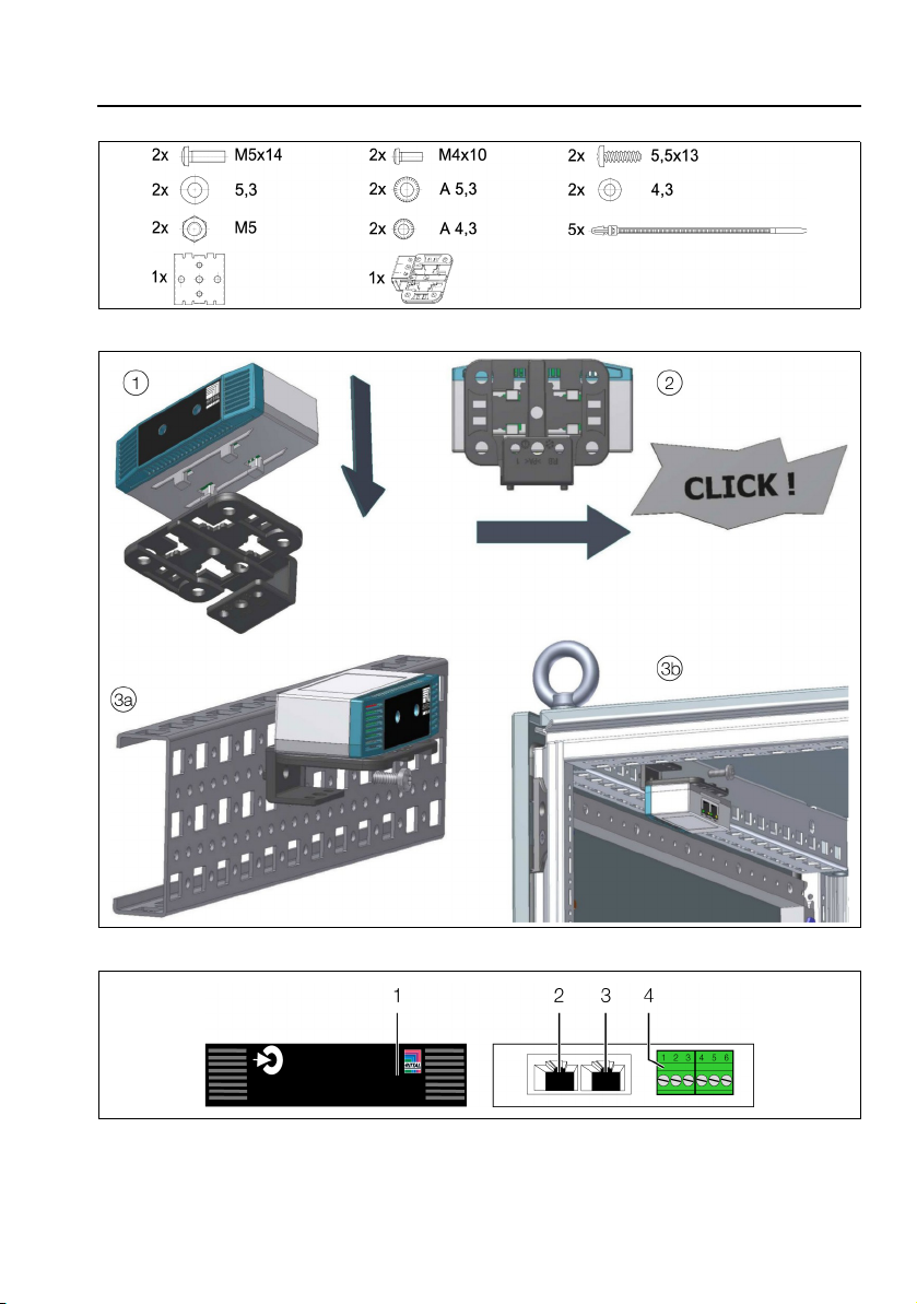
Abb./Fig./Fig. 1: Beigelegtes Zubehör / Provided accessories / Accessoires joints
Abb./Fig./Fig. 2: Montage / Assembly / Montage
Abb./Fig./Fig. 3: Anzeigeelemente, Stecker und Anschlüsse / Display elements, plugs and connectors /
Organes de signalisation, fiches et raccordements
2 Rittal CMC III Universalsensor / Universal Sensor / Détecteur universel
Page 3

DE
Hinweise zur Dokumentation, Sicherheitshinweise, Produktbeschreibung
1 Hinweise zur Dokumentation
Diese Installations- und Kurz-Bedienungsanleitung richtet sich an versiertes Fachpersonal und enthält
nur die wichtigsten Informationen zur Montage, Installation und Funktion des CMC III Univsersalsensors
(nachfolgend Univsersalsensor genannt).
1.1 Mitgeltende Unterlagen
Montage-, Installations- und Bedienungsanleitung CMC III Univsersalsensor.
Sie ist unter www.rittal.de verfügbar und enthält die vollständigen anwendungsrelevanten Informationen
und technischen Daten zum Univsersalsensor in Hinblick auf:
– Weitere Montagemöglichkeiten
– Funktionen
– Konfigurationsmöglichkeiten
– Detaillierte Bedienungsanweisungen
– Fehlerbehebung
2 Sicherheitshinweise
– Montage und Installation des Univsersalsensors dürfen nur durch versiertes Fachpersonal erfolgen.
– Das Gehäuse des Univsersalsensors darf nicht geöffnet werden.
– Der Univsersalsensor darf nicht in Kontakt mit Wasser, aggressiven oder entzündbaren Gasen und
Dämpfen kommen.
– Der Univsersalsensor darf nur innerhalb der spezifizierten Umgebungsbedingungen betrieben werden
(vgl. Abschnitt 3.4).
DE
3 Produktbeschreibung
3.1 Funktionsbeschreibung
Der Univsersalsensor enthält folgende Schnittstellen:
– 2 digitale Eingänge
– analoger Eingang 4-20 mA
–2 S
-Bus-Energiezähler
0
– eine Wiegand-Schnittstelle 56 Bit oder 86 Bit
Die Schnittstellen können über die Website der CMC III PU konfiguriert werden. Der Univsersalsensor
liefert die gemessenen Werte an die angeschlossene CMC III PU. Er enthält eine Kennung, durch die er
automatisch von der CMC III PU erkannt wird.
3.2 Bestimmungsgemäße Verwendung
Der CMC III Univsersalsensor dient ausschließlich zur Datenaufnahme über eine der verfügbaren
Schnittstellen. Er darf nur zusammen mit der CMC III PU verwendet werden. Eine andere Verwendung
ist nicht bestimmungsgemäß.
3.3 Lieferumfang
– CMC III Univsersalsensor
– Beigelegtes Zubehör (Abb. 1)
– Installations- und Kurz-Bedienungsanleitung
Rittal CMC III Universalsensor 3
Page 4
DE
Montage, Installation und Bedienung
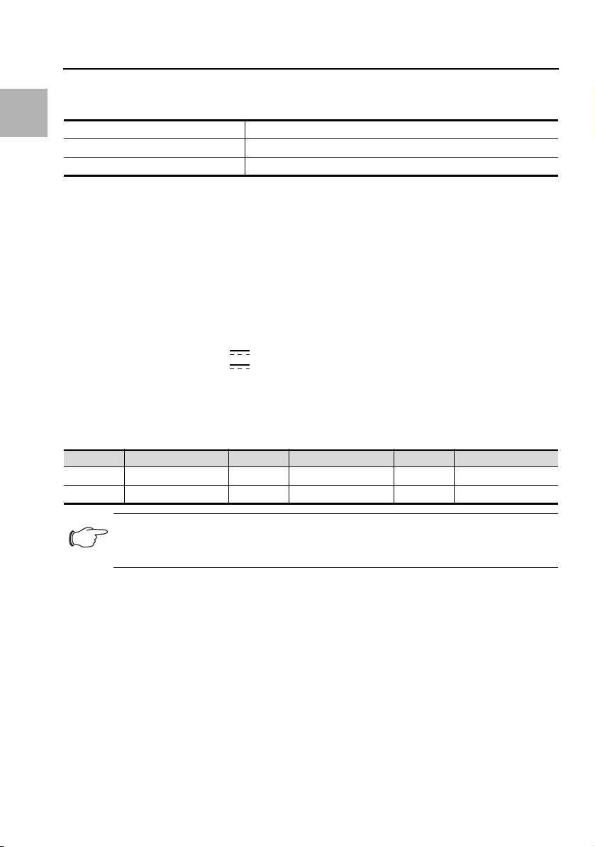
3.4 Betriebsbedingungen
Der Univsersalsensor darf nur unter folgenden Betriebsbedingungen betrieben werden:
Temperatur-Einsatzbereich: +0°C bis +55°C
Feuchtigkeits-Einsatzbereich: 5% bis 95% relative Feuchte, nicht kondensierend
Schutzart: IP 30 nach IEC 60 529
4 Montage
4.1 Montageanweisung
Die Montage des Univsersalsensors erfolgt gemäß Abb. 2.
5 Installation und Bedienung
5.1 Bedien- und Anzeigeelemente
Die Bedien- und Anzeigeelemente sind in Abb. 3 dargestellt.
Legende zu Abb. 3
1 Multi-LED zur Statusanzeige
2 CAN-Bus-Anschluss, 24 V
3 CAN-Bus-Anschluss, 24 V
4 Universal-Schnittstelle
5.2 Installation
Schließen Sie an der Schnittstelle ein externes Gerät an.
Beachten Sie hierbei die Pinbelegung der Universal-Schnittstelle (Abb. 3, Pos. 4):
Pin Signal Pin Signal Pin Signal
Pin 1 +24 V Pin 3 4-20 mA Eingang Pin 5 Digital Input 1
Pin 2 GND Pin 4 4-20 mA GND Pin 6 Digital Input 2
Hinweis:
Sie können auch mehrere Geräte an der Universal-Schnittstelle anschließen, wenn die
Pinbelegung dies zulässt.
Verbinden Sie den Univsersalsensor über ein CAN-Bus-Verbindungskabel mit der CMC III PU bzw.
den benachbarten Elementen im CAN-Bus (Abb. 3, Pos. 3, 4).
Anzeige der Statusänderung:
– Die beiden grünen sowie die beiden roten CAN-Bus LEDs am CAN-Bus-Anschluss blinken.
– Die Multi-LED der Processing Unit blinkt dauerhaft in der Reihenfolge grün – orange – rot.
– Die Multi-LED des Univsersalsensors blinkt dauerhaft blau.
Drücken Sie die „C“-Taste an der CMC III PU (ein erster Signalton ertönt) und halten Sie sie für ca.
3 Sekunden gedrückt, bis ein zweiter Signalton ertönt.
Anzeige der Statusänderung an den CAN-Bus LEDs:
– Dauerlicht grüne LEDs: Status CAN-Bus „OK“.
– Dauerlicht rote LEDs: Status CAN-Bus fehlerhaft.
Anzeige der Statusänderung an der Multi-LED der Processing Unit:
– Grünes Dauerlicht: Alle am CAN-Bus angeschlossenen Geräte haben den Status „OK“.
4 Rittal CMC III Universalsensor
Page 5

Installation und Bedienung
– Oranges Dauerlicht: Mindestens ein am CAN-Bus angeschlossenes Gerät hat den Status „War-
nung“.
– Rotes Dauerlicht: Mindestens ein am CAN-Bus angeschlossenes Gerät hat den Status „Alarm“.
Anzeige der Statusänderung an der Multi-LED des Univsersalsensors:
– Dauerhaft blaues Blinken: Kommunikation über den CAN-Bus.
– Grünes Blinken: bei Messwertänderung oder spätestens alle 5 Sekunden.
– Dauerhaft oranges Blinken: Der Univsersalsensor hat den Status „Warnung“. Schnelles Blinken:
oberer Grenzwert überschritten. Langsames Blinken: unterer Grenzwert überschritten.
– Dauerhaft rotes Blinken: Der Univsersalsensor hat den Status „Alarm“. Schnelles Blinken: oberer
Grenzwert überschritten. Langsames Blinken: unterer Grenzwert überschritten.
– Rotes Dauerlicht: Ungültiger Messwert.
Bei nicht erfolgreicher Installation: vgl. Abschnitt 1.1.
Hinweis:
Verbindungskabel in verschiedenen Längen können über Fa. Rittal bezogen werden.
5.3 Einstellungen
Über die Website der CMC III PU können je nach angeschlossenem Gerät die zugehörigen Parameter
eingestellt bzw. eingesehen werden.
Analog-Sensor:
– Value: Aktuell gemessener Wert
– SetPtHighAlarm: oberer Alarmgrenzwert
– SetPtHighWarning: oberer Warngrenzwert
– SetPtLowWarning: unterer Warngrenzwert
– SetPtLowAlarm: unterer Alarmgrenzwert
– Hysteresis: Verzögerung der Statusmeldung [%]
– Status: Aktueller Status des Analog-Sensors unter Berücksichtigung der Hysterese
DE
Digitaler Eingang (Input):
– Value: Aktueller Zustand des Eingangs (0 oder 1)
– Logic: Auswahl der Anzeigewerte im Feld „Status“ in Abhängigkeit des Zustands des Eingangs.
– Delay: Verzögerungszeit der Statusmeldung [s]
– Status: Anzeige „Inactive“, wenn der S
zähler deaktiviert ist, ist der digitale Eingang automatisch aktiviert. Hier wird dann der entsprechende
-Bus-Energiezähler aktiviert ist. Wenn der S0-Bus-Energie-
0
Wert gemäß der Vorwahl des Parameters „Logic“ angezeigt (in Abhängigkeit des tatsächlichen Zustands des Eingangs).
S
-Bus (EnergyMeter):
0
– Value: Aktuell gemessener Energiewert [kWh]
– S0_Factor: Anzahl Impulse pro kWh
– Status: Auswahl „Active“ bzw. „Inactive“ zum Aktivieren bzw. Deaktivieren des S
lers. Bei aktiviertem S
tisch auf den Wert „Inactive“ gesetzt.
-Bus-Energiezähler wird der Parameter „Status“ im Abschnitt „Input“ automa-
0
-Bus-Energiezäh-
0
Eventuell notwendige Softwareupdates: siehe www.rittal.de oder Anfrage bei Rittal Service (vgl.
Abschnitt 6).
Rittal CMC III Universalsensor 5
Page 6

DE
Service
6 Service
Zu technischen Fragen wenden Sie sich bitte an:
Tel.: +49(0)2772 505-9052
E-Mail: info@rittal.de
Homepage: www.rittal.de
Bei Reklamationen oder Servicebedarf wenden Sie sich bitte an:
Tel.: +49(0)2772 505-1855
E-Mail: service@rittal.de
6 Rittal CMC III Universalsensor
Page 7

EN
Notes on documentation, Safety instructions, Product description
1 Notes on documentation
This installation and short user's guide is intended for experienced trained specialists and contains only
the most important information concerning the assembly, installation and function of the CMC III Universal Sensor (subsequently called universal sensor).
1.1 Associated documents
CMC III Universal Sensor assembly, installation and user's guide.
It is available at www.rittal.com and contains the complete application-relevant information and technical data for the universal sensor with regard to:
– Further assembly possibilities
–Functions
– Configuration possibilities
– Detailed operating instructions
– Troubleshooting
2 Safety instructions
– Assembly and installation of the universal sensor may only be performed by experienced trained spe-
cialists.
– The universal sensor housing must not be opened.
– The universal sensor may not come in contact with water, aggressive or inflammable gases and va-
pours.
– The universal sensor may only be operated within the specified environmental conditions (see
section 3.4).
EN
3 Product description
3.1 Functional description
The universal sensor has the following interfaces:
– Two digital inputs
– Analogue input 4-20 mA
–Two S
– One Wiegand interface 56 bit or 86 bit
The interfaces can be configured from the CMC III PU web site. The universal sensor provides the values measured by this sensor to the connected CMC III PU. It has an identification that allows it to be
detected automatically by the CMC III PU.
3.2 Proper use
The CMC III Universal Sensor is used only to acquire data using one of the available interfaces. It may
be used only together with the CMC III PU. Any other use is not permitted.
3.3 Scope of delivery
–CMCIIIUniversal Sensor
– Provided accessories (fig. 1)
– Installation and Short User's Guide
Rittal CMC III Universal Sensor 7
bus energy meters
0
Page 8

EN
Assembly, Installation and operation
3.4 Operating conditions
The universal sensor may only be operated under the following operating conditions:
Temperature operational range: +0°C to +55°C
Humidity operational range: 5% to 95% relative humidity, non-condensing
Degree of protection: IP 30 in accordance with IEC 60 529
4Assembly
4.1 Assembly instructions
The assembly of the universal sensor is made as shown in fig. 2.
5 Installation and operation
5.1 Operating and display elements
The operating and display elements are shown in fig. 3.
Key for fig. 3
1 Multi-LED for the status display
2 CAN bus connection, 24 V
3 CAN bus connection, 24 V
4 Universal interface
5.2 Installation
Connect the interface to an external unit.
Observe the pin assignment of the universal interface (fig. 3, item 4):
Pin Signal Pin Signal Pin Signal
Pin 1 +24 V Pin 3 4-20 mA input Pin 5 Digital input 1
Pin 2 GND Pin 4 4-20 mA GND Pin 6 Digital input 2
Note:
Several units can also be connected to the universal interface provided the pin assignment permits this.
Connect the universal sensor with a CAN bus connection cable to the CMC III PU or to the neighbouring elements on the CAN bus (fig. 3, item 3, 4).
Display of the status change:
– The two green and the two red CAN bus LEDs on the CAN bus connection flash.
– The multi-LED of the Processing Unit flashes continually in the green – orange – red sequence.
– The multi-LED of the universal sensor flashes blue continuously.
Press the "C" key on the CMC III PU (a first audio signal is issued) and keep it pressed for approx.
3 seconds until a second audio signal is issued.
Display of the status change on the CAN bus LEDs:
– Green LEDs light continuously: CAN bus status "OK".
– Red LEDs light continuously: CAN bus status faulty.
Display of the status change on the multi-LED of the Processing Unit.
– Continuous green light: All units attached to the CAN bus have the "OK" status.
– Continuous orange light: At least one unit attached to the CAN bus has the "warning" status.
– Continuous red light: At least one unit attached to the CAN bus has the "alarm" status.
8 Rittal CMC III Universal Sensor
Page 9

Installation and operation
Display of the status change on the multi-LED of the universal sensor:
– Continuous blue flashing: Communication over the CAN bus.
– Green flashing: When the measured value changes or, at the latest, every 5 seconds.
– Continuous orange flashing: The universal sensor has the "warning" status. Fast flashing: Upper
limit value exceeded. Slow flashing: Lower limit value exceeded.
– Continuous red flashing: The universal sensor has the "alarm" status. Fast flashing: Upper limit val-
ue exceeded. Slow flashing: Lower limit value exceeded.
– Continuous red light: Invalid measured value.
If the installation is not successful: see section 1.1.
Note:
Connection cables in various lengths can be obtained from Rittal.
5.3 Settings
Visit the CMC III PU web site to set or view the appropriate parameters for each connected unit.
Analogue sensor:
– Value: Currently measured value
– SetPtHighAlarm: Upper alarm limit value
– SetPtHighWarning: Upper warning limit value
– SetPtLowWarning: Lower warning limit value
– SetPtLowAlarm: Lower alarm limit value
– Hysteresis: Status message delay [%]
– Status: Current status of the analogue sensor taking account of the hysteresis
Digital input (Input):
– Value: Current state of the input (0 or 1)
– Logic: Selection of the displayed values in the “Status” box according to the status of the input.
– Delay: Status message delay [s]
– Status: “Inactive” is displayed if the S
disabled, the digital input is activated automatically. The corresponding value is then displayed ac-
cording to the pre-selection of the “Logic” parameter (according to the actual state of the input).
bus energy meter is activated. If the S0 bus energy meter is
0
EN
S
bus (EnergyMeter):
0
– Value: Energy value measured currently [kWh]
– S0_Factor: Number of pulses per kWh
– Status: Selection of “Active” or “Inactive” to enable or disable the S
ergy meter is activated, the "Status" parameter in the "Input" section is automatically set to the value
energy meter. If the S0 bus en-
0
"Inactive".
To determine whether any software updates are required: see www.rittal.com or contact Rittal Service
(see section 6).
Rittal CMC III Universal Sensor 9
Page 10

EN
Service
6 Service
For technical questions, please contact:
Tel.: +49(0)2772 505-9052
E-mail: info@rittal.de
Homepage: www.rittal.com
For complaints or service requests, please contact:
Tel.: +49(0)2772 505-1855
E-mail: service@rittal.de
10 Rittal CMC III Universal Sensor
Page 11

FR
Remarques relatives à la documentation, Consignes de sécurité, Description du produit
1 Remarques relatives à la documentation
Cette notice d'installation et d'utilisation succincte s'adresse à du personnel qualifié et chevronné et
contient uniquement les informations essentielles pour le montage, l'installation et le fonctionnement du
détecteur universel CMC III (nommé détecteur universel par la suite).
1.1 Autres documents applicables
Notice de montage, d'installation et d'utilisation du détecteur universel CMC III.
Elle est disponible sur le site www.rittal.fr et contient les informations complètes relatives à la mise en
œuvre et les caractéristiques techniques du détecteur universel dans les domaines suivants :
– Autres possibilités de montage
–Fonctions
– Possibilités de configuration
– Instructions d'utilisation détaillées
– Suppression des défauts
2 Consignes de sécurité
– Le montage et l'installation du détecteur universel doivent être réalisés uniquement par du personnel
qualifié et chevronné.
– Le boîtier du détecteur universel ne doit pas être ouvert.
– Le détecteur universel ne doit pas se trouver au contact de l'eau, de gaz et de vapeurs agressifs ou
inflammables.
– Le détecteur universel doit être mise en œuvre uniquement dans les conditions ambiantes spécifiées
(voir paragraphe 3.4).
FR
3 Description du produit
3.1 Principe de fonctionnement
Le détecteur universel est équipé des interfaces suivantes :
– 2 entrées numériques
– 1 entrée analogique 4-20 mA
– 2 compteurs d'énergie S
– 1 interface Wiegand 56 Bit ou 86 Bit
Les interfaces peuvent être configurées sur l'interface WEB de l'UC CMC III. Le détecteur universel
fournit les valeurs mesurées à l'UC CMC III raccordée. Il est doté d'un code d'identification qui lui permet d'être automatiquement détecté par l'UC CMC III.
3.2 Utilisation conforme au règlement
Le détecteur universel CMC III sert uniquement à l'acquisition de données via une des interfaces disponibles. Il doit être utilisé uniquement avec l'UC CMC III. Toute autre utilisation est non conforme.
3.3 Composition de la livraison
– Détecteur universel CMC III
– Accessoires joints (fig. 1)
– Notice d'installation et d'utilisation succincte
Détecteur universel CMC III Rittal 11
-Bus
0
Page 12

FR
Description du produit, Montage, Installation et utilisation
3.4 Conditions de fonctionnement
Le détecteur universel doit être mis en œuvre uniquement dans les conditions de fonctionnement suivantes :
Plage de température tolérée : +0°C à +55°C
Plage d'humidité tolérée : 5% à 95% d'humidité relative, sans condensation
Indice de protection : IP 30 selon CEI 60 529
4 Montage
4.1 Instruction de montage
Le montage du détecteur universel est réalisé conformément à la fig. 2.
5 Installation et utilisation
5.1 Organes de commande et de signalisation
Les organes de commande et de signalisation sont présentés sur la fig. 3.
Légende pour la fig. 3
1 LED multiple pour l'affichage d'état
2 Raccordement CAN-Bus, 24 V
3 Raccordement CAN-Bus, 24 V
4 Interface universelle
5.2 Installation
Raccorder un appareil externe à l'interface.
Tenir compte ici de l'affectation des bornes de l'interface universelle (fig. 3, pos. 4):
Borne Signal Borne Signal Borne Signal
Borne 1 +24 V Borne 3 4-20 mA entrée Borne 5 Entrée numérique 1
Borne 2 GND Borne 4 4-20 mA GND Borne 6 Entrée numérique 2
Remarque :
Vous pouvez aussi raccorder plusieurs appareils à l'interface universelle lorsque l'affectation des bornes le permet.
Connecter le détecteur universel à l'UC CMC III ou aux éléments voisins du CAN-Bus via un câble
de raccordement CAN-Bus (fig. 3, pos. 3, 4).
Affichage de la modification d'état :
– Les deux LED vertes ainsi que les deux LED rouges du raccordement CAN-Bus clignotent.
– La LED multiple de l'Unité Centrale clignote de manière continue dans l'ordre vert – orange –
rouge.
– La LED multiple du détecteur universel clignote en bleu de manière continue.
Actionner la touche «C» de l'UC CMC III (un premier signal sonore retentit) et la maintenir actionnée
pendant env. 3 secondes jusqu'à ce qu'un deuxième signal sonore retentisse.
Affichage de la modification d'état sur la LED du CAN-Bus :
– La LED verte est allumée en continue : état du CAN-Bus «OK».
– La LED rouge est allumée en continue : état défectueux du CAN-Bus.
12 Détecteur universel CMC III Rittal
Page 13

Installation et utilisation
Affichage de la modification d'état sur la LED multiple de l'unité centrale :
– Lumière verte continue : tous les appareils raccordés au CAN-Bus sont dans l'état «OK».
– Lumière orange continue : au moins un appareil raccordé au CAN-Bus est dans l'état «Avertisse-
ment».
– Lumière rouge continue : au moins un appareil raccordé au CAN-Bus est dans l'état «Alarme».
Affichage de la modification d'état sur la LED multiple du détecteur universel :
– Clignotement bleu continu : communication via le CAN-Bus.
– Clignotement vert : lors d'une modification de la valeur de mesure ou au plus tard toutes les
5 secondes.
– Clignotement orange continu : le détecteur universel est dans l'état «Avertissement». Clignote-
ment rapide : valeur limite supérieure dépassée. Clignotement lent : valeur limite inférieure dépassée.
– Clignotement rouge continu : le détecteur universel est dans l'état «Alarme». Clignotement
rapide : valeur limite supérieure dépassée. Clignotement lent : valeur limite inférieure dépassée.
– Lumière rouge continue : valeur mesurée erronée.
En cas d'échec de l'installation : voir paragraphe 1.1.
Remarque :
Les câbles de raccordement de différentes longueurs peuvent être commandés auprès
de la société Rittal.
5.3 Réglages
Les paramètres correspondants peuvent être réglés ou consultés sur l'interface WEB de l'UC CMC III
selon l'appareil connecté.
Détecteur analogique :
– Value : valeur actuellement mesurée
– SetPtHighAlarm : valeur d'alarme supérieure
– SetPtHighWarning : valeur d'avertissement supérieure
– SetPtLowWarning : valeur d'avertissement inférieure
– SetPtLowAlarm : valeur d'alarme inférieure
– Hysteresis : temporisation du message d'état [%]
– Status : état actuel du détecteur analogique du point de vue de l'hystérésis
FR
Entrée numérique (Input) :
– Value : état actuel de l'entrée (0 ou 1)
– Logic : sélection de la valeur affichée dans la fenêtre «Status» en fonction de l'état de l'entrée.
– Delay : temporisation du message d'état [s]
– Status : Le message «Inactive» est affiché si le compteur d'énergie du bus S
teur d'énergie du bus S
est désactivé, l'entrée digitale est activée automatiquement. La valeur cor-
0
est activé. Si le comp-
0
respondante est alors affichée conformément à la présélection du paramètre «Logic» (en fonction
de l'état actuel de l'entrée).
S
-Bus (EnergyMeter):
0
– Value : puissance actuellement mesurée [kWh]
– S0_Factor : nombre d'impulsions par kWh
– Status : Sélection du mode «Active» ou «Inactive» pour activer ou désactiver le compteur d'énergie
S
. Si le compteur d'énergie du bus S0 est activé, le paramètre «Status» dans la section «Input»
0
est automatiquement configuré sur «Inactive».
Détecteur universel CMC III Rittal 13
Page 14

FR
Installation et utilisation, Service
Si des mises à jour logicielles sont éventuellement nécessaires : voir www.rittal.fr ou sur demande au
service Rittal (voir paragraphe 6).
6 Service
Pour des questions techniques, veuillez vous adresser à :
Tél. : +49(0)2772 505-9052
E-mail : info@rittal.de
Site Internet : www.rittal.com
Pour des réclamations ou un service, veuillez vous adresser à :
Tél. : +49(0)2772 505-1855
E-mail : service@rittal.de
14 Détecteur universel CMC III Rittal
Page 15

Page 16

◾Enclosures
◾ Power Distribution
◾Climate Control
◾IT Infrastructure
◾ Software & Services
You can find the contact details of all
Rittal companies throughout the world here.
08.2016 / ID no. D-0000-00000570 Rev00
www.rittal.com/contact
 Loading...