

Page 1

Montageanleitung CS 9776.500 / 9774.250 / 9774.450 11-2005 Technische Änderungen vorbehalten
Assembly instructions CS 9776.500 / 9774.250 / 9774.450 11-2005 Technical modifications reserved
Montageanleitung
Assembly Instructions
Kühlgerät
Cooling unit
CS 9776.500
Toptec mit Kühlgerät
Toptec with cooling unit
CS 9774.250
CS 9774.450
Rittal GmbH & Co. KG
Auf dem Stützelberg
D-35745 Herborn
Tel. 02772-505-0
RCS-Hotline –3010
Page 2

_______________________________________________________________________________________
Montageanleitung CS 9776.500 / 9774.250 / 9774.450 11-2005 Technische Änderungen vorbehalten
Assembly instructions CS 9776.500 / 9774.250 / 9774.450 11-2005 Technical modifications reserved
Inhaltsverzeichnis: Contents:
1. Anwendung
2. Technische Daten
3. Montage
4. Elektrischer Anschluß
5. Comfortcontroller Regelung
6. Zusatzfunktionen
7. BUS system
8. Technische Information
9. Wartung
10. Lieferumfang
11. Ersatzteile
12. Displayanzeige und Systemanalyse der Com
fortregelung
13. Programmierung der Comfortregelung
14. Ändern der Einbauposition des Kühlgerätes
1. Application
2. Technical data
3. Assembly
4. Electrical connection
5. Comfort controller control
6. Supplementary functions
7. BUS system
8. Technical information
9. Maintenance
10. Scope of supply
11. Spare parts
12. Comfort control display screen and system
analysis
13. Comfort control programming
14. Changing the mounting position of the cooling unit
1. Anwendung 1. Application
Schaltschrankkühlgeräte sind entwickelt und konstruiert, um Verlustwärme aus Schaltschränken abzuführen bzw. die Schrankinnenluft zu kühlen und so
temperaturempfindliche Bauteile zu schützen.
Besonders geeignet sind Schaltschrankkühlgeräte für
den Temperaturbereich von +40 bis +55°C, wo vergleichbare Geräte wie Luft/Luft-Wärmetauscher oder
Filterlüfter systembedingt nicht einsetzbar sind, um
Verlustwärme wirksam und wirtschaftlich abzuführen.
Diese Werkseinstellungen können mit der Comfortcontroller Regelung verändert werden (Kapitel 5)
verändert werden. Der Aufheizbetrieb durch die Baugruppen Heizelement und Innenkreisventilator wird
durch einen vorgegebenen Verlauf temperaturabhängig geregelt.
Kühlgeräte der Produktgruppe Rittal – CS Toptec
sind im speziellen auf das Gehäusesystem CS Toptec abgestimmt.
Eine Adaptierung mit nicht von Rittal gelieferten Schaltschränken ist nur nach Rücksprache möglich.
Enclosure cooling units are designed and built to
dissipate heat from enclosures by cooling the air inside the enclosure and protecting temperature sensitive components.
Enclosure cooling units are particularly suitable for
the temperature range of +40°C to +55°C, where for
system related reasons, comparable units such as
air/air heat exchangers or fan-and-filter units cannot
be used to dissipate heat effectively and economically.
When delivered, the cooling unit is provided with factory settings for the alarms, definition of the interface
and switching points of the internal and external fans
as described in the following chapters.
These factory settings can be changed using the
comfort controller control (chapter 5).
Cooling units of the Rittal CS product series CS
Toptec are designed specifically for use in CS outdoor enclosures CS Toptec.
Adapting these cooling units to enclosures other
than the ones supplied by Rittal is only possible
after consultation.
Page 3
_______________________________________________________________________________________
Montageanleitung CS 9776.500 / 9774.250 / 9774.450 11-2005 Technische Änderungen vorbehalten
Assembly instructions CS 9776.500 / 9774.250 / 9774.450 11-2005 Technical modifications reserved
2. Technische Daten 2. Technical data
Best.-Nr.:.
Model No.:
CS 9776.500
Nutzkühlleistung / Useful
cooling output EN 814
L35 L 35
L35 L50
W 1000 / 1180
650 / 700
Bemessungsspannung
Rated voltage
(V) 230VAC (±10%)
50 / 60 Hz
Nennstrom
Rated current max.
(A) 5,0 A / 5,0 A
Anlaufstrom
Starting current
(A) 24,0 A / 22,0 A
Vorsicherung T
Pre-fuse T
(A) 10 A
Abmessungen
Dimensions
B W
H H
T D
mm
mm
mm
500 ( 550 mit Dichtrahmen / with mounting frame)
1000 ( 1050 mit Dichtrahmen / with mounting frame)
150 ( 175 mit Designhaube / with designer cover)
Min. Abmessungen CS Toptec
min. Dimension of enclosure
B x H / W x D mm 800 x 1200
Material / Farbe
Material / Colour
Aluminium / RAL 7035
Nennleistung / Nominal
power consumption
L35 L 35
L35 L50
W 640 / 760
780 / 920
Kältemittel
Refrigerant
R134a
p. max bar 28
Leistung pro Lüfter (freiblasend)
Air throughput of fans (unimpeded airflow)
Außenkreislauf
External circuit
Innenkreislauf
Internal circuit
m³/h
m³/h
600 / 625
600 / 625
Temperaturbereich
Temperature range
-33°C to +55°C
Gewicht
Weight
35 kg
Temperaturregelung
Temperature control
Microcontroller
Microcontroller
Schutzart nach EN 60529
( Außen zu Innenkreislauf )
Protection category (external to internal circuit)
IP 55
Anschlußart
Type of connection
über Klemmleiste
via terminal strip
Sonderspannungen auf Anfrage möglich / Technische Änderungen vorbehalten
Special voltages available on request / Technical modifications reserved
Page 4

_______________________________________________________________________________________
Montageanleitung CS 9776.500 / 9774.250 / 9774.450 11-2005 Technische Änderungen vorbehalten
Assembly instructions CS 9776.500 / 9774.250 / 9774.450 11-2005 Technical modifications reserved
3. Montage 3. Assembly
3.1 Sichheitshinweise
• Elektrischer Anschluß und eventuelle Repara-
turen dürfen nur vom autorisierten Fachpersonal durchgeführt werden.
• Um ein evtl. Kippen des Gehäuses mit montier-
tem Kühlgerät zu verhindern, muss dieser unbedingt am Boden verschraubt werden.
3.1 Safety advice
• Electrical connection and repairs must only be
carried out by authorised, qualified sta ff.
• In order to prevent the enclosure from tipping due
to the mounted cooling unit fix the enclosure to the
floor with bolts.
3.2 Montagehinweise 3.2 Assembly instructions
Vor der Montage ist zu beachten, dass:
• der Aufstellungsort des Gehäuses und damit die
Anordnung des Kühlgeräts so gewählt wird, dass
eine gute Be- und Entlüftung gewährleistet ist;
• der Aufstellungsort frei von starkem Schmutz und
Feuchtigkeit ist;
• sich der Ausschnitt für die Luftansaugung mög-
lichst im oberen Bereich des Schaltschrankes
befinden sollte;
• Luftein- und -austritt innen nicht verbaut sind;
• die auf dem Typenschild des Gerätes angegebe-
nen Netzanschlussdaten vorhanden sind;
• die Umgebungstemperatur nicht höher als +55°C
ist;
• die Verpackung keine Beschädigungen aufweist.
Jeder Verpackungsschaden kann die Ursache für
einen nachfolgenden Funktionsausfall sein;
• das Gehäuse allseitig abgedichtet ist. Bei un-
dichtem Gehäuse tritt Kondensat auf;
• der Abstand der Geräte zur Wand mindestens
200 mm beträgt;
• die Verlustleistung der im Schaltschrank instal-
lierten Komponenten die spezifische Nutzkühlleistung der Kühlgeräte nicht überschreiten darf;
• kundenseitig keine Modifikationen am Kühlgerät
vorgenommen werden dürfen;
• Gerät nur senkrecht entsprechend der vorgege-
benen Lage eingebaut ist. Max. Abweichung von
der Senkrechten 2°;
• der Ablauf für evtl. auftretendes Spritzwasser
gewährleistet ist;
• Um eine dauerhafte Abdichtung zwischen Kühl-
gerät und Gehäuse zu erreichen, ist ggf. die
Montagefläche zu versteifen.
• Nur Originalersatzteile verwenden!
Prior to mounting, ensure that
• the site of the enclosure and hence the arrangement of the cooling unit, is selected in such a way
as to ensure good ventilation;
• the location is free from excessive dirt and moisture;
• the cut-out for air extraction is located in the upper
area of the enclosure;
• air inlet and outlet are not obstructed on the inside
of the enclosure;
• the mains connection ratings, as stated on the
name plate of the unit, are available;
• the ambient temperature does not exceed + 55°C;
• the packaging shows no signs of damage. Any
damage to the packaging may be the cause of
subsequent malfunctions;
• the enclosure is sealed on all sides. Condensation
will occur if the enclosure is leaky;
• the distance of the units from the wall should not
be less than 200 mm;
• losses from the components installed in the enclosure must not exceed the specific refrigeration capacity of the cooling unit itself;
• the customer must not modify the cooling unit in
any way
• units should only be fitted horizontally in the specified position. Max. deviation from true horizontal:
2°;
• the discharge of possible splashing water has to
be ensured.
• To achieve a permanent seal between the cooling
unit and the enclosure, the mounting surface may
have to be strengthened or supported
• Use only original spare parts!
Page 5

_______________________________________________________________________________________
Montageanleitung CS 9776.500 / 9774.250 / 9774.450 11-2005 Technische Änderungen vorbehalten
Assembly instructions CS 9776.500 / 9774.250 / 9774.450 11-2005 Technical modifications reserved
4. Elektrischer Anschluß 4. Electrical connection
• Bei der Installation geltende Vorschriften beachten!
• Nach erfolgter Gerätemontage kann der elektri-
sche Anschluss nach einer Wartezeit von ca. 30
min. erfolgen (das Öl im Verdichter muss sich
sammeln, um Schmierung und Kühlung zu gewährleisten).
• Die Anschlussspannung und -frequenz muss den
auf dem Typenschild angegebenen Nennwerten
entsprechen.
• Bei Inbetriebnahme gelten die Daten auf dem
Typenschild des Gerätes
• Das Kühlgerät muss über eine allpolige Trennvor-
richtung an das Netz angeschlossen werden, die
mindestens 3 mm Kontaktöffnung im ausgeschalteten Zustand gewährleistet.
• Dem Gerät darf einspeisungsseitig keine zusätz-
liche Temperaturregelung vorgeschaltet werden.
• Als Leitungsschutz ist die auf dem Typenschild
angegebene Vorsicherung vorzusehen.
• Der Netzstecker darf nur im Spannungslosen
Zustand gesteckt oder abgezogen werden.
• Der Schutzleiter muss angeschlossen sein.
• Vor der Durchführung von Schutzleiter-, Hoch-
spannungs- und Isolationsprüfungen im Schaltschrank ist das Gerät abzuklemmen.
Netzanschluß zu dem am Gerät befindlichen Anschlussfeld gemäß Abb. 4.2 herstellen.
Nach erfolgtem elektrischem Anschluss erscheint am
Display kurzzeitig die Firmenware „2.0“ danach die
eingestellte Option „t04“, dann läuft der Innenventilator an und wälzt die Schrankinnenluft um. Verdichter und Verflüssigerventilator werden über die Comfort-Regelung geschaltet. Die Mindestausschaltzeit
beträgt 3 min. Die Schaltdifferenz beträgt 5 K, ist aber
im Bereich von 2 – 10 K veränderbar. Um kurze
Schaltzyklen und damit die Gefahr von nicht ausreichender Kühlung oder nur partieller Kühlung in einigen Schranksektionen zu vermeiden, sollte die
Schaltdifferenz nur so niedrig wie nötig eingestellt
werden. Aus ökonomischen Gründen (Energieeinsparung) sollte der Sollwert der Schrank-Innentemperatur
T
i
ebenfalls nur so gering wie nötig eingestellt wer-
den.
• Observe the relevant regulations during installation!
• Following the completion of mounting and a wai-
ting period of approximately 30 minutes (to allow
oil to collect in the compressor in order to ensure
lubrication and cooling).
• The connected voltage and frequency must cor-
respond to the values stated on the rating plate.
• During commissioning, the data on the rating
plate of the device shall apply.
• The cooling unit must be connected to the mains
via an all-pin isolating device which ensures at
least 3 mm contact opening when switched off.
• The unit must not have any additional tempera-
ture control connected upstream at the supply
end.
• Line protection should be provided by means of
the pre-fuse specified on the rating plate.
• The mains connector can only be plugged or
unplugged when it is disconnected.
• The PE conductor must be connected
• The unit must be disconnected prior to checking
the protective earth conductor, high voltage and
insulation in the enclosure.
Mains connection should be made to the connector
panel on the unit (see fig. 4.2).
Once the electrical connection is carried out, firm
ware “2.0” is displayed shortly, then the pre-set option
“t04”, then the internal fan starts and air inside the
enclosure is circulated. This helps to assure even
temperature distribution within the enclosure. The
condenser and compressor fan are controlled by the
Comfort controller. The minimum break time is 3 min.
The switching difference is 5 K, but can be set in the
range 2 – 10 K. To avoid short switching cycles and
hence the danger of inadequate or only partial cooling
in some sections of the enclosure, the switching difference should be set to be only as low as necessary.
For economic reasons (energy saving), the nominal
value of the internal enclosure temperature T
i
should
also be set to be only as low as necessary.
Page 6
_______________________________________________________________________________________
Montageanleitung CS 9776.500 / 9774.250 / 9774.450 11-2005 Technische Änderungen vorbehalten
Assembly instructions CS 9776.500 / 9774.250 / 9774.450 11-2005 Technical modifications reserved
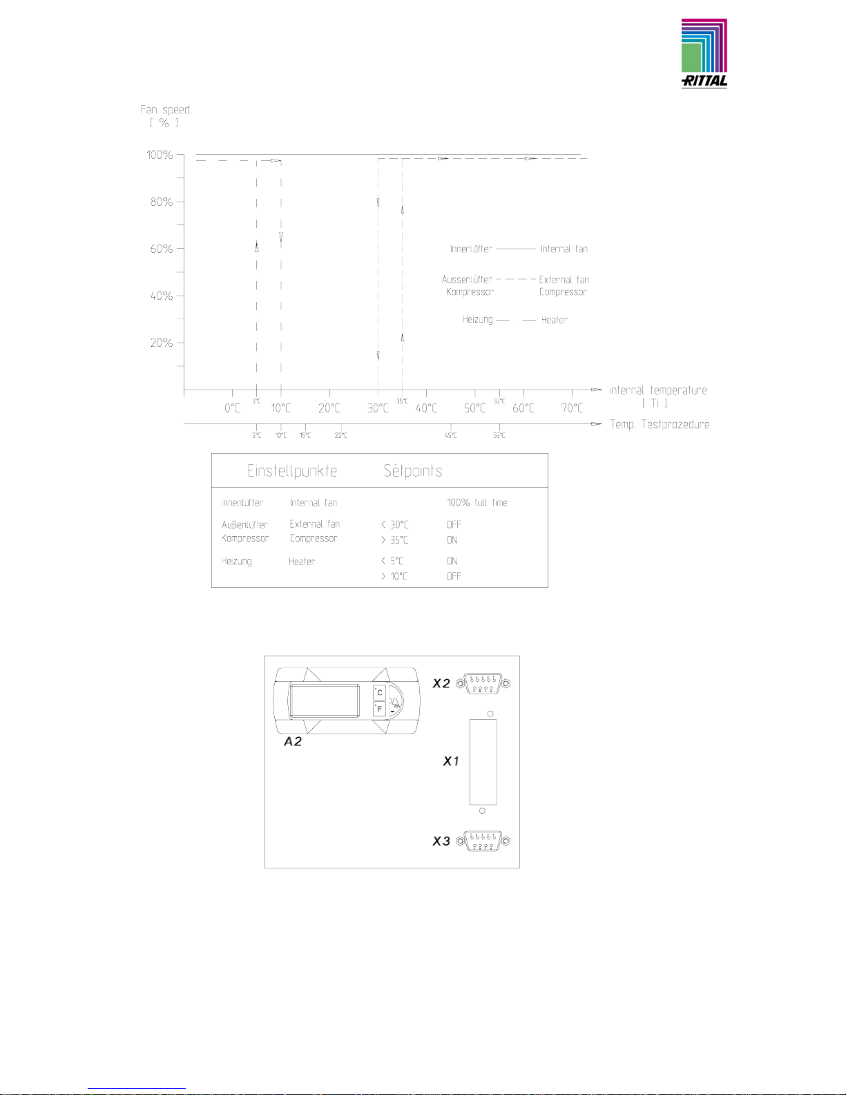
Abb. 4.1 Funktionsdiagramm Fig. 4.1 Functional diagram
Abb. 4.2 Bedienfeld / Anschlussfeld Fig. 6.2 Control panel / connector panel
A2 = Anzeigeterminal A2 = Display terminal
X1 = Hauptanschlussklemmleiste X1 = Main terminal strip
X2 = Master/Slave-Anschluss X2 = Master/slave connection
X3 = Optionale Schnittstelle X3 = Optional interface
Page 7
_______________________________________________________________________________________
Montageanleitung CS 9776.500 / 9774.250 / 9774.450 11-2005 Technische Änderungen vorbehalten
Assembly instructions CS 9776.500 / 9774.250 / 9774.450 11-2005 Technical modifications reserved
5. Comfortcontroller-Regelung 5. Comfort controller control
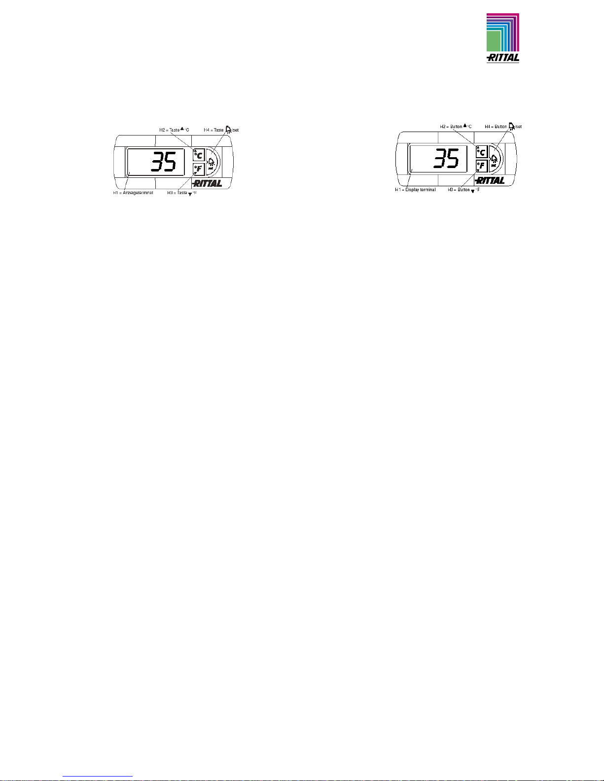
Abb. 5.1 Comfortcontroller Fig. 5.1 Comfort controller
5.1 Bedienung des Comfortcontrollers
(s. a. Diagramm 13.1 Programmierung)
5.1 Operation of the Comfort controller
(see diagram 13.1 Programming)
Das Anzeigeterminal H1 enthält eine dreistellige 7Segment-anzeige zur Temperaturanzeige in °C oder
°F umschaltbar sowie zur Anzeige der Fehlercodierung. Die aktuelle Schaltschrank-Innentemperatur
wird permanent an H1 angezeigt. Bei Auftreten einer
Systemmeldung erscheint diese alternierend zur aktuellen Schaltschrank-Innentemperatur im Display.
Bei der Programmierung des Gerätes erfolgt die Anzeige der Programmierlevels und des Vorgabewertes
ebenfalls über die Anzeige.
The display terminal H1 consists of a 3 position 7segment display which indicates the internal enclosure temperature in °C or °F (changeable) as well as
any fault codes. The actual enclosure internal temperature is constantly displayed on H1. When a system message is generated, this alternates in the display with the current internal enclosure temperature.
While programming the unit, the programming level
and prescribed value are also displayed.
Testmodus
Durch gleichzeitiges Drücken der Tasten H2 (Taste
▲°C) und H4 (Taste
A /set) für 5 sec. nimmt das
Kühlgerät unabhängig vom Sollwert den Kühlbetrieb
auf. Die Türendschalterfunktion bleibt hierbei unberücksichtigt. Nach ca. 5 min. bzw. beim Erreichen von
15°C schaltet das Gerät den Kühlbetrieb wieder ab.
Test mode
By simultaneously holding down keys H2
(▲°C key) and H4 (
A /set key) for 5 seconds, the
cooling unit will commence cooling operation, irrespective of the setpoint. The door limit switch function
is disregarded in such cases. After approximately 5
minutes or upon reaching 15°C the device deactivates cooling operation once again.
5.2 Programmierung
(s.a. 13. Programmierung des Comfortcontrollers)
5.2 Programming
(see 13. Comfort controller programming)
Im EEPROM der Comfortregelung sind verschiedene
Parameter gespeichert, die über Programmierung der
Taste H2, H3 und H4 geändert werden können. 24
veränderbare Parameter sind über 24 ProgrammLevels und in den vorgegebenen Bereichen (max.
und min. Werte) veränderbar. Hierzu ist der EingabeCode „22“ erforderlich (s.a. Diagramm 13.1)
Die Tasten H2, H3 und H4 sind mehrfachbelegt. Um
in den Programmiermodus zu gelangen ist set 5 sec.
gedrückt zu halten. Primärbelegung (nur Anzeige der
Dioden):
H2: °C, H3: °F, H4: Alarm
Sekundärbelegung (zur Programmierung):
H2: Pfeil nach oben, H3: Pfeil nach unten, H4: set
In the EEPROM of the Comfort controller various
parameters are stored which can be changed by using the buttons H2, H3 and H4. 24 changeable parameters can be set via 24 programme levels in the
stated ranges (max. and min. values). To this end,
input code “22” is required (see diagram 13.1)
The H2, H3 and H4 keys are multiple occupancy. To
access programming mode, set 5 sec is to be
pressed and held down. Primary occupancy (only
diode displays):
H2: °C, H3: °F, H4: Alarm
Secondary occupancy (for programming):
H2: Arrow upwards, H3: Arrow downwards, H4: set
Page 8

_______________________________________________________________________________________
Montageanleitung CS 9776.500 / 9774.250 / 9774.450 11-2005 Technische Änderungen vorbehalten
Assembly instructions CS 9776.500 / 9774.250 / 9774.450 11-2005 Technical modifications reserved
5.3 Systemmeldeeinrichtung 5.3 System messaging equipment
Alle Systemmeldungen am Kühlgerät werden erfasst
und als Fehlernummer von H1 angezeigt. Die Systemmeldungen erscheinen alternierend zur aktuellen
Schrank-Innentemperatur.
Es besteht auch die Möglichkeit die Systemmeldungen bei Vorwahl 0 nur am Displayanzuzeigen.
(s.a. 12. Displayanzeige und Fehleranalyse der
Comfortregelung).
All system messages at the cooling unit are recorded
and displayed as an error number by H1. System
messages alternate in the display with the current
internal enclosure temperature.
Another option is to have the system alarm shown at
the display only when 0 is selected.
(see 12. Comfort control fault display and error analysis).
5.4 Systemmelde-Kontakt
(K1 und K2; Platine)
5.4 System message contact
(K1 and K2; PCB)
Alle Störungen sind im Programm, Relais 2 zugeordnet, welches über ein Koppelrelais potentialfrei auf
die Klemmen verdrahtet ist.
Relais 1 schaltet die zusätzliche Heizung
(ein <+5°C, aus >+10°C).
Das Koppelrelais ist im Betrieb angezogen, Klemme
4 und 5 geschlossen. Alle dem Relais zugeordneten
Störungen führen zum Abfallen des Koppelrelais. Ein
Ausfall der Steuerspannung führt ebenfalls zum Abfallen des Relais und kann somit erfasst und im Logfile dokumentiert werden.
Der Anschluss erfolgt an der Klemmleiste X1 Klemme 3,4,5.
Potentialfreier Wechsler
Klemme 3: Störung
Klemme 4: gemeinsamer Anschluss
Klemme 5: Betrieb
(s.a. Schaltplan)
All faults are assigned to relay 2 in the programme,
which is wired floating to the terminal via a switching
relay.
Relay 1 switches the additional heater
(on <+5°C, off >+10°C).
The switching relay is tightened during operation,
terminals 4 and 5 are closed. All faults assigned to
the relay result in a drop in the switching relay. A failure of the control voltage also leads to a drop in the
relay and therefore can be detected and documented
in the log file.
The connection occurs to the terminal strip X1 terminals 3,4,5.
Floating changeover contact
Terminal 3: Fault
Terminal 4: Joint connection
Terminal 5: Operation
(also s. wiring )
6. Zusatzfunktionen 6. Supplementary functions
6.1 Türendschalter S1 (Kundenbeistellung) 6.1 Door limit switch S1 (supplied by customer)
Bei Verwendung eines Türendschalters und geöffneter Schranktür (Kontakt bei geöffneter Tür geschlossen), wird das Kühlgerät (Ventilatoren und Verdichter)
nach ca. 15 sec abgeschaltet. Damit wird ein erhöhter
Kondensatanfall bei geöffneter Tür vermieden. Um
einen Taktbetrieb zu vermeiden, wird das Wiedereinschalten von Verdichter und Außenventilator nach
Abschalten des Gerätes um ca. 3 min verzögert. Der
Innenventilator läuft nach dem Schließen der Tür
nach ca. 15 sec. wieder an. Der Anschluss erfolgt an
der Klemme 1 und 2. Die Kleinspannungsversorgung
erfolgt vom internen Netzteil; Strom ca. 30 mA DC.
Jeder Türendschalter darf nur einem Gerät zugewiesen werden. An einem Kühlgerät können mehrere
Türendschalter betrieben werden (Parallelschaltung).
Der minimale Querschnitt der Anschlussleitung beträgt 0,3 mm
2
bei einer Kabellänge von 2 m. Der Widerstand des Türendschalterkontaktes darf max.
50 Ω betragen
Türendschalter sind nur potentialfrei anzuschließen, keine externen Spannungen!
Where a door limit switch is used and the enclosure
door is open (contact is closed when door is open),
the cooling unit (fans and condenser) will switch off
after approx. 15 s, thereby avoiding an increase in
condensation while the door is open. To avoid cyclic
operation, switch-on of condenser and external fan is
delayed by about 3 minutes after the cooling unit has
been switched off.
The internal fan will start up after about 15 s on closure of the door. Connection is made at the terminals
1 and 2. The extra low voltage is supplied by the internal power pack, current is approx. 30 mA DC.
Each door limit switch must only be assigned to one
cooling unit. Several door limit switches may be operated on one cooling unit (parallel connection). The
minimum cross-section of the connection cable is 0,3
mm
2
for a length of 2 m. The resistance of the door
limit switch contact must not exceed a maximum of
50 Ω.
Connect the door limit switch free from potential
only, no external voltage!
Page 9

_______________________________________________________________________________________
Montageanleitung CS 9776.500 / 9774.250 / 9774.450 11-2005 Technische Änderungen vorbehalten
Assembly instructions CS 9776.500 / 9774.250 / 9774.450 11-2005 Technical modifications reserved
6.2Schnittstelle X3 (Option)
(Stecker X3)
6.2 Interface X3 (Option)
(Connector X3)
Achtung!
Bei den elektrischen Signalen an der Schnittstelle
handelt es sich um Kleinspannungen (nicht um Sicherheitskleinspannungen nach EN 60 335).
An der 9poligen SUB-D-Stecker X3 können zusätzliche Schnittstellenkarten zur Einbindung der Kühlgeräte in übergeordnete Überwachungssysteme angeschlossen werden. Diese Karten sind auch als Zubehör erhältlich.
(Best.-Nr.: Schnittstellenkarte SK 3124.200)
Note!
The electrical signals at the interface are of an extralow voltage (not extra-low safety voltages to EN 60
335).
The 9-pin SUB-D socket X3 can be used to connect
additional interface cards for integrating cooling units
with higher level monitoring systems.
These cards are also available as an accessory.
(Model No.: Interface card SK 3124.200).
7. BUS-System
(Best.-Nr.: Master-Slave-Kabel SK 3124.100)
7. BUS system
(Model No.: Master-slave cable SK
3124.100)
7.1 Allgemeines 7.1 General
Mit dem BUS-System werden Verbindungen zwischen maximal 10 Kühlgeräten hergestellt.
Der Bediener erhält damit folgende Funktionen:
• Parallele Gerätesteuerung (gemeinsames Ein-
und Ausschalten der vernetzten Kühlgeräte)
• Parallele Türmeldung (Tür auf)
• Parallele Sammelstörmeldung
Der Datenaustausch erfolgt über das Master-SlaveKabel (abgeschirmte, zweiadrige Leitung). Alle Geräte erhalten eine Adresse. Sie enthält auch die Kennung „Master“ oder „Slave“.
The BUS system allows a maximum of 10 cooling
units to be interconnected.
As a result, the following functions are available to the
operator:
• Parallel unit control (the cooling units in the net-
work can be simultaneously switched on and off)
• Parallel door status messages (“door open”)
• Parallel collective fault message
The data exchange is carried out using master-slave
cables (shielded, two-wire leads). All units are assigned an address. This address also includes the ID
for “master” or “slave”.
7.2 Installationshinweise an
Schnittstelle X2 ( Buchse X2)
7.2 Installation notices for the X2 interface
(Jack X2)
Achtung!
Bei den elektrischen Signalen an der Schnittstelle
handelt es sich um Kleinspannungen (nicht um
Sicherheitskleinspannungen nach EN 60 335).
Folgende Hinweise unbedingt beachten!
• Zu verbindende Kühlgeräte spannungsfrei schal-
ten.
• Auf ausreichende elektrische Isolierung achten.
• Kabel nicht parallel zu Netzleitungen verlegen.
• Auf kurze Leitungswege achten.
Note!
The electrical signals at the interface are of an extralow voltage (not extra-low safety voltages to
EN 60 335).
Always heed the following notes!
• De-energise the cooling units to be connected.
• Ensure proper electrical insulation.
• Make sure the cables are not laid in parallel to
power lines.
• Make sure that the lines are short.
Page 10
_______________________________________________________________________________________
Montageanleitung CS 9776.500 / 9774.250 / 9774.450 11-2005 Technische Änderungen vorbehalten
Assembly instructions CS 9776.500 / 9774.250 / 9774.450 11-2005 Technical modifications reserved
7.3 Programmierung des Kühlgerätes 7.3 Programming the cooling unit
Programmierung siehe Diagramm 13 See diagram 13 for details on programming.
Kennung: IDs
Master-Kühlgerät Slave-Kühlgerät Master cooling unit Slave cooling unit
00 Grundzustand 00 Grundzustand 00 Basic state 00 Basic state
01 Master mit 1 Slave 11 Slave mit Adresse 1 01 Master with 1 Slave 11 Slave with address 1
02 Master mit 2 Slave 12 Slave mit Adresse 2 02 Master with 2 Slave 12 Slave with address 2
03 Master mit 3 Slave 13 Slave mit Adresse 3 03 Master with 3 Slave 13 Slave with address 3
04 Master mit 4 Slave 14 Slave mit Adresse 4 04 Master with 4 Slave 14 Slave with address 4
05 Master mit 5 Slave 15 Slave mit Adresse 5 05 Master with 5 Slave 15 Slave with address 5
06 Master mit 6 Slave 16 Slave mit Adresse 6 06 Master with 6 Slave 16 Slave with address 6
07 Master mit 7 Slave 17 Slave mit Adresse 7 07 Master with 7 Slave 17 Slave with address 7
08 Master mit 8 Slave 18 Slave mit Adresse 8 08 Master with 8 Slave 18 Slave with address 8
09 Master mit 9 Slave 19 Slave mit Adresse 9 09 Master with 9 Slave 19 Slave with address 9
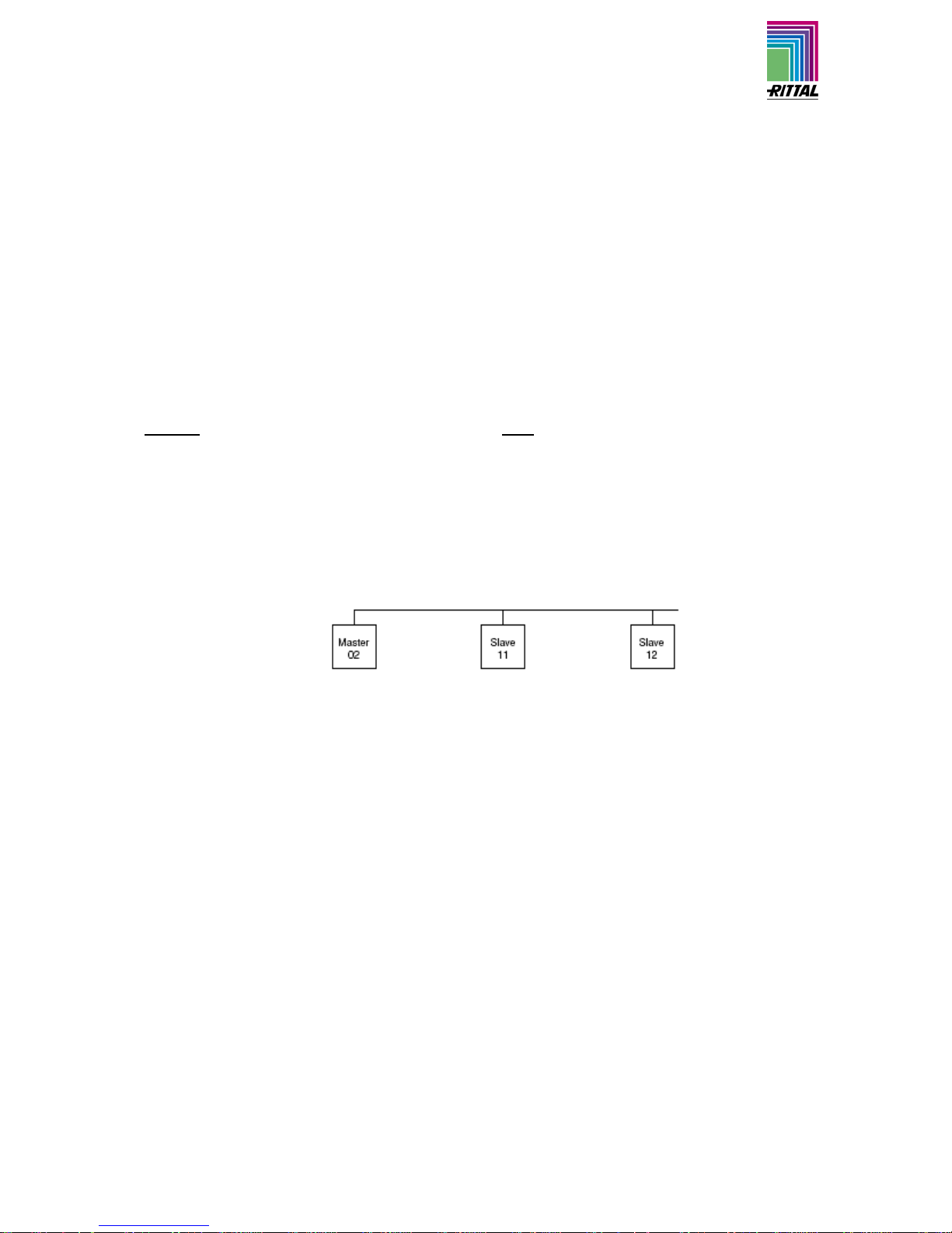
Hinweis
Es darf nur ein Gerät als Master konfiguriert werden
und die Adresskennung muss mit der Anzahl der
Slave-Geräte übereinstimmen. Alle Slave-Geräte
müssen unterschiedliche Adressen haben und die
Adressen müssen aufsteigend ohne Lücken sein.
Beispiel:
1 Master-Kühlgerät mit 2 Slave-Kühlgeräten
Note
Only one unit may be configured as master; the address ID must match the number of slave units. The
individual slave units must have different addresses;
the addresses must be in ascending
order (without gaps in between).
Example:
1 master cooling unit with 2 slave cooling units
7.4 Filtermattenüberwachung
(Gerät verfügt über keine integrierte Filte rmatte)
7.4 Filter mat monitoring
(Unit does not have a integrated filter mat)
Page 11

_______________________________________________________________________________________
Montageanleitung CS 9776.500 / 9774.250 / 9774.450 11-2005 Technische Änderungen vorbehalten
Assembly instructions CS 9776.500 / 9774.250 / 9774.450 11-2005 Technical modifications reserved
Abb. 7.1 Wirkschaltplan Fig. 7.1 Detailed wiring diagram
A1 = Leistungsplatine A1 = Power PCB
A2 = Anzeigeterminal A2 = Display terminal
B1 = Temperaturfühler Innentemperatur B1 = Internal temperature sensor
B2 = Temperaturfühler Vereisungsschutz B2 = Icing hazard temperature sensor
B3 = Temperaturfühler außen 1 (Verflüssiger) B3 = Temperature sensor, external 1 (Condenser)
B4 = Temperaturfühler außen 2 (Umgebung) B4 = Temperature sensor, external 2 (Ambience)
B5 = Kondensatsensor (kein Sensor, sondern Brücke) B5 = Condensate sensor (no sensor, but a bridge)
C2 = Betriebskondensator C2 = Operating capacitor
C4 = Betriebskondensator C4 = Operating capacitor
F2 = HD-Wächter F2 = HP monitor
F3 = Thermokontakt Verdichter F3 = Compressor thermal contact
Hz = Heizelement mit Temperaturbegrenzer Hz = Thermal element with temperature limit
Kx = Relais K1 Heizung Kx = Relay K1 heater
Kx = Relais K2 Sammelstörung Kx = Relay K2 collective fault
K3 = Koppelrelaismeldung K3 = Coupling relay alarm signal
M1 = Verdichter mit Wannenheizung M1 = Compressor with heater
M2 = Verflüssigerventilator (Innenlüfter) M2 = Condenser fan (Internal fan)
M4 = Verdampferventilator (Außenlüfter) M4 = Evaporator fan (external fan)
S1 = Türendschalter
(ohne Türendschalter Klemme 1, 2 offen)
S1 = Door limit switch
(without door operated switch terminal 1, 2 open)
X1 = Hauptanschlussklemmleiste X1 = Main terminal strip
X2 = Master/Slave-Anschluss X2 = Master/slave connection
X3 = Optionale Schnittstelle X3 = Optional interface
Page 12

_______________________________________________________________________________________
Montageanleitung CS 9776.500 / 9774.250 / 9774.450 11-2005 Technische Änderungen vorbehalten
Assembly instructions CS 9776.500 / 9774.250 / 9774.450 11-2005 Technical modifications reserved
8. Technische Information 8. Technical information
Das Kühlgerät (Kompressionskälteanlage) besteht
aus vier Hauptteilen:
• Kältemittelverdichter (Kompressor),
• Verdampfer,
• Verflüssiger (Kondensator)
• und dem Regel- bzw. Expansionsventil,
die durch entsprechende Rohrleitungen verbunden
sind. Dieser Kreislauf ist mit einem leicht siedenden
Stoff, dem Kältemittel aufgefüllt. Das Kältemittel
R134a (CH
2
FCF3) ist chlorfrei. Sein Ozon-Zerstörungs-Potential (OZP) beträgt 0. Es ist somit sehr
umweltfreundlich. Ein Filtertrockner, der in den hermetisch geschlossenen Kältekreislauf integriert ist,
bietet wirksamen Schutz gegen Feuchtigkeit, Säure,
Schmutzteilchen und Fremdkörper im Inneren des
Kältekreislaufes.
The cooling unit (compression refrigeration unit) consists of four main components:
• coolant compressor,
• evaporator,
• condenser
• and the control expansion valve,
which are connected by suitable pipework. This circuit
is filled with a readily boiling substance, the coolant.
The R134a (CH
2
FCF3) coolant is free from chlorine. It
has an ozone destroying potential (ODP) of 0 and is
therefore environmentally friendly. A filter dryer which
is integrated in the hermetically sealed cooling circuit,
provides effective protection against moisture, acid,
dirt particles, and foreign bodies within the cooling
circuit.
8.1 Arbeitsweise des Kühlgerätes 8.1 Operation of the Cooling Unit
Abb. 8.1 Funktionsprinzip Fig. 8.1 Cooling Circuit
Der Kältemittelverdichter saugt gasförmiges Kältemittel aus dem Verdampfer ab und koprimiert es
auf einen höheren Druck im Verflüssiger. Dabei steigt
die Kältemitteltemperatur über die Umgebungstemperatur an, so dass Wärme über die Fläche des luftbaufschlagten Verflüssigers an die Umgebung abgegeben wird. Bei diesem Vorgang verflüssigt sich das
Kältemittel und wird nun über ein thermostatisches
Expansionsventil in den Verdampfer eingespritzt, wo
es bei niedrigerem Druck verdampft. Die zum vollständigen Verdampfen benötigte Wärme wird der
Schrankluft entzogen und bewirkt dessen Abkühlung.
Damit ist der Kältemittelkreislauf geschlossen und der
vorgenannte Arbeitsvorgang der Wärmeübertragung
beginnt erneut.
The compressor extracts the gaseous refrigerant
from the evaporator and compresses it to a higher
pressure in the condenser. During this process the
temperature of the refrigerant rises above the ambient temperature and heat is dissipated to the environment via the surface of the condenser. Then the
refrigerant is liquefied and, by means of a thermostatically controlled expansion valve, returned to the
evaporator, where it evaporates at low pressure. The
heat required for complete evaporation is drawn from
the enclosure interior causing it to cool down. The
cooling cycle is thus completed, the aforementioned
process of the heat transfer starts afresh.
Page 13

_______________________________________________________________________________________
Montageanleitung CS 9776.500 / 9774.250 / 9774.450 11-2005 Technische Änderungen vorbehalten
Assembly instructions CS 9776.500 / 9774.250 / 9774.450 11-2005 Technical modifications reserved
8.2 Sicherheitseinrichtungen 8.2 Safety equipment
Das Kühlgerät besitzt im Kältekreislauf einen bauteilgeprüften Hochdruckwächter nach EN 12 263, der
auf max. Betriebsdruck eingestellt ist und durch eine
automatische Rückstelleinrichtung bei wiedereintretendem Druckabfall arbeitet.
Ein Vereisen des Verdampfers wird durch Temperaturüberwachung bzw. Niederdrucküberwachung verhindert. Bei Vereisungsgefahr wird der Verdichter
abgeschaltet und bei höheren Temperaturen automatisch wieder eingeschaltet. Der Kältemittelvedichter sowie die Ventilatoren sind zum Schutz gegen
Überstrom und Übertemperatur mit thermischen
Wicklungsschutzschaltern ausgestattet.
The cooling circuit of the cooling unit embodies a
component tested high-pressure monitor to
EN 12 263 which is set to maximum operating pressure and operates via an automatic reset device at
recurring pressure drop.
Temperature and low-pressure monitoring will prevent the evaporator from icing up. If there is a risk of
icing up, the compressor is switched off and automatically switched on again at higher temperatures.
The refrigerant compressor and the fans are
equipped with thermal winding protection switches
against excess current and excess temperatures.
8.3 Kondensatablauf 8.3 Condensate discharge
Das Kühlgerät ist mit einem automatischen Kondensatablauf ausgerüstet. Eventuell entstehendes Kondensatwasser, welches sich am Verdampfer bilden
kann (bei hoher Luftfeuchtigkeit, niedrigen Schrank
innentemperaturen), sammelt sich im unteren Teil
des Kühlgerätes und tropft in den Außenkreislauf. Ein
separater Schlauchanschluß ist nicht erforderlich.
The cooling unit has an automatic condensate discharge. Condensate which may occur at the evaporator (in the event of high air humidity, low internal
enclosure temperatures) is collected at the bottom
section of the unit and discharged into the external
circuit. A separate hose is not required.
8.4 Allgemeines 8.4 General
Lagertemperatur:
Die Kühlgeräte dürfen während der Lagerung
Temperaturen über +70°C nicht ausgesetzt
werden.
Transportlage:
Die Kühlgeräte müssen immer stehend bis
max. waagrecht transportiert werden.
Entsorgung:
Der geschlossene Kältekreislauf enthält Kältemittel und Öl, die zum Schutz der Umwelt
fachgerecht entsorgt werden m
üssen
.
Die Entsorgung kann im Rittal-Werk durchgeführt werden.
Storage temperature:
The cooling units must not be exposed to
temperatures above +70°C during storage.
Transport position:
The cooling units must always be transported
in an upright to horizontal position.
Disposal:
The closed cooling circuit contains refrigerant
and oil which must be correctly disposed of in
order to protect the environment. Disposal
may be carried out at the Rittal works.
Page 14

_______________________________________________________________________________________
Montageanleitung CS 9776.500 / 9774.250 / 9774.450 11-2005 Technische Änderungen vorbehalten
Assembly instructions CS 9776.500 / 9774.250 / 9774.450 11-2005 Technical modifications reserved
9. Wartung 9. Maintenance
Achtung: Vor Wartungsarbeiten ist das Kühlgerät
einspeisungsseitig spannungsfrei zu schalten.
• Reinigungs-, Wartungs- und Reparaturarbeiten am Gerät dürfen nur durch autorisiertes
Fachpersonal ausgeführt werden.
Der Kältekreislauf, als wartungsfreies hermetisch
geschlossenes System, ist werksseitig mit der erforderlichen Kältemittelmenge gefüllt und auf Dichtigkeit
geprüft bzw. einem Funktionsprobelauf unterzogen
worden. Die eingebauten wartungsfreien Ventilatoren
sind kugelgelagert, feuchtigkeits- und staubgeschützt
und mit einem Temperaturwächter ausgestattet. Die
Lebensdauererwartung beträgt min. 30,000 Betriebsstunden. Das Kühlgerät ist damit weitgehend wartungsfrei.
Lediglich die Komponenten des äußeren Luftkreislaufes können je nach Schmutzanfall, von Zeit zu Zeit
mit Hilfe von Preßluft gereinigt werden. Die Verwendung einer Filtermatte als Schutz vor Verstopfen des
Verflüssigers ist nur bei groben Flusen in der Luft
sinnvoll.
• Es dürfen nur Original-Ersatzteile verwendet wer-
den.
• Nach allen Arbeiten müssen sowohl der Korrosi-
onsschutz, als auch alle Dichtungen auf Beschädigungen überprüft und wenn nötig ausgebessert
bzw. ausgetauscht werden.
Caution: Prior to any maintenance work, the
cooling unit must be switched free from potential
on the supply side.
• Cleaning, maintenance and repair work to the
unit must only be carried out by authorised,
trained staff.
As a maintenance-free, hermetically sealed system,
the cooling circuit has been filled in the factory with
the required amount of refrigerant, tested for leaks
and/or subjected to a functional trial run. The installed
maintenance-free fans run in ball races, they are
protected from moisture and dust, and are fitted with
a temperature monitor. The life expectancy is at least
30,000 operating hours. The cooling unit is thus
largely maintenance-free.
All that may be required from time to time is that the
components of the external circuit are cleaned by
compressed air. The use of a filter mat is recommended only if large particles of lint are present in the
air, so that blockage of the condenser is prevented.
• Only original spare parts must be used.
• Following all work, both the anti-corrosion protec-
tion and all seals must be checked for damage
and repaired or replaced as necessary.
10. Lieferumfang 10. Scope of supply
CS 9774.250 / CS 9774.450
• 1 Gehäuse mit montiertem Kühlgerät, maximale
Einbauposition
CS 9774.500
• 1 St. Kühlgerät anschlußfertig, mit tiefenjustierba-
rem Montagerahmen
• 1 St. Dichtprofil
• 16 St. Befestigungsschrauben mit Scheibe
• 1 St. Montageanleitung
CS 9774.250 / CS 9774.450
• 1 Enclosure with mounted cooling unit, maximum
depth in the enclosure
CS 9774.500
• 1 pcs. Heat-exchanger unit, ready for connection,
with justable mounting frame
• 1 pcs. Sealing profile
• 16 pcs. Mounting screws with washer
• 1 pcs. Assembly instruction
Page 15

_______________________________________________________________________________________
Montageanleitung CS 9776.500 / 9774.250 / 9774.450 11-2005 Technische Änderungen vorbehalten
Assembly instructions CS 9776.500 / 9774.250 / 9774.450 11-2005 Technical modifications reserved
11. Ersatzteile 11. Spare parts
Bezeichnung ID-Nr.: Description Part Nr.:
1. Innenkreislüfter 287 997 1. Internal circuit fan 287 997
2. Außenkreislüfter 287 996 2. External circuit fan 287 996
3. Rohrkreiskörper 287 999 3. Heating element 287 999
4. Temperaturfühler Ti 4. Temperature sensor Ti
5. Temperaturfühler Tver 5. Temperature sensor Tver
6. Platine 289 381 6. PCB 289 381
7. Kompressor 288 006 7. Compressor 288 006
8. Filtertrockner 219 016 8. Fillter dryer 219 016
9. Expansionsventil 9. Expansion valve
10. Verdampfer 288 002 10. Evaporator 288 002
11. Verflüssiger 288 001 11. Condenser 288 001
Bei Bestellung unbedingt angeben: Absolutely necessary in case of order:
Artikelnummer des Kühlgerätes:
Fabrikationsnummer:
Herstellnummer:
Ersatzteilnummer:
Type of heat-exchanger unit:
Fabrication no.:
Manufacturing date:
Spare part no.:
Page 16

Montageanleitung CS 9776.500 / 9774.250 / 9774.450 11-2005 Technische Änderungen vorbehalten
Assembly instructions CS 9776.500 / 9774.250 / 9774.450 11-2005 Technical modifications reserved
12. Displayanzeige und Systemanalyse der Comfortregelung 12. Comfort control display screen and system analysis
Alarm Nr.
Alarm no.
Systemmeldung
System message Loads
Ursache
Cause
Abhilfe
Remedy
Heizung
Heater
Verdichter
Compressor
Verflü ssigerventilator
Condenser fan
Verdampfer-
ventilator
Evaporator fan
A01 Schaltschranktür offen
Enclosure door open
AUS nach 15 sek.
OFF after 15 sec
Tür geöffnet oder Türendschalter nicht korrekt positioniert
Door open or door limit switch not correctly positioned
Tür schließen, Türendschalter korrekt positionieren, ggf.
Anschluss überprüfen
Close door, position door limit switch correctly, check connection if necessary
A02 Schaltschrank-
Innentemperatur zu hoch
Internal temperature of
enclosure too high
Nicht verfügbar
Not applicable
Kühlleistung zu gering/Gerät unterdimensioniert
Folgefehler der Meldungen A03 bis A17
Cooling capacity too low/unit undersized
Sequence errors in messages A03 to A17
Kühlleistung prüfen
Check cooling capacity
A03 (*) Filterüberwachung
Filter monotoring
Nicht verfügbar
Not applicable
Filtermatte verschmutzt
Filter mat soiled
Reinigen oder Austausch
Clean or exchange
A04 Umgebungstemperatur
zu hoch / zu niedrig
Ambient temperature too
high/too low
Nicht verfügbar
Not applicable
Umgebungstemperatur ausserhalb des zulässigen Betriebsbereiches (+10°C bis +60°C)
Ambient temperature outside the permissible operating
range (+10°C to +60°C)
Umgebungstemperatur anheben oder absenken ( z.B. heizen
oder belüften )
Raise or lower the ambient temperature
(e.g. heat or ventilation)
A05 Vereisungsgefahr
Icing hazard
Nicht verfü gbar
Not applicable
AUS
OFF
Nicht verfü gbar
Not applicable
Betriebsmäßige Anzeige bei Vereisungsgefahr
Icing hazard display according to operating mode
Sollwert Schrankinnentemperatur höher einstellen
Increase the nominal value of the internal enclosure temperature
Nicht verfü gbar
Not applicable
AUS
OFF
Nicht verfü gbar
Not applicable
Umgebungstemperatur zu hoch
Ambient temperature too high
Geräteeinsatzgrenze überschritten
Unit operating limits exceeded
Filtermatte verschmutzt
Filter mat soiled
Verflüssiger verschmutzt
Condenser soiled
Reinigen oder Austausch
Clean or exchange
Reinigen
Clean
Verflüssigerventilator defekt
Condenser fan defective
Austausch
Exchange
E-Ventil defekt
E-valve defective
Reparatur durch Kältetechniker
Repair by refrigeration engineer
A06 (*) HD-Wächter
HP monitor
HD-Wächter defekt
HP monitor defective
Austausch durch Kältetechniker
Refrigeration engineer to exchange
A07 (*) Verdampfer
Evaporator
Nicht verfü gbar
Not applicable
AUS
OFF
Nicht verfü gbar
Not applicable
Kältemittelmangel
Refrigerant fault
Reparatur durch Kältetechniker
Repair by refrigeration engineer
A08 Kondensatwarnung
Condensate warning
Nicht verfü gbar
Not applicable
AUS
OFF
Nicht verfü gbar
Not applicable
Nur bei Geräten mit optionaler Kondensatverdunstung
Only in units with optional condensate evaporation
Kondensatablauf überprüfen; evtl. Knicke oder Verstopfungen
im Schlauch beseitigen
Check condensate drainage; repair kinks or blockages in the
hose as necessary
A09 Verflüssigerventilator
Condenser fan
Nicht verfü gbar
Not applicable
AUS
OFF
Nicht verfü gbar
Not applicable
Blockiert oder defekt
Blocked or defective
Blockade beseitigen; ggf. Austausch
Clear the blockage; exchange if necessary
A10 Verdampferventilator
Evaporator fan
AUS
OFF
Blockiert oder defekt
Blocked or defective
Blockade beseitigen; ggf. Austausch
Clear the blockage; exchange if necessary
Page 17

Montageanleitung CS 9776.500 / 9774.250 / 9774.450 11-2005 Technische Änderungen vorbehalten
Assembly instructions CS 9776.500 / 9774.250 / 9774.450 11-2005 Technical modifications reserved
Alarm Nr.
Alarm no.
Systemmeldung
System message Loads
Ursache
Cause
Abhilfe
Remedy
Heizung
Heater
Verdichter
Compressor
Aussen-
lüfter
External fan
Innenlüfter
Internal fan
A11 Verdichter
Compressor
Nicht verfü gbar
Not applicable
AUS
OFF
Nicht verfü gbar
Not applicable
Verdichter überlastet (interner W icklungsschutz)
Compressor overloaded (internal winding protection)
Gerät schaltet selbständig wieder ein
Unit switches on again automatically
blockiert
blocked
Defekt
(durch Widerstandsmessung der Wicklung prüfen)
Defective
(check by measuring the winding resistance)
Austausch durch Kältetechniker
Exchange by refrigeration engineer
A12 Temperaturfühler Ver-
flüssiger
Condenser temperature
sensor
Nicht verfü gbar
Not applicable
AUS
OFF
Nicht verfü gbar
Not applicable
Leitungsbruch oder Kurzschluß
Open or short circuit
Austausch
Exchange
A13 Temperaturfühler Umge-
bungstemperatur
Ambient temperature
sensor
Nicht verfü gbar
Not applicable
AUS
OFF
Nicht verfü gbar
Not applicable
Leitungsbruch oder Kurzschluß
Open or short circuit
Austausch
Exchange
A14 Temperaturfühler Verei-
sung
Icing temperature sensor
Nicht verfü gbar
Not applicable
AUS
OFF
Nicht verfü gbar
Not applicable
Leitungsbruch oder Kurzschluß
Open or short circuit
Austausch
Exchange
A15 Temperaturfühler Kon-
densatwarnung
Condensate temperature
warning
Nicht verfü gbar
Not applicable
AUS
OFF
Nicht verfü gbar
Not applicable
Leitungsbruch oder Kurzschluß
Open or short circuit
Austausch
Exchange
A16 Temperaturfühler Innen-
temperatur
Internal temperature
sensor
AUS
OFF
Nicht verfü gbar
Not applicable
Leitungsbruch oder Kurzschluß
Open or short circuit
Austausch
Exchange
A17 Phasenüberwachung
Phase monitoring
AUS
OFF
Falsches Drehfeld / Phase fehlt
Incorrect rotary field / phase absent
Zwei Phasen tauschen
Exchange two phases
A18 Eprom Fehler
EPROM error
AUS
OFF
A19 LAN / Master – Slave
LAN / Master – Slave
Nicht verfügbar
Not applicable
Master und Slave nicht verbunden
Master and Slave not connected
Einstellung bzw. Kabel überprüfen
Check setting or cable
A20 Spannungsabfall
Voltage drop
- - - - Störanzeige wird nicht dargestellt
Fault display is not illustrated
Event wird im Log file gespeichert
Event is saved in the log file
E0 Displaymeldung
Display message
Nicht verfügbar
Not applicable
Verbindungsproblem zwischen Display und Regelplatine
Connection problem between display and circuit board
Steckverbinder lose, Kabel defekt, ggf. Display / Platine tauschen
Connector detached, cable damaged, if necessary change display / circuit board
* Die Störanzeigen A03, A06 und A07 sind manuell zu reseten.
Dazu sind die Tasten ▲. und ▼. gleichzeitig für 5 sec. gedrückt zu halten.
* The fault displays A03, A06 and A07 are to be reset manually.
To do this, hold down the ▲ and ▼ keys simultaneously for 5 seconds.
Alle Systemmeldungen werden alternierend mit der Innentemperatur angezeigt,
außer den Meldungen für Hochdruck-Alarm und „Innentemperaturfühler defekt“.
All the signallings are alternate with internal temperature, except high pressure alarm
and internal temperature sensor broken alarm.
Page 18

Montageanleitung CS 9776.500 / 9774.250 / 9774.450 11-2005 Technische Änderungen vorbehalten
Assembly instructions CS 9776.500 / 9774.250 / 9774.450 11-2005 Technical modifications reserved
13. Programmierung der Comfortregelung 13. Comfort control programming
Ebene
Level
Display-
anzeige
Display
screen
veränderbare
Parameter
changeable
parameter
min.
Wert
min.
value
max.
Wert
max.
value
Werksein-
stellung
Factory
setting
Erklärung
Explanation
1St
Sollwert SchaltschrankInnentemperatur Ti
Nominal value of the
internal enclosure
20 55
35 Der Sollwert der Schaltschrank-Innentemperatur ist werksseitig auf 35 °C
eingestellt und in dem Bereich von 20 °C bis 55 °C veränderbar.
The nominal value of the internal enclosure temperature is set at
the factory to 35 °C and is variable over a 20 °C range to 55 °C.
2 Fi Filtermattenüber-
wachung
Filter mat monitoring
10 60
(99 = off)
99
Zur Aktivierung der Filtermattenüberwachung ist die Anzeige auf
mind. 10 K über den im Programmiermodus „Fi“ angezeigten Temperaturdifferenzwert einzustellen; werksseitig ist die Filtermattenüberwachung ausgeschaltet. (Anzeige 99 = off).
For activation of filter mat monitoring, the display is to be set to a
minimum of 10 K above the temperature difference shown in programming mode “Fi”; filter mat monitoring is switched off at the
factory. (Display 99 = off).
3 Ad Master-Slave
Programmierung
Master-slave
programming
019
0
s. a. 8.3 „Programmierung des Kühlgerätes“
see 8.3 “Cooling unit programming”
4 CF Umschaltung °C/°F
Temperature conversion
0 1
0 Die Temperaturanzeige ist umstellbar von °C (0) auf °F (1). Die aktuelle
Temperatureinheit wird über die entsprechende LED angezeigt.
The temperature display can be switched from °C (0) to °F (1). The corresponding LED displays the current unit of temperature.
5 H1 Einstellung Schalt-
differenz
Temperature switching
210
5 Das Kühlgerät ist werksseitig auf eine Schalthysterese von 5K eingestellt.
Eine Veränderung diese Parameters sollte nur in Absprache mit dem
Hersteller erfolgen.
The cooling unit is set in the factory for a switching cycle of 5 K. This parameter
should only be changed after agreement with the manufacturer.
6 H2 Differenzwert der
Fehlermeldung 2
Difference for error
message 2
3 15
5 Steigt die Schaltschrank-Innentemperatur über 5 K des eingestellten
Sollwertes an, so erscheint die Fehlermeldung 2 (SchaltschrankInnentemperatur zu hoch) auf dem Anzeigeterminal. Im Bedarfsfall ist der
Differenzwert von 5 K im Bereich von 3 bis 15 K veränderbar.
If the internal enclosure temperature exceeds the set value by more than
5 K, then error message 2 (internal enclosure temperature too high)
appears on the display terminal. The difference of 5 K can be changed if
required over the range 3 K to 15 K.
7A1 02
0
8 A2 0 2
0
9A3 02
0
10 A4 0 2
0
11 A5 0 2
0
12 A6 0 2
2
13 A7 0 2
2
14 A8 0 2
2
15 A9 0 2
2
16 A10 0 2
2
17 A11 0 2
2
18 A12 0 2
2
19 A13 0 2
2
20 A14 0 2
2
21 A15 0 2
2
22 A16 0 2
2
23 A17 0 2
2
24 A18 0 2
0
25 A19
Zuschaltung Relais
Relay connection
02
0
Die im Display dargestellten Störmeldungen (A1 bis 19) werden
durch ein zusätzliches Störmelderelais ausgewertet.
Alle Störmeldungen werden durch das Relais 2 ausgewertet.
Entsprechend ist der Wert „2“ programmiert. Beim Wert „0“ wird die
Systemmeldung nur im Display visualisiert. Hiermit wird dem Anwender entsprechend ermöglicht, die Gewichtung der Systemmeldungen durch Aufteilung selbst zu definieren.
Über das Störmelderelais 1 wird die zusätzliche Heizung geschaltet.
The fault messages (A1 to 19) depicted in the display are evaluated
using an additional fault message relay. All fault messages are
evaluated via relay 2. The value “2” is to be programmed accordingly. If the value is set to “0”, the system message appears only in
the display. This accordingly enables the user to define the system
weighting himself.
The additional heater is switched via the fault signal relay 1.
Page 19

_______________________________________________________________________________________
Montageanleitung CS 9776.500 / 9774.250 / 9774.450 11-2005 Technische Änderungen vorbehalten
Assembly instructions CS 9776.500 / 9774.250 / 9774.450 11-2005 Technical modifications reserved
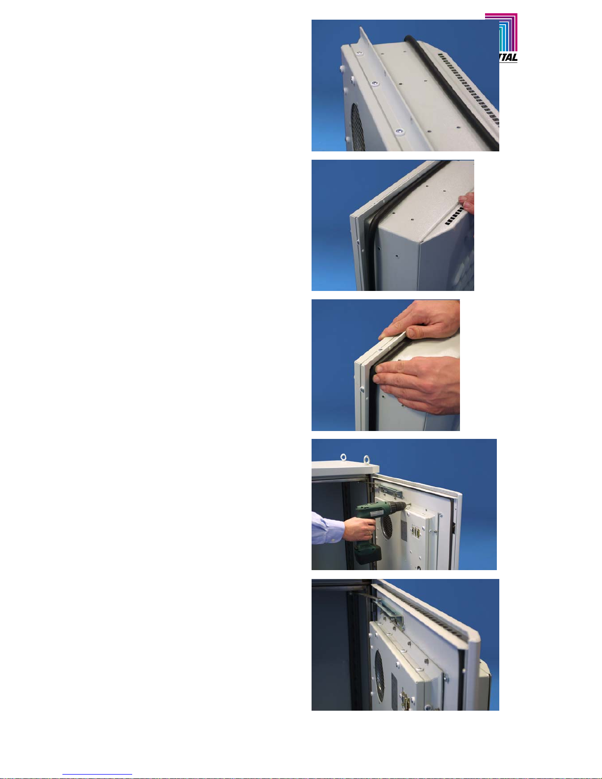
14. Ändern der Einbauposition 14. Changing the mounting position
Das Kühlgerät ist im Serienzustand in maximaler
Einbautiefe in das Gehäuse eingebaut. Die Montageposition kann auf Teileinbau oder Anbau geändert werden. Dazu sind folgende Arbeitsschritte
notwendig:
In the series fabrication type the cooling unit is
mounted with maximum depth in the enclosure.
The mounting position may be altered to partial internal mounting or external mounting. This requires
the following actions:
Lösen Sie die Schrauben des Befestigungsrahmens an der Innenseite der Tür.
Remove the screws from the mounting frame at the
inside of the door.
Entnehmen Sie deas Kühlgerät. Entfernen Sie vorsichtig die umlaufende Dichtung außen am Befestigungsrahmen.
Remove the cooling unit. Remove carefully the allround seal at the outside of the mounting frame.
Lösen Sie die Schrauben vom umlaufenden Befestigungsrahmen. Anschließend schieben Sie den
Befestigungsrahmen in die neue Position und verschrauben den Befestigungsrahmen. Das Kühlgerät bei diesen Arbeitsschritten nicht auf die Designhaube legen.
Loosen the screws at the all-round mounting frame.
Then move the mounting frame to the new position
and fix it with the screws. When carry ing out these
actions do not put down the cooling unit on the designer cover.
Page 20
_______________________________________________________________________________________
Montageanleitung CS 9776.500 / 9774.250 / 9774.450 11-2005 Technische Änderungen vorbehalten
Assembly instructions CS 9776.500 / 9774.250 / 9774.450 11-2005 Technical modifications reserved
Das runde Dichtgummi muss vor dem erneuten
Einsetzen in den Befestigungsrahmen mit Vaseline
bzw. säurefreiem Öl eingefettet werden. Verwenden
Sie dazu einen sauberen, fusselfreien Stofflappen
oder ein Zellstofftuch. Die Stoßstelle des
Dichtgummis wird unten angelegt.
Grease the all-round rubber seal with vaseline or
acid-free oil before re-attaching it. Use a clean, lintfree cloth or tissue for greasing. Position the joint in
the rubber at the bottom.
Das Dichtgummi wird in den Aufnahmerahmen
gedrückt. Durch das vorherige Einfetten verringert
sich die Reibung zwischen Dichtgummi und
Gehäuse. Zusätzlich wird die
Verformungseigenschaft der Runddichtschnur
erhöht: In montiertem Zustand führt dies zu einer
optimalen Abdichtung.
Press the rubber seal into the mounting frame.
Friction between the rubber seal and the enclosure
is reduced due to the previous greasing.
Additionally, the all-round rubber seal deforms mor e
easily. This leads to optimum sealing when the
device has been mounted.
Das Kühlgerät in den Türausschnitt einsetzen. Die
Befestigungsschrauben zunächst nur leicht
andrehen, danach alle Schrauben im „Kreuzgang“
anziehen.
Die Erdungsverbindung vom Kühlgerät ist mit der
gezahnten Kontaktscheibe herzustellen.
Mount the cooling unit in the cut-out of the door.
Attach screws initially without applying force, then
fix them properly "crosswise".
Use the toothed contact washer for earthing the
cooling unit.
Page 21

Montageanleitung CS 9776.500 / 9774.250 / 9774.450 11-2005 Technische Änderungen vorbehalten
Assembly instructions CS 9776.500 / 9774.250 / 9774.450 11-2005 Technical modifications reserved
Page 22

_______________________________________________________________________________________
Montageanleitung CS 9776.500 / 9774.250 / 9774.450 11-2005 Technische Änderungen vorbehalten
Assembly instructions CS 9776.500 / 9774.250 / 9774.450 11-2005 Technical modifications reserved
 Loading...