

Page 1
Blue e+ chiller
for cooling media
SK 3320200 SK 3334300 SK 3334400
Assembly and operating instructions
Page 2

Contents
EN
Contents
1 Notes on documentation .................. 4
1.1 General ........................................................ 4
1.2 CE conformity .............................................. 4
1.3 Storing the documents................................. 4
1.4 Symbols used in these operating instructions 4
1.5 Other applicable documents ........................ 4
2 Safety notes ..................................... 4
2.1 General ........................................................ 4
2.2 Risks in case of failure to observe the safety
instructions .................................................. 4
2.3 Safety instructions for assembly, inspection
and maintenance work ................................. 4
2.4 Unauthorised operation................................ 5
2.5 Health risks due to the refrigerant R134a and
the cooling medium ..................................... 5
2.6 First aid measures........................................ 5
2.7 Fire-fighting measures.................................. 5
2.8 Safety measures and equipment.................. 5
2.9 Potential hazards and how to avoid them..... 6
3 Device description ............................ 7
3.1 General ........................................................ 7
3.2 General functional description ...................... 8
3.3 Control......................................................... 9
3.4 Characteristic curves.................................... 9
3.4.1 Characteristic curves of pump ............................... 9
3.4.2 Performance diagrams ........................................ 10
3.5 Safety devices............................................ 10
3.6 Options...................................................... 10
3.6.1 Inverter pump ..................................................... 10
3.6.2 Reinforced pump ................................................ 10
3.6.3 Outdoor .............................................................. 10
3.6.4 Oil/emulsion ........................................................ 10
3.6.5 Free Cooling ....................................................... 10
3.6.6 Water-cooled condenser ..................................... 10
3.6.7 Tank heating ....................................................... 10
3.7 Proper use, foreseeable misuse ................. 10
3.8 Supply includes.......................................... 11
4 Transport ....................................... 11
4.1 Delivery ...................................................... 11
4.2 Unpacking ................................................. 11
4.3 Transport ................................................... 11
6 Commissioning .............................. 18
6.1 Cooling medium water-glycol mixture......... 18
6.1.1 General remarks ................................................. 18
6.1.2 Cooling medium requirements ............................ 18
6.1.3 Preparation and care .......................................... 19
6.1.4 Recommended "Cooling medium for chillers" ..... 19
6.2 Filling the cooling medium .......................... 20
6.3 Bleeding the cooling medium pump ........... 20
6.4 Commissioning procedure ......................... 21
6.5 Adjusting the bypass valve ......................... 21
7 Operation ....................................... 21
7.1 General ...................................................... 21
7.2 Layout of the display .................................. 22
7.2.1 Start screen ........................................................ 22
7.2.2 Changing a parameter value ............................... 22
7.2.3 Help function ...................................................... 23
7.3 Info menu................................................... 23
7.3.1 Temperature info ................................................. 23
7.3.2 Device info .......................................................... 23
7.3.3 Efficiency info ...................................................... 24
7.3.4 Hydraulic info ...................................................... 24
7.4 Configuration menu.................................... 24
7.4.1 Control parameters ............................................. 25
7.4.2 Remote ............................................................... 28
7.4.3 Network .............................................................. 28
7.4.4 Alarm relays ........................................................ 29
7.4.5 Language settings .............................................. 29
7.4.6 Self-test .............................................................. 29
7.5 System messages...................................... 30
7.5.1 Occurrence of a malfunction ............................... 30
7.5.2 Display in case of errors ...................................... 30
8 Inspection and maintenance .......... 30
8.1 Maintaining the refrigerant circuit................ 31
8.2 Monitoring the cooling medium .................. 31
8.3 Cleaning the condenser ............................. 32
8.4 Cleaning the filter mat (accessories)............ 32
8.5 Draining the cooling medium tank .............. 32
9 Troubleshooting ............................. 33
9.1 List of system messages ............................ 34
10 Decommissioning and disposal ...... 36
10.1 Decommissioning....................................... 36
10.2 Disposal ..................................................... 36
5 Assembly and connection .............. 13
5.1 Dimensions ................................................ 13
5.2 Installation site requirements ...................... 13
5.3 Installing the chiller..................................... 14
5.4 Making the hydraulic connection................ 14
5.5 Connecting the cooling circuit (optional) ..... 15
5.6 Making electrical connection ...................... 15
5.6.1 Installing the power supply .................................. 16
5.6.2 Connecting the alarm relay query device ............. 16
5.6.3 External activation ............................................... 16
5.6.4 Room temperature sensor (accessories) ............. 16
5.7 Installing the filter mats (accessories).......... 16
2 Rittal Chiller Blue e+
11 Accessories ................................... 37
11.1 Connection set for air/water heat
exchangers ................................................ 37
11.2 Flow regulator valve.................................... 37
11.3 Textile filter mats ........................................ 37
11.4 Metal filter (aluminium filter)......................... 38
11.5 Cooling medium for chillers (ready-mix) ...... 38
11.6 Levelling feet .............................................. 38
11.7 Twin castors............................................... 38
11.8 Cross member ........................................... 38
11.9 External temperature sensor....................... 39
Page 3

12 Appendix ....................................... 40
12.1 Block diagram............................................. 40
12.2 Spare parts................................................. 41
12.3 Technical specifications .............................. 42
12.4 Device drawings ......................................... 43
12.5 Operation of inverter pump ......................... 46
12.6 Declaration of Conformity............................ 47
Contents
EN
Rittal Chiller Blue e+ 3
Page 4
1 Notes on documentation
EN
1 Notes on documentation
1.1 General
These instructions are aimed at installers and operators
who are familiar with the installation and the operation of
the chiller. It is very important to read and follow these
assembly and operating instructions prior to commissioning. These are the original operating instructions.
1.2 CE conformity
Rittal GmbH & Co. KG confirms the conformity of the
chiller with the European Union's Machinery Directive
2006/42/EC and EMC Directive 2004/108/EC. A corresponding declaration of conformity has been issued and
enclosed with the unit.
1.3 Storing the documents
The assembly and operating instructions as well as all
other applicable documents are an integral part of the
product. They must be issued to everyone who works
with the chiller and must always be available and on
hand for operating and maintenance personnel.
1.4 Symbols used in these operating instructions
The following symbols are used in this documentation:
Danger!
A dangerous situation in which failure to
comply with the instructions will result in
death or severe injury.
1.5 Other applicable documents
Assembly and operating instructions exist as paper documents and/or digital data carriers for the unit types described here and are enclosed with the equipment.
We cannot accept any liability for damage associated
with failure to observe these instructions. Where applicable, the instructions for any accessories used also apply.
2 Safety notes
2.1 General
Please observe the following general safety notes when
operating and installing the chiller:
Assembly, installation and maintenance must only be
carried out by qualified personnel.
Children and persons with limited cognitive/coordina-
tive abilities must not operate, maintain or clean the
unit or be allowed to use it as a toy.
Only use original spare parts and accessories author-
ised by the manufacturer to ensure the protection and
safety of the chiller. The usage of other parts will render any liability void.
Do not make any changes to the chiller that have not
been agreed with and approved by the manufacturer.
It is also imperative that you observe the special safety
instructions for the individual activities in the individual
chapters.
2.2 Risks in case of failure to observe the safety instructions
In case of failure to observe the safety notes, people, the
environment and the chiller may be placed at risk. Failure
to comply with the safety notes makes all claims for
compensation void.
Warning!
A dangerous situation which may cause
death or serious injury if the instructions
are not followed.
Caution!
A dangerous situation which may lead to
(minor) injuries if the instructions are not
followed.
Note:
Important notices and indication of situations
which may result in material damage.
This symbol indicates an "action point" and shows that
you should perform an operation or procedure.
4 Rittal Chiller Blue e+
2.3 Safety instructions for assembly, inspection and maintenance work
– The installation, commissioning and servicing of the
chiller must be carried out in strict compliance with the
technical documentation for the chiller and in such a
way that no potentially hazardous situations are allowed to occur.
– Cleaning and maintenance work on the chiller must
only be performed with the unit shut down. For this
purpose, it is vital to ensure that the chiller is disconnected from the power supply and is secured against
switching back on. It is imperative that you observe the
procedure for shutting down the chiller described in
the assembly and operating instructions.
– All safety devices and protective equipment must be
reattached or put in a functional condition immediately
after the work is complete.
– Modifications or changes to the chiller are not allowed.
– Only appropriately qualified personnel as defined by
BGR500 chap. 2.35 / EN 378 are allowed to work on
the refrigerant circuit.
Page 5
– Do not install the chiller without protection outside of
covered areas, or in an explosive or aggressive environment.
– Do not install the chiller on an unstable surface or a
surface that is not designed for the weight of the chiller.
– Do not bypass any electrical safety devices to make it
possible to operate the chiller.
2.4 Unauthorised operation
The safety of the chiller supplied is only ensured if it is
used properly (see section3.7 "Proper use, foreseeable
misuse"). Under no circumstances should the limit values specified in the technical data be exceeded.
The chiller is not allowed to be used for the direct cooling
of liquids that are used for foodstuffs (e.g. drinking water).
Any existing contact hazard protection for moving parts
must not be removed from chillers while operational.
Hazards due to electrical power, do not remove any
switch box cover!
2 Safety notes
EN
Explosion hazard!
The use of the chiller for cooling inflam-
mable or pyrophoric substances is prohibited.
2.5 Health risks due to the refrigerant R134a and the cooling medium
The refrigerant changes status during operation and becomes pressurised. The R134a safety data sheet must
be observed.
The cooling medium (additive) is a liquid. We suggest:
"Cooling medium for chillers" (see section6.1 "Cooling
medium water-glycol mixture"). The safety data sheet
"Cooling medium for chillers" must be observed.
2.6 First aid measures
Please refer to safety data sheets R134a and "Cooling
medium for chillers".
Note:
Safety data sheets are available for down-
loading at www.rittal.com.
2.7 Fire-fighting measures
Suitable extinguishing agent
All known extinguishing agents can be used.
2.8 Safety measures and equipment
Ensure adequate ventilation.
Hand protection: Safety gloves.
Eye protection: Safety goggles.
Body protection: Wear safety shoes when handling
pressurised gas bottles.
Rittal Chiller Blue e+ 5
Page 6

EN
2 Safety notes
2.9 Potential hazards and how to avoid them
The following table provides an overview of other potential sources of danger and how to avoid them.
Location Hazard Cause Precautionary measures
Device interior Severe personal
injury or damage to
property
Device interior Personal injury or
damage to property
Device interior Inhalation of toxic
gases/materials
Device interior Risk for the prod-
uct
Device interior: Microchannel condenser
Device interior:
Hot or cold parts
Minor cuts Contact while cleaning the
Burns / frostbite Contact with parts with a
Hazard due to electrical
equipment of the chiller
Electrical hazard while
working on the chiller
Soldering work inside the
chiller may release toxic
gases due to the installed
cooling circuit.
Liquid level after transport
not in upright position
condenser (see section8.3 "Cleaning the
condenser")
high or low surface temperature.
Recurrent testing of electrical equipment
(Germany BGV A3)
The power to the chiller must be disconnected via the main switch.
Maintenance may only be carried out by specialist personnel. Before carrying out soldering work on the cooling circuit or in its
immediate vicinity, the refrigerant should be
drained from the chiller.
Only transport the chiller upright. Should the
chiller be tilted during transportation, please
wait some minutes before switching on
again.
Wear safety gloves.
The chiller may only be opened by trained,
qualified personnel.
Device interior:
Cooling medium circuit
Device exterior Severe personal
Device exterior Personal injury or
Device exterior Cuts Contact with fan wheel Do not remove the protective cover around
Device exterior:
Area around the chiller
Device exterior:
Chiller with wheels
Tab. 1: Hazards and precautionary measures
Fungus and algae
formation
injury or damage to
property
damage to property
Major burns Fire caused by short-cir-
Personal injury or
damage to property
Use of pure water as a
cooling medium or refrigerant.
The floor on which the
chiller is installed is unstable and unable to support
its weight. The chiller tips
over or the floor gives way.
Hazards when transporting or assembling the chiller
cuiting or overheating of
the electricity supply line to
the chiller
The chiller starts to move
due to unevenness of the
floor surface.
Use a water-glycol mixture as your cooling
medium. Rittal recommends the use of
"Cooling medium for chillers" (ready-mix).
The weight of the chiller can be found in section12.3 "Technical specifications". Additionally, please allow for the weight of the
liquid in the tank (the capacity of the tank can
likewise be found in section 12.3 "Technical
specifications") and make sure that the floor
is suitable for installation purposes.
Secure the chiller against any risk of tilting
(eyebolts) when transporting or assembling.
the fan wheel.
Ensure that the cable cross-section and electricity supply line comply with the valid regulations.
If the recooling system is equipped with
wheels (option), they must be locked with
brakes while operational.
6 Rittal Chiller Blue e+
Page 7
3 Device description
5
4
2
3
1
16
15
14
13
11
12
10
9
6
7
8
Note:
Specialist personnel are individuals who, by
virtue of their training, education, experience
and knowledge of the relevant provisions,
regulations and measures for accident prevention and relating to the operating conditions, have been authorised by the owner or
responsible individual to ensure the safety of
the system, carry out all essential tasks, and
are therefore in a position to identify and avert
all potential threats.
3 Device description
3.1 General
Chillers are used for the central and economical cooling
and supply of a cooling medium (water + glycol, see section6.1 "Cooling medium water-glycol mixture") in the
event of physical separation between the place where
cooling is required and the refrigeration. The cooling medium is supplied using a pipe system.
EN
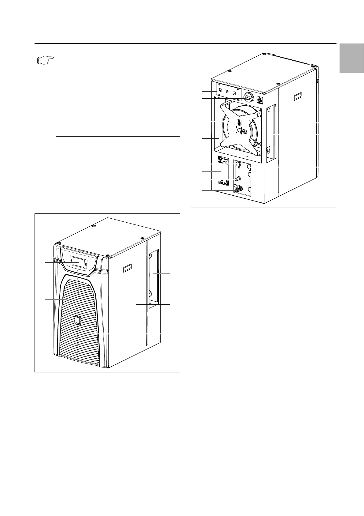
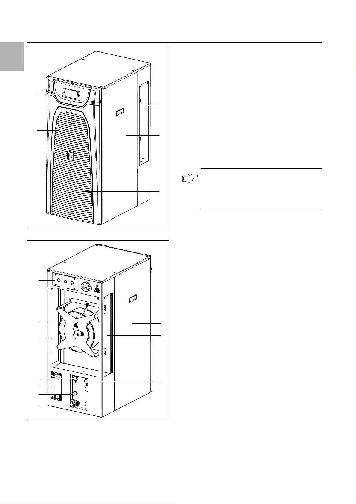
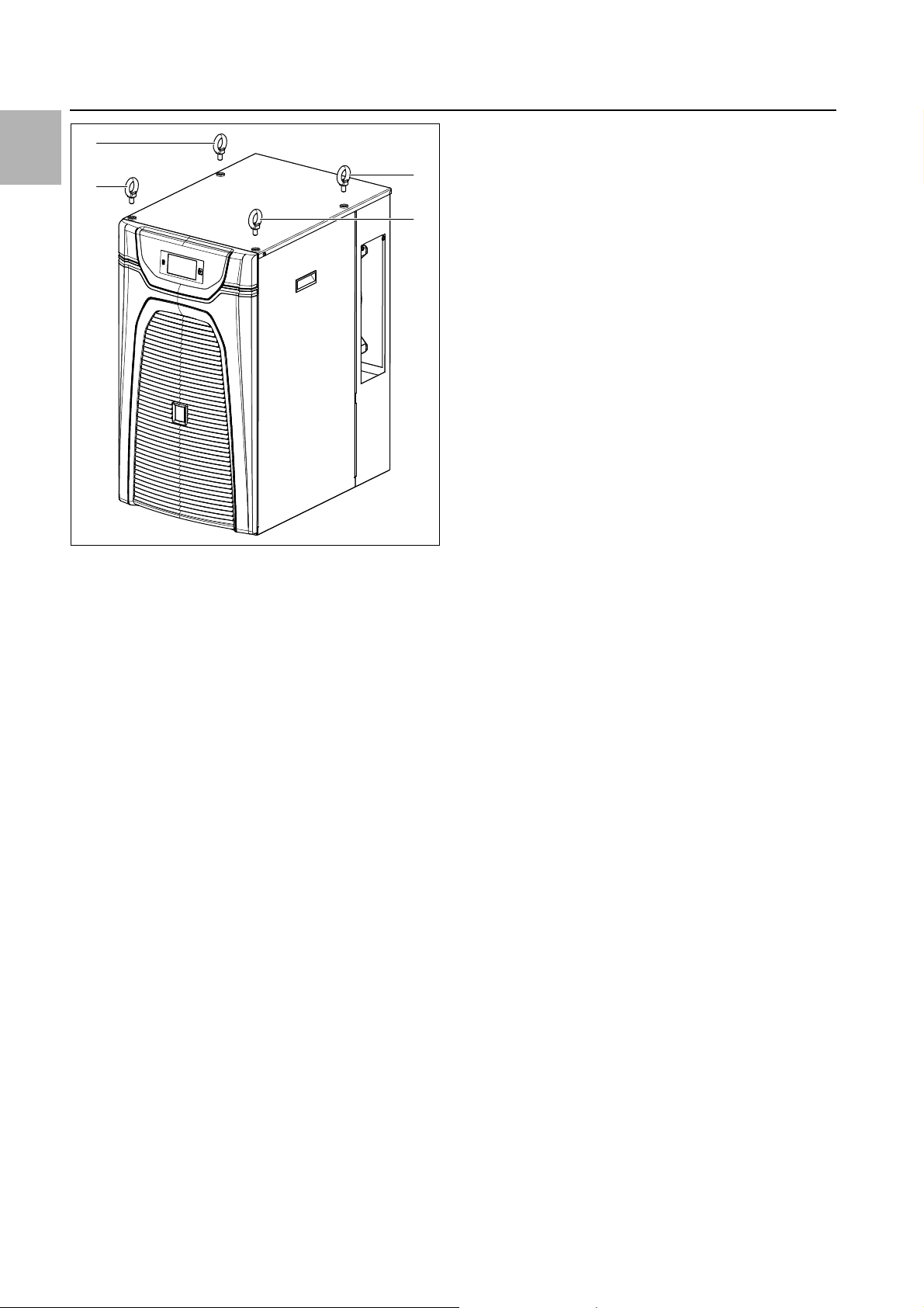
Fig. 2: View from rear (3320200 and 3334300)
Key fig. 1 and fig. 2
1 Side air outlet, right
2 Side cover, right
3 Filler nozzle for cooling medium (behind louvred grilles)
4 Louvred grille for air inlet
5Display
6 Side cover, left
7 Side air outlet, left
8 Cooling medium connection, inlet
9 Tank drain nozzle (stop valve)
10 Adjustable overflow valve (bypass)
11 Rating plate
12 Cooling medium connection, return
13 Air outlet, rear
14 Radial fan
15 Master switch
16 Electrical interfaces
Fig. 1: View from front (3320200 and 3334300)
Rittal Chiller Blue e+ 7
Page 8
EN
5
4
2
3
1
16
15
14
13
11
12
10
9
6
7
8
3 Device description
Key fig. 3 and fig. 4
1 Side air outlet, right
2 Side cover, right
3 Filler nozzle for cooling medium (behind louvred grilles)
4 Louvred grille for air inlet
5Display
6 Side cover, left
7 Side air outlet, left
8 Cooling medium connection, inlet
9 Tank drain nozzle (stop valve)
10 Adjustable overflow valve (bypass)
11 Rating plate
12 Cooling medium connection, return
13 Air outlet, rear
14 Radial fan
15 Master switch
16 Electrical interfaces
Note:
The motor circuit-breaker of the cooling me-
dium pump is accessed by opening the roof
plate. See also Q1 in section12.1 "Block diagram".
The chiller is equipped with an open reservoir for the
cooling medium.
Fig. 3: View from front (3334400)
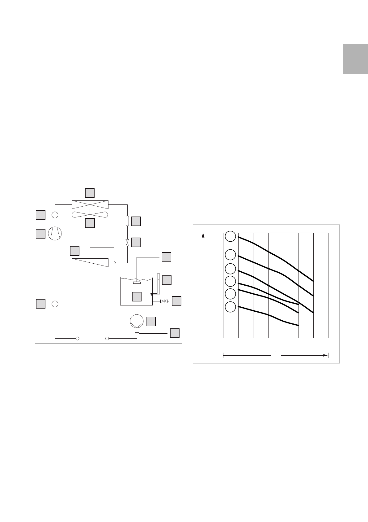
3.2 General functional description
The chiller comprises four main components (see fig. 5):
– Evaporator coil (item 12),
– refrigerant compressor (item 13),
– condenser (item 1) with fan (item 2),
– control or expansion valve (item 4),
which are connected together by pipes. A pressure
switch (item 14) limits the maximum pressure in the refrigerant circuit. The refrigerant R134a (CH2FCF3) is
chlorine-free. Its Ozone Depletion Potential (ODP) is 0.
A filter drier (item 3) which is integrated into the hermetically sealed refrigerant circuit provides effective protection against moisture, acid, dirt particles, and foreign
bodies. A temperature control with temperature probe
(item 6) ensures that the cooling medium is maintained
at a preset setpoint temperature.
In the evaporator coil (item 12), the liquid refrigerant is
converted to a gaseous state. The heat necessary for
this purpose is taken from the cooling medium in the
Fig. 4: View from rear (3334400)
8 Rittal Chiller Blue e+
plate heat exchanger, which has the effect of cooling the
cooling medium. The refrigerant is compressed in the
compressor (item 13). As a result the refrigerant has a
higher temperature than the ambient air. The DC inverter
technology enables load-specific speed control of the
compressor motor, so that only the power actually
needed is supplied.
This heat is dissipated to the ambient air over the surface
of the condenser (item 1), resulting in the refrigerant
liquefying again. A water-cooled condenser may optionally be used (see section3.6.6 "Water-cooled condenser").
Page 9
3 Device description
1
12
2
13
14
11
9
7
8
10
6
3
4
P
S
5
F
D
E
B
C
A
50 101520253035
6
5
4
3
2
1
P
Q
The refrigerant is injected into the evaporator (item 12)
via an electronic expansion valve (item 4), causing it to
expand and as a consequence is able to absorb the heat
from the cooling medium (water or water-glycol mixture).
The cooling medium is pumped to the equipment in an
additional circuit via the cooling medium tank (item 10)
and the cooling medium pump (item 9). The flow sensor
(item 11) ensures that the evaporator (item 12) is protected against freezing and running dry if the flow rate is
too low. The level switch (item 5) emits a warning if the
level in the cooling medium tank is too low. The inlet
temperature of the cooling medium (water or water-glycol mixture) is regulated using the temperature sensor
(item 6) on the water outlet. Optionally, an inverter pump
may also be used, so that the cooling medium pump is
also speed-controlled.
A layout drawing of the refrigerant circuit may be found
in fig. 5.
3.3 Control
The chillers are fitted with a controller for setting the
functions of the chiller.
Operation using this controller is described in section7
"Operation".
Within the compressor speed range from 25...100%, the
compressor is in continuous control mode. During continuous control mode, the control accuracy of the water
inlet temperature is ±0.5 K or better. At smaller loads requiring a speed of less than 25%, the compressor
switches to cycle mode, and the control accuracy of the
water inlet temperature is adjusted to ±2 K (refer to the
performance curves on the Rittal website).
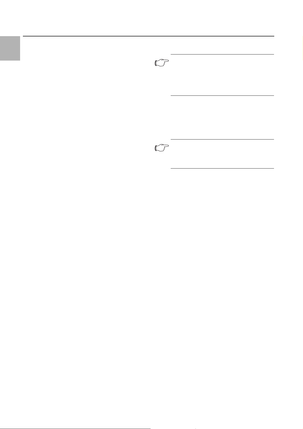
3.4 Characteristic curves
3.4.1 Characteristic curves of pump
Characteristic curves measured under the following
conditions:
– Ambient temperature (T
– Medium temperature (T
– Cooling medium "water"
) = 32°C
a
) = 18°C
w
EN
Fig. 5: Schematic diagram of refrigerant circuit
Key
1 Condenser, air-cooled
2 Condenser fan (radial fan)
3 Filter dryer
4Expansion valve
5 Fill level monitoring
6 Temperature sensor
7 Fill nozzle
8 Tank drain nozzle
9 Cooling medium pump
10 Cooling medium tank
11 Flow sensor
12 Evaporator (plate heat exchanger)
13 Compressor
14 Pressure-operated switch
Rittal Chiller Blue e+ 9
Fig. 6: Characteristic curves
Key fig. 6
A 3320200 standard pump 50 Hz
B 3320200 standard pump 60 Hz
C 3320200 reinforced pump 50 Hz (option) or
3334300 and 3334400 standard pump 50 Hz
D 3320200 reinforced pump 60 Hz (option) or
3334300 and 3334400 standard pump 60 Hz
E 3334300 and 3334400 reinforced pump 50 Hz (option)
F 3334300 and 3334400 reinforced pump 60 Hz (option)
P External static pressure [bar]
Q Delivery flow [l/min]
The flow speed of the circulating medium is monitored
with a flow sensor. The sensor has a preset alarm
threshold and a variable warning threshold that can be
Page 10
3 Device description
EN
set by the operator. When the warning threshold is
reached, a message is produced, and when the alarm
threshold is reached, a fault is generated.
If the flow rate of the circulating medium during operation drops below 4 l/min, the integrated flow sensor will
trip.
3.4.2 Performance diagrams
The performance diagrams can be found on the Rittal
website.
3.5 Safety devices
– In the cooling circuit, the chiller has a type-tested pres-
sure monitor (to EN 12263) which switches off the
chiller if the maximum admissible pressure is exceeded. Once the pressure drops back below the admissible pressure, the unit will automatically resume operation.
– Temperature monitoring prevents the evaporator coil
from icing over. The compressor gradually reduces the
output within the range 100...25%. If the risk of icing
persists for more than 2 minutes, the compressor will
switch off completely. At higher temperatures, the unit
automatically returns to control mode.
– The compressor motor and the fan motor are moni-
tored and protected by the inverter to prevent overloading.
– The cooling medium pump has a motor circuit-breaker
to prevent overcurrent and short-circuits.
– To ensure smooth-running and reliable operation (for
example after reaching the setpoint temperature or after a fault), the compressor automatically switches
back on after a delay.
– The chiller has floating contacts on terminals 8 to 10 of
the signal connector (X2), via which system messages
from the device may be polled, e.g. using a PLC (2 x
normally closed or normally open contacts).
3.6 Options
3.6.1 Inverter pump
The cooling medium pump can be designed as an inverter pump. In such cases, the pump is speed-controlled depending on the actual cooling medium demand
(see section12.5 "Operation of inverter pump").
3.6.2 Reinforced pump
For applications requiring a higher cooling medium
throughput or pressure, the cooling medium pump can
be designed in a higher output category.
3.6.3 Outdoor
The "Outdoor" option allows the chiller to be sited outside. To this end, the chiller is coated with a special
spray-finish. Outdoor siting means that the air at the system installation site is not additionally subject to waste
process heat.
For outdoor siting, a rain canopy should be provided by
the customer to protect the chiller from downpours.
Note:
With outdoor siting of the chiller, it is impor-
tant to ensure that a suitable cooling medium
is used (see section6.2 "Filling the cooling
medium"). This is the only scenario in which
operation to -20°C is admissible.
3.6.4 Oil/emulsion
Oil or an emulsion may also be used as a cooling medium, instead of the water/glycol mixture used as standard. In such cases, the components in the cooling circuit
are adapted accordingly, and the thermal capacity of the
cooling medium must be stored in the control system.
Note:
For the purpose of these instructions, we
have assumed that a water/glycol mixture is
used as the cooling medium.
3.6.5 Free Cooling
The "Free Cooling" option allows you to cool without the
refrigerant circuit in so-called hybrid mode. If this type of
cooling is preselected in the control system, with outdoor siting of the chiller, the system first attempts to use
only the (cold) ambient air to cool the cooling medium. If
this is no longer possible because the external temperatures are too high, it automatically activates the conventional cooling circuit to supply the required cooling medium temperature.
3.6.6 Water-cooled condenser
The condenser may be water-cooled. In such cases, a
separate cooling circuit must be connected to the condenser.
3.6.7 Tank heating
A tank heater may be installed to pre-heat the cooling
medium or for frost protection. A setting is made in the
control system to determine when the tank heater is
switched on and off.
3.7 Proper use, foreseeable misuse
The chiller is only used for cooling water-glycol mixtures.
Any other use is deemed improper. One exception to
this is operation with the "oil/emulsion" option (see section3.6.4 "Oil/emulsion").
When using other fluids, please refer to the technical
specifications in the appendix, or contact the manufacturer. Under no circumstances should the specified limits in the technical data be exceeded.
The chiller is state of the art and built according to recognised safety regulations. Nevertheless, improper use
can pose a threat to the life and limb of the user or third
10 Rittal Chiller Blue e+
Page 11
4 Transport
parties, or result in possible damage to the system and
other property.
Consequently, the chiller must only be used properly
and in a technically sound condition! Any malfunctions
which impair safety should be rectified immediately.
Proper use also includes the observance of the documentation provided and compliance with the inspection
and maintenance conditions, and strictly professional
use as defined in DIN EN 61000-3-2.
Rittal GmbH & Co. KG is not liable for any damage which
may result from failure to comply with the documentation provided. The same applies to failure to comply with
the valid documentation for any accessories used.
Inappropriate use may be dangerous. Examples of inappropriate include:
– Use of the chiller for cooling flammable or combustible
substances.
– The chiller must never be used for the direct cooling of
liquids used in the food industry (e.g. drinking water).
– Use of impermissible tools.
– Improper operation.
– Improper rectification of malfunctions.
– Use of accessories not approved by Rittal GmbH &
Co. KG.
3.8 Supply includes
Qty. Description
1Chiller
1 Shipping bag with
1 – Assembly and operating instructions
1 – Connector
1 – Signal connector
4 – Eyebolt and plastic washer
2 – M25 screw connection
1 – M20 screw connection
Tab. 2: Scope of supply
4.2 Unpacking
Only transport the chiller in its original packaging ma-
terial before commissioning for the first time.
Remove the packaging materials from the chiller.
Note:
After unpacking, the packaging materials
must be disposed of in an environmentally
friendly way.
Check the chiller for any damage that may have oc-
curred during transport.
Note:
Damage and other faults, e.g. incomplete de-
livery, should be reported immediately, in
writing, to the shipping company and to Rittal
GmbH & Co. KG.
Check the supply contents for completeness (see sec-
tion 3.8 "Supply includes").
4.3 Transport
If the chiller is stored or transported at temperatures below freezing, return to room temperature before commissioning. This instruction also applies to the external
condenser circuit for a water-cooled condenser (option).
When transporting the chiller, please make allowance
for the weight specified in section12.3 "Technical
specifications".
Use lifting gear with a suitable load capacity.
If it is necessary to move the chiller in the factory, you
must disconnect all connections on the chiller.
Before transporting, empty the water circuit and tank
(see section8 "Inspection and maintenance").
Prevent excessive vibration.
Only transport the chiller upright.
Only transport the chiller on the pallet supplied with the
chiller or with the eyebolt provided (fig. 7, item 1).
Serrated washers for earthing are fitted to the eyebolts
in the mounted state. After transportation, the eyebolts
are exchanged for the pan-head screws provided. Plastic washers are included in the bag of accessories to
protect the paint.
Protect the chiller from unintentional movement (e.g.
when being transported by vehicle).
EN
4Transport
4.1 Delivery
The chiller is supplied in a packaging unit in a fully assembled state.
Check the packaging carefully for signs of damage.
Traces of oil on damaged packaging indicate a loss of
refrigerant and/or a leak in the chiller. Any packaging
damage may be the cause of a subsequent functional
failure.
Rittal Chiller Blue e+ 11
Page 12
EN
1
1
1
1
4 Transport
Fig. 7: Eyebolt for transportation (3320200)
12 Rittal Chiller Blue e+
Page 13
5 Assembly and connection
710 mm450 mm
1020 mm
450 mm
710 mm
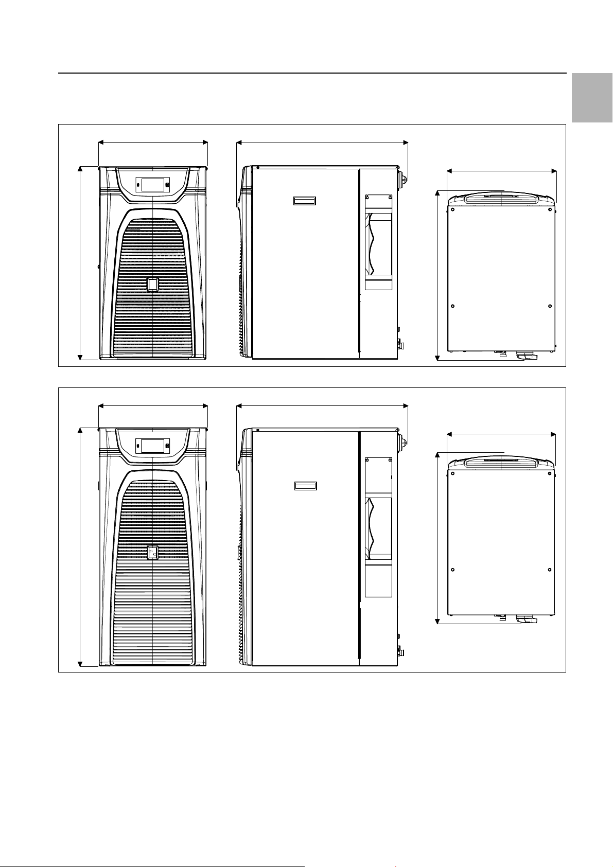
5.1 Dimensions
5 Assembly and connection
EN
450 mm
820 mm
Fig. 8: Dimensions 3320200 and 3334300
710 mm
450 mm
710 mm
Fig. 9: Dimensions 3334400
5.2 Installation site requirements
– The chiller must be adequately protected from external
weather conditions.
– If the ambient air contains a high concentration of dust
or oily substances, the chiller should be fitted with a
metal filter (see section11.4 "Metal filter (aluminium filter)").
Rittal Chiller Blue e+ 13
– The supporting surface should be flat and sufficiently
robust to hold the weight (see section12.3 "Technical
specifications") during operation.
– If the chiller is sited outdoors, the "Outdoor" option
must be used (see section3.6.3 "Outdoor").
– The ambient temperature must lie within the limit val-
ues indicated in the technical specifications (see sec-
tion12.3 "Technical specifications").
Page 14
5 Assembly and connection
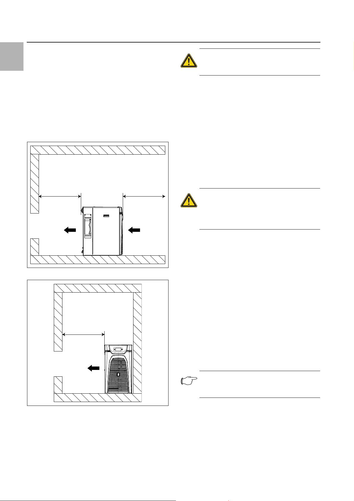
300 mm
EN
– In order to prevent performance losses caused by
pressure drops in the pipework, the chiller should be
sited as close as possible to the equipment.
– At least one of the openings (left or right) must be freely
accessible to enable the unhindered expulsion of hot
air (see fig. 11). To allow connection of the supply lines
and facilitate maintenance and repair work, the minimum distances shown under fig. 10 should be adhered to.
– In order to avoid an "air short-circuit" (mixing of air in-
take and waste air) and ensure full cooling performance, the minimum distances shown under fig. 10
should likewise be adhered to.
300 mm 800 mm
Caution!
The connection of an air intake / waste
air duct is inadmissible.
To prevent performance losses, do not install the chill-
er near any form of heating.
Outdoor siting
Chillers must be installed such that they cannot become
damaged by internal traffic and transport operations.
5.3 Installing the chiller
Install the chiller on an even, firm surface. The maxi-
mum permissible deviation from the vertical is 2°.
Avoid the production of noise due to vibration (vibra-
tion dampers, sheets of foam rubber).
5.4 Making the hydraulic connection
Caution!
Risk of damage to the cooling medium
pump due to soiling in the cooling medium circuit! Flush the cooling medium circuit prior to connecting the chiller.
Fig. 10: Minimum distances, front/rear
Fig. 11: Minimum distances, sides
Ensure the room is adequately ventilated by installing
the chiller such that the warm exhaust air does not
heat the room excessively.
In case of installation in a "small" room, it is imperative
that you provide forced ventilation, as otherwise the
heat dissipated will build up.
The cooling medium outlet (fig. 2 or fig. 4, item 8) on the
chiller must be connected to the cooling medium inlet on
the equipment to be cooled. At the same time, the cooling medium inlet (fig. 2 or fig. 4, item 12) on the chiller
must be connected to the cooling medium outlet on the
equipment to be cooled. Please observe the following:
– To avoid condensation, always connect the equip-
ment using insulated pipelines and/or hoses.
– The nominal width of the piping must correspond at
least to the nominal width of the media connections on
the chiller.
– The cooling medium infeed to the chiller must be pres-
sureless, because the tank used in the system is open
to the atmosphere.
– Never connect the chiller to the drinking water supply.
– The pipework must be approved for the maximum
pressure expected (see section12.3 "Technical spec-
ifications").
Note:
The use of steel pipes or galvanised steel
pipes is inadmissible.
Prior to commissioning, it is imperative that the cooling
medium pump is filled with cooling medium and bled
(see section6.3 "Bleeding the cooling medium pump").
14 Rittal Chiller Blue e+
Page 15
5 Assembly and connection
Caution!
An insufficient flow rate will trigger the
safety devices in the chiller. Pay attention to the minimum pressure required
and the minimum flow rate required (see
section12.3 "Technical specifications").
If the cooler on the equipment to be cooled is higher
than the chiller, we recommend installing a non-return
valve in the feed as well as a solenoid valve in the cooling
medium circuit return to prevent the tank from overflowing.
A bypass valve should be connected between the inlet
and return to protect the cooling medium pump. This
opens automatically, for example, if the equipment cycle
is shut off. Section6.5 "Adjusting the bypass valve" describes how to set the bypass valve.
5.5 Connecting the cooling circuit (optional)
If the chiller is equipped with the "water-cooled condenser" option (see section3.6.6 "Water-cooled condenser"), a cooling water supply must additionally be
connected to the condenser.
Additionally make the cooling water connections to
the condenser.
5.6 Making electrical connection
When carrying out the electrical installation, observe all
applicable national and regional regulations as well as
the regulations from the responsible utility company.
– Electrical installation must only be carried out by a
qualified electrician who is responsible for compliance
with the existing standards and regulations.
– All cables routed into the wiring compartment have to
be insulated for the maximum voltage of the power
supply.
Note:
The mains supply must be of a shielded de-
sign to guarantee the level of EMC protection.
– The cable shielding can contact the earth
terminal to the enclosure inside the connection box (fig.13, item 1).
– To ensure the proper functioning of internal presso-
stats in the event of a malfunction, a slow (time delay)
line fuse of no less than 15 A is required.
– Low-noise potential equalisation must be guaranteed
with the mains connection. As a general principal, the
chiller must be integrated into the building's potential
equalisation system.
– The conductor cross-sections of the power cable
must be selected according the rated current (see rating plate).
– The connection must be made with the field rotating
clockwise. The direction of rotation of the field can be
measured at the connection terminals L1, L2 and L3.
Connect with a clockwise rotating field to ensure that
the cooling medium pump motor rotates in the correct
direction.
Overvoltage protection and supply line load
– The chiller does not have its own overvoltage protec-
tion. Measures must be taken by the operator at the
supply end to ensure effective lightning and overvoltage protection.
– The mains voltage must not deviate by more than the
tolerance specified in section12.3 "Technical specifications".
– The chiller and its power electronics are designed in
accordance with overvoltage category III. If the combined output of the frequency converters, power converters or transformers in the network where the device is being operated is >70 kVA, the customer must
connect a Class II surge voltage protector in the mains
supply line upstream of the chiller. The surge voltage
protector must be designed to EN 61800 -1. The following values may be assumed as starting-points for
the design:
Transformers,
power electronics
70 kVA…100kVA 40J
100 kVA…200kVA 80J
200 kVA…400kVA 160J
400 kVA…800kVA 320J
Tab. 3: Design of the surge voltage protector
Assumed discharge
energy
EN
Connection data
– The connected voltage and frequency must corre-
spond to the ranges stated on the rating plate. The
units support multiple voltages.
– The chiller must be connected to the mains via an all-
pole isolating device.
– If a motor circuit-breaker or circuit-breaker is used, it
should be selected in accordance with EN 60898-1
(tripping characteristic type D).
Rittal Chiller Blue e+ 15
Interfaces
If you would like system messages from the chiller to be
evaluated via the alarm relay, you should also connect a
suitable low-voltage cable to the X2 signal connector
(see section5.6.2 "Connecting the alarm relay query device").
If you require remote activation of the chiller, this can
likewise be achieved via the X2 signal connector (see
section5.6.3 "External activation") and appropriate programming (see section7.4.2 "Remote").
Page 16

EN
3
4
1
2
5 Assembly and connection
5.6.1 Installing the power supply
Remove the mains connector from the dispatch bag
and connect to the mains as shown on the connection
diagram (fig. 12).
Fig. 12: Circuit diagram
Strain relief
Please provide suitable strain relief for the connection
cable.
When connecting the cooling unit in accordance with
NFPA 70 (NEC):
Use the cover for the connection unit and a conduit fit-
ting.
Use copper conductors only to connect the supply ca-
ble to the mains connector.
5.6.2 Connecting the alarm relay query device
System messages from the cooling unit may be output
to an external signal source via two floating relay outputs.
AC
cos φ = 1
I max. = 2 A
U max. = 250 V
Tab. 4: Contact data
5.6.3 External activation
The chiller has been prepared for control via an external
signal.
Connect a floating contact to terminals 5 and 6 of the
X2 signal connector.
Configure how you want the external enabling signal to
be evaluated (see section7.4.2 "Remote").
This function is deactivated by default, i.e. the chiller is
permanently in operational mode. With the function activated and the contact open, the cooling function and,
where applicable, the cooling medium pump are
switched off.
5.6.4 Room temperature sensor (accessories)
The chiller allows for room-temperature-based control.
This requires a room temperature sensor (see section11.9 "External temperature sensor"), available as an
optional accessory.
Connect the room temperature sensor to terminals 1
and 2 of the X2 signal connector.
Configure the chiller control mode so that the temper-
ature is regulated by the sensor measurement (see
section7.4.1 "Control parameters").
Fig. 13: Connection box
Key
1Earth tag
2 Connector connection (X1)
3 IoT interface connection 3124300 (X4)
4 Connection for signal connector (X2)
Note:
The factory setting of the relay outputs in their
de-energised state is NO (Normally Open).
Connect a suitable connection cable to the connec-
tion terminals 9 (Alarm K1) and/or 10 (Alarm K2) of the
signal connector (X2).
Configure the alarm relays you wish to use to output
error messages (see section 7.4.4 "Alarm relays").
5.7 Installing the filter mats (accessories)
For dry, coarse dust and lint in the ambient air, we recommend installing an additional PU foam filter mat (available as an accessory) in the chiller. Depending on the incidence of dust, you will need to replace the filter mat
from time to time (see section5.7 "Installing the filter
mats (accessories)").
For ambient air containing oil, we recommend the use of
metal filters (see section11.4 "Metal filter (aluminium filter)"). These may be cleaned with suitable detergents
and reused (see section8.4 "Cleaning the filter mat (accessories)").
Types 3320200 and 3334300
At the front of the chiller, pull the louvred grille (fig. 14,
item 3) away from the mounting clips (fig. 14, item 2),
and place or lay it down somewhere safe.
16 Rittal Chiller Blue e+
Page 17
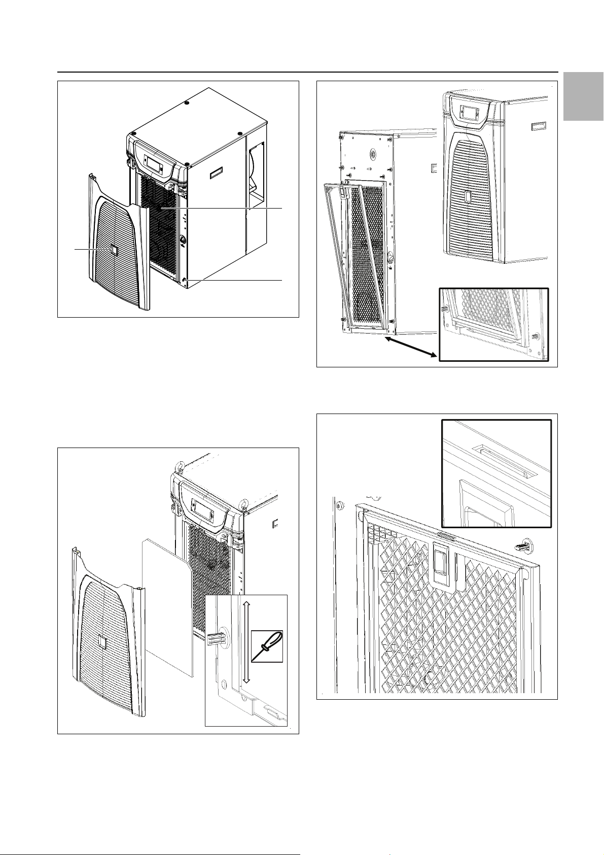
Fig. 14: Pull off the louvred grille 3320200 and 3334300
3
2
1
Key
1 Filter holder
2 Mounting clips (4x)
3 Louvred grille
Textile filter mat
Re-insert the filter mat into the frame at the front.
If necessary, use a tool, such as a screwdriver, to
press the filter into the U-section of the frame.
5 Assembly and connection
EN
Fig. 16: Insert the metal filter 3320200 and 3334300
Press in the filter at the top until the lug locks home
into the frame.
Fig. 17: Press in the metal filter 3320200 and 3334300
Textile filter mat and metal filter
Fig. 15: Insert the textile filter mat 3320200 and 3334300
Metal filter
Position the metal filter on the frame at the bottom.
Rittal Chiller Blue e+ 17
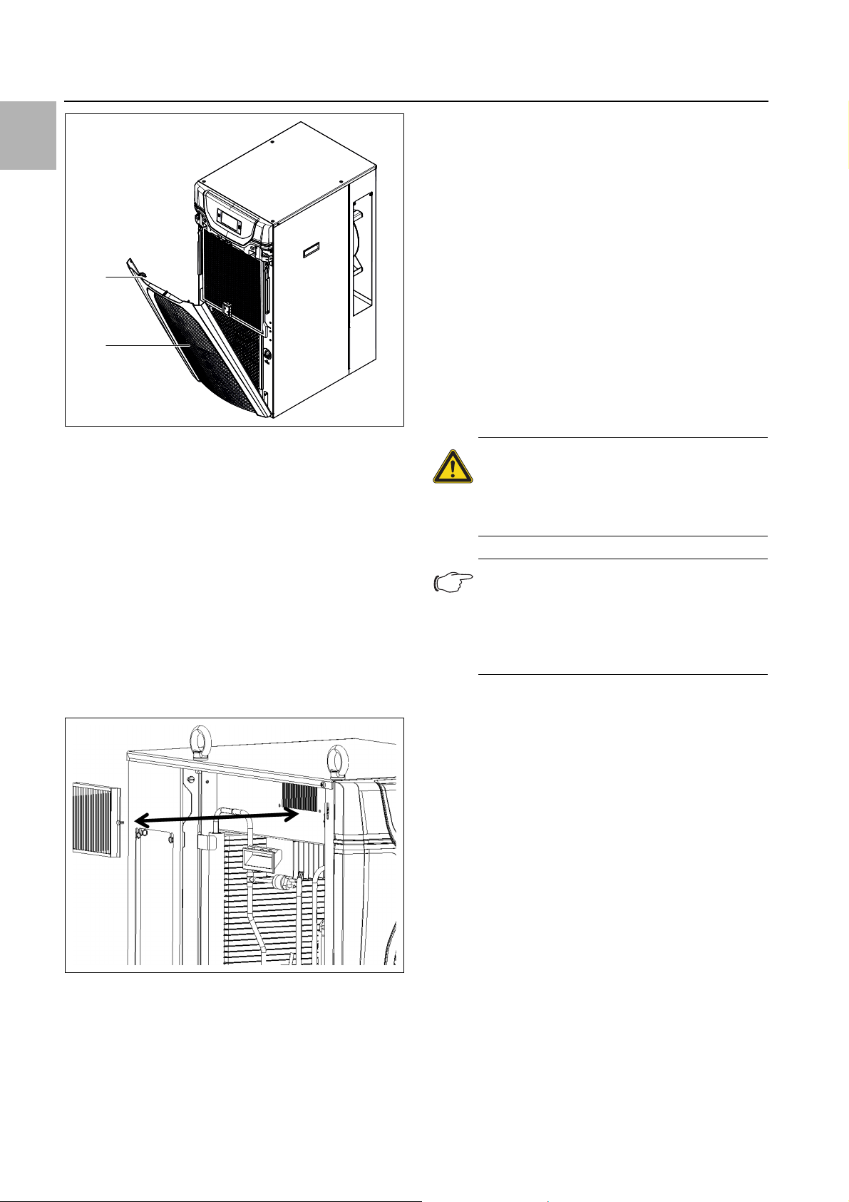
Press the louvred grilles back onto the mounting clips.
Type 3334400
Open the louvred grille below the infill panel by flipping
forwards (fig. 18, item 1).
Page 18
EN
1
2
6 Commissioning
Fig. 18: Flip open the louvred grille 3334400
Key
1 Louvred grille
2 Filter holder
Push the textile filter mat or metal filter into the back of
the filter holder on the rear of the louvred grille.
Push the louvred grille backwards so that it locks
home on the chiller.
Install the pleated filter for the inverter housing
Remove the left-hand side panel, and place or lay it
down somewhere safe.
If a pleated filter is already installed, loosen the split riv-
ets and remove the pleated filter from the inverter
housing.
6 Commissioning
The chiller has a master switch allowing it to be switched
off for maintenance work.
In day-to-day operation, it should be switched on and off
by the higher-level controller.
6.1 Cooling medium water-glycol mixture
As standard, the chiller is not suitable for operation below the specified minimum temperature (see section12.3 "Technical specifications").
Generally speaking, a water-glycol mixture with a maximum glycol proportion of between 20 and 34% by volume should be used as the cooling medium. We recommend our ready-mixed "Cooling medium for chillers"
(see section6.1.4 "Recommended "Cooling medium for
chillers""). Other water-glycol mixtures may be possible
in individual cases, but only in consultation with the manufacturer.
Caution!
Other additives may damage the pipes
and the seal on the cooling medium
pump, and are therefore only admissible
by arrangement with Rittal.
Note:
With the chiller sited outdoors ("Outdoor" option), it is important to adjust the glycol proportion accordingly. This can be ensured by
using the premixed outdoor medium "Cooling medium for chillers".
6.1.1 General remarks
When cooling the water-glycol mixture in an open circuit,
always remember that algae, deposits and corrosion
can damage the chiller. Residues will always impair the
performance of the chiller. Without water treatment it is
only seldom possible to achieve satisfactory conditions.
By means of regular monitoring of the quality of the cooling medium and cooling medium treatment, you must
ensure that deposits and corrosion are avoided, even
under extreme conditions.
6.1.2 Cooling medium requirements
The cooling medium must not cause any limescale deposits or loose debris. In other words, it should have a
low level of hardness, particularly a low level of calcium
hardness. In particular, the level of calcium hardness
should not be too high when using the equipment for re-
Fig. 19: Insert the pleated filter.
Insert a new pleated filter and secure with the split
rivet.
Close the side panel again.
circulated cooling. On the other hand, the cooling medium should not be so soft that it attacks the materials.
When recooling the cooling medium, the salt content
should not be allowed to increase excessively due to the
evaporation of large quantities of water, since the electrical conductivity will increase as the concentration of
dissolved substances rises, and the cooling medium will
become more corrosive. For this reason, not only is it al-
18 Rittal Chiller Blue e+
Page 19

6 Commissioning
ways necessary to add a corresponding quantity of fresh
water, but also to remove part of the enriched cooling
medium.
Furthermore, the properties of the water used must not
deviate from the following list of hydrological data:
Properties Value
p
value (7) 7.5 – 8.5
H
Electrical conductivity 200 – 1000 μS/cm
Residue on evaporation < 500 mg/dm³
Sedimentary substances < 3 mg/dm³
Hardness 3 – 8°dH (for German-
speaking regions)
Ca + Mg 0.5 – 2 mmol/l (for interna-
tional region)
Hydrogen carbonate 1 – 5 mmol/dm³
(60 – 300 mg/dm³)
Free CO
Sulphide < 0.01 mg/dm³
Chloride < 50 mg/dm³
Sulphate < 250 mg/dm³
Nitrate < 25 mg/dm³
Nitrite < 0.1 mg/m³
COD < 7 mg/dm³
NH
Fe < 0.1 mg/dm³
Mn < 0.1 mg/dm³
Cu < 0.1 mg/dm³
Tab. 5: Hydrological data
2
4
< 10 mg/dm³
< 0.05 mg/dm³
niques to eliminate them in industrial cooling are shown
in the following table:
Type of impurity Removal
Mechanical contamination Filtering of the cooling medi-
um via mesh filter, gravel filter, cartridge filter, or precoated filter
Excessive hardness: Softening of the cooling me-
dium using ion exchange
Moderate content of mechanical contaminants and
hardeners
Moderate levels of chemical
contaminants
Biological contaminants,
slime bacteria and algae
Tab. 6: Impurities and removal
Addition of stabilisers
and/or dispersing agents to
the water
Addition of passifiers and/or
inhibitors to the cooling medium
Addition of biocides to the
cooling medium
6.1.4 Recommended "Cooling medium for chillers"
Rittal recommends the use of "Cooling medium for chillers" (water-glycol mixture). This is a ready-mixed solution and is therefore suitable for immediate use (without
the need for mixing) (tab. 7).
Composition
Glycol (20-30% max.) + water (70-80% max.) = readymix ("Cooling medium for chillers")
Model No. Quantity [l] Application
3301950 10 Outdoor
3301960
3301955
10 Indoor
25 Outdoor
EN
Note:
The cooling medium thickens due to evaporation. You can return the values to within the
3301965 25 Indoor
Tab. 7: Model numbers – Cooling medium for chillers
usual ranges by completely replacing the
cooling medium (see section8.2 "Monitoring
the cooling medium").
Only use distilled or de-ionised water in chillers specified for such use (see data sheet in
Note:
When glycol is used, the cooling perfor-
mance is reduced, depending on the glycol
concentration (tab. 8).
section12.3 "Technical specifications").
6.1.3 Preparation and care
There are specific cooling medium requirements depending on the type of equipment being cooled. A suitable process must then be used to prepare and/or maintain the cooling medium to suit the level of contamination
and the size and design of the chiller. The most common
types of contamination and most frequently used tech-
Rittal Chiller Blue e+ 19
Page 20

EN
6 Commissioning
Cooling medium for
chillers
Standard
(20% glycol)
Antifreeze: -10°C
Outdoor
(30% glycol)
Antifreeze: -20°C
Tab. 8: Performance loss
To prevent problems in the cooling medium circuit (including water-cooled chillers), it is imperative that the
VGB Cooling Water Guidelines (VGB-R 455 P) are observed.
The correct glycol concentration proportions may be
read and determined using a refractometer.
6.2 Filling the cooling medium
The composition of the cooling medium is described in
section6.1 "Cooling medium water-glycol mixture".
For commissioning, proceed as follows:
Ensure that any shut-off valves installed in the cooling
medium circuit are open.
Temp.
[°C]
10 -6
15 -6
18 -6
10 -13
15 -13
18 -13
Loss of cooling performance compared
with pure water [%]
At the front of the chiller, pull the louvred grille away
from the mounting clips, and place or lay it down
somewhere safe.
Fill the chiller tank with cooling medium via the fill noz-
zle (fig. 20, item 2).
Check the fill level on the inspection glass (fig. 20,
item 4).
If the "Low fill level" warning appears, top up with ap-
proximately 7 litres of cooling medium.
If the tank is over-filled, or if a leak occurs, the cooling
medium will run off via a hole in the centre of the gland
plate.
Note:
Glycol poses a threat to groundwater. The
plant operator is obliged to observe the relevant requirements on groundwater protection in his country.
6.3 Bleeding the cooling medium pump
Bleed the pipes and top-up the cooling medium (see
section6.2 "Filling the cooling medium").
Bleed the cooling medium pump (with the system at a
standstill) by loosening the vent screw (fig. 21, item 1).
As soon as cooling medium escapes from the vent
screw, bleeding of the pump is complete.
1
1
2
3
4
Fig. 20: Filling the cooling medium
Key
1 Cooling medium pump
2 Fill nozzle for cooling medium
3 Supply tank
4 Inspection glass
Fig. 21: Bleeding the cooling medium pump
Key
1Vent screw
Re-tighten the vent screw.
Note:
With a water-cooled condenser (option), you
must activate the external condenser circuit
for the condenser.
Check the connection lines and pipe connections for
leaks during commissioning.
20 Rittal Chiller Blue e+
Page 21
7 Operation
1
6.4 Commissioning procedure
Before switching on the motor for the first time, or if the
position of the display showing the direction of rotation
has been altered, check whether the display is working correctly, e.g. by moving the display panel with
your finger.
Switch on the power supply to the chiller via the super-
ordinate controller.
Switch the master switch into the "I" position.
The Rittal logo will initially appear on the display, followed a short time later by the start screen.
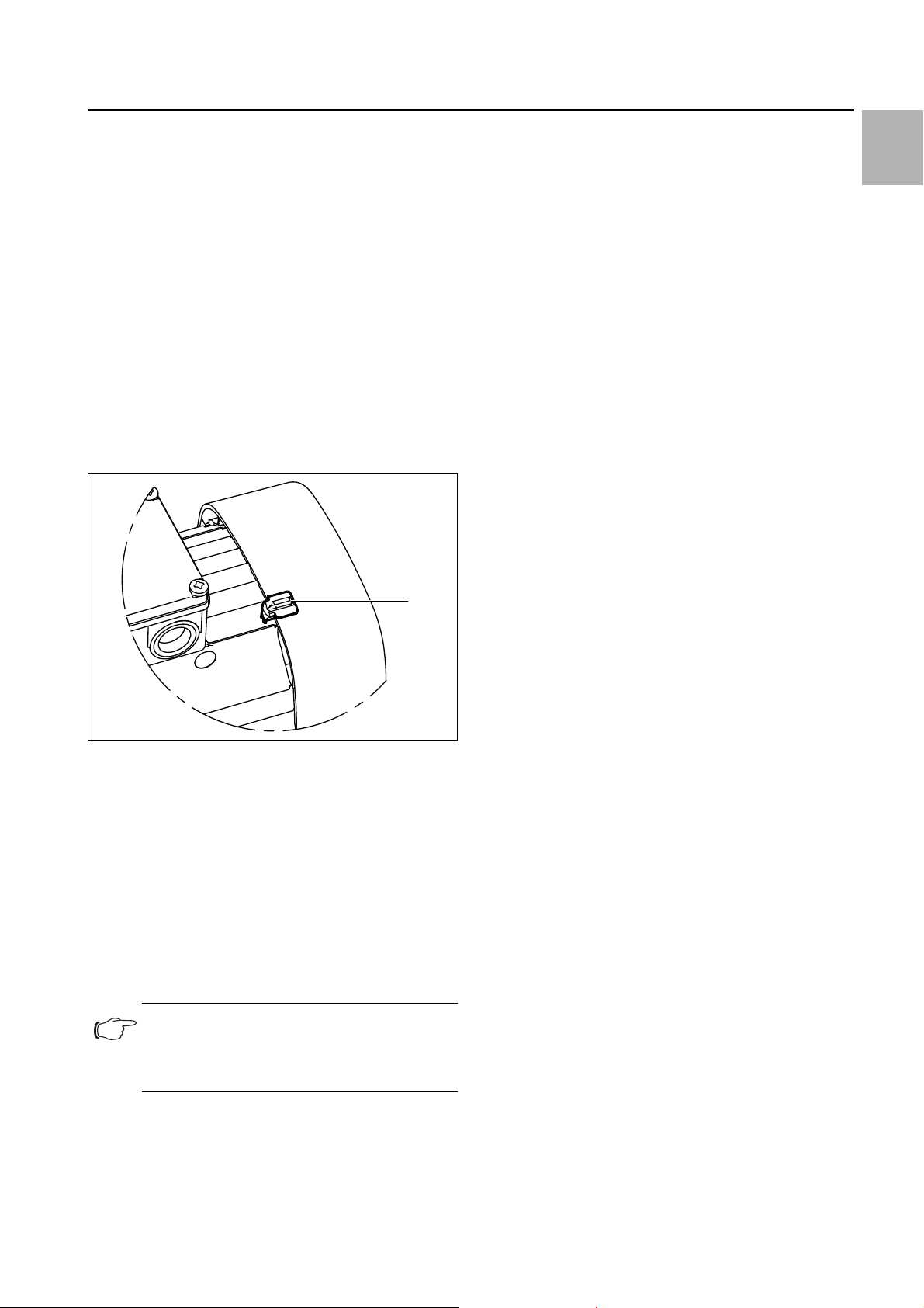
Check the direction of rotation of the motor in the cool-
ing medium pump.
The cover of the motor fan is equipped with a display
showing the direction of rotation (fig. 22). The motor
cooling air is used for the rotation direction display.
The correct direction of rotation is also indicated by arrows on the motor fan cover.
Fig. 22: Checking the direction of rotation
Key
1 Rotation direction display
If required, the condenser fan is activated by the temperature controller.
6.5 Adjusting the bypass valve
A bypass valve should be connected between the inlet
and return to protect the cooling medium pump (fig. 2 or
fig. 4, item 10). This opens automatically, for example, if
the equipment cycle is shut off. The bypass valve must
be adjusted to suit the requirements of the customer's
application.
Open the cover cap of the bypass valve by rotating in
a counter-clockwise direction.
Open the bypass valve by rotating in a counter-clock-
wise direction.
Vent the cooling medium pump (see section6.3
"Bleeding the cooling medium pump") and switch it
on.
Shut off the water flow to the customer application
completely using a customer-supplied shut-off valve in
the pipeline or in the end application.
On the chiller display, the current volumetric flow passing through the bypass is shown to the right of the
temperature reading (fig. 23, item 3).
Slowly close the bypass valve by rotating in a clock-
wise direction until the required flow rate is shown on
the display.
The factory setting is 5…6 l/min at 50 Hz. If a lower
value is set, the flow sensor will actuate an alarm message and the pump will stop.
If the pump stops due to an insufficient flow rate, open
the bypass valve by approximately another ¼ turn (approximately).
Close the cover cap of the bypass valve and open the
customer-supplied shut-off valve.
7 Operation
EN
To determine whether the motor’s direction of rotation is
correct, compare the display with the information in the
following list.
– Display panel "black": Direction of rotation correct
– Display panel "white/reflective": Direction of rotation
incorrect
If the direction of rotation is incorrect, you will need to
change over the connections for phases L1 and L2 on
the chiller's power supply connector.
Note:
If the compressor does not start up, the tem-
perature of the coolant added is lower than
the setpoint temperature.
7.1 General
The chiller is switched on and off by the higher-level control. It operates automatically, i.e. the cooling medium is
pumped continuously and heat extracted from it during
this process.
When switching on the unit, or following a malfunction,
the compressor has an ON delay of 3 minutes, and
starts with a reduced compressor output of 33% for 3
minutes. The compressor then enters control mode. If
there is a sudden cooling load demand, therefore, cooling medium temperatures may be increased during the
startup process.
The chiller is equipped with a touch function display for
making basic settings and displaying error messages.
This is an industrial-grade touch display which is pres-
If necessary, lower the setpoint temperature momen-
tarily (see section7.2.2 "Changing a parameter val-
ue").
The cooling air is drawn in from the front and expelled to
the rear.
Rittal Chiller Blue e+ 21
sure-sensitive and may therefore be operated with
gloves.
As well as operating directly on the chiller itself, there is
also a smartphone app available. This offers almost the
same functions as the actual display, and additionally
Page 22

7 Operation
EN
provides extended explanations of error messages, as
well as the option of contacting the Rittal Service team
directly.
Note:
Use the RiDiag software or an online tool,
available on the Rittal website, to check
whether the latest firmware version has
been installed.
7.2 Layout of the display
The display is divided into a top section on a dark background, and a bottom section with the menu bar. This
layout is always identical, but the content of the two sections will vary according to the menu selected.
7.2.1 Start screen
The start screen is always displayed while the cooling
unit is in normal operation, provided there are no error
messages.
Item Description Possible icons
8 Tank heater active (op-
tion)
9 Type of cooling: Active,
free cooling (option),
standby
10 Controlled by an inter-
nal or external sensor
11 External sensor (acces-
sory)
12 Info menu
13 System messages
(where applicable)
14 Service icon (if re-
quired)
15 Configuration
Fig. 23: Layout of the start screen
Key
Item Description Possible icons
1 Current medium tem-
perature (3-digit)
2EER value: Range
0…10
3 Water flow: Range
0…40 l/min
4 Display temperature
unit
5 USB connection (if
connected)
Numbers from 0-9
Tab. 9: List of all icons with descriptions
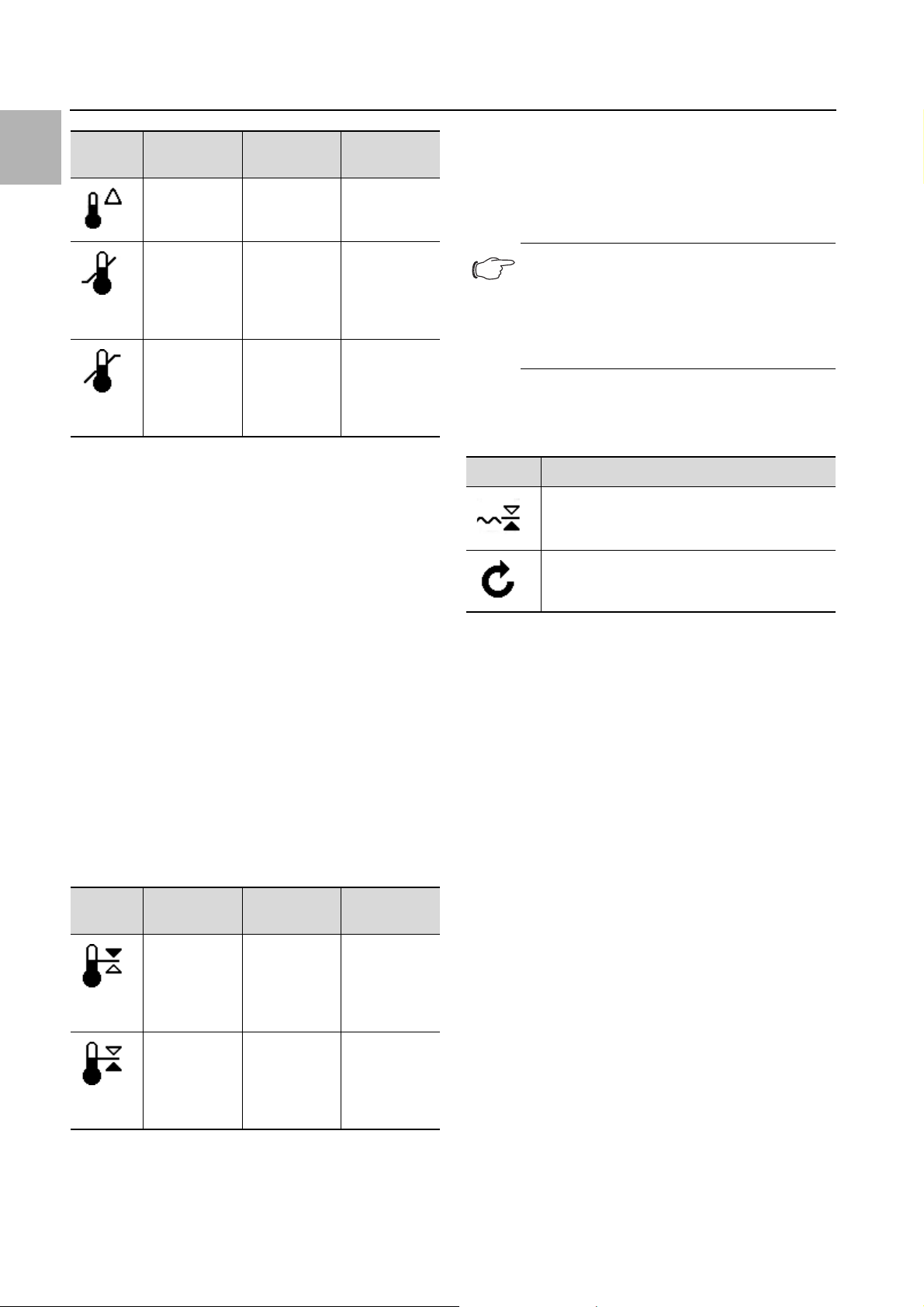
Type of cooling
The current form of cooling is indicated by one of the following four icons.
Symbol Parameter
Cooling active.
Cooling with the compressor switched off
("free cooling" option) or hybrid mode.
No cooling (standby).
Tab. 10: Possible icons for the current type of cooling
7.2.2 Changing a parameter value
If a parameter value is changed, the display including the
menu bar will also change.
6 Self-test (if initiated)
7 NFC connection (max.
120 seconds after connecting)
Tab. 9: List of all icons with descriptions
22 Rittal Chiller Blue e+
Page 23

Fig. 24: Screen for changing a parameter value
1
Key
1Main screen
2 Control bar
7 Operation
Exit the information screen by clicking on the "Back"
button.
7.3 Info menu
Click on the "Info" symbol to display a list of lower-level
screen pages.
Symbol Parameter
Temperature info
Device info
EN
The currently selected parameter value is displayed in
the centre of the main screen. To change this value, you
always proceed in the same way, as described below
with the example of adjusting the set temperature:
On the start screen, click on the "Configuration" but-
ton.
Enter the PIN to gain access to the lower-level screen
pages of the "Configuration" zone.
"22" is the default PIN.
Click on the "Temperature" symbol.
Click on the "Control mode" symbol.
Select your preferred control mode from the display.
Change the setting to the required temperature using
the "Up" and "Down" arrows.
Alternatively, you can also select the one of the dis-
played higher or lower values directly.
Finally, confirm the set value with "OK".
Exit this screen page with the "Back" button.
7.2.3 Help function
A help function is offered on selected screens. On these
pages, an "info symbol" is visible in the top right-hand
corner.
Efficiency info
Hydraulic info
Tab. 11: "Info" zone
7.3.1 Temperature info
Click on the "Temperature info" symbol.
A list of different temperature values will be displayed.
Page through the list using the "Up" and "Down" ar-
rows.
Symbol Parameter
Av. medium 24h
Average medium temperature over the last 24
hours of operation.
Av. ambient 24h
Average ambient temperature (external temperature) over the last 24 hours of operation.
Current setpoint
Current temperature setpoint, depending on
the chosen control mode.
Thresh. Overtemp.
Temperature limit which will trigger an alarm
message if exceeded.
Tab. 12: "Temperature info" zone
7.3.2 Device info
Click on the "Device info" symbol.
A list of general information about the device will be
Fig. 25: Screen with help function
Key
1Info symbol
Click on the info symbol at the top right of the page.
displayed.
Page through the list using the "Up" and "Down" ar-
rows.
An information screen showing further information
about the relevant parameters will be displayed.
Rittal Chiller Blue e+ 23
Page 24

7 Operation
EN
Symbol Parameter
Article number
Serial number
Manufacture date YYYY-MM-DD
Hardware release x.xx.xx
Firmware release x.xx.xx
Software release x.xx.xx
Last update YYYY-MM-DD
L. maintenance YYYY-MM-DD
User device name
Name assigned to the cooling unit by the customer. This title can be assigned using the
RiDiag software or the Blue e+ app to distinguish between individual units.
Act. control mode
Tab. 13: "Device info" zone
7.3.3 Efficiency info
Click on the "Efficiency info" symbol.
Click on the "Efficiency info" symbol.
The average energy efficiency ratio (EER) for the last
24 hours of operation will be displayed. The energy efficiency ratio is the ratio of the cooling output generated to the electrical power used.
Note:
The power consumption of the cooling medi-
um pump is not included in the calculation of
the EER value (see section12.3 "Technical
specifications").
Symbol Parameter
Efficiency info
Average energy efficiency ratio (EER) of the last
24 hours of operation.
Tab. 14: "Efficiency info" zone
7.3.4 Hydraulic info
Click on the "Hydraulic info" symbol.
A list of information about the cooling circuit will be displayed.
Page through the list using the "Up" and "Down" ar-
rows.
Symbol Parameter
Water flow
Current flow rate of the cooling medium in
l/min.
Tab. 15: "Hydraulic info" zone
7.4 Configuration menu
Click on the "Configuration" symbol.
A screen page will appear asking you to enter the PIN
in order to access the lower-level screen pages.
Note:
"22" is preset in the factory as the default
PIN.
For the first digit, page through the digits "0" to "9" us-
ing the "Up" and "Down" arrows until the required digit
appears in the box.
Confirm your selection with "OK".
For the second digit, once again page through the dig-
its "0" to "9" using the "Up" and "Down" arrows until
the required digit appears in the box.
Confirm your selection with "OK".
A list of lower-level screen pages will be displayed.
Symbol Parameter
Control param.
Settings for set temperature and control mode
Remote
Settings for evaluating the external enabling
signal
Network
Display of network information from the IoT interface (3124300)
Alarm relay
Settings for the alarm relays.
Tab. 16: "Configuration" zone
24 Rittal Chiller Blue e+
Page 25

7 Operation
Symbol Parameter
Filter mats
Display language
Choice of language for display texts.
Self-test
Perform a self-test.
Tab. 16: "Configuration" zone
7.4.1 Control parameters
Click on the "Control parameters" symbol to display a
list of lower-level screen pages.
Symbol Parameter
Temperature
Settings for set temperature and control mode
Water flow
Setting of alarm limits and start-up attempts.
Temperature > Control mode
The chiller can control cooling output according to one
of the following two temperature values:
– Cooling medium temperature (fixed value): Tem-
perature of the cooling medium.
– External temperature sensor: If the "External tem-
perature sensor" is installed as an accessory, temperature control of the cooling medium can also be based
on the temperature in the room where the chiller is located.
Note:
The external temperature sensor is available
as accessory from Rittal (see section 11 "Accessories").
Click on the "Control mode" symbol.
The setpoint for the currently set control mode is displayed.
Choose your preferred control mode by selecting it
from the display:
Symbol Parameter
Medium temp.
EN
Heating (optional)
If the "tank heater" option is installed, the relevant settings may be made here.
Cooling medium
Tab. 17: "Control parameters" zone
Temperature
Click on the "Temperature" symbol to display a list of
lower-level screen pages.
Symbol Parameter
Change unit
Set the unit "°C" or "°F"
Control mode
Alarm threshold
Temperature limit which will trigger an alarm
message if exceeded.
Tab. 18: "Temperature" zone
Temperature > Unit
All temperature values for the unit may be displayed either in degrees Celsius "°C" or degrees Fahrenheit "°F".
Click on the "Change unit" symbol.
Change the required unit ("°C" or "°F") using the "Up"
or "Down" arrows.
Confirm your entry with "OK".
External sensor (accessory)
Tab. 19: "Control mode" zone
The corresponding symbol for the chosen control mode
is likewise displayed on the overview page.
Temperature > Control mode > Medium temperature
Click on the "Medium temperature" symbol.
The currently set medium temperature is displayed.
Change the setpoint using the "Up" and "Down" ar-
rows or select the required medium temperature directly.
Confirm your selection with "OK".
Temperature > Control mode > External sensor
Please observe the following when selecting the sensor
position:
– Where possible, the temperature sensor should not be
placed in direct sunlight or in an air current.
Click on the "External sensor" symbol.
The prescribed temperature values for controlling the
cooling medium temperature are displayed with the
aid of the external temperature sensor.
Choose the required parameter by selecting it from the
display:
Rittal Chiller Blue e+ 25
Page 26
EN
7 Operation
Symbol Parameter Setpoint Factory
setting
Diff. to ext.
temp.
-10 K
…
10 K
5K
Choose your preferred type of alarm threshold (over-
temperaure or undertemperature) by selecting it from
the display.
Change the setpoint using the "Up" and "Down" ar-
rows or select the required temperature directly.
Confirm your entry with "OK".
5°C (41°F)
Min.
temperature
Max.
temperature
Tab. 20: "External temperature sensor" zone
Change the setpoint using the "Up" and "Down" ar-
…
current
maximum
temperature
Current
minimum
temperature
…
35°C (95°F)
10°C (50°F)
28°C (82°F)
rows or select the required temperature directly.
Confirm your entry with "OK".
With the factory settings, the cooling medium temperature is controlled depending on the value measured by
the external temperature sensor, within the following limits:
1. The temperature of the cooling medium is 5 K above
the measured temperature value.
2. However, if the measured temperature value drops
below 5°C (41°F), the temperature of the cooling
medium will remain at 10°C (50°F).
3. However, if the measured temperature value rises
above 23°C (73°F), the temperature of the cooling
medium will remain at 28°C (82°F).
Temperature > Alarm threshold
This threshold value is used for an alarm message (overtemperature or undertemperature). The set value must
therefore be above or below the actual setpoint to which
the cooling unit has been set.
Symbol Parameter Alarm
threshold
Factory
setting
Note:
At a water temperature of +2°C, the pump is
automatically switched on, and switched off
again at +5°C. This frost protection function
is always active, regardless of whether or not
it has been enabled externally.
Water flow
Click on the "Water flow" symbol to display a list of
lower-level screen pages.
Symbol Parameter
Alarm threshold
Lower flow rate threshold, below which a message is emitted.
Reset flow sensor
Tab. 22: "Water flow" zone
Water flow > Alarm threshold
This threshold value is used for a message (insufficient
flow rate).
Standard value: 5 l/min for all output categories.
Click on the "Alarm threshold" symbol.
Change the setpoint using the "Up" and "Down" but-
tons or select the required flow rate (5…15 l/min) directly.
Confirm your entry with "OK".
Water flow > Alarm threshold
Below a fixed limit of 4 l/min, the cooling function and the
pump are switched off. An alarm is set.
Reset the error as described in the following section.
+2 K
Over-
temperature
Subnormal
temperature
Tab. 21: "Alarm limit“ zone
Click on the "Alarm threshold" symbol.
26 Rittal Chiller Blue e+
(+3.6°F)
…
+15 K
(+27°F)
-2 K
(-3.6°F)
…
-15 K
(-27°F)
5K
(9°F)
Off
Water flow > Reset flow sensor
If the flow rate is too low (≤ 4 l/min), a corresponding
alarm message will appear on the display. In "Manual reset" mode, this message must be manually reset before
the pump will restart. In "Automatic reset" mode, a preset number of automatic restarts will occur.
Click on the "Reset flow sensor" symbol.
Choose the required mode by selecting it from the dis-
play.
Page 27

Symbol Parameter
Manual reset
Automatic reset
Tab. 23: "Reset flow sensor" zone
If "Automatic reset" mo de is activated, you will also need
to set the number of possible restarts.
For "Automatic reset" mode, indicate how often the er-
ror message should be automatically reset (between
once and five times).
"2 restarts" is preselected here as the default.
Heating (optional)
If the tank heater (optional) is installed for frost protection
or to preheat the cooling medium, this can be activated
or deactivated here.
Click on the "Heating" symbol.
Activate the heater by selecting "On", or deactivate the
heater by selecting "Off" (default setting).
7 Operation
The heater therefore cuts in and out at the following temperatures:
– Switching on: Setpoint temperature of cooling
medium - switch-on hysteresis
– Switching off: Activation temperature of heater +
switch-off hysteresis
Example:
– Setpoint temperature: 38°C
– Switch-on hysteresis: 3.0 K
– Switch-off hysteresis: 2.0 K
In this case, the heater is switched on and off at the fol-
lowing temperatures:
– Switch-on temperature: 38°C-3.0 K = 35°C
– Switch-off temperature: 35°C+2.0 K = 37°C
Cooling medium
Click on the "Cooling medium" symbol to display a list
of lower-level screen pages.
Symbol Parameter
Water/demi water (option)
EN
Heating > Heating control
If you have activated the heater, the screen page "heating control" will appear.
Select the desired parameter.
A screen page similar to the one requesting the PIN for
access to the lower-level screen pages of the configuration menu will appear.
Symbol Parameter Range Factory
setting
1.0 K
Hyst. turn-on
Hyst. turn-off 0.5 K…3.0 K 2.0 K
Tab. 24: "Hysteresis values" zone
One by one, enter the three digits for the hysteresis
…
10.0 K
3.0 K
value and confirm each one with "OK".
Please remember that the value for the switch-on hys-
teresis of the heater must always be higher than the
value for the switch-off hysteresis.
Note:
When the heater is activated, at a water tem-
perature of +2°C, the pump and heater are
automatically switched on, and switched off
again at +5°C. This frost protection function
is always active, regardless of whether or not
it has been enabled externally.
Water-glycol mix
Oil/emulsion (option)
Tab. 25: "Cooling medium" zone
Cooling medium > Water-glycol mix
Here, you specify the glycol proportion of the cooling
medium if you are using a water/glycol mixture.
Click on the "Water-glycol mix" symbol.
Change the glycol proportion using the "Up" and
"Down" buttons or select the required value directly.
A glycol proportion of between 20% (indoor) and 34%
(outdoor) may be selected.
This setting will affect the EER calculation. 20% is pre-
set as the default.
Confirm your entry with "OK".
Cooling medium > Oil/emulsion
If you use the "Cooling medium oil/emulsion" option, you
will need to specify the specific thermal capacity of the
cooling medium here.
Click on the "Oil/emulsion" symbol.
A screen page similar to the one requesting the PIN for
access to the lower-level screen pages of the config-
uration menu will appear.
Enter the two digits for the thermal capacity, confirm-
ing each one with "OK".
The thermal capacity can be set between 1.0 … 4.9.
The default setting is 2.8.
Rittal Chiller Blue e+ 27
Page 28

EN
7 Operation
7.4.2 Remote
Click on the "Remote" symbol.
Select how you want the external enabling signal to be
evaluated.
Symbol Parameter
Network off
Symbol Parameter
Off The chiller is permanently in operational
readiness, i.e. the external enabling signal is
not used (default setting).
Standby The cooling function and the cooling medi-
um pump are deactivated.
Cooling off The cooling function is deactivated, the cool-
ing medium pump remains on so that the
cooling medium continues to circulate.
Relay function1
Relay function2
Relay function3
Tab. 26: "External enabling signal" zone
The chiller switches to standby mode in the
absence of a signal. If the chiller is in standby
mode, alarm relay 1 (contacts 8 and 9 on
signal connector X2) will open.
The chiller switches to standby mode in the
absence of a signal. If the chiller is in standby
mode, alarm relay 2 (contacts 8 and 10 on
signal connector X2) will open.
The chiller switches to standby mode in the
absence of a signal. If the chiller is in standby
mode, alarm relays 1 and 2 (contacts 8, 9
and 10 on signal connector X2) will open.
7.4.3 Network
Click on the "Network" symbol to display a list of low-
er-level screen pages.
Network on
Tab. 28: Data communication settings
Network info
Get IP information about how the IoT interface is incorporated into the network.
Click on the "Network info" symbol to display a list of
lower-level screen pages.
Symbol Parameter
IPv4
IPv6
Tab. 29: Select the protocol version
IPv4
Click on the "IPv4" symbol.
A list of general information about the IPv4 settings will
be displayed.
Page through the list using the "Up" and "Down" ar-
rows.
Symbol Parameter
Network on/off
Network info
Tab. 27: "Network" zone
Network on/off
Here, you can activate / deactivate data communication
to the IoT interface. Data communication is activated by
default.
Click on the "Network on/off" symbol.
Select your preferred setting by selecting it from the
display.
Confirm your entry with "OK".
Parameter Setting
DHCP off/on
IP address xxx.xxx.xxx.xxx
Network
mask
Router
address
Tab. 30: IPv4 settings
xxx.xxx.xxx.xxx
xxx.xxx.xxx.xxx
IPv6
Click on the "IPv6" symbol.
A list of general information about the IPv6 settings will
be displayed.
Page through the list using the "Up" and "Down" ar-
rows.
Click on the desired entries to display the IPv6 ad-
dresses.
Parameter Setting
DHCP off/on
Tab. 31: IPv6 settings
28 Rittal Chiller Blue e+
Page 29
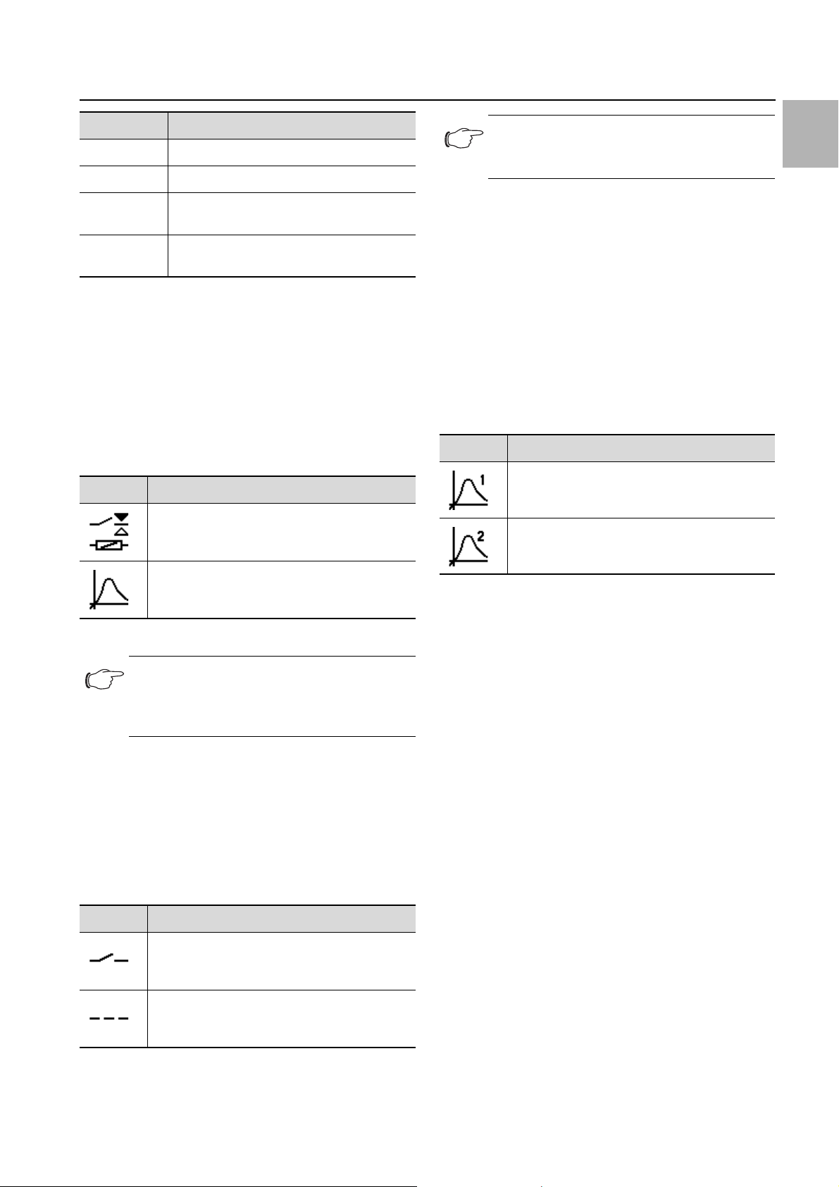
7 Operation
Parameter Setting
IP address 1 …
IP address 2 …
Auto
address
Link-local
addr.
Tab. 31: IPv6 settings
…
…
7.4.4 Alarm relays
There are two floating relay outputs in the connection
box on the rear of the unit, which may be used to output
system messages from the chiller to an external signal
source (see section5.6.2 "Connecting the alarm relay
query device"). The relay outputs may be configured
here.
Click on the "Alarm relay" symbol to display a list of
lower-level screen pages.
Symbol Parameter
Switch NO/NC
Switch the alarm relay as a normally closed or
normally open contact.
Note:
The factory setting of the relay outputs in their
de-energised state is NO (Normally Open).
Function list
This is where you specify which error messages should
lead to switching of the respective relay output.
Click on the "Relay 1" or "Relay 2" symbol, and select
the alarm relay to which you wish to assign a function.
From the list of errors, select the function which should
cause the previously selected relay output to switch.
If applicable, assign further functions to the relay out-
put, and the output will then be switch if at least one
of the assigned functions leads to an error message.
Confirm your entry with "OK".
If applicable, configure the other relay output with oth-
er functions.
Symbol Parameter
Assign relay 1
Assign relay 2
EN
Function list
Allocation of a function to the respective alarm
relay.
Tab. 32: "Alarm relay" zone
Note:
For the factory setting of alarm relay alloca-
tion see section 9.1 "List of system messages" (tab. 36).
Switch NO/NC
The switch logic of the relay output, i.e. whether it is to
be used as a normally closed or normally open contact,
may be set here.
Click on the "Switch NO/NC" symbol.
Choose your preferred switch logic by selecting it from
the display.
Confirm your entry with "OK".
Symbol Parameter
Normally Open
Switch the alarm relay as a normally open contact.
Normally Closed
Switch the alarm relay as a normally closed
contact.
Tab. 34: Function list
7.4.5 Language settings
All displays on the unit are available in 21 different languages.
Click on the "Display language" symbol.
Page through to the required language using the "Up"
and "Down" arrows.
Confirm the chosen language with "OK".
The language will change over immediately, and all
menu displays will appear in the chosen language.
7.4.6 Self-test
In the event of a malfunction in the unit which fails to produce an error message, it may be useful to check the
key functions of all components with a self-test. You
may continue to operate the unit as normal while the
self-test is being carried out.
Click on the "Self-test" symbol.
Confirm the start of the self-test with "OK".
While the self-test is being carried out, a progress indicator will appear on the display. Once the test is complete, either the message "Unit OK" or "Check error" will
be displayed.
If applicable, use the error list to determine which mal-
function applies.
Tab. 33: Switch logic of the alarm relay
Rittal Chiller Blue e+ 29
Page 30
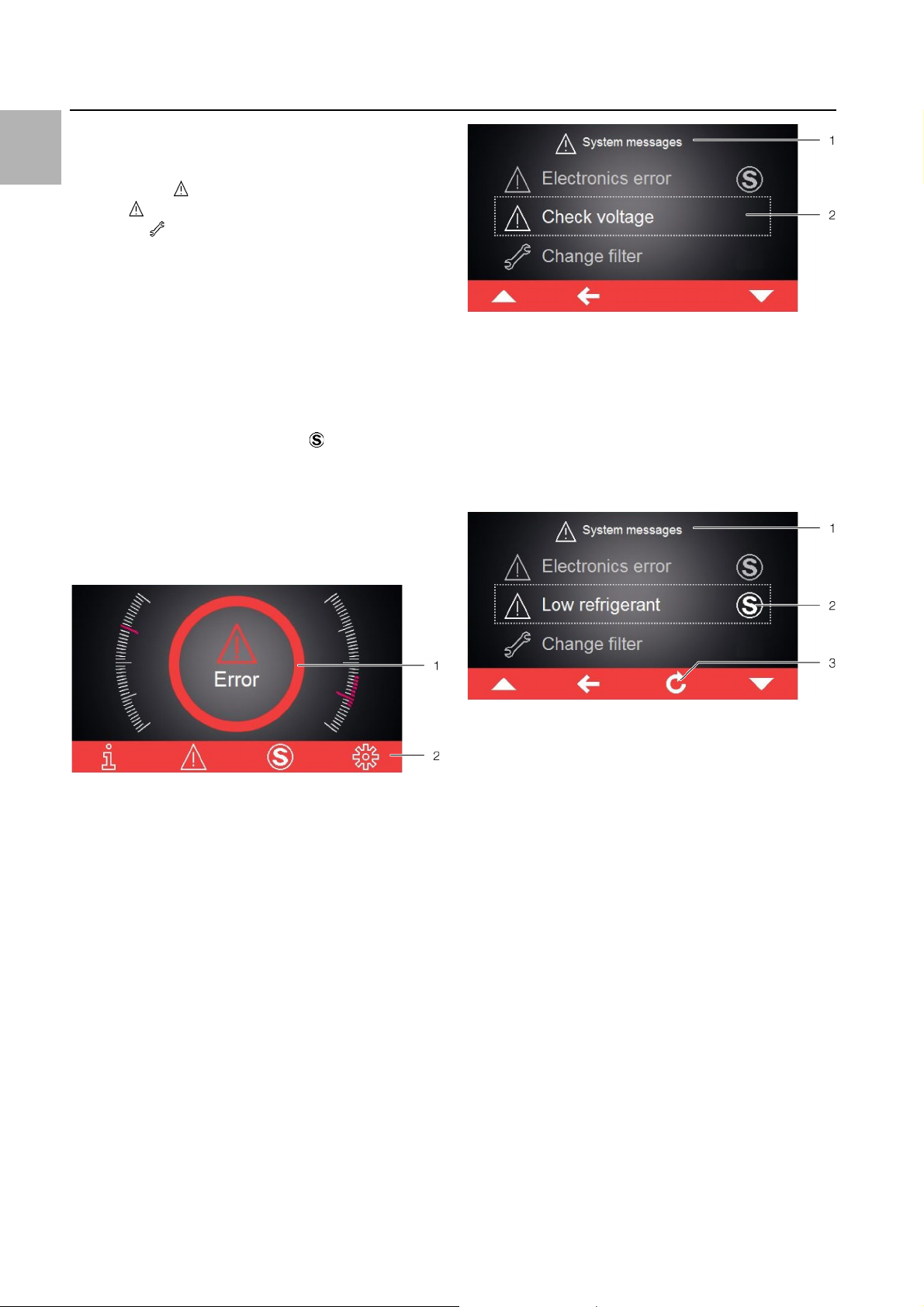
EN
8 Inspection and maintenance
7.5 System messages
We distinguish between three different types of system
messages on the unit:
–Malfunctions
–Errors
– Servicing
If a corresponding message applies, the "System mes-
sages" symbol is displayed in the menu bar (fig. 23,
item 13). A list of all possible system messages may be
found in section9.1 "List of system messages".
Click on the "System messages" symbol.
A list of all active system messages will be displayed.
The individual messages are arranged in ascending order as they occur according to the above three categories.
If an error message can only be resolved by the Rittal
Service team, the "Service" symbol will additionally
appear after the error message.
In such cases, please contact Rittal Service (see sec-
tion9 "Troubleshooting").
7.5.1 Occurrence of a malfunction
In the event of a malfunction, the start screen will be superimposed with an error message.
Fig. 27: Screen showing error messages
Key
1 "Errors" menu
2 Error message
If an error message applies that cannot be resolved by
the operator himself and which is not reset automatically, the "Service" symbol will appear after the error message and in the control bar next to the symbol for system
messages (fig. 28, item 2).
Fig. 26: Screen in the event of a malfunction
Key
1Superimposed
2 Menu bar in red
The start screen is superimposed with this message in
the event of a device malfunction:
If the malfunctions cannot be resolved by the operator
himself, the Service symbol will additionally be displayed
(fig. 23, item14).
Contact the Rittal Service team if you are unable to re-
solve the malfunction yourself (see section9 "Troubleshooting").
7.5.2 Display in case of errors
If errors have occurred or servicing is required, the "System messages" symbol will appear in the menu bar (see
section7.5 "System messages").
Most system messages are reset automatically once the
fault has been resolved.
Fig. 28: Screen showing error messages
Key
1 "Errors" menu
2 Error message
3 "Return" button
Contact Rittal Service (see section9 "Troubleshoot-
ing").
Acknowledge the error message by pressing the "Re-
turn" button.
8 Inspection and maintenance
Proper, regular inspections and maintenance (once a
year is recommended) and usage of original spare parts
only are crucial for problem-free operation and a long
service life of the chiller.
We therefore recommend a maintenance contract.
We offer maintenance service.
Our service contact:
Phone: +49 2772 505-1855
Fax: +49 2772 505-1850
E-mail: service@rittal.de
30 Rittal Chiller Blue e+
Page 31
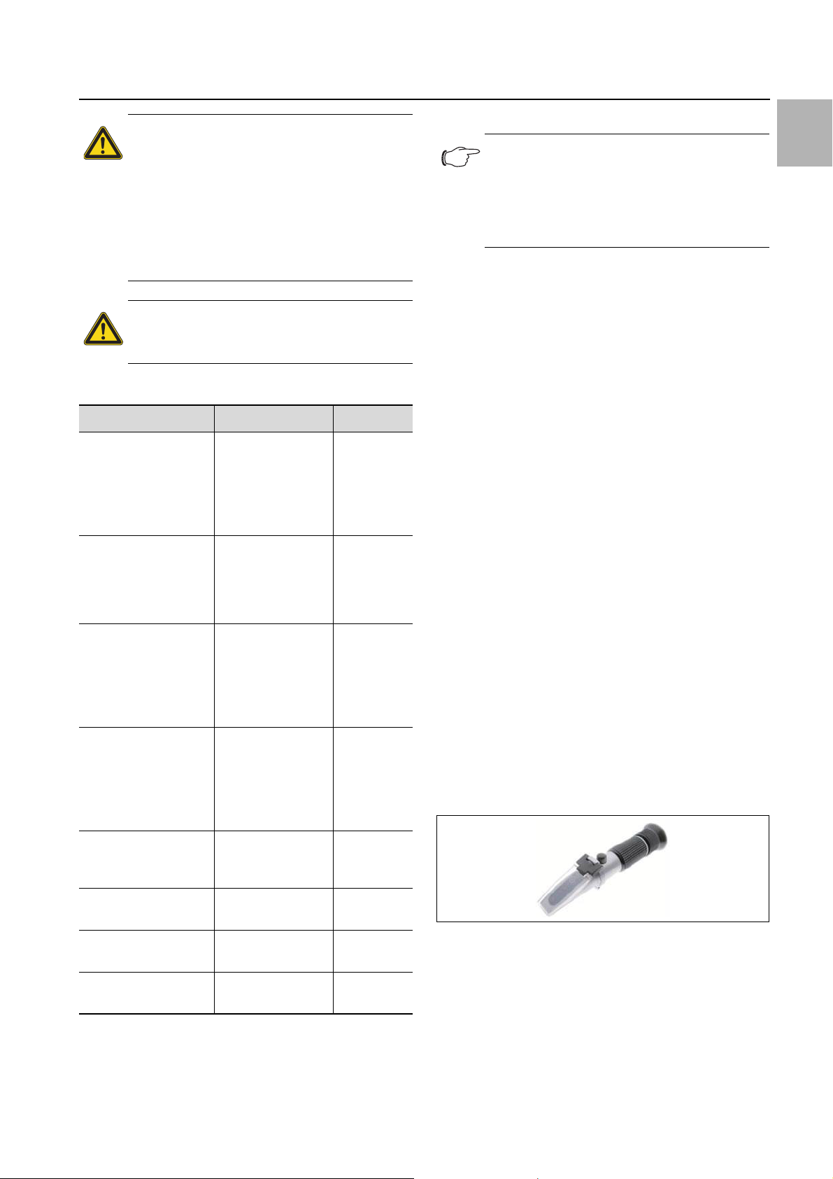
8 Inspection and maintenance
Danger!
Risk of electric shock at live connections!
Prior to any inspection and maintenance
work, the chiller must be disconnected
from the power supply.
When the master switch is switched off,
the alarm relay is still live. Disconnect
signal connector X2 as well.
Caution!
Never use flammable liquids for cleaning.
Overview of the inspection and maintenance tasks
Assembly Task Interval
Cooling medium level Check for sufficient
filling, top up if
necessary.
Filter mat (accessory) Clean or replace fil-
ter mat.
Cooling medium Check cooling me-
dium circuit for
soiling and any foreign bodies (chips
and the like).
Check mix ratio.
Tank, components,
and all connections
(piping, valves and fittings, hoses) in the
circuit for the equipment to be cooled
Check for leaks. 4 weeks
When indicated on
the display
or via the
alarm relay
contact
4 weeks or
depending
on the level
of contamination
4 weeks
8.1 Maintaining the refrigerant circuit
EN
Note:
The refrigerant circuit is filled with a compar-
atively small quantity of refrigerant (< 3.5 kg).
This means that maintenance to the cooling
circuit (such as regular leak checks) is not
generally needed.
As a hermetically sealed system, the refrigerant circuit
has been filled in the factory with the required amount of
refrigerant, tested for leaks and subjected to a function
test run.
Maintenance tasks on the refrigerant circuit are only allowed to be undertaken by a specialist refrigeration
company. We recommend a maintenance contract that
includes an annual inspection of the refrigerant circuit
(European regulation EC no. 517/2014 / fluorinated
greenhouse gases).
8.2 Monitoring the cooling medium
The fill level of the cooling medium tank is monitored with
a level switch. If the fill level drops below the lower limit,
a corresponding message will appear on the display (see
section9.1 "List of system messages").
Top up with cooling medium as soon as possible if in-
dicated by a message on the display.
Regularly check the quality of the cooling medium, and
if necessary, improve it as described under sec-
tion6.1.3 "Preparation and care" beschrieben.
Regularly measure the glycol content with the aid of a
refractometer (fig. 29). If you have any questions about
this, please contact our service department.
In order to prevent the formation of fungus and algae,
the cooling medium should be replaced at least once
a year. The use of pure water may also cause the for-
mation of fungus or algae.
If the chiller is used under certain physical conditions (Tw
< 10°C), condensation may form in the system. This can
be minimised by means of suitable insulation or the optionally available room-temperature-based control.
Condenser (aircooled)
Condenser fan (aircooled)
Cooling medium Replace cooling
Condenser (watercooled)
Tab. 35: Inspection and maintenance tasks
Rittal Chiller Blue e+ 31
Clean fins using
compressed air, or
with a brush.
Check noise generation, clean.
medium.
Check for adequate flow rate.
3 months
6 months
1 year
1 year
Fig. 29: Refractometer
Page 32
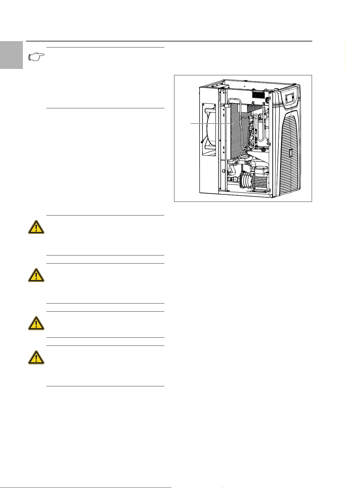
8 Inspection and maintenance
1
EN
Note:
The manufacturer's guarantee and liability
will be rendered void in cases of incorrect use
and treatment of the chiller. To prevent problems in the cooling medium circuit (including
water-cooled chillers), it is imperative that the
VGB Cooling Water Guidelines (VGB-R 455
P) are observed.
8.3 Cleaning the condenser
To ensure the correct function of the chiller, the fins on
the air-cooled condenser must be kept clean. It must be
cleaned at regular intervals of at least every three
months; the frequency of cleaning depends on the degree of soiling in the rooms where the unit is installed.
Ambient air containing oil in conjunction with dust will result in increased soiling of the condenser fins. In such
cases, thorough cleaning with compressed air is only
possible under certain circumstances. In such cases,
the additional use of a metal filter mat is required (see
section11.4 "Metal filter (aluminium filter)").
When cleaning, it is imperative to observe the following
warning and safety notes below.
Danger!
Prior to any inspection and maintenance
work, the chiller must be disconnected
from the power supply at the master
switch.
Danger!
Temperatures of up to 60°C may occur
inside the chiller. Wait approx. 10 min.
after you have switched off the chiller to
allow the pipe to cool down.
Risk of cuts!
Sharp-edged condenser fins! Use gloves
as personal protection equipment.
Caution!
Risk of damage for the condenser fins
due to powerful compressed air!
Use the compressed air carefully to
avoid damage.
Raise the side covers of the chiller slightly with the
handles and remove them.
This will give you access to the condenser at the cen-
tre of the chiller.
Fig. 30: Cleaning the condenser (shown here: 3334300)
Key
1Condenser
Use compressed air or a vacuum cleaner with the
brush attachment to clean the condenser.
8.4 Cleaning the filter mat (accessories)
Metal filter mats may be washed with water or greasedissolving detergents. Textile filter mats and the pleated
filter in front of the inverter housing must be replaced at
regular intervals (see section5.7 "Installing the filter mats
(accessories)").
At the front of the chiller, pull the louvred grille away
from the mounting clips, and place or lay it down
somewhere safe.
Remove the filter mat in front of the air intake grille on
the chiller.
Clean the metal filter mats e.g. using water and de-
greaser/detergent.
Place the cleaned metal filter mat or a new textile filter
mat in front of the air intake grille on the chiller.
Press the louvred grilles back onto the mounting clips.
Replace the pleated filter in front of the inverter hous-
ing accordingly.
When cleaning, please proceed as follows:
Electrically isolate the chiller at the master switch.
Secure the master switch to prevent it being switched
back on.
Remove the chiller cover by pulling upwards.
32 Rittal Chiller Blue e+
8.5 Draining the cooling medium tank
Drain the cooling medium tank via the tank drain noz-
zle (fig. 2, item 7) either directly or using a hose into a
container.
When disposing of the cooling medium, observe the
locally application regulations on water pollution.
Page 33

9 Troubleshooting
In operation, the chiller operates in a safe state. The chiller maintains the cooling medium inlet temperature at the
setpoint set.
Possible causes for deviation from the setpoint could be:
– Cooling demand too high
– Ambient temperature too high
– Failure to observe required distances
– Clogged evaporator coil
– Flow rate too low or too high
– Soiled condenser
– Lack of refrigerant
– Level of cooling medium in tank too low
– Cooling medium temperature set too low
– Parameters set incorrectly
The malfunctions are only allowed to be rectified by suitably instructed, qualified personnel.
For information on malfunction analysis, refer to tab. 36
"Error messages" or contact our service department:
Service contact:
Rittal International Service
Auf dem Stützelberg
35745 Herborn
9 Troubleshooting
EN
Phone: +49 2772 505-1855
Fax: +49 2772 505-1850
E-mail: service@rittal.de
Rittal Chiller Blue e+ 33
Page 34

9 Troubleshooting
EN
9.1 List of system messages
The applicable error messages are displayed with the
Contact details for the Rittal Service team can be found
in section9 "Troubleshooting".
corresponding symbol in the Errors list (see section 7.5
"System messages"). Extended information for resolving
individual faults may be found in this section.
System message Alarm relay output
(factory setting)
Med.temp. too high – The measured medium temperature (water outlet) is above the set
Med.temp. too low – The measured medium temperature (water outlet) is below the set
Change filter – The filter mat in your chiller is dirty. Please replace or clean the filter mat
Clean condenser – The condenser in your chiller is dirty. Please remove the roof plate and
Troubleshooting measures/solutions
alarm limit for your chiller.
Please check any maintenance and error messages, and check the
design of your cooling unit. For any further questions, please contact
Rittal Service directly.
alarm limit for your chiller.
Please check any maintenance and error messages, and check the
design of your cooling unit. For any further questions, please contact
Rittal Service directly.
and confirm this by pressing reset in the list of system messages on
the chiller display.
side panels and clean the heat exchanger, e.g. using compressed air.
The error message will terminate automatically approximately 30 seconds after it has been resolved.
Air routing 1 The air inlet or outlet is blocked. Please remove the blockage and en-
sure that minimum distances from the air inlet or outlet to components
inside the enclosure are observed.
Exp. valve defect 2 The electronic expansion valve in your chiller is reporting a malfunction.
Please contact your Rittal Service.
Ext.temp. range 1 Your chiller is being operated outside of the admissible ambient tem-
perature. Please ensure that the ambient temperature does not exceed
the admissible range
Low refrigerant 2 Your chiller is reporting a lack of refrigerant in the active cooling circuit.
Please contact your Rittal Service.
Fan alarm 1 2 The fan in your chiller is blocked. Please check if you can see a block-
age and remove it. If no blockage is visible, please replace the fan. You
may order the required spare part directly from Rittal.
Fan alarm 2 2 The fan in your chiller is defective. Please replace the fan. You may or-
der the required spare part directly from Rittal.
Tab. 36: Error messages
34 Rittal Chiller Blue e+
Page 35
9 Troubleshooting
System message Alarm relay output
(factory setting)
Inverter cooling – The inverter heat sink in your chiller is dirty. Please remove the roof
Compressor defect 2 The compressor in your chiller is reporting a malfunction. Please con-
Sens. xx defect 2 Sensor xx in your cooling unit is reporting a sensor failure. Please con-
Ext.sens.xx miss. 1 The external sensor xx is not connected or has a malfunction. Please
Check voltage 2 You are operating your cooling unit outside of the admissible voltage
Troubleshooting measures/solutions
plate and side panels and clean the heat sink, e.g. using compressed
air.
The error message will terminate automatically approximately 30 seconds after it has been resolved.
tact your Rittal Service.
tact your Rittal Service.
check the connection or select another control mode.
ranges. Please check the power supply to the cooling unit and observe
the specifications on the rating plate.
EN
Electronics error 2 The electronics in your cooling unit are reporting an electronic fault.
Please contact your Rittal Service.
Check parameters – Due to an error, the chiller has been reset to the factory defaults.
Please check the current messages or contact your Rittal Service
team.
Inverter error 2 The inverter in your chiller is reporting a malfunction. Please contact
your Rittal Service.
Compressor phase 2 The compressor in your chiller is reporting a malfunction. Please con-
tact your Rittal Service.
Overload 1 Please check the rating of your chiller. For any further questions, please
contact your Rittal Service team directly.
Alarm act.cooling – The active cooling function of your unit is defective. Please contact
your Rittal Service.
Pump error 2 The motor circuit-breaker on the pump has tripped. Please contact
your Rittal Service.
Tab. 36: Error messages
Rittal Chiller Blue e+ 35
Page 36

10 Decommissioning and disposal
EN
System message Alarm relay output
(factory setting)
Warning icing – The evaporation temperature is too low. This may be because the flow
Alarm icing 2 The evaporation temperature is often or permanently too low. Please
Warn. tank level 1 The fill level of the tank is low and needs to be topped up.
CoolWatrSuppLow – Please check the cooling water supply to your unit.
Heating error 1 The integral safety thermostat in the heater has tripped. Please check
Error free cool. – Malfunction in the free cooling valve. Please check the valve for smooth
Troubleshooting measures/solutions
rate is inadequate or the setpoint is too low.
contact your Rittal Service.
the fill level in the water tank. If this message occurs repeatedly, please
contact your Rittal Service team.
running or contact your Rittal Service team.
Flow warning 1 The flow rate is lower than the set warning threshold value. Please
check the hydraulic circuit, water filter and tank fill level.
Flow alarm 2 The flow rate is lower than the alarm threshold value. Please check the
hydraulic circuit, water filter and tank fill level. If this message occurs
repeatedly, please contact your Rittal Service team.
Tab. 36: Error messages
10 Decommissioning and disposal
The chiller is only allowed to be shut down by authorised, qualified personnel. For this purpose the chiller
must be decommissioned.
10.1 Decommissioning
If the chiller is not to be used for an extended period
(more than 6 months) the cooling medium circuit must
be drained. This will prevent the evaporation of water,
and the water-glycol ratio of the cooling medium will not
Drain the cooling medium tank via the tank drain noz-
zle (fig. 2, item 7), either directly or using a hose, into a
container.
For disposal of the cooling medium, observe the appli-
cable regulations on water pollution.
Disconnect and dismantle the cooling medium circuit
connections.
To recommission the chiller, proceed as described in
section6 "Commissioning". Make the same checks
as described in that section.
be altered. If the glycol thickens, the cooling medium
pump seal may be irreparably damaged.
Electrically isolate the chiller at the master switch.
Secure the master switch to prevent it being switched
back on.
In the connection box, disconnect all electrical con-
nections to the chiller (mains connector, signal con-
10.2 Disposal
Caution!
Risk for the environment! Intentional release of the refrigerant is strictly prohibited. Refrigerant must be disposed of
properly.
nector and IoT interface).
36 Rittal Chiller Blue e+
Page 37

11 Accessories
Decommission the chiller (see section 10.1 "Decom-
missioning").
Notify your supplier or our service department for
proper disposal of the chiller.
Certificate in accordance with BGR 500 chap. 2.35
and DIN EN 378-2 on the inspection of a cooling
system
Note:
If a system is changed or taken out of opera-
tion for more than 2 years, it is to be re-inspected and a new certificate issued. A
system has been modified:
– if a system is opened and converted to a
different refrigerant,
– if stationary system is moved elsewhere,
– if an existing system is extended or con-
verted
– or major improvements are carried out.
11 Accessories
11.1 Connection set for air/water heat exchangers
Note:
The connection set can only be used with the
2.5 kW chiller (Model No. 3320200).
The connection set is used to ensure professional laying
of water connections between chiller and air/water exchanger. The pressure hoses (L = 3.60 m) may be cut to
length individually, depending on the application.
Supply includes:
– Hose for water return
– Hose for water inlet including regulator valve for regu-
lating the volumetric flow (setting range 3 to 12 l/min)
– Assembly parts
11.2 Flow regulator valve
Note:
The flow regulator valve can only be used
with the 2.5 kW chiller (Model No. 3320200).
For use with air/water heat exchangers, especially if
more than one heat exchanger (n > 1) is used in the water cooling circuit. The correctly set valve then ensures
the same quantity of cooling medium for all equipment.
The valve is used for hydraulic balancing.
– Material: Brass
– Setting range: 3 – 12 l/min
Fig. 32: Flow regulator valve
Version Packs of Model No.
G ¾" x Rp ½" for volumetric
flow control
G ¾" x Rp ½" for volumetric
flow control
Tab. 38: Flow regulator valve
1 3301930
1 3301940
11.3 Textile filter mats
For dry, coarse dust and lint in the ambient air, we recommend installing an additional PU foam filter mat in the
chiller.
Depending on the incidence of dust, you will need to replace the filter mat from time to time (see section8.4
"Cleaning the filter mat (accessories)").
EN
Fig. 31: Connection set
Material Packs of Model No.
Water-carrying parts EPDM/
brass
Tab. 37: Connection set for air/water heat exchangers
Rittal Chiller Blue e+ 37
1 3201990
Fig. 33: Textile filter mats
Chiller Packs of Model No.
3320200/3334300 1 3285920
3334400 1 3285900
Tab. 39: Textile filter mats
Page 38

11 Accessories
EN
A separate filter mat for the inverter housing is available
as an accessory.
Chiller Packs of Model No.
3320200/3334300/3334400 1 3285940
Tab. 40: Pleated filter, inverter housing
11.4 Metal filter (aluminium filter)
Particularly when chiller units are used in dusty and oilladen environments, it is advisable to use washable metal filters. If air or steam condenses on the metal surfaces,
any particles that may be present will adhere to the metal and are easily washed out with water or grease-dissolving detergents.
Fig. 34: Metal filters
Chiller Packs of Model No.
11.6 Levelling feet
To compensate for height differences with floor irregularities.
Fig. 36: Levelling feet
Version Thread Adjustment
height
Without hex
socket
With hex
socket
Tab. 43: Levelling feet
M12 x 40 18 – 43 mm 4612000
M12 x 60 18 – 63 mm 7493100
Model
No.
11.7 Twin castors
With the help of twin castors the chiller can be moved
and thus used at different production locations.
3320200/3334300 1 3285930
3334400 1 3285910
Tab. 41: Metal filters
11.5 Cooling medium for chillers (ready-mix)
Chiller systems are only suitable for the cooling of a water/glycol mixture. As well as protecting against frost,
this cooling medium also serves to inhibit bacterial
growth and provide optimum corrosion protection.
Fig. 35: Cooling medium for chillers (ready-mix)
Mixing ratio Content Model No.
1:4 (indoor) 10 l 3301960
Fig. 37: Twin castors
Mounting
thread
M12 x 20 75 kg 6148000
M12 x 20 120 kg 7495000
Tab. 44: Twin castors
Maximum admissible
static load (per castor)
Model No.
(recommended)
11.8 Cross member
Used as a base/plinth component and to improve the
chiller's stability.
25 l 3301965
1:4 (outdoor) 10 l 3301950
25 l 3301955
Tab. 42: Cooling medium for chillers (ready-mix)
38 Rittal Chiller Blue e+
Page 39
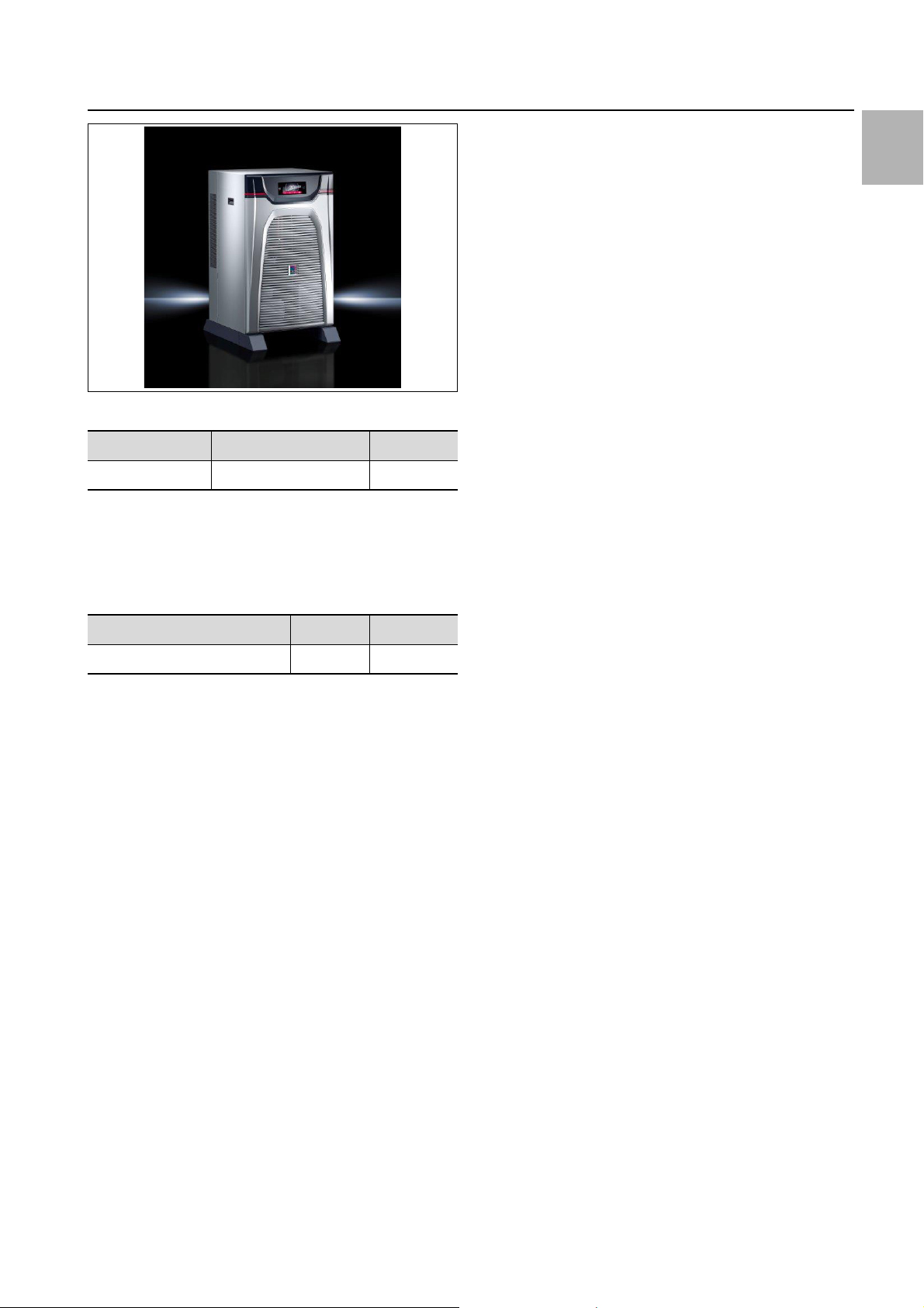
Fig. 38: Cross member
Height [mm] For enclosure depth Model No.
70 600/800 8601680
Tab. 45: Cross member
11.9 External temperature sensor
If the medium temperature needs to be controlled depending on the ambient temperature (positive or negative), differential-based control is used.
11 Accessories
EN
Connection length Packs of Model No.
2.5 m 1 3124400
Tab. 46: External temperature sensor
Rittal Chiller Blue e+ 39
Page 40

EN
A1
Inverter
A2
I/O Board
Q0
G1
X1
BUS 2
M1
M
M1
F2/F3
F2
Y1
Y1
M
M2
M2/M4
PS X7
K1
M
M3
HT
Optional
X6
K2
X10
A3
Control
Display
X13
X4
X14 X14 X14X14
NTC 7 NTC 8
X2 X2
X11
NTC 1 NTC 2 NTC 3 NTC 4 NTC 5 NTC 6
X3 X3 X3 X3 X3 X3 X18
FL LE
X1 X4 X16.3
M5
Optional
Q1
12 Appendix
12 Appendix
12.1 Block diagram
Fig. 39: Block diagram
Key
A1 Inverter
A2 I/O Board
A3 Control Display
F2/F3 High Pressure Switch
FL Flow Sensor
G1 AC In
HT Heater
K1 Contactor
K2 Contactor
LE Water Level Switch
M1 Compressor
M2 Condenser Fan
M3 Pump
M5 Freecooling Valve
NTC1 Water Outlet Temperature
NTC2 Water Inlet Temperature
NTC3 Condensation Temperature
NTC4 Evaporation Temperature
NTC5 Compressor Suction Temperature
NTC6 Ambient Temperature
NTC7 External Sensors
NTC8 External Sensors
Q0 Main switch
Q1 Motor protection switch
X1 Power Supply
X2 Alarm relay 1/2/remote on off
X4 RJ45 BMS Input
X14 Customer interface
Y1 Electronic Expansion Valve
40 Rittal Chiller Blue e+
Page 41
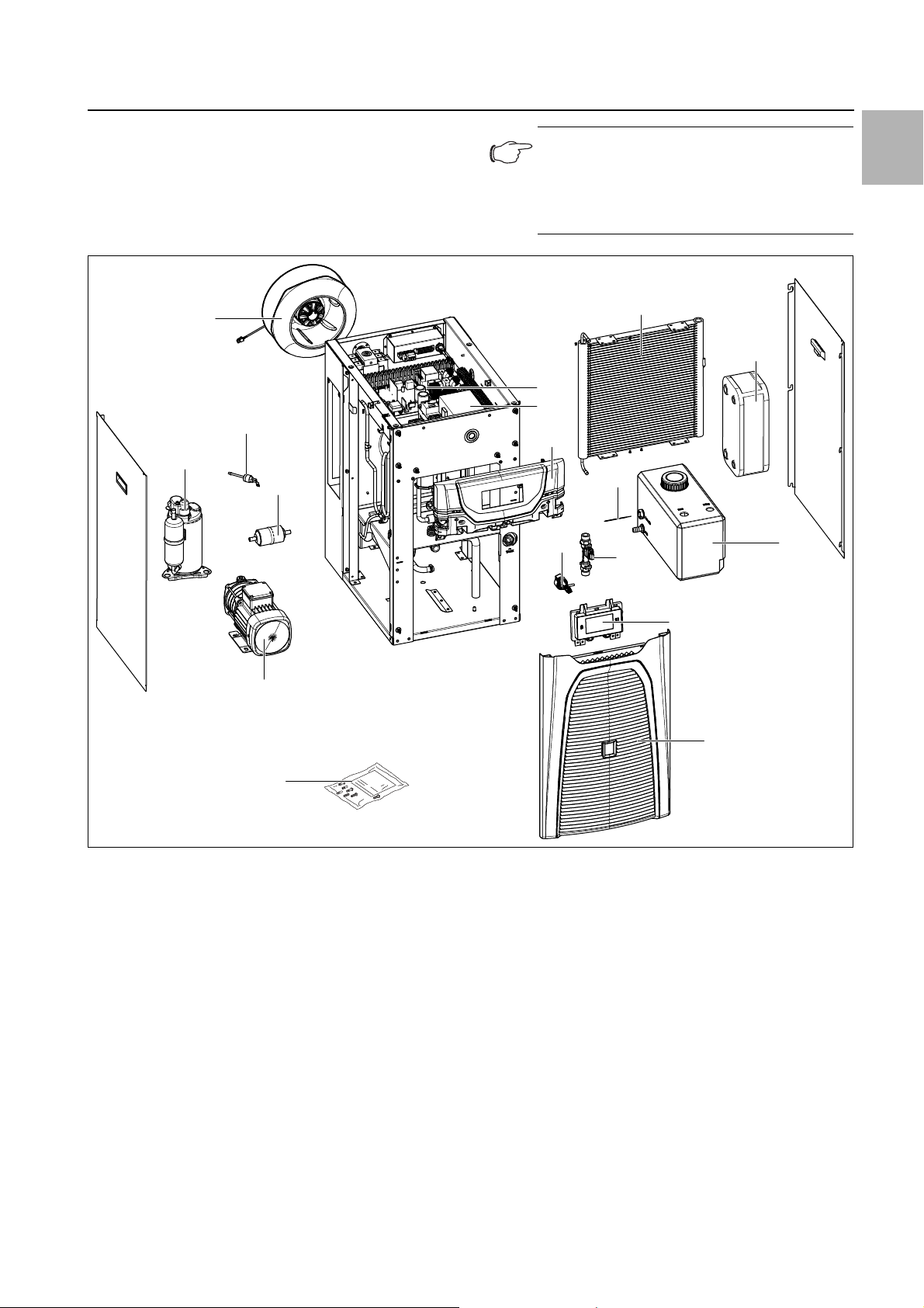
12 Appendix
12.2 Spare parts
Spare parts may be ordered directly from the Rittal website.
– http://www.rittal.com/com_en/spare_parts
Select the Model Number of your chiller here, then
click on "Show spare parts".
5
30
1
25
Note:
The components used are Rittal-specific
components. We recommend using only
original Rittal spare parts to ensure the guaranteed unit properties (output).
100
92
40
41
50
75
20
72
96
EN
6
15
Fig. 40: Spare parts drawing
Key
1 Compressor
5 Radial fan
6 Cooling medium pump
15 Accessories bag
20 Expansion valve
25 Dryer
30 HD switch
40 Inverter
41 I/O board
45 Grille
50 Cover
55 Display
70 Temperature sensor (not illustrated)
71 Temperature sensor (not illustrated)
72 Flow sensor
75 Level switch
92 Plate heat exchanger
55
45
96 Tank
100 Condenser
102 Display cable (not illustrated)
Rittal Chiller Blue e+ 41
Page 42
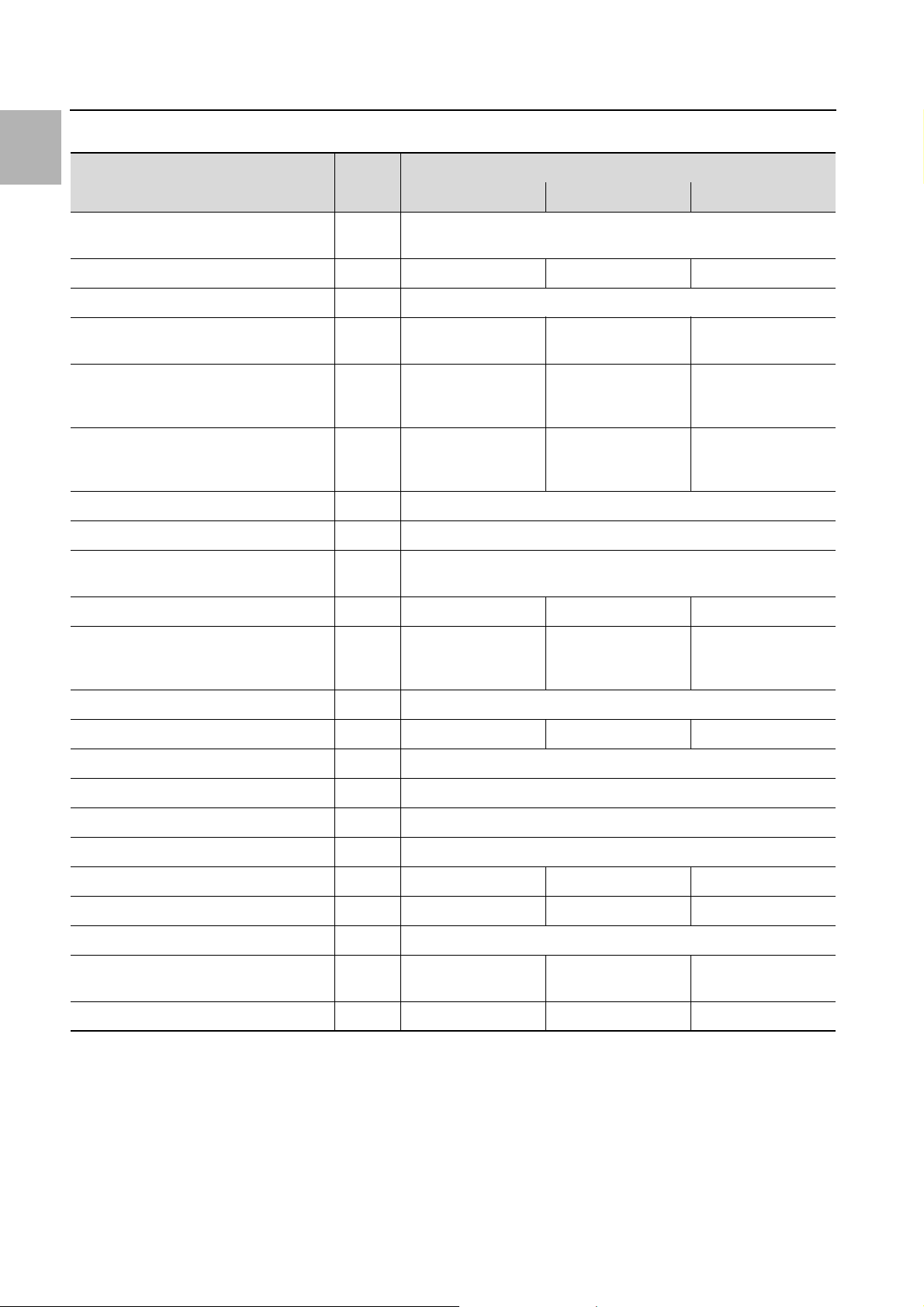
EN
12 Appendix
12.3 Technical specifications
Designation Unit Model No.
3320200 3334300 3334400
Rated voltage/Rated frequency V/Hz
Rated output 50 Hz/60 Hz kW 1.38/1.57 2.49/2.72 2.49/2.72
Minimum circuit ampacity A 15
Input ampere range A
Total cooling capacity at Tw = 18°C,
Tu = 35°C, 50 Hz/60 Hz
(to DIN EN 14511)
EER at T
50 Hz/60 Hz (excluding power consumption of pump)
Rating of overcurrent protective device* A 15
Operating temperature range °C -5…+50
Operating temperature range of cooling
medium
Sound power level Lp dB (A) 74 75 75
Refrigerant
– Identification
–Charge
= 18°C, Tu = 35°C,
w
kW 2.5/2.4 4.0/3.9 5.5/5.4
kW 2.41/2.08 2.8/2.36 2.57/2.26
°C +5…+35
–
g
2.17 A @ 380 V
1.95 A @ 480 V
R134a
460
380…415, 3~, 50
440…480, 3~, 60
3.95 A @ 380 V
3.47 A @ 480 V
R134a
760
3.97 A @ 380 V
3.47 A @ 480 V
R134a
930
GWP – 1430
CO
e t 0.66 1.09 1.33
2
Permissible pressure, cooling circuit (PS) MPa
Permissible pressure, fluid circuit (PS) MPa 0.0 (open circuit)
IP Code IP 24
Tank volume l 12
Flow rate l/min. 7 15 15
Fluid pressure range, 50 Hz/60 Hz bar 1.6…2.5/2.3…3.6 1.9…3.3/2.7…4.9 1.9…3.3/2.7…4.9
Water connections 2 x ¾" internal thread
Power consumption of cooling medium
pump, 50 Hz/60 Hz
Weight kg 84 90 96
Tab. 47: Technical specifications
kW 0.25/0.43 0.43/0.74 0.43/0.74
2.5 LP 1.6
HP
* Time delay fuse type CCMR 15 A or UL listed circuit breaker (DIVQ/7) of type:
– 3RV2711-4AD10 by SIEMENS (E235044) rated 15 A,
– FAZ-C15/3-NA by EATON (E235139) Class curve C rated 15 A,
– FAZ-D15/3-NA by EATON Class curve D rated 15 A
42 Rittal Chiller Blue e+
Page 43

12.4 Device drawings
12 Appendix
EN
Fig. 41: 3320200
Rittal Chiller Blue e+ 43
Page 44

EN
12 Appendix
Fig. 42: 3334300
44 Rittal Chiller Blue e+
Page 45
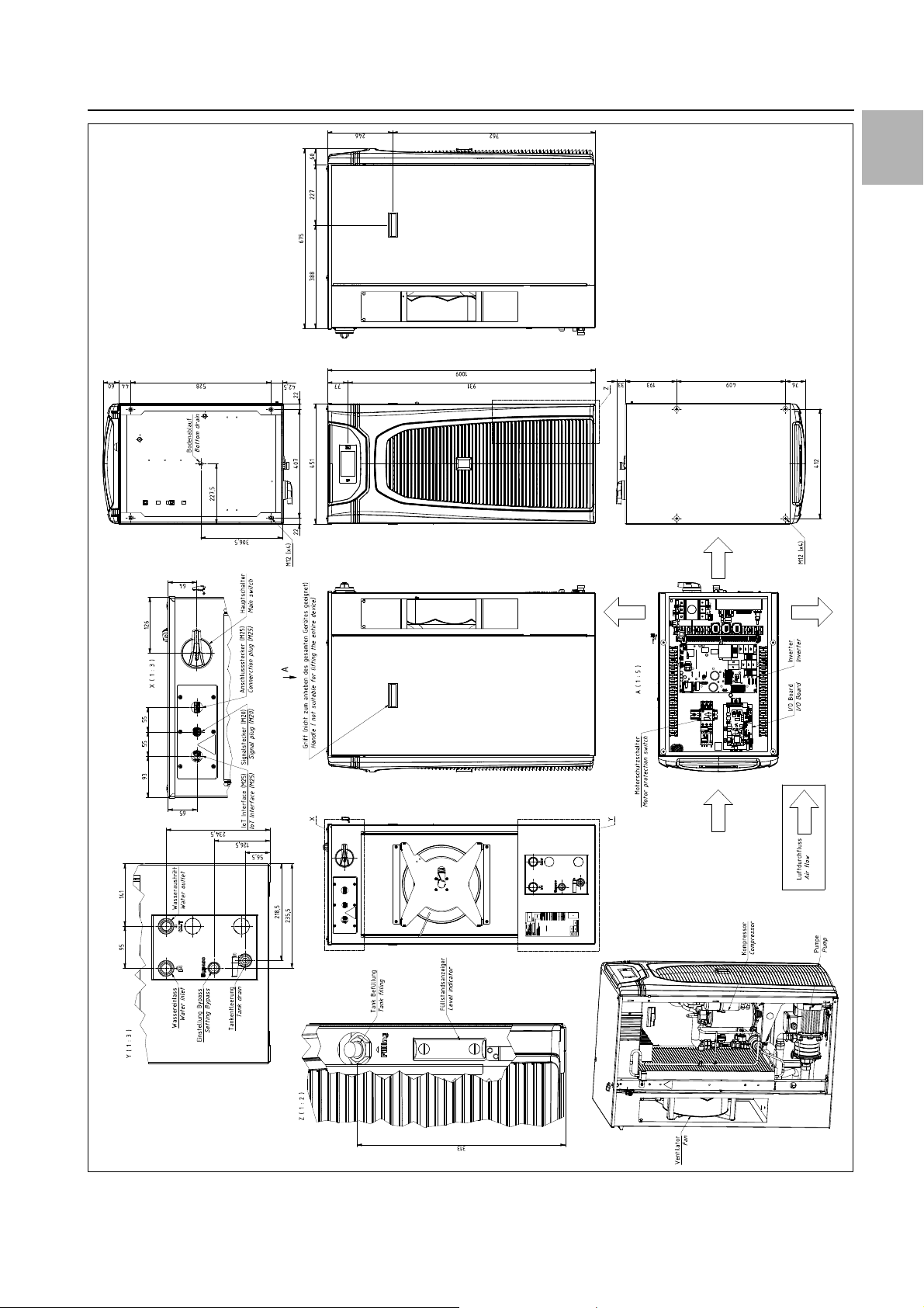
12 Appendix
EN
Fig. 43: 3334400
Rittal Chiller Blue e+ 45
Page 46
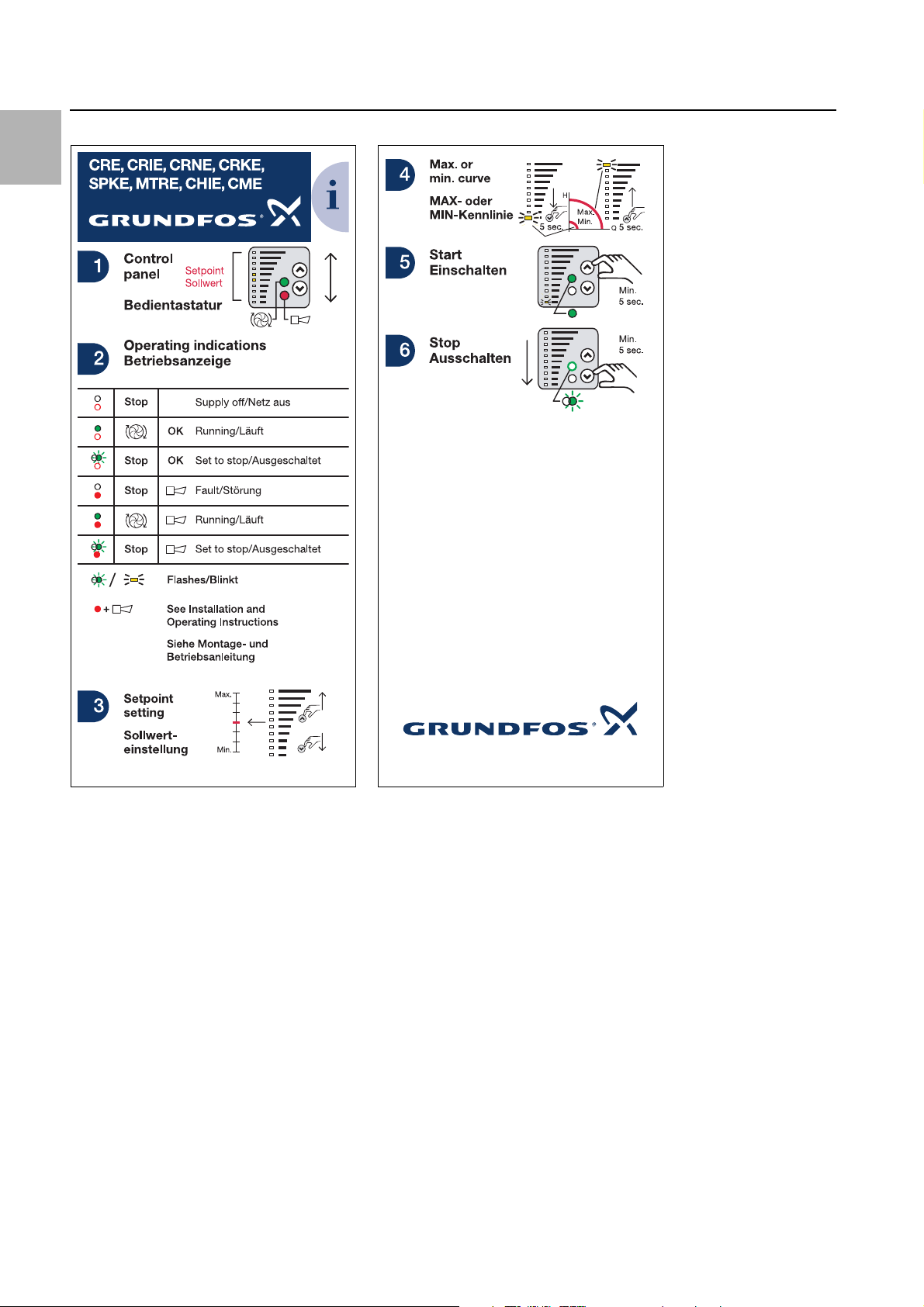
EN
96405681 0608
12 Appendix
12.5 Operation of inverter pump
46 Rittal Chiller Blue e+
Page 47
12 Appendix
Vereinfachte EU-Konformitätserklärung /
Simplified EU Declaration of Conformity
Seite 1 von 1
Wir, / We,
Rittal GmbH & Co. KG y
y Auf dem Stützelberg y 35745 Herborn
Erklären, dass die Produkte / declare that the products
Flüssigkeitskühlsatz Blue e+ Chiller
Blue e+ chiller for cooling media
SK 3320200, SK 3334300, SK 3334400
folgenden Richtlinien entsprechen:
conform to the following directives:
Maschinenrichtlinie 2006/42/EG - Machinery Directive 2006/42/EC
EMV-Richtlinie 2014/30/EU - EMC Directive 2014/30/EU
Bei einer nicht mit uns abgestimmten Änderung des Produkts verliert diese EU-Konformitätserklärung
ihre Gültigkeit. In case of any amendments to the assembly not explicitly agreed with us, this EU
declaration of conformity shall be invalidated.
Die vollständige und unterschriebene EU-Konformitätserklärung erhalten Sie auf der Produktseite der
Rittal Homepage www.rittal.com. The complete and signed declaration of conformity can be obtained
from the product site of the Rittal homepage www.rittal.com
12.6 Declaration of Conformity
EN
Rittal Chiller Blue e+ 47
Page 48
◾Enclosures
◾ Power Distribution
◾ Climate Control
◾ IT Infrastructure
◾ Software & Services
You can find the contact details of all
Rittal companies throughout the world here.
www.rittal.com/contact
RITTAL GmbH & Co. KG
Postfach 1662 · D-35726 Herborn
Phone +49(0)2772 505-0 · Fax +49(0)2772 505-2319
E-mail: info@rittal.de · www.rittal.com
1st edition 02.2018 / ID no. 338311 / Doc. no. D-0000-00001358-00
 Loading...