

Page 1
LCUDX
Assembly and operating instructions
3311.490
3311.491
3311.492
3311.493
Page 2

Foreword
EN
2 Rittal LCU DX
Foreword
Dear Customer,
Thank you for choosing a Rittal Liquid Cooling Unit DX
(also referred to hereafter as "LCU DX").
This documentation applies to the following devices in
the LCU DX series (DX = Direct Expansion):
– LCU DX 3 kW single
–LCU DX 3 kW redundant
– LCU DX 6.5 kW single
– LCU DX 6.5 kW redundant
Those sections where information only applies to one of
the units are labelled accordingly in the documentation.
Please take the time to read this documentation carefully
and pay particular attention to the safety instructions in
the text and to section 2 "Safety instructions".
This is the prerequisite for:
– secure assembly of the LCU DX
– safe handling and
– the most trouble-free operation possible.
Please keep the complete documentation readily available so that it is always on hand when needed.
We wish you every success!
Your,
Rittal GmbH & Co. KG
Rittal GmbH & Co. KG
Auf dem Stützelberg
35745 Herborn
Germany
Tel.: +49(0)2772 505-0
Fax: +49(0)2772 505-2319
E-mail: info@rittal.de
www.rimatrix5.com
www.rimatrix5.de
We are always happy to answer any technical questions
regarding our entire range of products.
Page 3

Rittal LCU DX 3
Contents
EN
Contents
1 Notes on documentation .................. 4
1.1 CE label ........................................................ 4
1.2 Information on electromagnetic compatibility . 4
1.3 Storing the documents .................................. 4
1.4 Symbols in these operating instructions ........ 4
1.5 Associated documents ................................. 4
1.6 Normative instructions .................................. 4
1.6.1 Legal information concerning the operating
instructions ...........................................................4
1.6.2 Copyright ............................................................. 4
1.6.3 Revision ................................................................ 4
2 Safety instructions ............................ 5
2.1 Important safety instructions: ........................ 5
2.2 Service and technical staff ............................ 6
2.2.1 Personal safety equipment ................................... 6
2.3 Operator requirements .................................. 6
2.3.1 Abbreviated instructions ....................................... 6
2.3.2 System log ........................................................... 6
2.3.3 F-gas regulation ................................................... 7
2.3.4 Chemicals – Climate Protection Ordinance ........... 7
2.4 RoHS compliance ......................................... 7
3 Device description ............................ 8
3.1 General functional description ....................... 8
3.2 Air routing ..................................................... 8
3.3 Device assembly ........................................... 8
3.3.1 Internal unit (evaporator coil) ................................. 8
3.3.2 External unit (inverter-controlled cooling unit) ........ 9
3.3.3 Refrigerant lines and electrical pilot wires .............. 9
3.4 Proper and improper usage .......................... 9
3.5 Scope of supply for the LCU DX ................. 10
4 Transport and handling .................. 11
4.1 Transport .................................................... 11
4.2 Unpacking .................................................. 11
5 Assembly and siting ....................... 12
5.1 General ....................................................... 12
5.1.1 Siting location requirements ................................ 12
5.1.2 Relative positioning of the internal unit to the
external unit ........................................................ 12
5.1.3 Supply connections required at the installation
site .....................................................................12
5.1.4 Electromagnetic interference .............................. 12
5.2 Assembly procedure ................................... 12
5.2.1 Preparatory tasks ............................................... 12
5.2.2 Mounting the internal unit ................................... 13
5.2.3 Mounting the internal unit accessories ................ 13
5.2.4 Mounting the external unit .................................. 14
6 Installation ...................................... 16
6.1 General information ..................................... 16
6.2 Notes on pipework ...................................... 16
6.3 Connecting the condensate discharge ........ 18
6.4 Electrical connection ................................... 18
6.4.1 General .............................................................. 18
6.4.2 Connecting the external unit ............................... 19
6.4.3 Connecting the internal unit ................................ 19
6.5 Checking the entire system prior to
commissioning ........................................... 19
6.6 Installing the server .................................... 20
7 Operation ....................................... 22
7.1 Control and display devices ....................... 22
7.2 Switching the LCU DX on and off ............... 22
7.2.1 Switching on the internal and external units ........ 22
7.2.2 Switching off the internal and external units ........ 22
7.2.3 Switching off in an emergency ............................ 22
7.3 Setting the setpoint temperature ................ 22
8 Troubleshooting ............................. 24
8.1 General ...................................................... 24
8.2 List of error messages ................................ 24
9 Inspection and maintenance ........... 25
10 Storage and disposal ...................... 26
11 Technical specifications .................. 27
11.1 LCU DX 3 kW ............................................. 27
11.2 LCU DX 6.5kW ........................................... 28
11.3 Information about the refrigerant ................ 29
11.4 Cooling output ........................................... 29
11.4.1 LCU DX 3 kW ..................................................... 30
11.4.2 LCU DX 6.5 kW .................................................. 31
11.5 Overview drawings ..................................... 32
11.5.1 Internal unit LCU DX 3 kW and 6.5 kW ............... 32
11.5.2 Dimensions of internal unit LCU DX 3 kW and
6.5 kW ............................................................... 33
11.6 RI flow chart LCU DX ................................. 34
11.7 Circuit diagram ........................................... 35
11.7.1 Functional diagram, internal unit ......................... 35
11.7.2 Connection internal unit – external unit, external
interfaces ........................................................... 36
11.7.3 Circuit diagram, external unit .............................. 37
12 Spare parts .................................... 38
13 Accessories .................................... 39
14 Glossary ......................................... 40
15 Customer service addresses .......... 41
Page 4
1 Notes on documentation
EN
4 Rittal LCU DX
1 Notes on documentation
1.1 CE label
The declaration of conformity has been issued by the
company Hannich GmbH and is included with the supply of the LCU DX.
The cooling unit bears the following mark:
1.2 Information on electromagnetic compatibility
The LCU DX is a class A device as defined by EN 55022.
Under certain circumstances, the device may cause radio interference in domestic environments. In such cases, the operator may be asked to implement appropriate
measures.
1.3 Storing the documents
The assembly and operating instructions as well as all
other applicable documents are an integral part of the
product. They must be passed to those persons who
are engaged with the unit and must always be available
and on hand for the operating and maintenance personnel.
1.4 Symbols in these operating instructions
The following symbols are used in this documentation:
This symbol indicates an "Action Point" and shows
that you should perform an operation/procedure.
1.5 Associated documents
The general plant documentation for the room where the
equipment is situated (construction specifications for the
ventilation system) also applies in conjunction with these
assembly and operating instructions.
1.6 Normative instructions
1.6.1 Legal information concerning the operating
instructions
We reserve the right to make changes in content. Rittal
GmbH & Co. KG and/or Hannich GmbH are not responsible for any damage which may result from failure to
comply with these assembly and operating instructions.
The same applies to failure to comply with the valid documentation for any accessories used.
1.6.2 Copyright
The distribution and duplication of this document and
the disclosure and use of its contents are prohibited unless expressly authorised.
Offenders will be liable for damages. All rights created by
a patent grant or registration of a utility model or design
are reserved.
1.6.3 Revision
Rev. 0A of 25/01/2016
Danger!
Hazardous situation which will result in
death or serious injury if the instructions
are not followed.
Warning!
Hazardous situation which may lead to
death or serious injury if the instructions
are not followed.
Caution!
Hazardous situation which may lead to
(minor) injuries if the instructions are not
followed.
Note:
Information concerning individual procedures, explanations, or tips for simplified approaches. Also indicates situations which
may result in material damage.
Page 5

Rittal LCU DX 5
2 Safety instructions
EN
2 Safety instructions
The devices in the LCU DX series from Rittal GmbH &
Co. KG are developed and manufactured with due regard for all safety precautions. Nevertheless, the unit still
poses a number of unavoidable dangers and residual
risks. These safety instructions provide an overview of
these dangers and the necessary safety precautions.
In the interests of your own safety and the safety of others, please read these safety instructions carefully before assembling and commissioning the LCU DX!
Follow the user information found in these instructions
and on the unit carefully.
2.1 Important safety instructions:
Danger! Electric shock!
Contact with live electrical parts may result in fatal injury.
Before switching on, ensure that there is
no possibility of accidental contact with
live electrical parts.
The unit has a high discharge current.
Before connecting to the supply circuit,
therefore, it is essential to make a 6 mm²
earth connection (see section 11.7 "Circuit diagram").
Danger! Injury caused by fan impellers.
Keep persons and objects away from
the fan impellers. Do not remove covers
until the power supply is disconnected
and impellers are immobilised. Always
use mechanical protection when working. Shut down the respective fan during
maintenance work, if possible. Tie long
hair back. Do not wear loose clothing.
The fans will start up again automatically
following a power disruption.
Danger! Hot components may cause injury!
The external unit and the pipelines are
hot during operation, and may cause
burns on direct contact.
Danger! Risk of poisoning from refrigerant gases created under the influence of
heat.
When carrying out welding and soldering work, shortness of breath or asphyxiation may occur.
The refrigerant is heavier than air, and in
high concentrations may cause shortness of breath and asphyxiation, by displacing the oxygen.
Danger! Risk of poisoning from refrigerant gases created under the influence of
heat.
When carrying out welding and soldering work on the refrigerant circuit, use
protective gloves and breathing apparatus with a filter.
Even a very low concentration of refrigerant may cause the refrigerant to decompose in combination with a naked
flame, and cause acute shortness of
breath.
Danger! Risk of injury from incorrect installation.
Installation of the refrigerant lines and
other media connections must only be
carried out by qualified plumbers or
cooling technology specialists.
Danger! Threat to the environment from
escaping refrigerant!
Never allow the refrigerant to escape
into the environment if at all possible
(see section 2.3.3 "F-gas regulation").
Danger! Injury due to falling loads!
Do not stand under suspended loads
when transporting the unit with a hoist
trolley, a forklift, or a crane.
Warning! Danger of cut injuries, especially from the sharp edges of the fan
module and heat exchanger module.
Put on protective gloves before beginning assembly or cleaning work.
Page 6
2 Safety instructions
EN
6 Rittal LCU DX
As a general requirement, please observe the following
five safety rules to DIN EN 50110-1 (VDE 0105-1) when
working in and on the LCU DX, in order to avoid accidents:
1. Switch off!
Switch off the on-site power supply to the LCU DX.
2. Secure against reactivation.
3. Ensure that all poles are de-energised.
4. Earth and short-circuit.
5. Cover or shield adjacent, live parts.
2.2 Service and technical staff
The installation, commissioning, maintenance and repair
of this unit may only be carried out by trained, qualified
mechanical, electro-technical and refrigeration engineering specialists.
Only properly instructed personnel may service a unit
while in operation.
2.2.1 Personal safety equipment
Personal safety equipment, which should as a minimum
include thermally insulated gloves and protective goggles, is to be worn during any work on this unit when
personnel might come into contact with refrigerant (see
section 11.3 "Information about the refrigerant").
Additionally, in the event of fire, airtight respiratory
masks must be worn.
2.3 Operator requirements
In accordance with EU Regulation 842/2006, for a total
refrigerant fill volume of more than 2.5 kg (R410A), the
operator must carry out a leak test at least once a year.
This fill volume is achieved or exceeded with a pipe
length of > 28 m.
Any leaks that are detected must be repaired immediately.
2.3.1 Abbreviated instructions
The operator must ensure that abbreviated instructions
containing the following information are available in a
readily accessible location on the LCU DX:
1. Name, address and telephone number of the installation company, its customer service department, or
the customer service department of the owner/operator, or as a minimum requirement, the individual
responsible for the cooling system, together with the
address and telephone number of the fire brigade,
police, hospitals and burn victims centres.
2. Type of refrigerant: R410A, comprising 50% difluoromethane R32 (CH
2F2
) and 50% R125 penta-
fluoroethane (C
2HF5
);
3. Instructions for switching off the cooling system in
an emergency (see section 7.2.3 "Switching off in an
emergency");
4. The maximum permissible pressures (see section11 "Technical specifications").
2.3.2 System log
Under DIN EN 378, the operator is required to keep a
system log and ensure that it is regularly updated. The
system log should contain the following information:
1. Details of all repair work
2. Quantity and type (new, reused or recycled) of refrigerant added, quantity of refrigerant removed
Warning! Injuries from escaping refrigerant.
Escaping gas may freeze the skin. Before working on the cooling circuit, put
on protective gloves and goggles.
Caution! Risk of malfunction or damage!
Do not modify the unit. Use only original
spare parts.
Caution! Risk of malfunction or damage!
Proper operation can only be ensured if
the unit is operated under the intended
ambient conditions. As far as possible,
observe the ambient conditions for
which the unit was designed, e.g. temperature, humidity, air purity.
Caution! Risk of malfunction or damage!
All media required for the control system, such as the correct fill volume of refrigerant, must be available throughout
the entire operating period of the device.
Caution! Risk of malfunction or damage!
Installation, and in particular the laying
of the refrigerant pipework between the
internal and external unit, must only be
carried out by trained, qualified and accredited cooling system specialists.
Caution! Risk of malfunction or damage!
In order to prevent EMC-related malfunctions during operation, and to allow
access for servicing purposes, crosswiring through the LCU DX to the bayed
racks is prohibited.
Note:
Rittal offers leak testing of the device as a
service.
Page 7

Rittal LCU DX 7
2 Safety instructions
EN
3. Outcome of any analysis of reused refrigerant, if
available
4. Origin of reused refrigerant
5. Amendments to and replacement of system components
6. Results of all regular routine checks and
7. Any significant shutdowns
2.3.3 F-gas regulation
Regulation (EC) No. 842/2006 of the European Parliament and of the Council of 17 May 2006 on certain fluorinated greenhouse gases entered into force on 4 July
2006. The Regulation regulates the reduction of emis-
sions, the use, recovery and destruction of certain fluorinated greenhouse gases, and the labelling and disposal
of products and equipment containing such gases.
Leak test pursuant to Article 3 (containment)
– 3kg – 30kg at 12-month intervals (or 6 kg in hermet-
ically sealed systems),
– 30 kg – 300 kg at 6-month intervals,
– more than 300 kg at 3-month intervals.
2.3.4 Chemicals – Climate Protection Ordinance
This Ordinance applies in addition to the aforementioned
Regulation (EC) No. 842/2006 of the European Parliament and of the Council of 17 May 2006 on certain fluorinated greenhouse gases.
2.4 RoHS compliance
The LCU DX fulfils the requirements of EU Directive
2011/65/EC on the Restriction of Use of Certain Hazardous Substances in Electrical and Electronic Equipment
(RoHS) of 8 June 2011.
Note:
Corresponding information about the RoHS
Directive may be found on our website at
www.rittal.com/RoHS.
Page 8
3 Device description
EN
8 Rittal LCU DX
3 Device description
3.1 General functional description
The Liquid Cooling Unit DX (DX = Direct Expansion) is
essentially a split cooling unit used to dissipate heat
losses from server enclosures or for the effective cooling
of devices built into a server enclosure.
The air routing in the LCP DX supports the "front to
back" cooling principle of the devices built into the server
enclosure. The hot air expelled by the devices in the
server enclosure is drawn in by the fans at the rear directly from the server enclosure or Micro Data Center
and then routed through the heat exchanger module.
In the heat exchanger module, the heated air is directed
through a heat exchanger (refrigerant evaporator), and
its thermal energy (heat loss from the server enclosure)
is removed from the refrigerant via evaporation. This process cools the air to a freely selectable temperature, and
it is then routed directly in front of the 482.6 mm (19")
level in the server enclosure or Micro Data Center.
The setpoint (outlet temperature from the cooling unit or
server air intake temperature) may be set in the range
+18°C to +28°C.
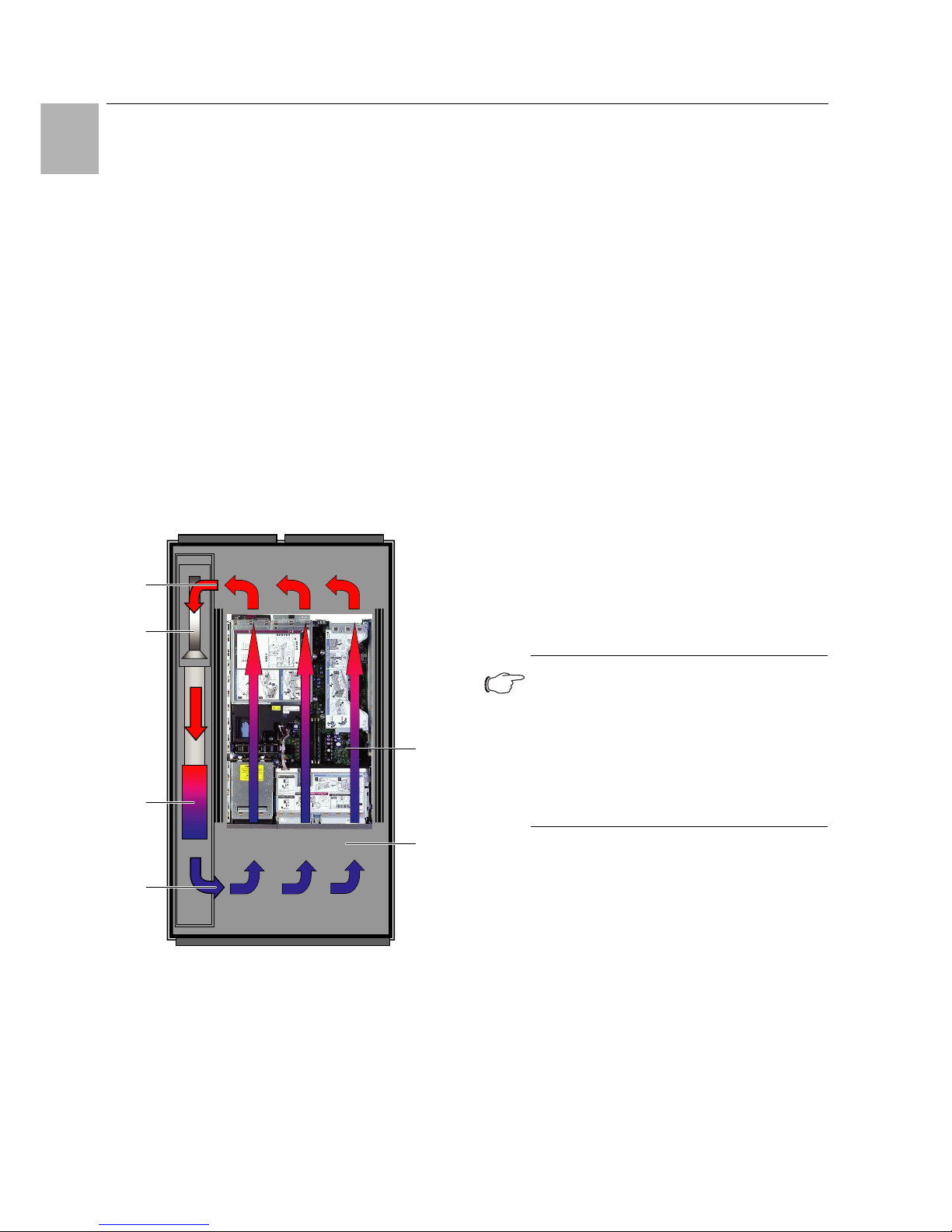
Fig. 1: Air routing on the LCU DX – Top view
Key
1 Installed equipment in the server
2 Server enclosure/Micro Data Center
3Air outlet
4 Heat exchanger
5Fan
6 Air inlet
In the LCU DX, the temperature of the incoming cold air
(server air intake) is controlled by continuously compar-
ing the actual temperature with the setpoint temperature
(preset to +22°C).
If the actual temperature exceeds the setpoint temperature, the speed of the compressor is automatically increased, providing a greater cooling output from the
heat exchanger, until the setpoint temperature is
reached.
In the LCU DX, the measured temperature of the extracted warm air is used to determine and control the required fan speed.
Any condensate incurred is collected in the integral condensate collecting tray below the heat exchanger, and
from there is routed outside via a condensate discharge
hose.
3.2 Air routing
In order to achieve sufficient cooling in the server enclosure, it is important to ensure that the cooling air passes
through the interior of the built-in devices rather than
flowing past at the sides.
Targeted air routing inside the server enclosure has a
major effect on the thermal output to be dissipated.
In order to ensure targeted air routing in the system, the
server enclosure should be divided vertically into warm
air and cold air sections. Essentially, this is already ensured by the 482.6 mm (19") arrangement and the installation of "front to back" vented servers. Consistent
sub-division is achieved with additional plastic foam
strips and air baffle plates on the left and right of the
482.6 mm (19") level (see section 13 "Accessories").
If the LCU DX is used to cool a TS IT server enclosure, it
is important that this is sealed, by fitting the enclosure
with side panels, roof and gland plates. Any existing cable entries should be sealed e.g. using suitable brush
strips. Whilst the system is in operation, both the front
and the rear doors should be kept completely shut. No
slotted doors should be used.
When using in the Micro Data Center, the LCU DX is inserted in a sealed safe structure for application-related
reasons.
3.3 Device assembly
3.3.1 Internal unit (evaporator coil)
The internal unit of the LCU DX may be bayed either on
the right or left of a server enclosure or Micro Data
Center. To this end, the internal unit is mounted directly
5
4
3
6
1
2
Note:
The 482.6 mm (19") level must likewise be
completely sealed. This is already the case in
a fully configured server enclosure. With a
partially configured server enclosure, the
open height units (U) of the 482.6 mm (19")
level must be sealed with blanking plates,
which are available as Rittal accessories (see
section 13 "Accessories").
Page 9

Rittal LCU DX 9
3 Device description
EN
on fixing brackets on the rear wall of the evaporator coil.
The evaporator coil has two condensate collecting trays
to enable installation on the left or right of the enclosure.
The bottom condensate discharge in each case remains
unused.
The internal unit is comprised of the following components:
– Housing of powder-coated sheet steel.
– Two condensate collecting trays in the enclosure (bot-
tom/top) so that the evaporator coil can be used in
two installation positions. The discharge connection of
the condensate tray has a diameter of 12 mm.
– Direct refrigerant evaporator coil of inner-grooved
copper core pipes with aluminium membranes. The
evaporator coil is pressurised with exhaust air from the
server in order to ensure heat absorption (heat dissi-
pation) via the refrigerant flowing into the copper
pipes.
– Evaporator coil fan as linear controlled EC fan.
– Full electronic control of all components in the internal
unit, for evaporator coil fan speed control, server in-
take air temperature control, and power demand from
the external unit. The controller has temperature sen-
sors built into the intake and exhaust side of the inter-
nal unit, as well as on the evaporator coil itself.
– Additional temperature sensor in the server front.
3.3.2 External unit (inverter-controlled cooling
unit)
The external unit is comprised of the following components:
– Housing of weather-proof, stove-enamelled sheet
steel.
– Compressor for compressing and circulating the re-
frigerant from the low-pressure side (internal unit) to
the high-pressure side (external unit). The motor is ac-
tivated by an external inverter, which controls the
speed of the compressor and therefore allows the
cooling output to be precisely adapted to the actual
cooling requirement.
– Full electronic control of all components and measure-
ment devices on the external unit, including various
sensors and pressure measuring devices.
– Condenser for condensing the compressed refriger-
ant so that it can be returned to the evaporator coil via
the expansion valve in liquid form. The condenser is
comprised of copper core pipes with aluminium mem-
branes and a DC fan motor, which is speed-controlled
to adjust the output.
– Electronic expansion valve to supply the evaporator
coil with the required volume of refrigerant, so as to
ensure the corresponding optimum thermal absorp-
tion capacity to suit the current output requirements.
The expansion valve is electronically regulated via the
pilot wire from the evaporator coil.
3.3.3 Refrigerant lines and electrical pilot wires
The medium connection lines between the internal unit
and the external unit are comprised of the following
components:
– Pair of refrigerant lines as a refrigerant suction line (re-
turn) and refrigerant liquid line (inlet), including condensate insulation. Refrigerator-quality copper pipes
should be cleaned and dried (to DIN EN 12735-1/DIN
1786) and sealed before use.
– Electrical and pilot wire lines between the internal unit
and the external unit in a UV-resistant design.
3.4 Proper and improper usage
The LCU DX is used to dissipate low to medium heat
losses and for the effective cooling of devices built into a
server enclosure/Micro Data Center. The unit is designed solely for static use in sealed rooms.
The unit is state of the art and built according to recognised safety regulations. Nevertheless, improper use
can pose a threat to the life and limb of the user or third
parties, or result in possible damage to the system and
other property.
Consequently, the unit must only be used properly and
in a technically sound condition!
Any malfunctions which impair safety should be rectified
immediately.
Proper usage also includes following the operating instructions and fulfilling the inspection and maintenance
conditions.
Inappropriate use can be dangerous. Examples of inappropriate use include:
– Use of another external unit
– Improper operation
– Use of a refrigerant other than R410A
– Use of a refrigerant fill volume other than that specified
– Installation of the external unit in an unsuitable position
– Improper rectification of malfunctions
– Use of replacement parts which are not authorised by
Rittal GmbH & Co. KG
– Non-static use, e.g. on moving or vibrating machines
Page 10
3 Device description
EN
10 Rittal LCU DX
3.5 Scope of supply for the LCU DX
The supply of an LCU DX in the "single" variant includes
the following:
The supply of an LCU DX in the "redundant" variant includes the following:
Qty. Parts
1
LCU DX
, ready to connect, consisting of:
1 Internal unit
1 Remote control/operating unit
1 Holder for operating unit (482.6 mm (19") con-
sole, 3 U)
1 Temperature sensor, server front
1 Condensate discharge hose with copper si-
phon
1 External unit
1 Set of accessories for mounting the internal
unit and for the air block panel
1 Assembly and operating instructions
Tab. 1: Scope of supply of an LCU DX, "single" variant
Qty. Parts
1
LCU DX
, ready to connect, consisting of:
1 Internal unit
2 Remote control/operating unit
1 Holder for operating unit (482.6 mm (19") con-
sole, 3 U)
2 Temperature sensor, server front
1 Condensate discharge
2 External unit
1 Set of accessories for mounting the internal
unit and for the air block panel
1 Assembly and operating instructions
Tab. 2: Scope of supply of an LCU DX, "redundant" variant
Page 11
Rittal LCU DX 11
4 Transport and handling
EN
4 Transport and handling
4.1 Transport
The LCU DX is delivered shrink-wrapped on a pallet.
4.2 Unpacking
Remove the packaging materials from the unit.
Check the unit for any damage that may have oc-
curred during transport.
Place the unit in its intended location.
Caution!
Because of its height and narrow base,
the LCU DX is liable to tip over. Risk of
toppling, especially after the unit is removed from the pallet!
Caution!
Transportation of the LCU DX without a
pallet:
Use only suitable and technically sound
lifting gear and load-bearing devices
with sufficient load capacity.
Note:
After unpacking, the packaging materials
must be disposed of in an environmentally
friendly way. They consist of the following
materials:
Wood, polyethylene film (PE film), strap, edge
protectors.
Note:
Damage and other faults, e.g. incomplete delivery, should be reported immediately, in
writing, to the shipping company and to Rittal
GmbH & Co. KG.
Page 12
5 Assembly and siting
EN
12 Rittal LCU DX
5 Assembly and siting
5.1 General
5.1.1 Siting location requirements
To ensure proper functioning of the LCU DX, the following conditions for the siting location of the device must
be observed.
Climatic conditions
When choosing a siting location for the internal unit
and external unit, please observe the values prescribed in section 11 "Technical specifications" for the
ambient temperature, dewpoint and air purity.
According to ASHRAE Directive TC 9.9, a maximum
room temperature of 30°C at 50% relative humidity must
be observed at the internal unit's siting location. This
equates to a dew point of 19°C. If these limits are exceeded, there is a risk of condensation forming on the air
outlet of the internal unit.
Floor conditions
– The floor of the installation space should be rigid and
level.
– Choose the location carefully so that the unit is not sit-
uated on a step or uneven surface, etc.
Minimum required thermal output in the enclosure
In order to achieve continuous operation of the LCU DX,
a heat load of at least 1 kW (3 kW version) or 3 kW
(6.5 kW version) respectively must be installed in the enclosure. Otherwise, intermittent operation of the system
may occur.
5.1.2 Relative positioning of the internal unit to
the external unit
The internal unit and the external unit must be connected with a suitable copper pipe connection to DIN EN
378-2. The entire system must then be filled with refrigerant (cf. section 6.2 "Notes on pipework").
The following distances and geodetic height differences
must not be exceeded when installing the internal unit
and external unit:
5.1.3 Supply connections required at the installation site
Power is usually supplied to the external unit.
LCU DX 3 kW
LCU DX 6.5 kW
5.1.4 Electromagnetic interference
– Interfering electrical installations (high frequency) are
to be avoided.
5.2 Assembly procedure
5.2.1 Preparatory tasks
The internal unit may be mounted both on the right and
on the left of the TS IT server enclosure.
Before the internal unit of the LCU DX can be installed in
a TS IT server enclosure, the following work should be
carried out.
Slide the 482.6 mm (19") mounting angles 50 mm
away from you.
Recommendation:
Where necessary, these values should be
achieved by installing an additional room airconditioning system.
Position Distance
Maximum equivalent pipeline
length
LCU DX 3 kW: 30 m
LCU DX 6.5 kW: 50 m
Of which maximum height
difference
12 m
Tab. 3: Distances and height differences
Connection type Connection description
Electrical connection
LCU DX 3 kW
230 V, 1~, N, PE, 50 Hz
Electrical fuse provided by the customer
16 A, miniature circuit-breaker
with C characteristic
Refrigerant connection
Copper pipework
Tab. 4: Supply connections for the LCU DX 3 kW
Connection type Connection description
Electrical connection
LCU DX 6.5 kW
230 V, 1~, N, PE, 50 Hz
Electrical fuse provided by the customer
20 A, miniature circuit-breaker
with C characteristic
Refrigerant connection
Copper pipework
Tab. 5: Supply connections for the LCU DX 6.5 kW
Note:
Installation in a Micro Data Center is described in the assembly instructions for the
Micro Data Center. The assembly parts required for the internal unit are included with
the supply of the Micro Data Center.
Note:
The LCU DX may only be operated in combination with 482.6 mm (19") mounting angles.
Installation with a 482.6 mm (19") mounting
frame is not possible.
Page 13
Rittal LCU DX 13
5 Assembly and siting
EN
Fig. 2: Move the 482.6 mm (19") level sideways
Ensure that the front distance from the 482.6 mm (19")
mounting angle to the front edge of the TS frame is at
least 100 mm.
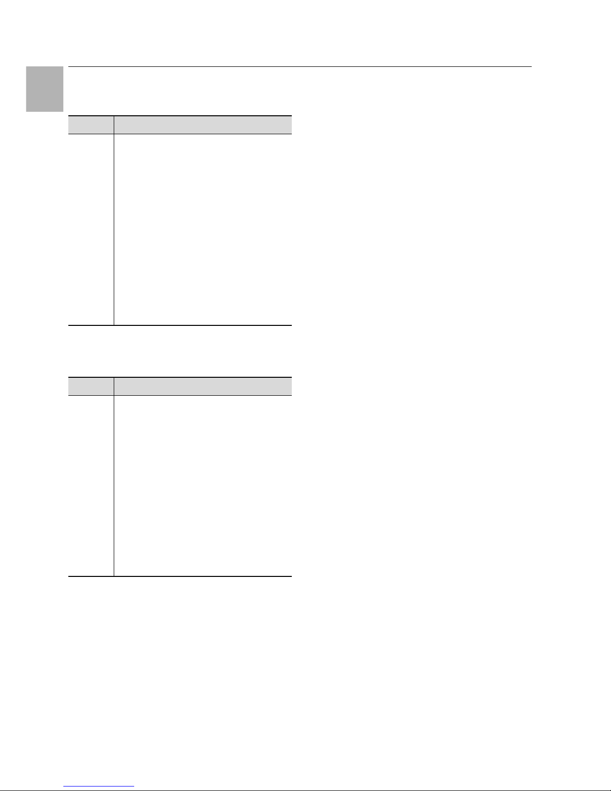
Fig. 3: Move the 482.6 mm (19") level in the depth
Position the punched section with mounting flange as
shown in the assembly drawing (Fig. 18) and attach it
to the inner level of the TS frame (mounting side).
Remember to maintain a distance of at least 15 cm
between the roof plate and the top edge of the internal
unit.
Locate the two mounting devices supplied loose for
installing the internal unit into the lower punched section with mounting flange.
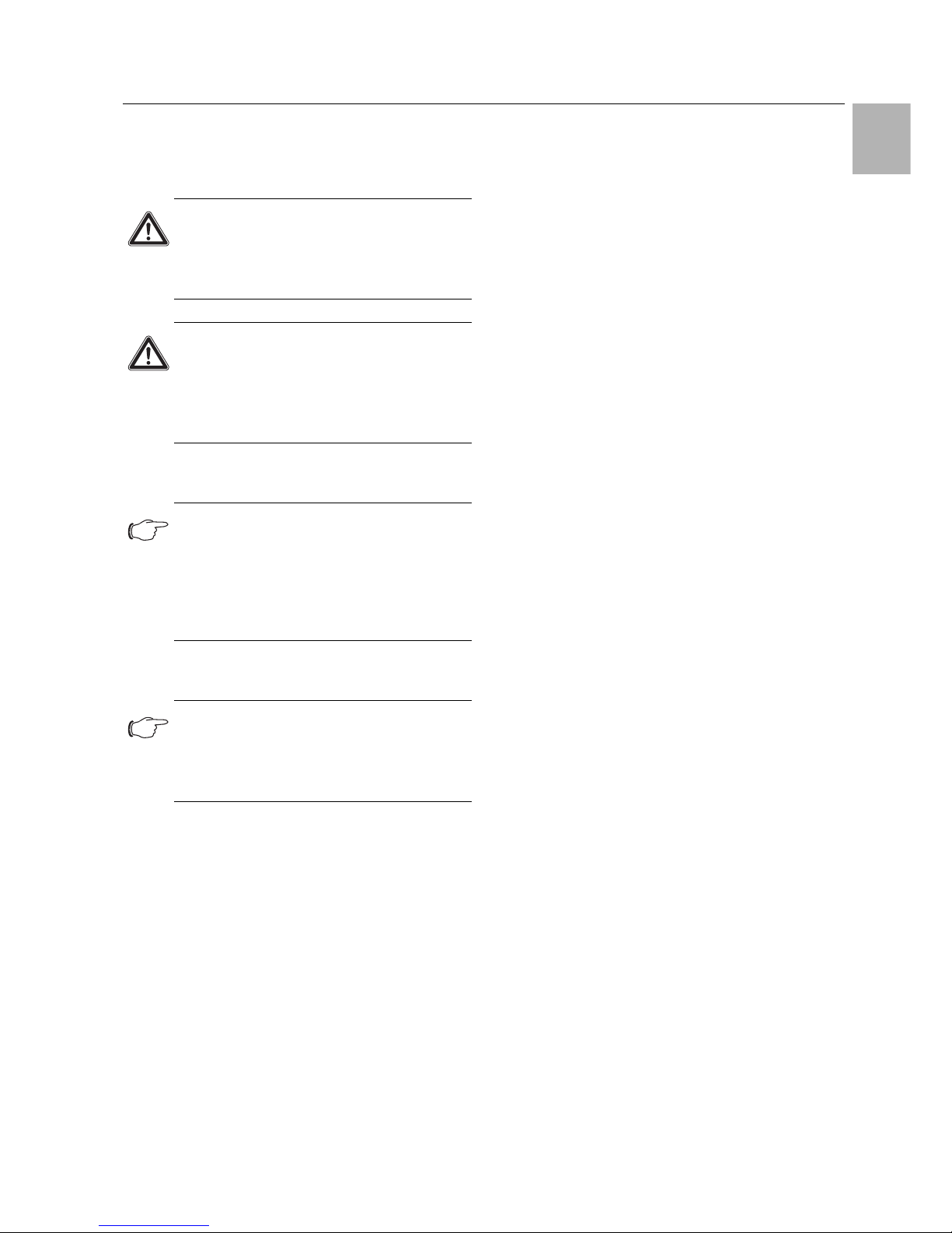
Fig. 4: Arrangement of the internal unit
Key
1 Internal unit
2 Rear wall of internal unit
3 Mounting device
4 Punched section with mounting flange
5 Assembly screw
5.2.2 Mounting the internal unit
Position the internal unit on the mounting devices in
such a way that the air outlet opening is on the operator side of the server enclosure, and the fans are in the
rear section.
The end face of the internal unit must be flush with the
front edge of the TS frame.
Align the internal unit horizontally.
In this position, screw the internal unit to the punched
section with mounting flange using the attachment
points provided (at the top and bottom of the rear panel).
5.2.3 Mounting the internal unit accessories
Install the remote control (3U trim panel) with the builtin operating units at the top of the 482.6 mm (19") level, on the maintenance side of the rack.
Fig. 5: Mounting the internal unit accessories
Key
1 Remote control (3U trim panel)
2 Control and display device 1
3 Control and display device 2
4 Second control and display device 1 for "redundant" ver-
sion
For the "single" version, fit the external temperature
sensor included with the supply in a suitable position
in front of the server installations.
5
4
2
1
3
4
3
1
2
Page 14

5 Assembly and siting
EN
14 Rittal LCU DX
For the "redundant" version, fit the second external
temperature sensor included with the supply, likewise
in a suitable position in front of the server installations.
5.2.4 Mounting the external unit
The external unit may be secured to a solid wall or onto
a flat roof or concrete surface using wall brackets (accessory, not included with the supply).
Please observe the following instructions regarding the
installation site:
– The external unit is weather-resistant and may there-
fore be installed completely in the open air, with no
need for a weather protection canopy etc.
– For continuous operation, the base surface must rise
above the snow zone.
– It is also important to ensure that foreign bodies such
as leaves cannot be drawn into the external unit.
– The external unit must not be exposed to extreme
wind conditions, otherwise the heat exchanger could
be excessively under-cooled, or the fan would need to
work against the wind and be unable to move the required volume of air.
– If necessary, a wind break should be installed at a dis-
tance of 1 m from the device.
– If the unit is installed underneath a canopy, there must
be a distance of at least 2 m between the floor and the
canopy.
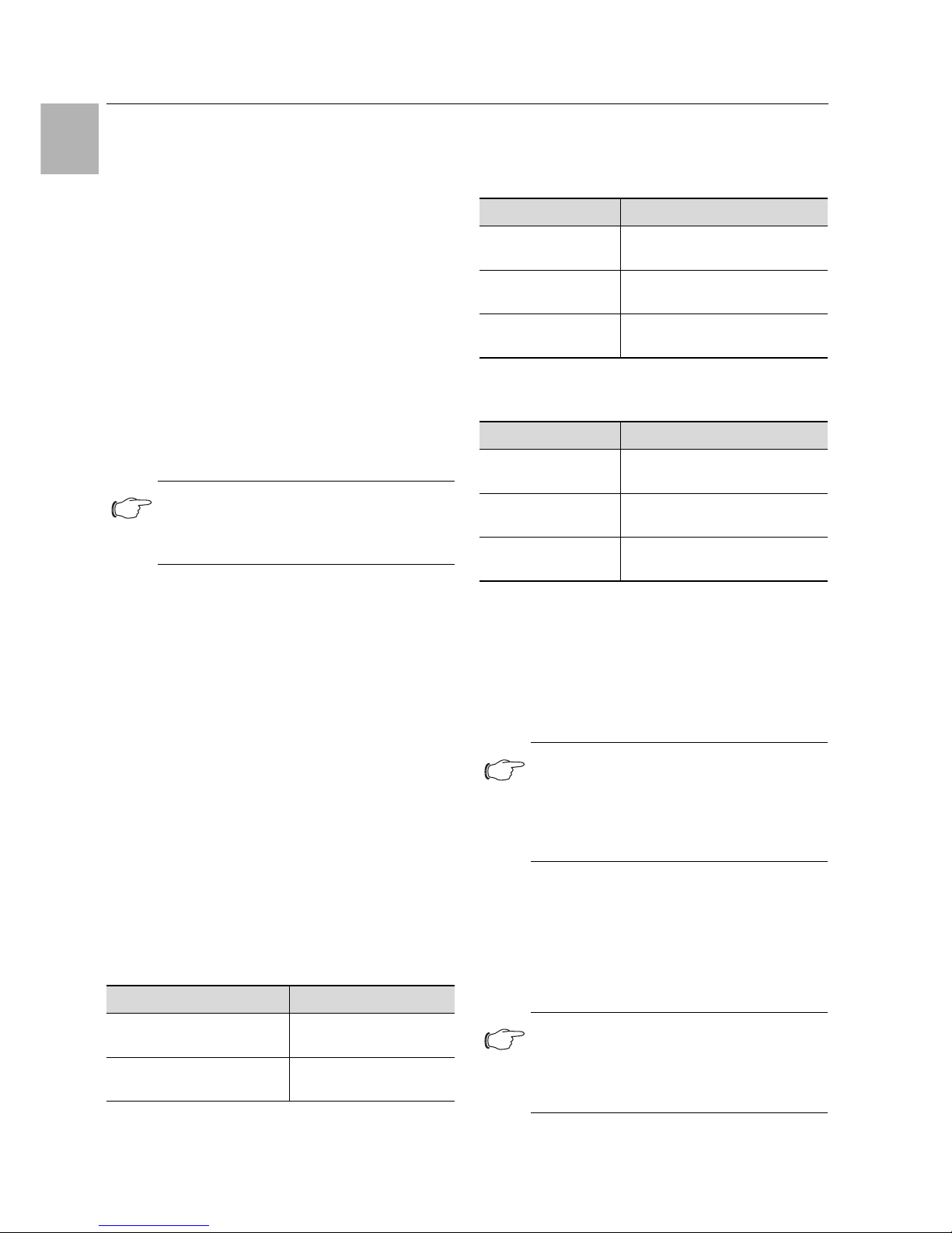
The following distances should be observed for maintenance purposes:
Fig. 6: Distances from external unit
Key
1 Air inlet
2Distance > 300mm
3 Clearance for maintenance: Distance > 600 mm
4Air outlet
5Distance > 200mm
6 External unit
7Distance > 600mm
8 Roof area/foundations
9 Strip foundation
10 Assembly screws/vibration dampers
The installation site of the external unit must be carefully selected to ensure an adequate supply and distribution of the airflow, even in unfavourable conditions.
Install the external unit on brackets, remembering to
observe the required minimum distance from the wall.
Attach the external unit to the base plate to avoid the
risk of tipping over.
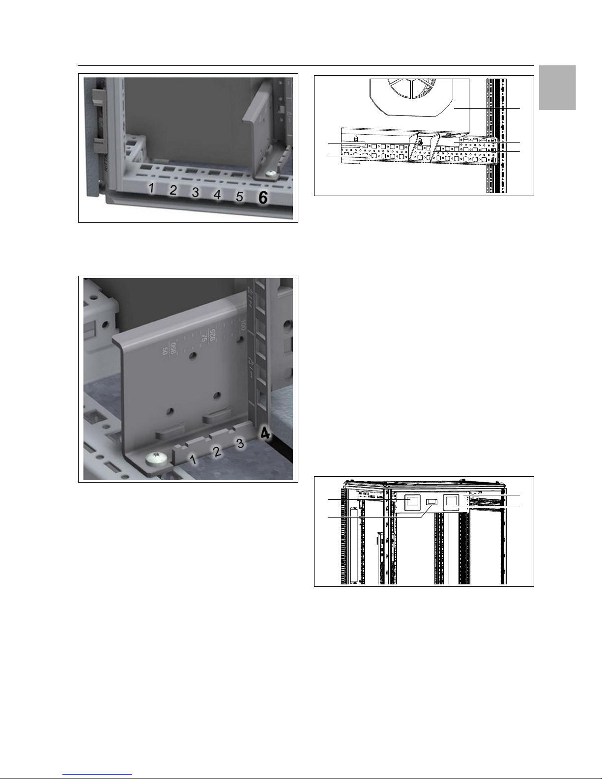
Fig. 7: Attachment points for external unit
Key
1 4 x M10 plugs per external unit
2Distance > 600mm
2
10
6
6
6
7
8
9
1
1
2
3
4
5
2
1 1
Page 15

Rittal LCU DX 15
5 Assembly and siting
EN
Fig. 8: Top view of attachment points
Key
1 For 3 kW unit: 550 mm
For 6.5 kW unit: 560 mm
2 Distance 1000 mm
3 For 3 kW unit: 325 mm
For 6.5 kW unit: 335 mm
4 12 x 20 mm elliptical drilled holes
1 12
3
4
Page 16

6 Installation
EN
16 Rittal LCU DX
6 Installation
6.1 General information
The internal unit and the external unit must be connected with suitable copper pipework. With the TS IT server
enclosure, this pipework can either be inserted into the
enclosure from above or from below.
When using in a Micro Data Center, a cable duct is provided and this must be used for inserting the pipework
into the safe.
In its delivered state, the internal unit is filled with 1.5 bar
nitrogen. It is therefore crucial that the following steps
are carried out in the order shown.
6.2 Notes on pipework
The following basic rules should be observed when connecting the internal unit and external unit.
General information
1. The pipes may only be made from special copper
piping that has been cleaned on the inside and
sealed at both ends. The material of the copper
pipework must comply with the specifications outlined in EN 12735-1 / EN 12735-2 and DIN 8964-3.
2. The external diameters of the copper pipes for the
intake gas line from the internal unit to the external
unit, as well as the liquid line from the external unit to
the internal unit, must comply with the values given
in section 11 "Technical specifications".
In order to ensure the correct spatial arrangement of the
pipework, particular consideration should be given to
the position of the individual pipes, the flow conditions
(two-phase flow, oil transportation in part-load operation), condensation processes, thermal expansion, vibration, and good accessibility.
As a general rule, pipelines should be laid in such a way
as to prevent damage associated with routine activities.
For safety reasons, and in order to protect the environment, the following aspects should be taken into account when laying pipework:
1. There must not be any threat to human safety, i.e.
escape and emergency vehicle routes must not be
obstructed or restricted in any way. No detachable
connections or fittings must be positioned in publicly
accessible areas.
2. Pipework should be protected from the thermal influence of hot lines and heat sources by means of
spatial separation.
3. Refrigerant lines must be protected or covered if
there is a risk of damage.
4. Flexible connecting parts such as connection lines
between indoor and outdoor devices that could become displaced during regular work operations
must be protected against mechanical damage.
5. The maximum distance between the supports of the
copper pipes is 1 m for pipelines with 1/4" to 3/8",
1.25 m for pipelines with 1/2" to 5/8" and 2 m for
pipelines with 3/4" to 7/8".
Laying the pipework
1. The equivalent length of the overall line between the
internal unit and the external unit must not exceed
the maximum length as set out in section 11 "Technical specifications". To calculate the equivalent
length, in addition to the actual length of the pipeline,
you should also make allowance for the equivalent
length of curves and valves.
2. The number of curves should be kept to a bare minimum so as to avoid pressure losses. Where curves
are unavoidable, the radius chosen should be as
large as possible.
3. Generally speaking, the lines between the internal
unit and external unit should take the shortest possible route. Exceptions are only admissible to avoid
unnecessary bends or circumvent extreme heat
sources.
4. Where possible, refrigerant lines should not be routed through rooms where people spend a lot of time,
such as offices or meeting rooms.
5. The intake gas line must be laid with an incline of 1%
in the direction of flow of the refrigerant.
6. When laying refrigerant lines, please ensure that
there is no overarching of liquid lines and no dipping
of gas lines (intake gas line). Oil could collect here, or
in the case of the liquid line, gas bubbles could form.
Caution! Risk of malfunction or damage!
Installation work, particularly the laying
of the refrigerant pipework between the
internal and external unit of the LCU DX,
must only be carried out by trained,
qualified and accredited cooling system
specialists.
Note:
Installation of the pipework, creation of a vacuum and filling with refrigerant must only be
carried out by qualified, accredited specialists in accordance with the valid technical
regulations.
Furthermore, when carrying out the installation, it is important to observe all the pipework instructions in section 6.2.
Note:
Routing and support of the pipework has a
significant influence on a cooling system's
operational reliability and service-friendliness.
Page 17

Rittal LCU DX 17
6 Installation
EN
7. For intake gas lines laid vertically with the direction of
flow pointing upwards (external unit is above the internal unit), an oil elevation arc should be provided at
least every 3 m of line length. The pre-insulated pairs
of lines may be laid with no distance between them.
Protecting the pipework
1. Suitable precautions should be taken to prevent excessive vibrations or pulsations. In particular, care
should be taken to prevent the direct transmission of
noise or vibrations onto or through the supporting
structure and the connected devices.
2. Safety devices, pipework and fittings should be protected from unfavourable environmental influences
as far as possible. Due consideration should be given to unfavourable environmental influences, such
as the risk of water collecting, relief lines freezing, or
dirt and waste accumulating.
3. With long pipelines, adequate precautions should be
taken with regard to expansion and contraction.
4. The pipelines of cooling systems should be designed and laid in such a way that the system cannot
be damaged by liquid slugging (hydraulic shock).
5. Pipelines with detachable connections must not be
positioned in public thoroughfares, vestibules, stairwells, steps, entrances, exits or in ducts or shafts
with unsecured openings to such areas, unless protected against disconnection.
6. Pipelines without detachable connections, valves,
control and regulatory devices that are protected
against accidental damage may be positioned in
public thoroughfares, stairwells or vestibules, provided they are situated at least 2.2 m above the
ground.
Pipe supports
1. Both horizontal and vertical lines must be laid with vibration-damping elements (such as rubber seals).
These must be used at a spacing of at least 2 m.
2. Take care to ensure that the first pipe support behind the internal unit and in front of the external unit
does not exert any mechanical pressure (via the
pipe) on the component. Pipe supports must not be
located too close to bends, to give the lines space
to expand.
Create the pipework system
1. To create the refrigerant pipework system, open the
ends of the lines on the internal unit. Upon opening,
gas should flow out audibly (from the nitrogen filling
provided in the factory) as an indication that there
are no leaks in the cooling circuit.
2. Only cut pipes to length using a pipe cutter.
3. Never saw pipes, as this could create swarf.
4. Only solder pipes under nitrogen or helium! To this
end, allow dry inert gas to flow into the pipe at one
end of the pipeline which has already been created.
Before starting, introduce a powerful current, reduce
this to a minimum when you start soldering, and
maintain this weak flow of protective gas throughout
the entire soldering process.
5. Before soldering the final connection, loosen the
screw connection on the external unit, or leave it untightened throughout, so that overpressure cannot
build up in the pipeline system. Immediately after
soldering, tighten the screw connection.
6. The pipelines may only be connected to the external
unit with flares. However, flare connections should
be restricted to soft pipes! After cutting the pipes to
length, adjust to the correct internal diameter with
light flaring. The flares must be tightened with the
prescribed torque using a torque wrench.
Low-temperature insulation of the liquid line and
intake gas line
1. Both lines outside and inside the building should be
equipped with low-temperature insulation to DIN
4140 made from UV-resistant HT/Armaflex or an
equivalent material.
2. We recommend a wall thickness of 9 mm
Leak test / conducting the leak test
The system must undergo leak testing as a complete
system. A test should also be carried out on site once
the installation is complete.
Multiple techniques may be used to test for leaks, depending on the manufacturing conditions, such as pressurisation with inert gas, or leak detection using radioactive gas. In order to avoid emissions of hazardous substances, the pressure test may be carried out with inert
gas such as nitrogen, helium or carbon dioxide. Oxyacetylene and hydrocarbons must not be used for safety
reasons. Air and gas mixtures are to be avoided, since
certain mixtures may be hazardous.
The manufacturer must select a test method which allows suitable results to be achieved in accordance with
the requirements outlined below.
Note:
Vibrations and pulsations should be assessed with the system operational at maximum condensation temperature and when
switching the system on and off, which has
unfavourable impacts on the pipework.
Note:
The internal unit is pressurised (filled with protective gas)!
Page 18

6 Installation
EN
18 Rittal LCU DX
Connections must be checked with a detector or using
a technique with a detection sensitivity as described in
EN 1779 with a bubble test (application of liquid) if the
test pressure is 1 x PS.
The manufacturer must verify that the test method used
complies with the aforementioned requirements.
EN 1779:1999 may be used as a basis for this test.
The detector must be calibrated at regular intervals as
per the manufacturer's instructions.
Any leak detected must be repaired and subjected to a
further leak test.
1. Systems with dry nitrogen should be tested at a
maximum overpressure of 28 bar. When doing so,
the shut-off valves on the external unit should remain
closed. The external unit is pre-filled with refrigerant
and this must not be allowed to escape.
2. Check the complete pipe network and the system
parts for leaks. We recommend using Nekal spray to
check every connection, including screw connections, for leak-proofness.
Evacuating
1. After checking for leaks, remove the air from the system. To do so, connect a vacuum pump and evacuate to a pressure of < 0.3 mbar (absolute pressure).
2. Break the vacuum at least twice, refill the system
with nitrogen, and evacuate again. Where possible,
implement double-sided evacuation of the suction
side and the pressure side of the compressor, to
which end a test/measurement connection must be
made in the liquid line.
Filling with refrigerant
1. The external unit is prefilled in the factory, the fill volume is adequate for a 5 m line pair. For longer pipe
lengths, additional refrigerant should be added in
accordance with section 11 "Technical specifications".
2. The system must only be filled gravimetrically (i.e. by
weight) using refrigerant as the liquid in the liquid
line. Only liquid R410A should be added. Afterwards, switch on the device and whilst it is running,
continue carefully restricted filling via the intake side
of the external unit until the required fill volume has
been added.
3. The set volume of refrigerant is determined by
weighing the refrigerant bottle during the filling process.
4. The additional fill volume or the new total fill volume
should be noted on the rating plate and operating
manual.
6.3 Connecting the condensate discharge
Any condensate which may develop is collected in the
condensate collecting tray of the internal unit. For universal use, the internal unit has two condensate collecting
trays which may be fitted on the left or right of the enclosure, depending on the installation position.
Connect the discharge hose supplied loose (internal
diameter 12 mm) at the bottom connection (external
diameter 12 mm).
The tray at the top is not used.
Route the discharge hose to a drain with odour seal
provided by the customer, so that any condensate
can be discharged from the device.
6.4 Electrical connection
6.4.1 General
The electrical connection can only be made on the external unit. The internal unit is supplied with power via
the external unit. A 3-wire power cable should be used
for this purpose. The corresponding pilot wires from the
internal unit to the external unit should be laid with the refrigerant lines in accordance with section 11.7 "Circuit
diagram".
Note:
Lower test pressures are admissible, provided there is an equivalent detection sensitivity.
Note:
In order to ensure safe condensate discharge, the following points should be observed:
– Lay the discharge hose so that it always
runs downhill and without any kinks.
– Do not constrict the hose cross-section.
Note:
Please keep the wiring plan readily available
so that it is always on hand when needed.
This is the only authoritative documentation
for this unit.
Caution!
Work on electrical systems or equipment may only be carried out by an electrician or by trained personnel under the
guidance and supervision of an electrician. All work must be carried out in accordance with electrical engineering
regulations.
Contact with live electrical parts may result in fatal injury.
The unit may only be connected after the
aforementioned personnel have read
this information!
Use only insulated tools.
Page 19

Rittal LCU DX 19
6 Installation
EN
6.4.2 Connecting the external unit
Power is supplied to the external unit via a 3-wire connection cable (230–240 V, 1~, N, PE). As external units
are generally sited outdoors, a UV-resistant cable should
be used.
Strip approximately 45 mm from the rubber sheathing
of the connection cable.
Trim the neutral conductor (N) and the phase conductor (L) to a length of approximately 35 mm. Leave the
length of the PE conductor at approximately 45 mm.
Remove approximately 9 mm from the insulation of all
conductors with a suitable tool.
Fig. 9: Dimensions for removing the rubber sheathing and in-
sulation
Attach wire end ferrules without insulating collar to the
ends of the cables, using a four-jaw pressing tool.
Insert the cable into the connection box in the device
from below.
Attach the cooling unit to the strain relief provided.
Connect the cable in the connection box as shown in
the circuit diagram in section 11.7 "Circuit diagram" to
the correspondingly labelled terminals (PE, L1, N).
Connect the external units using an all-pole isolating
device as described in DIN EN 60335-2-40. This disconnector device must ensure at least 3 mm contact
opening when switched off.
The customer should provide a pre-fuse in the supply
line to the external unit, as specified on the rating plate
of the device.
6.4.3 Connecting the internal unit
Connecting the internal unit simply entails connecting
the cables routed from the external unit, which comprise
a data line and a 230 V pilot wire as described in
section 11.7 "Circuit diagram".
The fault signals may be picked off at the internal unit
(floating contacts).
Should you wish to switch the internal unit on and off
via a remote switch (e.g. for an external fire shutoff),
connect a remote contact (normally open contact) in
the electronic box to terminals L1 and 11 for the "single" version and terminals L1 and 11 as well as L2 and
23 ("remote" or "ON/OFF") for the "redundant" version
(see section 11.7.3 "Circuit diagram, external unit"). In
the closed state, the system is then deactivated.
If both terminals are jumpered, the status message
"– –" will appear in the display.
6.5 Checking the entire system prior to
commissioning
Before operating the cooling system, the entire system,
including the complete cooling system, must be
checked for conformity with the relevant diagrams, system flow charts and piping and instrumentation diagrams, and wiring plans.
Cooling systems must be checked by a trained plant inspector (as defined in EN 13313) and should include a
review of the following points:
1. Inspect the documents.
2. Check the safety switchgear for pressure limiting to
ensure that the safety switchgear for pressure limiting is operational and correctly installed.
3. Check selected hard solder connections on pipe-
work for compliance with EN 14276-2.
Caution!
Follow the connection regulations of the
appropriate electrical power company.
The voltage specified in the wiring plan
or on the rating plate must match the
mains voltage.
The unit has a high discharge current.
Before connecting to the supply circuit,
therefore, it is essential to make a 6 mm²
earth connection (see section 11.7 "Circuit diagram").
The pre-fuse specified in the wiring
plan / rating plate should be provided to
protect the cable and equipment from
short-circuits. The unit must be individually fused.
The unit must be connected to the mains
using an all-pole red/yellow isolating device as described in DIN EN 60335-2-40,
which ensures at least 3 mm contact
opening when switched off.
No additional control equipment may be
connected upstream of the device at the
supply end.
45
99
Danger!
Take utmost care not to short-circuit the
phase conductor with the zero conductor or the earth conductor. Otherwise,
there is a risk of damage or injury.
Page 20

6 Installation
EN
20 Rittal LCU DX
4. Check the refrigerant pipelines.
5. Inspect the report on the cooling system leak test.
6. Visually inspect the cooling system.
7. Check the labels.
This inspection must be documented; see EN 378-2,
section 6.4.3. No cooling system may be operated without the correct documentation.
The installer must document the fact that the system
was installed in accordance with the construction requirements and state the safety and control device settings, if adjustable, following commissioning. This documentation must be kept by the installer and presented
upon request.
6.6 Installing the server
As a general rule, the cooling system is designed for
"front to back" cooling – in other words, the devices installed in the enclosure must likewise follow this air routing. To this end, the area in front of the 482.6 mm (19")
level is supplied completely with cold air. The servers
draw the cooling air they require from this area, and expel the warm air downwards or sideways. The area at
the rear may reach a high temperature. This is intentional, since it increases the transmission performance of
the heat exchanger in the internal unit.
Distribute the equipment you wish to install evenly
across the 482.6 mm (19") level.
Close any areas you do not require with 482.6 mm
(19") blanking plates.
Cover the side opposite the internal unit in the enclosure with an air baffle plate (see section 13 "Accessories").
Fig. 10: Air baffle plate on the side opposite the LCU internal
unit
Key
1 Air baffle plate
Exchange the brush strip of the standard air baffle
plate in the TS IT server enclosure for the brush strip
with shorter brushes included with the supply of the
LCU DX.
The brush strip is included with the supply in two
parts.
Remove the top corner of the air baffle plate near the
TS frame using an angle grinder or other suitable tool.
Fig. 11: Cut-out in the air baffle plate
Key
1TS frame
2 Cut-out for TS frame
3 Air baffle plate
Fig. 12: Dimensions of the cut-out
Partition the remaining gap between the 482.6 mm
(19") level and the internal unit, as well as above and
below the internal unit, using the foamed plastic supplied loose with the LCU DX.
Cut the foamed plastic to the required size.
1
2
3
1
45
Page 21

Rittal LCU DX 21
6 Installation
EN
Fig. 13: Partitioning with foamed plastic pieces on the side of
the LCU internal unit
Key
1 Partitioning above
2 Partitioning inside
3 Partitioning below
3
1
2
Page 22

7 Operation
EN
22 Rittal LCU DX
7Operation
This section describes operation of the LCU DX using
the control and display devices.
7.1 Control and display devices
Control and display device 1 is located in the 3U trim
panel on the maintenance side of the rack. In the "single"
version, there is one such display device installed, and in
the "redundant" version there are two.
Fig. 14: Control and display device 1
Key
1ON/OFF button
2 "Up" button (temperature)
3 "Down" button (temperature)
Control and display device 2 is likewise located in the
3U trim panel on the maintenance side of the rack. In
both the "single" version and in the "redundant" version,
there is only one control device of this type installed.
In addition to control and display device 1, control and
display device 2 regulates the start-up response following a power failure or if the minimum cooling load is undercut.
Fig. 15: Control and display device 2
Key
1 "Up" button (temperature)
2 "Down" button (temperature)
3ON/OFF button
4Set button
5 Defrost switch (deactivated)
6Light
Control and display device 3 is located on the end face
of the internal unit. In the "single" version, there is one
such control and display device installed, and in the "redundant" version there are two.
The operating status can be read from control and display device 3 on the internal unit. In addition to the con-
trol lights for operation, malfunction and defrost, the set
temperature or a fault code can be read from the twodigit LCD display.
Fig. 16: Control and display device 3
Key
1 Manual (to request operating statuses)
2 Operation (permanently illuminated during operation,
flashes when the system is being booted up)
3 Timer (no function)
4DEF/FAN (no function)
5 Alarm (flashes red in case of malfunction)
6 LCD display 1 and 2 (displays a fault code in case of an
alarm)
7.2 Switching the LCU DX on and off
7.2.1 Switching on the internal and external units
Once both the internal unit and the external unit are electrically connected, carry out the following two steps:
Switch on the on-site power supply to the external
unit.
The internal unit is supplied with power via the external
unit.
Switch on the LCU DX on control and display device 1
using the "ON/OFF button".
7.2.2 Switching off the internal and external units
To switch off the LCU DX and the condenser, proceed
as follows:
Switch off the LCU DX on control and display device 1
using the "ON/OFF button".
Switch off the on-site power supply to the external
unit.
7.2.3 Switching off in an emergency
To switch off the LCU DX in an emergency, proceed as
follows:
Switch off the on-site power supply to the external
unit.
7.3 Setting the setpoint temperature
The setpoint temperature (outlet temperature of the internal unit or server air intake temperature) is set on control and display devices 1 and 2 using the arrow keys. It
is essential that both values are set identically.
Observe the manufacturer's information on temperature
settings for the components built into the server enclosure. We recommend a setting within the range 22°C–
25°C. Because the LCU DX cannot actively regulate humidity, where necessary the set temperature should be
adjusted in line with the ambient conditions.
2
1
3
2
1
3
5
6
4
1 2345 6 7
Page 23

Rittal LCU DX 23
7 Operation
EN
First set the required setpoint temperature on control
and display device 1.
For the "redundant" version, also set the same setpoint temperature on control and display device 2.
On control and display device 2, keep the Set button
held down for 3 seconds.
Your setting is displayed.
Using the arrow keys, set the same setting as previously set on control and display device 1.
Confirm this value by pressing the Set button again.
The setpoint is displayed on control and display unit 2.
As a general rule, the setpoints on all control components should be set to the same value.
Page 24

8 Troubleshooting
EN
24 Rittal LCU DX
8 Troubleshooting
8.1 General
If there is a malfunction or alarm on the device, a corresponding error message will be displayed on control and
display device 3. In the event of a serious malfunction,
the red LED will be illuminated and the alarm relay will
switch (collective fault signal). The corresponding fault
code may be read from the 2-digit LCD display.
8.2 List of error messages
Note:
For technical queries, or if servicing is required, please contact Rittal using the addresses shown in section 15 "Customer
service addresses".
No. Description of malfunction LED 1
Operation
LED 2
Timer
LED 3
DEF. FAN
LED 4
Alarm
Malfunction
code in
display
1 Clash between operating modes 5 Hz E0
2
Communication malfunction between internal and external unit
5Hz E1
3
Temperature sensor for server air intake
defective or missing
5Hz E2
4
Pipe temperature sensor T2 defective or
missing
5Hz E3
5
Register temperature sensor T2B defective or missing
5Hz E4
6 EEPROM defective 1 Hz E7
7 Error in external unit 1 Hz Ed
8
KJR 10 B blocked by operation with remote ON/OFF contacts on the clamping
strip
1Hz CP
9
Display cold air or defrosting Continu-
ous light
Continuous light
Page 25

Rittal LCU DX 25
9 Inspection and maintenance
EN
9 Inspection and maintenance
The following maintenance work should be carried out
on the LCU DX:
– The condensate discharge device should be checked
regularly for correct functioning.
– Regularly check the refrigerant circuit and all main
components for correct functioning (at least once a
year according to DIN EN 378).
– Regularly check for leaks using a suitable device (an-
nually) as required by the F-gas regulation (see
section 2.3.3 "F-gas regulation" and section 2.3.4
"Chemicals – Climate Protection Ordinance").
Note:
At an ambient temperature of 40°C, the nominal service life of the built-in fan is 40,000 operating hours.
Page 26

10 Storage and disposal
EN
26 Rittal LCU DX
10 Storage and disposal
During storage, both the internal as well as the external
unit must stand upright.
Disposal can be performed at the Rittal plant.
Please contact us for advice.
Caution! Risk of damage!
The LCU DX must not be subjected to
temperatures above +50°C during storage.
Caution! Risk of environmental contamination!
Never allow refrigerant from the cooling
circuit or oil from the compressor to escape into the environment.
Refrigerant and oil must be properly disposed of in accordance with the valid
national legislation and regulations.
Page 27

Rittal LCU DX 27
11 Technical specifications
EN
11 Technical specifications
11.1 LCU DX 3 kW
Technical specifications Internal unit
External unit
Description/Model No. 3311490: LCU DX 3 kW "single" version
Description/Model No. 3311491: LCU DX 3 kW "redundant" version
Dimensions and weight
Dimensions (width x height x depth) [mm] 105 x 1550 x 820 810 x 558 x 310
Weight, max. [kg] 48 38
Electrical connection
Type of electrical connection Connection clamp
Rated voltage [V, Hz] 1~/N/PE 230, 50
Rated current [A] 7
Start-up current [A] 4.9
Pre-fuse T [A] – 16
Max. power consumption [kW] 1.6
Duty cycle [%] 100 100
Cooling output
Nominal cooling output [kW] L22* L35 3.5 (* server inlet air temperature)
Power consumption at nominal cooling output [kW] L22* L35 1.35 (* server inlet air temperature)
Energy Efficiency Ratio (EER) L22 L35 2.6
Air throughput, max. [m
3
/h] 2,500
Cooling circuit
Refrigerant / filled weight [kg] R410A/1.8 (Fluid Group 2)
Additional refrigerant from the 5th metre [g/m] 30
Max. permissible pressure [bar] PS HP: 42
PS LP: 28
Pipe cross-section, intake gas line 1/2"
Pipe cross-section, liquid line 1/4"
Other information
Storage temperatures [°C] -20…+50
Temperature range [°C] +15…+35 -20…+45
IP protection category IEC 60529 IP 20 IP X4
Noise level [dB (A)] 65 (distance 1 m) 40 (Open air above reflective
flooring, distance 10 m)
Colour RAL 7035 White
Tab. 6: Technical specifications for the LCU DX 3 kW
Page 28

11 Technical specifications
EN
28 Rittal LCU DX
11.2 LCU DX 6.5kW
Technical specifications Internal unit
External unit
Description/Model No. 3311492: LCU DX 6.5 kW "single" version
Description/Model No. 3311493: LCU DX 6.5 kW "redundant" version
Dimensions and weight
Dimensions (width x height x depth) [mm] 105 x 1550 x 820 845 x 700 x 320
Weight, max. [kg] 48 48
Electrical connection
Type of electrical connection Connection clamp
Rated voltage [V, Hz] 1~/N/PE 230, 50
Rated current [A] 15.9
Start-up current [A] 5.4
Pre-fuse T [A] – 20
Max. power consumption [kW] 3.6
Duty cycle [%] 100 100
Cooling output
Nominal cooling output [kW] L22* L35 6.2 kW (* server inlet air temperature)
Power consumption at nominal cooling output [kW] L22* L35 3.14 kW (* server inlet air temperature)
Energy Efficiency Ratio (EER) L22 L35 1.97
Air throughput, max. [m
3
/h] 4,800
Cooling circuit
Refrigerant / filled weight [kg] R410A/1.8 (Fluid Group 2)
Additional refrigerant from the 5th metre [g/m] 30
Max. permissible pressure [bar] PS HP: 42
PS LP: 28
Pipe cross-section, intake gas line 5/8"
Pipe cross-section, liquid line 3/8"
Other information
Storage temperatures [°C] -20…+50
Temperature range [°C] +15…+35 -20…+45
IP protection category IEC 60529 IP 20 IP X4
Noise level [dB (A)] 66 (distance 1 m) 40 (Open air above reflective
flooring, distance 10 m)
Colour RAL 7035 White
Tab. 7: Technical specifications for the LCU DX 6.5 kW
Page 29

Rittal LCU DX 29
11 Technical specifications
EN
11.3 Information about the refrigerant
To avoid damage to the device, Rittal prescribes the use
of refrigerant R410A.
R410A is virtually azeotropic and is comprised of equal
parts of R32 and R125. The basic properties of R410A
are:
– No ozone depletion potential
–Clear
– Liquefied gas smelling of ether
– Non-combustible
– Low toxicity
11.4 Cooling output
Due to the device configuration comprising two subunits, and the partially linear operation of the components (fan, inverter-controlled cooling unit), the cooling
output of the device is dependent on various factors:
– External temperature at the installation site of the ex-
ternal unit
– Thermal output from the server enclosure
– Inlet temperature of hot air into the internal unit
– Settings
– Position of the sensor on the front of the server
Due to the control response, the temperature directly at
the air outlet of the internal unit may fluctuate between
-3 K and +4 K. A fluctuation period lasts one to two minutes. On average, the temperatures at the air outlet of
the internal unit are within the tolerance of ±2 K.
Caution!
The LCU DX may only be operated with
refrigerant R410A. Use of any other refrigerant will invalidate the guarantee.
Caution! Risk of malfunction or damage!
Installation, and in particular laying of
the refrigerant pipework between the internal and external unit of the LCU DX,
must only be carried out by trained,
qualified and accredited cooling system
specialists.
Property Value
Composition 50%: R32 (CH
2F2
)
50%: R125 (C2HF5)
Molar mass [g/mol] 72.585
Boiling point [°C] -52.7
Vapour pressure [bar] 12.46 at 15°C
Relative density 1.11 at 15°C
Tab. 8: Material data for R410A
Note:
Safety data sheets are available for downloading at www.rittal.com.
Page 30

11 Technical specifications
EN
30 Rittal LCU DX
11.4.1 LCU DX 3 kW
Exterior temperature [°C] -18
Setpoint [°C] ± 2 K 222528
Cooling output [kW] min./max. 1.00 3.00 1.00 3.00 1.00 3.00
Power consumption [kW] 0.41 0.64 0.46 0.65 0.45 0.68
Tab. 9: Exterior temperature -18°C
Exterior temperature [°C] -5
Setpoint [°C] ± 2 K 222528
Cooling output [kW] min./max. 1.00 3.00 1.00 3.20 1.00 3.50
Power consumption [kW] 0.46 0.57 0.46 0.66 0.46 0.68
Tab. 10: Exterior temperature -5°C
Exterior temperature [°C] 10
Setpoint [°C] ± 2 K 222528
Cooling output [kW] min./max. 1.00 3.50 1.00 3.50 1.00 3.50
Power consumption [kW] 0.43 0.62 0.45 0.69 0.48 0.68
Tab. 11: Exterior temperature 10°C
Exterior temperature [°C] 20
Setpoint [°C] ± 2 K 222528
Cooling output [kW] min./max. 1.00 3.50 1.00 3.50 1.00 3.50
Power consumption [kW] 0.49 0.99 0.46 1.05 0.49 0.68
Tab. 12: Exterior temperature 20°C
Exterior temperature [°C] 35
Setpoint [°C] ± 2 K 222528
Cooling output [kW] min./max. 1.00 3.50 1.00 3.50 1.00 3.50
Power consumption [kW] 1.00 1.35 0.62 1.43 0.62 0.68
Tab. 13: Exterior temperature 35°C
Exterior temperature [°C] 44
Setpoint [°C] ± 2 K 222528
Cooling output [kW] min./max. 1.00 3.50 1.00 3.50 1.00 3.50
Power consumption [kW] 1.02 1.45 0.97 1.52 0.97 0.68
Tab. 14: Exterior temperature 44°C
Page 31

Rittal LCU DX 31
11 Technical specifications
EN
11.4.2 LCU DX 6.5 kW
Exterior temperature [°C] -18
Setpoint [°C] ± 2 K 22 25 28
Cooling output [kW] min./max. 3.006.503.006.503.006.50
Power consumption [kW] 1.45 2.03 1.66 2.10 1.52 2.10
Tab. 15: Exterior temperature -18°C
Exterior temperature [°C] -5
Setpoint [°C] ± 2 K 22 25 28
Cooling output [kW] min./max. 3.006.503.006.503.006.50
Power consumption [kW] 1.65 2.10 1.48 2.10 1.60 2.10
Tab. 16: Exterior temperature -5°C
Exterior temperature [°C] 10
Setpoint [°C] ± 2 K 22 25 28
Cooling output [kW] min./max. 3.006.503.006.503.006.50
Power consumption [kW] 1.57 2.06 1.53 2.18 1.66 2.18
Tab. 17: Exterior temperature 10°C
Exterior temperature [°C] 20
Setpoint [°C] ± 2 K 22 25 28
Cooling output [kW] min./max. 3.006.503.006.503.006.50
Power consumption [kW] 1.80 2.63 1.86 2.67 1.89 2.67
Tab. 18: Exterior temperature 20°C
Exterior temperature [°C] 35
Setpoint [°C] ± 2 K 22 25 28
Cooling output [kW] min./max. 3.006.203.006.503.006.50
Power consumption [kW] 2.18 3.14 2.27 3.20 2.27 3.12
Tab. 19: Exterior temperature 35°C
Exterior temperature [°C] 44
Setpoint [°C] ± 2 K 22 25 28
Cooling output [kW] min./max. 3.004.003.004.003.005.00
Power consumption [kW] 1.66 1.80 1.72 1.96 1.80 2.25
Tab. 20: Exterior temperature 44°C
Page 32

11 Technical specifications
EN
32 Rittal LCU DX
11.5 Overview drawings
11.5.1 Internal unit LCU DX 3 kW and 6.5 kW
Fig. 17: Overview drawing of internal unit LCU DX 3 kW and 6.5 kW ("redundant" version)
Key
1 Insert for data and supply cables
2 Refrigerant line for "single" version (1 pair)
3 Refrigerant line for "redundant" version (2 pairs)
4 Condensate discharge
2/3
2/3
1
3
3
4
1
Page 33

Rittal LCU DX 33
11 Technical specifications
EN
11.5.2 Dimensions of internal unit LCU DX 3 kW and 6.5 kW
Fig. 18: Dimensions of internal unit LCU DX 3 kW and 6.5 kW
Outlet zone for cold air
Condensate runoff for left-side installation
Refrigerant connections
Inspection opening for electronics
Condensate runoff for right-side installation
Intake zone for hot air
Mounting holes
Page 34

11 Technical specifications
EN
34 Rittal LCU DX
11.6 RI flow chart LCU DX
Fig. 19: RI flow chart
Shut-off valve
Internal part External part
Electronic
expansion valve
Capillaries Capillaries
Condenser
Evaporator
coil
4-way valve
Compressor
Cooling
Heating
Accumulator
Refrigerant,
gas
Refrigerant,
liquid
Page 35

Rittal LCU DX 35
11 Technical specifications
EN
11.7 Circuit diagram
11.7.1 Functional diagram, internal unit
Fig. 20: Functional diagram, internal unit
Redundancy changeover
Remote control (3 U)
Control and display
device 1
Control and display
device 1
"redundant"
Control and display
device 2
DIXELL
Control and display device 3
Control and display device 3
WAGO
connector
X3
Sensor A
Optional
Fans 1 and 2 Fans 1-4
Midea
Motherboard, internal unit
WAGO connector, internal unit A
Electrical connection diagram
Midea
Motherboard, internal unit
"Redundant" version only
WAGO connector, internal unit B
Page 36

11 Technical specifications
EN
36 Rittal LCU DX
11.7.2 Connection internal unit – external unit, external interfaces
Fig. 21: Connection internal unit – external unit, external interfaces
COM-NO
Connector, internal unit A
SK 3311.490 to SK 3311.493
Connector, internal unit B
SK 3311.491 and SK 3311.493
Caution: 230 V~
Remote switching on/off
Shielded cable
Shielded cable
Collective fault signal
Operation
Connection by the customer
Open = On
COM-NC
COM-NO
Caution: 230 V~
Remote switching on/off
Collective fault signal
Operation
Open = On
COM-NC
Connection by the customer
Connection by the customer
SK 3311.490, …491, …492 and …493
Voltage 230 V~/1/N/PE, 50 Hz
External unit A
Supply lead
Connection by the customer
SK 3311.491 and …493
Voltage 230 V~/1/N/PE, 50 Hz
External unit B
Supply lead
Electrical connection diagram,
internal unit – external unit
Page 37

Rittal LCU DX 37
11 Technical specifications
EN
11.7.3 Circuit diagram, external unit
Fig. 22: Circuit diagram, external unit
IPM board
Inverter board
Motherboard
External temperature
sensor
Register sensor
Hot gas sensor
Electronic
expansion
valve
4-way valve
Compressor heater
Floor heating
DC
fan
motor
Compressor
Main supply lead
3 x 2.5 mm²
Fuse as per table
Connection cable
to internal unit
3 x 2.5 mm²
Pilot wire
3 x 0.75 mm²
Only shielded cable should
be used as the pilot wire
Inductor coil
Page 38

12 Spare parts
EN
38 Rittal LCU DX
12 Spare parts
Item Qty. / Packs of
Evaporator coil control board 1
Display 1
Compressor 1
Inverter motherboard 1
Electronic expansion valve 1
Evaporator coil fan 1
Dixell (evaporator coil) 1
Temperature sensor hot/cold air 1
Refrigerant filter 2
Tab. 21: List of spare parts – LCU DX
Page 39

Rittal LCU DX 39
13 Accessories
EN
13 Accessories
Item Model No. Qty. / Packs of Remarks
Refrigerant pipe kit 1
Refrigerant pipe kit 20 m, insulated, for LCU DX 3 kW 3311.495 1
Refrigerant pipe kit 20 m, insulated, for LCU DX
6.5 kW
3311.496 1
Tab. 22: List of accessories – LCU DX
Page 40

14 Glossary
EN
40 Rittal LCU DX
14 Glossary
1U server:
1 U servers are very flat and deep, modern high performance servers, whose height corresponds to one
height unit (1 U = 44.54 mm, the smallest standard
height division). Typical dimensions are (W x D x H)
482.6 mm (19") x 800 mm x 1 U.
These systems normally include 2 CPUs, many GB
RAM and hard drives, so that they require up to
100 m
3
/h cooling air at a maximum of 32°C.
482.6 mm (19") level:
The front sides of the devices built into the server enclosure form the 482.6 mm (19") level.
Blade server:
By orienting dual CPU systems vertically and placing
up to 14 units on a common backplane to provide for
signal routing and power supply, a blade server is created.
Blade servers can "generate" up to 4.5 kW heat loss
per 7 U and 700 mm depth.
"Front to back" cooling principle:
The devices built into the server enclosure are normally
cooled according to the "front to back" cooling principle.
Under this cooling principle, cold air supplied by external air conditioning is blown to the front of the server
enclosure. The fans in the devices built into the server
enclosure direct this air horizontally through the server
enclosure. The air is warmed through this process and
is exhausted out of the rear of the enclosure.
Hot spot:
A hot spot is the concentration of thermal energy in a
small area.
Hot spots normally lead to local overheating and can
cause system malfunctions.
Switch:
Multiple servers normally communicate with one another and in the network using switches.
Because as many inputs as possible are located on
the front side of switches, they frequently have an airflow from the side, not "front to back" cooling.
Page 41

Rittal LCU DX 41
15 Customer service addresses
EN
15 Customer service addresses
For technical queries, please contact:
Tel.: +49(0)2772 505-9052
E-mail: info@rittal.de
Homepage: www.rittal.com
For complaints or service requests, please contact:
Tel.: +49(0)2772 505-1855
E-mail: service@rittal.de
Rittal GmbH & Co. KG
Auf dem Stützelberg
35745 Herborn
Germany
Page 42

◾Enclosures
◾ Power Distribution
◾Climate Control
◾ IT Infrastructure
◾ Software & Services
You can find the contact details of all
Rittal companies throughout the world here.
www.rittal.com/contact
02.2016
 Loading...