

Rittal 3105, 3105.330, 3105.310, 3105.320, 3105.350 Assembly And Operating Instructions Manual
...Page 1

SchaHtschraJGHeiVuJg
EJcHKsure heater
RËsistaJces chauffaJtes
SchaGeHGastverwarIiJgeJ
VÇrIeeHeIeJt f×r apparatsGÈp
RiscaHdatKre aJticKJdeJsa
ResisteJcia caHefactKra
エンクロージャー用ヒーター
3105XXX
*KJtage IJstaHHatiKJs uJd BedieJuJgsaJHeituJg
AsseIbHy aJd KperatiJg iJstructiKJs
*aJueH d’iJstaHHatiKJ et de IaiJteJaJce
*KJtage eJ bedieJiJgshaJdHeidiJg
*KJtage Kch haJteriJgsaJvisJiJg
IstruViKJi di IKJtaggiK e fuJViKJ
IJstrucciKJes de IKJtaFe
取扱説明書
aIeJtK
Page 2

ENEN
Contents
1 Notes on documentation. . . . . . . 3
1.1 Other applicable documents . . . 3
1.2 CE certification . . . . . . . . . . . . . . 3
1.3 Storing the documents . . . . . . . 3
1.4 Symbols used. . . . . . . . . . . . . . . 3
2 Safety notes . . . . . . . . . . . . . . . . . 3
3 Device description . . . . . . . . . . . . 4
3.1 Functional description. . . . . . . . 4
3.1.1 How it works. . . . . . . . . . . . . . . . . 4
3.1.2 Control . . . . . . . . . . . . . . . . . . . . . 4
3.2 Proper use . . . . . . . . . . . . . . . . . 4
3.3 Scope of supply . . . . . . . . . . . . . 4
4 Mounting . . . . . . . . . . . . . . . . . . . . 5
5 Electrical connection . . . . . . . . . . 5
6 Storage and disposal. . . . . . . . . . 6
7 Warranty . . . . . . . . . . . . . . . . . . . . 6
8 Technical specifications . . . . . . . 6
9 Dimensions. . . . . . . . . . . . . . . . . . 7
2 Rittal enclosure heater assembly instructions
Page 3
1 Notes on documentation
EN
䡲
1 Notes on documentation
These assembly instructions are aimed at
– tradespersons who are familiar with
assembly and installation of the heater
– trained specialists who are familiar with
operation of the heater
1.1 Other applicable documents
Assembly and operating instructions exist
as paper documents for the unit types
described here and are enclosed with the
equipment.
We cannot accept any liability for damage
associated with failure to observe these instructions. Where applicable, the instructions
for any accessories used also apply.
1.2 CE certification
The declaration of conformity is supplied with
the unit as a separate document.
1.3 Retention of documents
These instructions and all associated
documents constitute an integral part of the
product. They must be given to the plant
operator. The operator is responsible for
storage of the documents so they are readily
available when needed.
2 Safety notes
– When performing the electrical installation,
it is important to observe all valid national
and regional regulations as well as the
provisions of the responsible electrical
supply company.
– Electrical installation must only be carried
out by a qualified electrician who is
responsible for compliance with the
existing standards and regulations.
– Use only original spare parts!
– The heater must not be touched while
switched on. Risk of burns from hot
surfaces! The heater must be allowed to
cool for approx. 15 minutes after switching
off.
Caution!
Risk of burns from hot surfaces!
1.4 Symbols used
The bullet point indicates an
action to be performed.
Danger!
Immediate danger to life and
limb!
Caution!
Potential threat to the product
and its environment.
Note:
Useful information and special
features.
Rittal enclosure heater assembly instructions 3
Page 4
3 Device description
EN
Without fan
With fan
1 3
4
2
1 3
4
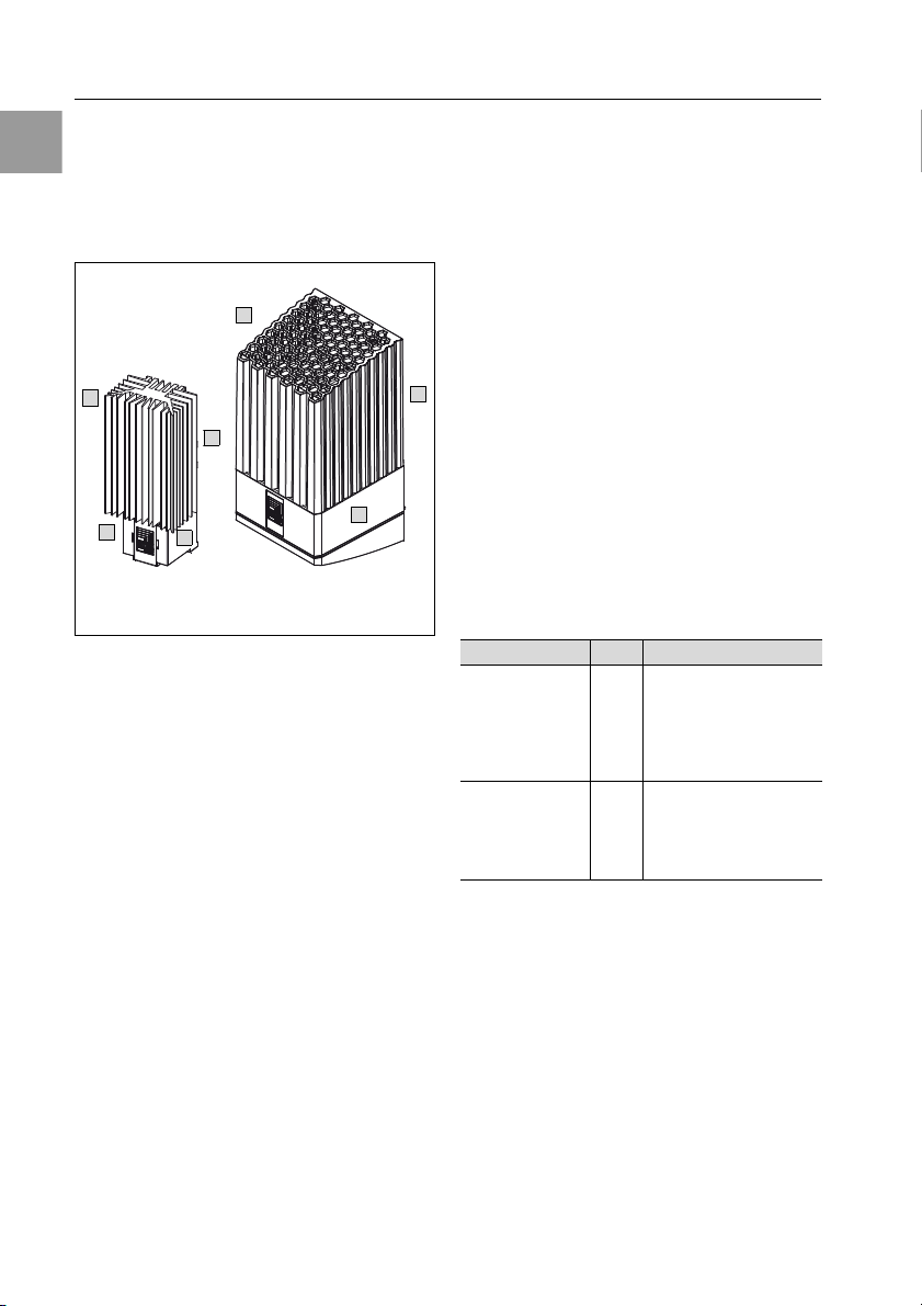
3 Device description
Depending on the model chosen, your heater
may vary in appearance from the illustrations
contained in these instructions.
However, the functions are identical in
principle.
Fig. 1: Device description
(ey
1 Aluminium section (without fan) or heater
housing (with fan)
2 Protective cover for electrical connection
3 Base plate
4 Fixing points
3.1 Functional description
Heaters are used to prevent the formation of
condensation inside the enclosure and
maintain a constant minimum operating
temperature (e.g. when the system is
switched off overnight).
Rittal heaters achieve thermal outputs of
8 to 870 watts.
3.1.1 How it works
The heaters are comprised of the following
main components:
Heaters without fan
– Aluminium section
– PTC heater element
Heaters with fan
– PTC heat register
–Fan
3.1.2 Control
A separate thermostat (3110.000) or a digital
thermostat (3114.200) must be used to control the enclosure temperature. The humidity
of the air in the enclosure can be controlled
by incorporating a hygrostat (3118.000).
3.2 Proper use
Rittal heaters were developed and designed
in accordance with the state of the art and the
recognised rules governing technical safety.
Nevertheless, if used improperly, they may
pose a threat to life and limb or cause damage to property. The heater is designed to
heat closed enclosures that are only accessible by trained specialists. The admissible
temperature range is -33°C to +65°C. The
manufacturer will not be liable for any damages caused as a result of improper use, or for
incorrect assembly, installation or use. All risk
is borne solely by the user.
3.3 Scope of supply
The heater is supplied in one packaging unit.
*KdeH +K Qty DesigJatiKJ
3105.310 – .370 1
3105.380 – .430 1 1 Heater
Tab. 1: Scope of supply
Base plate
1
Aluminium section
1
Cover cap
1
Assembly instructions
Assembly parts
(see fig. 2)
(pre-assembled)
Assembly instructions
Assembly parts
(see fig. 2)
4 Rittal enclosure heater assembly instructions
Page 5

5 Electrical connection
EN
4 Mounting
The heater is fitted vertically, i.e. with the connection terminal or fan facing downwards. To
permit the required convection, a minimum
clearance to the adjacent components must
be observed. A safety clearance of at least
300 mm must be left at the air outlet in the
case of heaters with fans, and 100 mm for
heaters without fans. (For both heaters a thermal safety clearance to the sides of 60 mm
and 100 mm at the bottom is required). If
these clearances are observed, the ambient
temperature at the air inlet does not rise
above 65°C.
There are two different methods of
assembling the heater:
1. Snap-type fastening onto a 35 mm support
rail DIN EN 50 022 (fig. 2).
2. Screw fastening onto the mounting plate
(fig. 3).
It should be ensured that the heater and
connection cables are mounted firmly and
securely.
Electric cables must not touch the body of
the heater fan and must not be routed directly
past the hot air outlet.
The heater must not be mounted in the
vicinity of flammable materials.
5 Electrical connection
The heater must be connected, via the quickconnect terminals, to a power supply of the
voltage stated on the rating plate.
The heater must be connected to the
mains via an all-pole isolating device in
accordance with the overvoltage category III
to EN 60 664-1. Only copper wires are to be
used for the electrical connection. Due to
the special characteristics of the PTC heater
element, a current of up to 4.4 A may be
reached for a short time when the heater is
switched on.
Slow-blowing fuse-links (gG) or circuitbreakers with a corresponding delayed-trip
characteristic can be used as pre-fuses. The
required pre-fuse rating is specified on the
rating pate. Overvoltage protection is to be
provided where pulse loads exceeding
1,000 V are possible. The double connection
terminal permits the cascading of several
heaters and thus simplifies wiring. In such
cases, it may be necessary to adapt the prefuse rating to accommodate the total start-up
current. The maximum switching capacity of
the devices must nevertheless be observed.
Note:
In justified, exceptional cases,
heaters with fan (235 – 870 W)
may be installed rotated through
180°.
Please note that, in case of
mounting on a 35 mm support
rail, the mounting clips must also
be rotated through 180°.
Rittal enclosure heater assembly instructions 5
Page 6

6 Storage and disposal
EN
A
A
B
6 Storage and disposal
7 Warranty
This unit is covered by a 1-year guarantee
Caution!
Risk of damage!
The heater must not be
stored at temperatures above
+65°C or below -33°C.
Disposal can be performed at the Rittal plant.
Please contact us for advice.
from the date of supply, subject to correct
usage. Within this period, the returned unit
will be repaired in the factory or replaced
free of charge.
Unauthorised utilisation or incorrect connection will invalidate the manufacturer’s
guarantee. No liability will be assumed
for any damage arising from such situations.
8 Technical specifications
Heaters without fan
Model No. 3105.310 3105.320 3105.330 3105.340 3105.350 3105.360 3105.370
W
Dimensions in mm
Hole distance mm 42 60
Rated operating voltage
Continuous thermal
output W at T
Ambient temperature -33°C…+65°C
Pre-fuse T 2 A 4 A
Protection category IP 20
Protection class II
We reserve the right to make technical modifications.
= 10°C
u
45
H
120
D
46
110 – 240 V AC, 50/60 Hz, 110 – 240 V DC
8 – 10 18 – 20 23 – 30 49 – 50 63 – 75 86 – 100
45
120
46
64
155
56
64
155
56
64
230
56
90
165
75
90
180
75
130 –
150
Heaters with fan
Model No. 3105.380 3105.390 3105.400 3105.410 3105.420 3105.430
W
Dimensions in mm
Hole distance mm 171
Hole distance mm 153 (fitted rotated through 180°)
Rated operating voltage
Continuous thermal
output W at T
Ambient temperature -33°C…+65°C
Pre-fuse gG f 4 A6 A6 A4 A6 A10 A
Protection category IP 20
Protection class II
We reserve the right to make technical modifications.
= 10°C
u
103
H
200
D
103
230 V, 50/60 Hz 115 V, 50/60 Hz
250/265 400/415 800/870 235/250 355/400 710/800
6 Rittal enclosure heater assembly instructions
Page 7

EN
A
B
3105.310 – 3105.370
1 x 3105.310 – 3105.340
2 x 3105.350 – 3105.370
3105.380 – 3105.430
A A
max. 6 mm
B
9 Dimensions
Fig. 2: Snap-type fastening onto a 35 mm support rail DIN EN 50 022
9 Dimensions
Fig. 3: Screw fastening onto a mounting plate
Rittal enclosure heater assembly instructions 7
Hole distance
Hole distance for fitting rotated through
180°
Note:
In case of assembly rotated
through 180°, the mounting clips
must always point upwards.
Page 8

9 Dimensions
EN
1
2
3
4
Fig. 4: Removal of the units
8 Rittal enclosure heater assembly instructions
Page 9

9 Dimensions
EN
d = 5 mm
a
b c
170.9
153 (180°)
149.2
130.2
111.2
17.2
59.8 59.8 59.8
3105.380 – 3105.430
SK II
NL
~
u
SK II
NL
~
u
M
1~
3105.310 – 3105.370 3105.380 – 3105.430
110 – 240 V AC, 50/60 Hz, DC 115/240 V AC, 50/60 Hz
Fig. 5: Wiring plan – Heater Fig. 6: Wiring plan – Heater with fan
F
Fig. 7:
astening onto a mounting plate/Fastening possibilities on support rails
Rittal enclosure heater assembly instructions 9
Page 10

9 Dimensions
EN
d = 5 mm
a b
a
b
95.5
75.875.8
94.8
114.5
135
75
66.3
108.3
66.3
108.3
75.8
94.8
a b
3105.310/.320
3105.330/.340
3105.350/.360/.370
Fig. 8:Fastening onto a mounting plate/Fastening possibilities on support rails
F
Fig. 9:
astening onto a mounting plate/Fastening possibilities on support rails
Fig. 10:
10 Rittal enclosure heater assembly instructions
F
astening onto a mounting plate/Fastening possibilities on support rails
Page 11

䡲 Enclosures
䡲 Power Distribution
䡲 Climate Control
䡲 IT Infrastructure
䡲 Software & Services
RITTAL GmbH & Co. KG
Postfach 1662 䡠 D-35726 Herborn
Phone +49(0)2772 505-0 䡠 Fax +49(0)2772 505-2319
E-mail: info@rittal.de 䡠 www.rittal.com
2nd edition 06/2014 / ID no. 328 308 / Drawing no. A4407400SK73
 Loading...