

D
D
igital
igital
Wired Door Key
Wired Door Key
User’s Guide
User’s Guide
(RN-RC400)
(RN-RC400)
Patent application
MSIP-CRM-RSN-RN-RC400
NO. 10-1456214
OPERATION CHECK & CAUTION
3
1. Be sure to connect DC12 ~ 30V / AC12 ~ 24V.
2. When it powers on, the LEDs will be displayed sequentially: once all LEDs have been displayed, “beep” sound is heard.
3. Since this system is capacitive touch type, it will not respond to a gloved hand.
Thank you for purchasing the dual purpose RC400 Wired Digital Door Key / Digital Touch Pad.
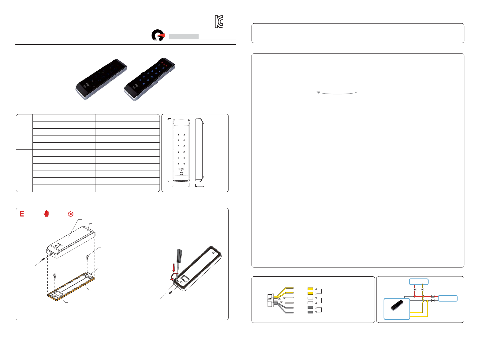
COMPOSITION & SPECIFICATIONS
1
Wired Digital Door Key (RC400)
Mounting screws (4x16)
Mounting template
Connection wire
User’s Manual 1 copy
CompositionSpecification
Power supply
Relay contact capacity
Operating temp
Type
Power consumption
International Protection
GENERAL INFORMATION
3
: Error : Touch : Acon / Set
Screw bolt for
disassembling
/assembling
Connection
wire hole
1EA
2EA
1EA
1EA
DC 12~30V, AC 12~24V
DC30V / 1A
-20℃~50
℃
ISO14443A(Mifare) / 13.56MHz
300mA Under
IP54 (Recommend for Indoor Use)
Use after removing the protective film
※
Upper case
Mounting screws
Lower case
Water proof pad (Silicone rubber)
(When assembling the product,
the water proof pad should
not be twisted)
Water proof pad (Silicone rubber)
Between outside gaps
DIMENSION
2
150
41
Disassembling the upper case
Unfasten the screw bolt,
and use a flat blade (⊖)screwdriver
to disassemble it,
as shown in the figure below.
20
Unit : mm
HOW TO USE
4
1)
[Card Registration]
①②③④ ⇒ ①②③④ ⇒ # ⇒ ① ⇒ # ⇒ Access card (Serial registration is possible) ⇒ # ⇒ * (end)
①②③④ ⇒ ①②③④ ⇒ # ⇒ ① ⇒ # ⇒ Card address(0001~0500) ⇒ Card ⇒ # ⇒ * (end)
Example) Serial registration : if the first address is [0100], next address is [0101] automatically increase.
2)
[Password Registration]
①②③④ ⇒ ①②③④ ⇒ # ⇒ ② ⇒ # ⇒ Password(4digit) ⇒ # ⇒ * (end)
3)
[Card address Delete]
①②③④ ⇒ ①②③④ ⇒ # ⇒ ③ ⇒ # ⇒ Card address (4digit or serial delete) ⇒ # ⇒ * (end)
4)
[Contact Time]
①②③④ ⇒ ①②③④ ⇒ # ⇒ ⑤ ⇒ # ⇒ 01~60 (01sec.~60sec.) ⇒ # ⇒ * (end)
Example) 5’s Setup : 0+5, 20’s Setup : 2+0 (2sec at the time of initial release)
5)
[All Card Delete]
①②③④ ⇒ ①②③④ ⇒ # ⇒ ⑥ ⇒ # (end)
6)
[All Password Delete]
①②③④ ⇒ ①②③④ ⇒ # ⇒ ⑦ ⇒ # (end)
7)
[Card or Password Delete]
Card : ①②③④ ⇒ ①②③④ ⇒ # ⇒ ⑧ ⇒ # ⇒ Access Card (Serial possible) ⇒ # ⇒ * (end)
Password : ①②③④ ⇒ ①②③④ ⇒ # ⇒ ⑧ ⇒ # ⇒ Password ⇒ # (Delete) ⇒ * (end)
8)
[Toggle mode contact change]
①②③④ ⇒ ①②③④ ⇒ # ⇒ ②ⓞ ⇒ # ⇒ Set value (ⓞ~①) ⇒ # ⇒ * (end)
Set value - ⓞ : Normal , ① : Toggle mode (ⓞ at the time of initial release)
9)
[Operation mode setting]
①②③④ ⇒ ①②③④ ⇒ # ⇒ ⑨ ⇒ # ⇒ Set value (ⓞ~①) ⇒ # ⇒ * (end)
Set value - ⓞ:NO, ①: NC (ⓞ at the time of initial release)
10)
[Illumination brightness setting]
①②③④ ⇒ ①②③④ ⇒ # ⇒ ①② ⇒ # ⇒ Set value ⓞ~⑨) ⇒ # ⇒ * (end)
Set value -ⓞ: Illumination OFF, ⑨: The highest degree of brightness (② at the time of initial release)
Set the brightness of the illumination at standby state. In case brightness of the illumination is set at OFF,
when touch pad is pressed, number is displayed.
11)
[System number change]
①②③④ ⇒ ①②③④ ⇒ # ⇒ * ⇒ # ⇒ # ⇒ System number in use ⇒ # ⇒ system number to be changed ⇒ # (end)
System Number: Refers to the number ①②③④ used to set menu.
12)
[System Initialization]
①②③④ ⇒ ①②③④ ⇒ * ⇒ # ⇒ Initialization ⇒ Exit after the LEDs blink. ⇒ (end)
CONTACT TIME
5
Wiring
Yellow
Yellow
White
White
Gray
Gray
Output Contact
External Input
Power
(DC 12~30V, AC 12~24V)
(Serial registration)
6
EM LOCK WIRING
EM Lock
Wired Digital
Door Key
Output Contact
Adapter

D
igital
Wired Door Key
User’s Guide
(RN-RC400)
Patent application
MSIP-CRM-RSN-RN-RC400
NO. 10-1456214
[Card registration] Card type : ISO 14443 (Mifare)
Key in the following digits
1234 → 1234 → # → 1 → #
Access Card (Serial registration is possible)
OR
Card address(0001~1000) → Access Card
# → * (End)
[Note] Serial registration (If the first address will be [0100], next address is [0101] automatically increase.)
[Password registration]
[Open a door]
Password (4 digits) ⇒ # (If more than 4 digit password is entered,
just the last four digits should be identical (right) with your preset
password to open the door.)
Password (4 digits) → #
indicator will appear and
the door key will be operating.
Enter your password (4 digits),
[How to block external input]
password (4 digits) -> *
is blinking twice and
and press the
key.
*
setting is completed.
[Note] Disconnect the input of white line which is external
input. Door is opened and automatically released.
Key in the following digits
1234 → 1234 → # → 2 → #
Insert 4 digit keycode password
# → * (End)
[WARNING & CAUTION]
Fragile
If operator touch the key pad with a
gloved hand, it may cause malfunctioning.
Be careful not to expose it to falling.
 Loading...