


8630
INSTALLATION INSTRUCTIONS
Congratulations – your new Work-Rite load assists are quality products capable of improving the handling and
comfort of your vehicle while under load. As with all products, proper installation is the key to obtaining all of the
benefits your kit is capable of delivering. Please take a few minutes to read through the instructions to identify the
components and learn where and how they are used. It is a good idea to start by comparing the parts in your kit with
the parts list below.
NOTE: IF ANY PARTS ARE MISSING FROM THE KIT, PLEASE CALL 1-800-888-0650.
PLEASE DO NOT CALL OR RETURN THE KIT TO THE DEALER.
Be sure to take all applicable safety precautions during the installation of the kit. The instructions listed in this
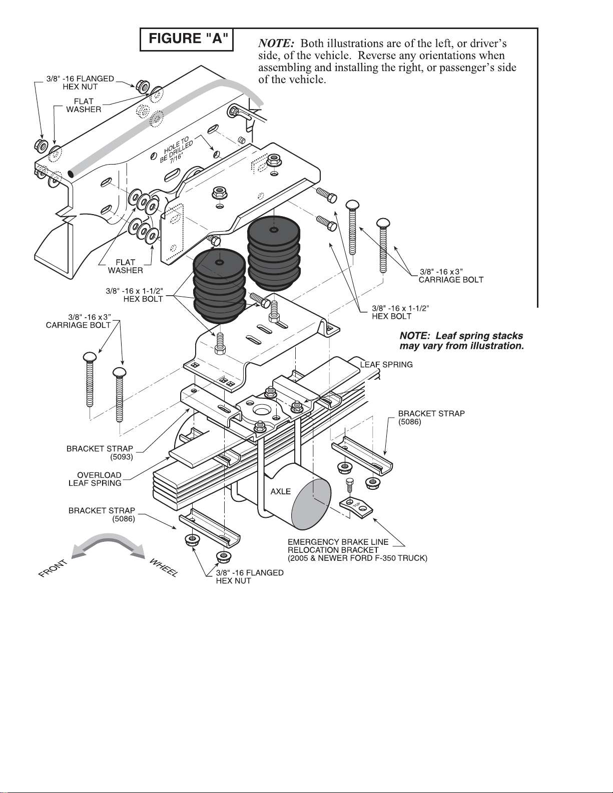
brochure and the illustrations all show the left, or driver’s side of the vehicle. To install the right side assembly simple
follow the same procedures.
STEP 1 - PREPARE THE VEHICLE
With the vehicle is on a solid level surface, chock the front wheels. This vehicle does not have to be raised up to
install the kit. Remove the negative battery cable. This installation assumes that there is no load on the vehicle.
TEP 2 - PREASSEMBLE THE KIT
S
Select two Work-Rite bumpers and an upper bracket from your kit. Fasten the upper bracket to the Work-Rite
bumpers using the 3/8" -16 x 1-1/2" hex bolts inserted into the bottom of the bumpers, through the top hole, and into the
holes in the upper bracket. Secure with a flanged hex nut. See Figure "A".
TEP 3 - PREPARE THE FRAME
S
The frame rail on the driver's side of the vehicle will require the relocation of three items that will interfere with the
upper bracket and air spring. This is accomplished by relocating the existing nuts, bolts, and clips on the frame rail that
fall between the upper bracket flanges.
1.) The emergency brake line clip will be moved toward the rear of the vehicle see Figure "B".
2.) The plastic line harness located on the inside of the frame rail will be moved 2-1/4" toward the rear of the
vehicle. Two 3/8" holes will have to be drilled to relocate the line harness see Figure "B".
3.) The ground strap bolt must be relocated to fall outside the upper bracket flanges see Figure "B". Please note
that the nuts, bolts and clips may be placed in various locations depending upon your specific model.
TEP 4 - ATTACH THE ASSEMBLY TO THE FRAME
S
The three existing slots in the frame rail will be used in addition to one hole drilled in the frame rail to attach the upper
bracket. The slots will have to be enlarged to allow the bolts to pass through. Place the upper bracket on the outside
of the frame rail, aligning the holes in the bracket with the slots in the frame see Figure "A". Using the upper bracket
as a template, mark the hole to be drilled in the frame rail with a center punch. Remove the upper bracket and drill a
hole on the center mark using a 7/16" drill bit. Before drilling, make sure that all electrical, brake, and fuel lines
are cleared from the path of the drill bit. Damaging the lines can be avoided by inserting a piece of wood between
the frame rail and any lines in the path of the drill bit.
PARTS LIST
WORK-RITE BUMPER 1261 4
UPPER BRACKET 5708 2
LOWER BRACKET 5092 2
1/2" BRACKET STRAP 5086 8
1" BRACKET STRAP 5093 2
OPTIONAL SPACER 0013 4
21-0000 08-10
BOLT PACK (A27-760-8630)
3/8" LARGE FLAT WASHER 1 4
3/8" -16 x 3" CARRIAGE BOLT 8
3/8" -16 x 1-1/2" HEX BOLT 1 2
3/8" -16 FLANGED LOCK NUT 1 6
8630
NOTE: On some later model trucks,
the axle u-bolts may have to be trimmed
 Loading...