


PRODUCT SAFETY NOTICE
Congratulations. This vehicle has been equipped with a Firestone air suspension system. This suspension will enhance
the vehicle’s handling when loaded, however, the vehicle’s performance may be altered so that the steering, braking
and handling characteristics of this vehicle may differ from passenger cars and trucks not equipped with this type of
suspension. A vehicle that is loaded will require more distance to stop. A load may alter the vehicle’s center of gravity;
therefore, extreme caution must be used to avoid abrupt maneuvers, sudden sharp turns, and other driving conditions
that could result in loss of control or rollover of the vehicle. Such a loss of control or rollover could result in serious
injury or death. Since the air suspension system is a modification to your vehicle’s suspension, it is recommended that a
professional mechanic perform the installation.
Keep in mind that your vehicle, while loaded, will exhibit different handling characteristics than when unloaded.
Always exercise caution when driving, reduce your speed when noted and fasten your seatbelts. Please keep your
installation instructions and warnings with your vehicle’s owner’s manual for the service life of the vehicle
and provide that information to any subsequent purchasers or others who may use the vehicle with the air
suspension system installed. If you need any additional decals, installation or warning materials, call 1-800-888-0650
for replacement materials.
DEALER/INSTALLER NOTICE
Enclosed with the air suspension system are two safety warning decals which must be attached to the
passenger’s and driver’ sun visor as a supplement to the FMVSS 575.101 warnings if they are in place. The decal
is a safety reminder to the operator and passengers that the vehicle has been modified with an air suspension system.
It is the responsibility of the installer: (1) to affix the warning decals on the sun visors; and, (2) to provide to the end user
the installation instructions and warnings that are included with the air suspension system. The installation instructions
and warnings should be kept with the vehicle owner’s manual in the vehicle’s glove box at all times. It is a condition of
the product warranty that the decals be affixed while the system is installed. If you need additional decals for the vehicle,
please contact Customer Service at 1-800-888-0650 for replacement materials.

W217602518
Before beginning the installation, please read the following instructions and the drivers warning notice thoroughly. The
included warning decal must be placed in the passenger compartment in clear view of all occupants.
NOTE: If any items are missing from this kit or you need assistance with installation, call 1-800-888-0650
for technical assistance. DO NOT return to your dealer.
Start with the vehicle parked on a hard (concrete or asphalt) level surface. Using a measuring tape, measure from the lip
of the wheel rim to the lip of the fender directly above the wheel . Record the measurements below for reference later in
the installation.
Driver’s (Left) rear:_________ Passenger’s (Right) rear:_________
NOTE: Before disassembling your vehicle, compare the parts in the box(s) with those listed in the parts list(s).
REQUIRED TOOLS:
FLOOR JACK
JACK STANDS
VICE GRIPS
MEASURING TAPE
AIR LINE TUBING CUTTER
#2 PHILLIPS SCREW DRIVER
7/32" ALLEN WRENCH
RATCHET
5/16" WRENCH & SOCKET
3/8" WRENCH & SOCKET
1/2" WRENCH & SOCKET
9/16" WRENCH & SOCKET
8MM WRENCH & SOCKET
10MM WRENCH & SOCKET
13MM WRENCH & SOCKET
PART LIST
QTY PART # DESCRIPTION QTY PART # DESCRIPTION
1 21-3582-9378 FULL AIR MANIFOLD (2 CORNER)
1 21-3582-9379 WIRE HARNESS W/KNEEL SWITCH
1 21-3582-9380 FULL AIR ECU
1 21-3582-9008 TUBING 1/4 RED 30 FT
4 21-3582-3414 BAIL CLAMP 3/8-16, 9.5 X 4.25 X 2.5
2 A26-760-9047 140/95MM TUNABLE 369MM
PLASTIC CAP
2 21-3582-5691 DODGE 1500 TOP PLATE
2 21-3582-5690 DODGE 1500 UPPER MOUNT
4 21-3582-5705 AIR ACCESSORY SYSTEM
FRAME BRACKET
1 21-3582-5713 AIR ACCESSORY SYSTEM MOUNT
PLATE
1 21-3582-9127 AIR TANK 3 GALLON
1 24-3582-9285 AIR COMPRESSOR 280C
1 WR1-760-9009 HOSE CUTTER
2 21-3582-5698 DODGE 1500 HEIGHT SENSOR
BRACKET
21-8395 10-10 NAD-37788
1 21-3582-5707 HEIGHT SENSOR LINKAGE BRACKET
1 21-3582-9401 SEALED PRESSURE SWITCH 120/90
4 21-3582-3416 3/8 - 16 X 2.0 THREADED STUD
16 21-3582-3067 3/8-16 FLANGE MAC LOCK NUT
4 21-3582-3022 3/8-16 FLANGE LOCK NUT
1 24-3582-3311 M8 X 1.25 X 15MM HHCS
1 24-3582-3314 M8 FLAT WASHER
4 24-3582-3087 10-32 X 1” MACHINE SCREW
8 24-3582-3086 3/16 FLAT WASHER
4 21-3582-3088 10-32 UNF NYLON LOCK NUT
2 21-3582-3424 1/4-20 X 3/4 BUTTON HEAD BOLT
2 21-3582-3055 04 X 02 MALE CONNECTOR
3 21-3582-3128 1/8 NPT SWIVEL ELBOW 1/4 TUBE
1 21-3582-3031 1/4 PTC ELBOW FITTING
1 21-3582-3269 1/4 NPT PLUG
2 21-3582-3032 INFLATION VALVE PTC
1 21-3582-3066 COMPRESSOR TEE FITTING
3 21-3582-3025 1/4 PUSH TO CONNECT TEE

HEIGHT SENSOR PACK
QTY PART # DESCRIPTION QTY PART # DESCRIPTION
1 28-3582-0111 LEFT HEIGHT SENSOR 50MM ARM
1 28-3582-0112 RIGHT HEIGHT SENSOR 50MM ARM
2 24-3582-3310 M6 X 1.00 X 12MM HHCS
2 24-3582-3263 M6 X 1MM PITCH NYLON LOCK NUT
4 24-3582-3260 M5 X 8 MACHINE SCREW
2 24-3582-3265 M5 X .8MM ALL THREAD
4 24-3582-3266 5MM SENSOR LINKAGE
4 24-3582-3264 M5 X .8MM PITCH JAM NUT
8 21-3582-3421 10-16 X 3/4 SELF TAPPING SCREW
4 24-3582-3262 M5 X .8MM PITCH NYLON LOCK NUT
8 24-3582-3318 M5 FLAT WASHER
AUTO LEVELING PACK
QTY PART # DESCRIPTION QTY PART # DESCRIPTION
1 21-3582-5325 DODGE 1500 KNEEL SWITCH BRACKET
1 A24-760-7543 IGN LINE FUSE CIRCUIT TAP PACK
1 21-3582-9361 SEALED RELAY
2 21-3582-3420 10-16 X 1/2 SELF TAPPING SCREW
2 21-3582-3419 4-40 UNC-2A X 5/8 MACHINE SCREW
2 21-3582-3418 4-40 NYLON INSERT HEX NUT
1 24-3582-3086 3/16 FLAT WASHER
1 21-3582-3088 10-32 UNF NYLON LOCK NUT
1 24-3582-3093 10-32 X 3/4 MACHINE SCREW
2 21-3582-3425 1/4-20 X 1-3/4 HEX BOLT
2 21-3582-3407 1/4-20 UNC NYLON LOCK NUT
1 21-3582-0864 1/4 FLAT WASHER
1 21-3582-9398 10 PSI PRESSURE RETENTION VALVE
DODGE 1500 CONVERSION PACK
QTY PART # DESCRIPTION QTY PART # DESCRIPTION
4 21-3582-0899 THERMAL SLEEVE
15 21-3582-9036 TIE STRAP NYLON- RED
2 21-3582-9403 DECAL DODGE WARNING
1 21-3582-8395 INSTRUCTION MANUAL 2518
1 21-3582-9372 DECAL RIDE-RITE

STEP 1: PREPARE THE VEHICLE
Place the vehicle on a flat surface. Measure and record the ride height
on Page 2. The most accurate way to measure this height is to measure
from the lip of the wheel rim to the fender directly above the wheel
(Figure “A”).
Raise the vehicle, or the rear of the vehicle, to allow the suspension to relax and remove the wheels. Remove the fender liner on both
sides of the vehicle.
Figure “A”
STEP 2: REMOVE STOCK COIL SPRINGS
Support the rear axle with axle stands rated for the vehicle’s weight.
Remove the lower shock bolt on both sides of the vehicle. See Figure
“B”. The shocks can be completely removed for clearance during
installation, but it is not required.
Allow the axle to extend completely and remove the coil springs and
upper mounts on both sides of the vehicle. See Figure “C”.
STEP 3: PREASSEMBLE THE AIR SPRINGS
Install the air fitting on each air spring. Tighten the fitting to engage
the nylon ring, then tighten and additional 1/2 turn. Install the threaded
studs to the top of the air spring. Slide the upper mount (5690) over
the studs so the flat surface is touching the top of the air spring. Set
the preassembled air springs aside.
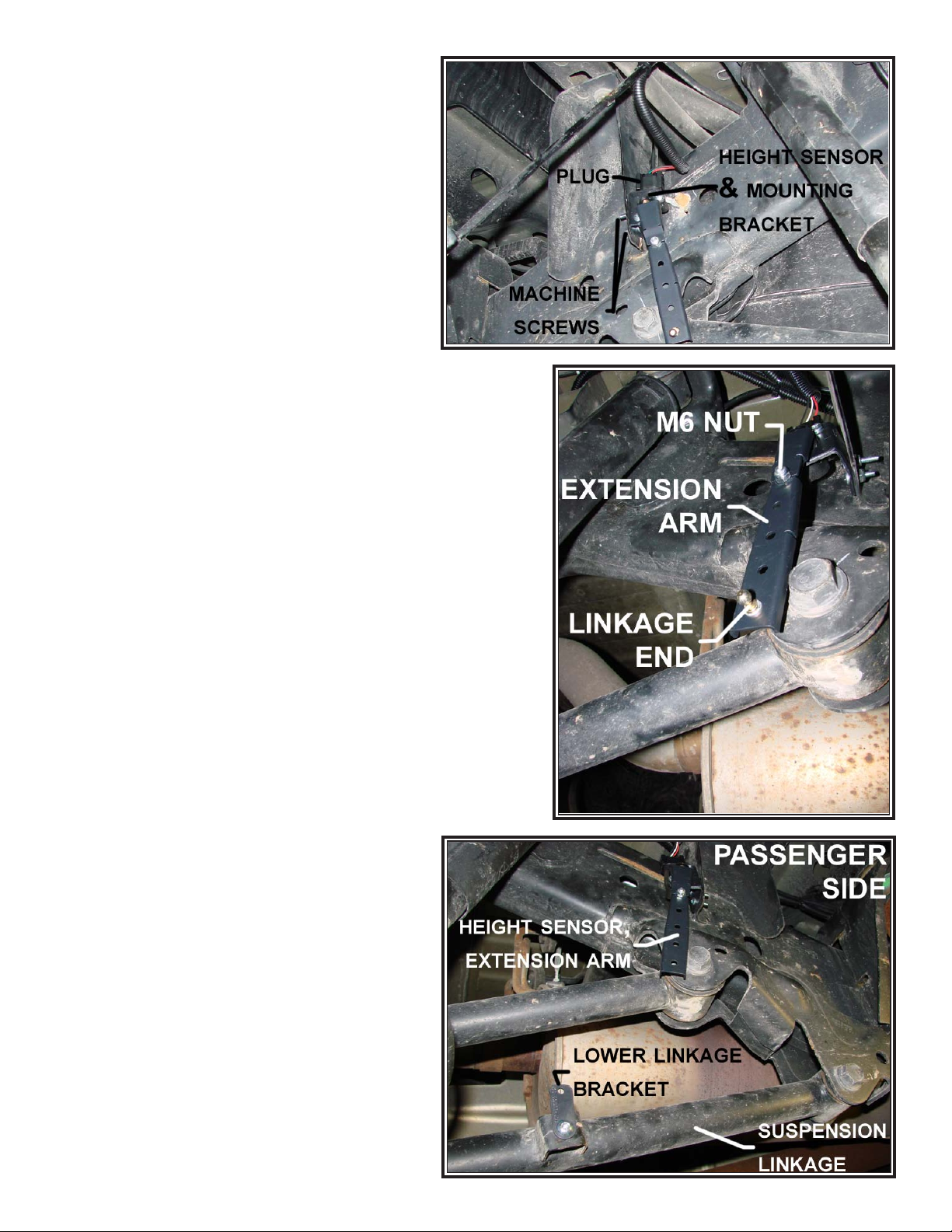
STEP 4: MOUNT THE HEIGHT SENSORS
Attach the height sensor extension arm to the height sensor using a
M6-1.0 X 12mm bolt and M6 nylock. Attach one M5 sensor linkage with
the ball towards the outside and in the hole farthest from the height
sensor. Use a M5 nylock to secure to the arm. See Figure “F”.
On the passenger side, use the provided M8-1.25 X 15MM bolt and M8 washer to mount the lower linkage bracket
to the vehicle’s lower suspension linkage. There is an unused weld nut on the lower arm forward of the axle. The bracket
should point up once installed. Attach one M5 sensor linkage to the other hole in the bracket so the ball faces inboard.
Secure with a M5 nylock nut. See Figure “F”.
On the driver side, remove the M8 bolt that holds the emergency brake cable bracket. The bracket should be installed
between the weld nut and the brake cable bracket. Install the lower linkage bracket and reinstall. Attach an M5 sensor
linkage and secure with an M5 nylock nut. See Figure “G”.
The height sensors are marked L (left) and R (right). When mounted, the electrical plug should face up and the arm
should rotate towards the rear of the vehicle. Brackets should have the open end facing towards the rear of the vehicle and
Figure “C”Figure “B”
be parallel with the ground. The bracket will angle the
height sensor arm inboard to allow the arm to swing
freely throughout the suspension travel. Ensure the
extension arm does not interfere with the shock.
FOR CREW CAB: The height sensor brackets should
be installed just behind the bed mount brackets
approximately halfway up the frame. This should be
above the front vehicle suspension mount.
FOR QUAD CAB/REGULAR CAB: The height sensor
brackets should be installed above the front vehicle
suspension mount, approximately halfway up the
frame. This is about 10 inches back from the bed
mount bracket.
While holding the height sensor bracket in place, use
(2) 10-16 x 3/4 self tapping screws to attach the height
sensor bracket to the vehicle on each side. NOTE: 7/32"
holes and machine screws (not provided) can be used
in place of the self tapping screws.
Attach the height sensor to the installed bracket using (2) M5-0.8
X 8mm machine screws on each side. See Figure “D”.
Figure “D”
STEP 5: INSTALL THE AIR SPRINGS
The bottom of the air spring assembly has a threaded hole that must
face the rear of the vehicle and the air fitting on the top should face
the front of the vehicle. Place the air spring assembly on the lower
axle mount. Using the 1/4"-20 x 3/4" button head screws provided,
secure the bottom of the air spring assembly to the lower mount. See
Figure “H”.
Place the top plate on the top side of the upper mount. Unroll the
air spring, by pushing the top of the air spring up, until the air spring
assembly reaches the upper mount on the vehicle. Place the top plate
above the vehicle’s upper spring seat by aligning the top plate to accept
the threaded studs from the air spring assembly. Hand tighten the 3/8"16 nuts (serrated face) to the top plate. DO NOT ALLOW THE AIR
SPRING SLEEVE TO TWIST. Once the air fitting is correctly aligned
towards the front of the vehicle and you have ensured the sleeve is not
twisted, tighten the 3/8"-16 nuts See Figure “H”.
Reinstall the shocks on both sides of the vehicle.
Figure “E”
STEP 6: PREASSEMBLE THE COMPRESSOR, VALVE
BLOCK, AND ECU MOUNT
See Figure “U” for bracket layout. The mounting plate for the compressor, valve block, and ECU has predrilled holes to accept each
component. All components that are mounted to
the plate should have the head of the bolts on the
back side of the plate for clearance.
The compressor mounts in the lower left side with
the intake pointing left. Use four 10-32 X 1" machine
screws with washers and nylock nuts to mount to the
plate. Attach the compressor tee fitting to the check
valve on the output side of the compressor. Attach the
pressure switch to the compressor tee. See Figure
“I”. The ECU mounts directly above the compressor
with two, 4-40 X 5/8” machine screws and nylock nuts.
See Figure “I”.
Before mounting the block, install the 1/8 NPT
straight air fittings into the ports labeled ‘LR’ and ‘RR’.
Tighten to engage the orange thread sealant. Install
the 1/8 NPT elbow into the port marked ‘IN’. Handtighten, then turn an additional 1/2 turn with a wrench.
The valve block should be oriented so that the exhaust
port points to the right and the inlet is down. Use the
1/4"-20 X 1-3/4" bolts with washers and nylock nuts
to secure the block in place. See Figure “J”.
Figure “F”

Attach the relay to the plate where it will be accessible
in the future. Secure using one 10-32 X 3/4" machine screw
and nylock nut.
STEP 7: MOUNT THE SYSTEM PLATE AND
TANK TO THE VEHICLE
Select the air tank from the kit and install the 1/4 NPT
plug into one end and the 1/4 NPT elbow fitting into the
other end. Tighten the fittings to engage the orange thread
sealant. Mount the tank to two frame brackets using four,
3/8"-16 flange nuts. See Figure “K”.
Mount the tank assembly to the passenger side frame
rail using two bail clamps and four 3/8"-16 flange nuts.
It should be located on the outside of the frame rail just
forward of the fender well. See Figure “K”.
Mount the preassembled system plate to two frame
brackets using four 3/8"-16 flange nuts. Mount the system
plate assembly to the frame using two bail clamps and four
3/8"-16 flange nuts. The plate should be on the outside
of the frame rail, just forward of the tank assembly. See
Figure “I” & “J”.
NOTE: It is important that the system plate assembly is located on
the passenger side frame rail.
STEP 8: INSTALL THE WIRE HARNESS
Uncoil the wire harness and locate the 16-pin ECU connector. Route
the portion of the harness with the two height sensor connectors (6-pin)
along the frame rail towards the rear of the vehicle. Route the driver
side height sensor connector through the hollow cross-member under
the bed to the other side of the vehicle. Once the connections have
been made at the height sensors, peel back the wire loom to expose
the LED for each side. Ensure the LED is easily visible. See Figure “L”.
Make the connection at the relay. Ground the compressor lug to a
suitable location on the chassis. Attach the red wire (male spade) from
the relay to the red wire (female spade) on the compressor. Attach the
blue wire from the relay to one side of the pressure switch. Attach the
black wire (female spade) in the harness to the other side of the pressure switch. NOTE: DO NOT INSTALL THE 8-PIN PLUG FOR THE
VALVE BLOCK AT THIS TIME.
Route the remaining wire harness forward along the frame rail and
into the engine compartment, staying as far away as possible from
potential heat sources. Run the wire across the back of the engine
compartment, securing the loom to firewall. See Figure “M”.
Once the harness is on the driver’s side by the fuse
box and battery, route the three wires for the kneel switch
through the firewall. Crimp the provided fuse tap to the
yellow wire.
NOTE: DO NOT COMPLETE THE CONNECTION TO THE
FUSE BOX OR THE BATTERY AT THIS TIME.
In the cabin, route the three wires and loom to the final
location of the kneel switch. The location of the switch
should be easily seen, but not accidentally hit. The switch
will glow red when the vehicle is kneeled. During normal
operation, the switch will not be illuminated. A bracket and
self-tapping screws, 10-16 X 1/2, have been provided to
mount the switch, but they do not need to be used. NOTE:
A 20MM hole will need to be drilled for the switch if the
bracket is not used. After the switch is mounted, connect
the wires to the male spade terminals on the back of the
kneel switch. See Figure “O”.
Figure “G”
Figure “H”
Figure “I”
STEP 9: AIR LINE INSTALLATION
DO NOT FOLD OR KINK THE TUBING. The tubing should
have square cuts using the supplied tubing cutter. DO NOT
 Loading...