


User Manual
RISHABH Young /iYoung
Multimeter


600V
OFF
NCV
10A
0.4A
1

2
1. Safety Features and Precautions ...................
2. Initial Start-up ...................................................
3. Selecting Measuring Functions & Ranges ....
3.1 Measuring Function Selection............................
3.2 Automatic Measuring Range Selection..............
3.3 Manual Measuring Range Selection..................
4. Liquid Crystal Display ....................................
4.1 Digital Display ...................................................
4.2 Display with Backlit(optional).............................
5.0 Buzzer ..............................................................
6.0 Measurement Value Storage ” HOLD”............
7.0 REL - Relative value measurement ...............
8.0 Voltage Measurement .....................................
9.0 Current Measurement ( only).................iYoung
9.1 AC Measurement with (Clip-on) C.T. ................
10.0 Diode Testing & Continuity Measurement ....
10.1 Diode Testing ....................................................
10.2 Continuity Testing .............................................
11.0 Resistance Measurement ...............................
12.0 Capacitance Measurement ............................
13.0 Frequency & Duty cycle Measurement ........
13.1 Frequency Measurement .................................
13.2 Duty Cycle Measurement .................................
14.0 Non Contact Voltage (NCV) detection...............
15.0 Specifications .................................................
16.0 Maintenance ....................................................
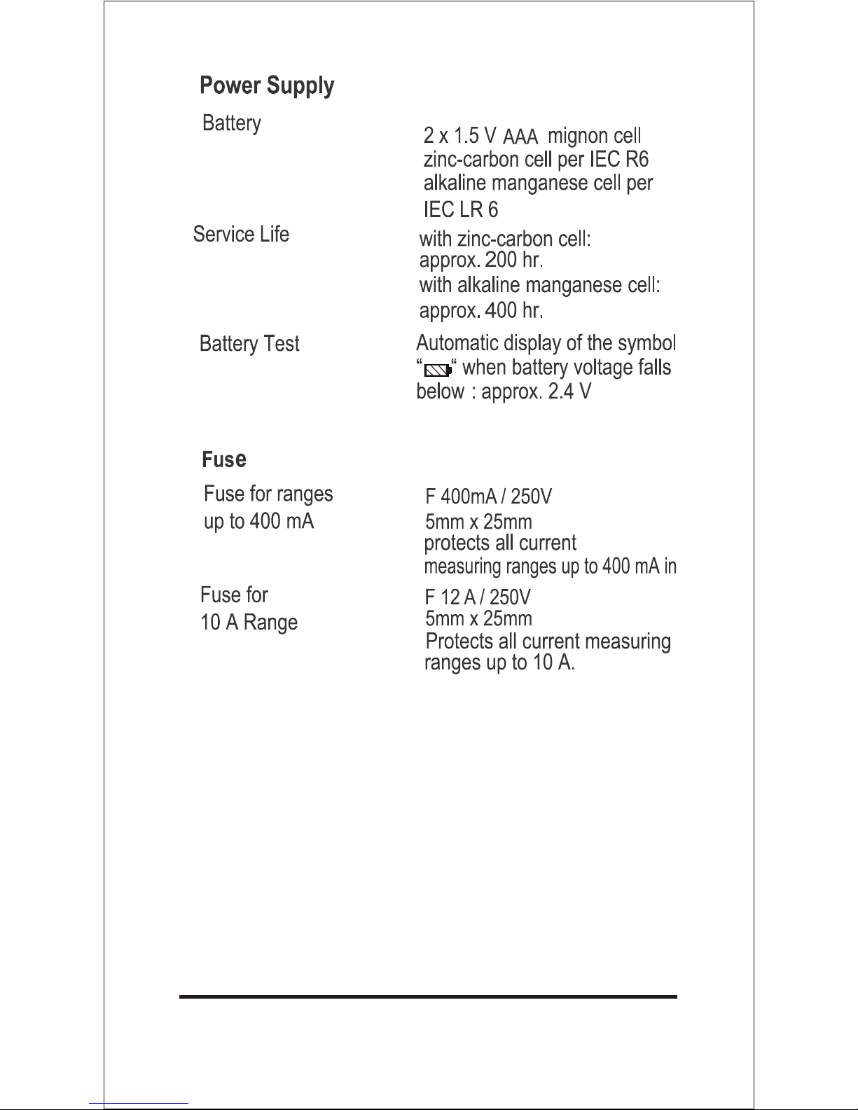
16.1 Battery ..............................................................
16.2 Fuses ................................................................
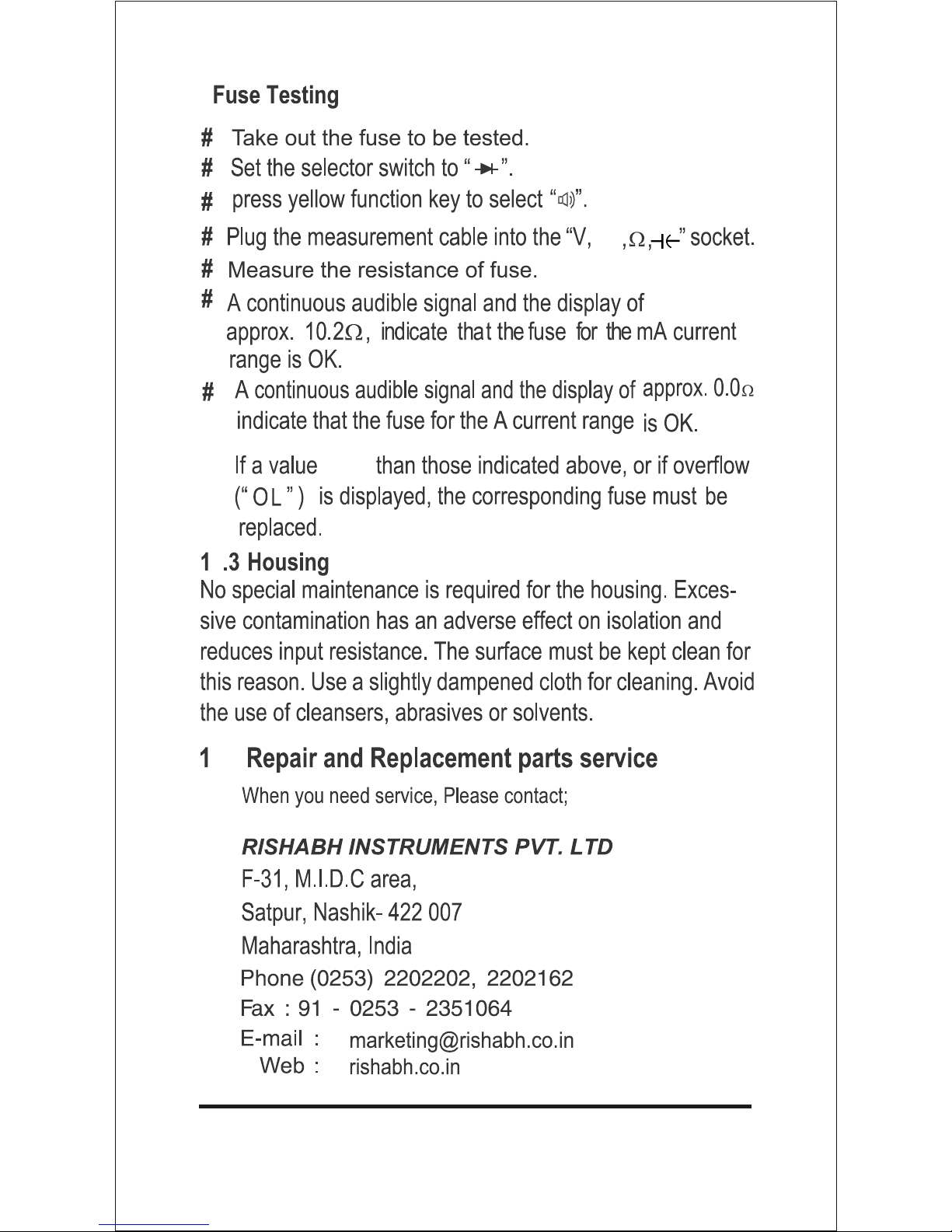
16.3 Housing .............................................................
17.0 Repair and Replacement parts service .........
4
6
7
7
8
8
9
9
9
10
10
10
10
12
13
14
14
15
16
17
19
19
19
20
21
26
26
27
28
28
3

4

Meaning of the symbols
Warning of a danger point
(Attention, refer to the user manual)
Earth (ground) terminal.
Double or reinforced insulation
5
6

7

AC
8
Hz
%
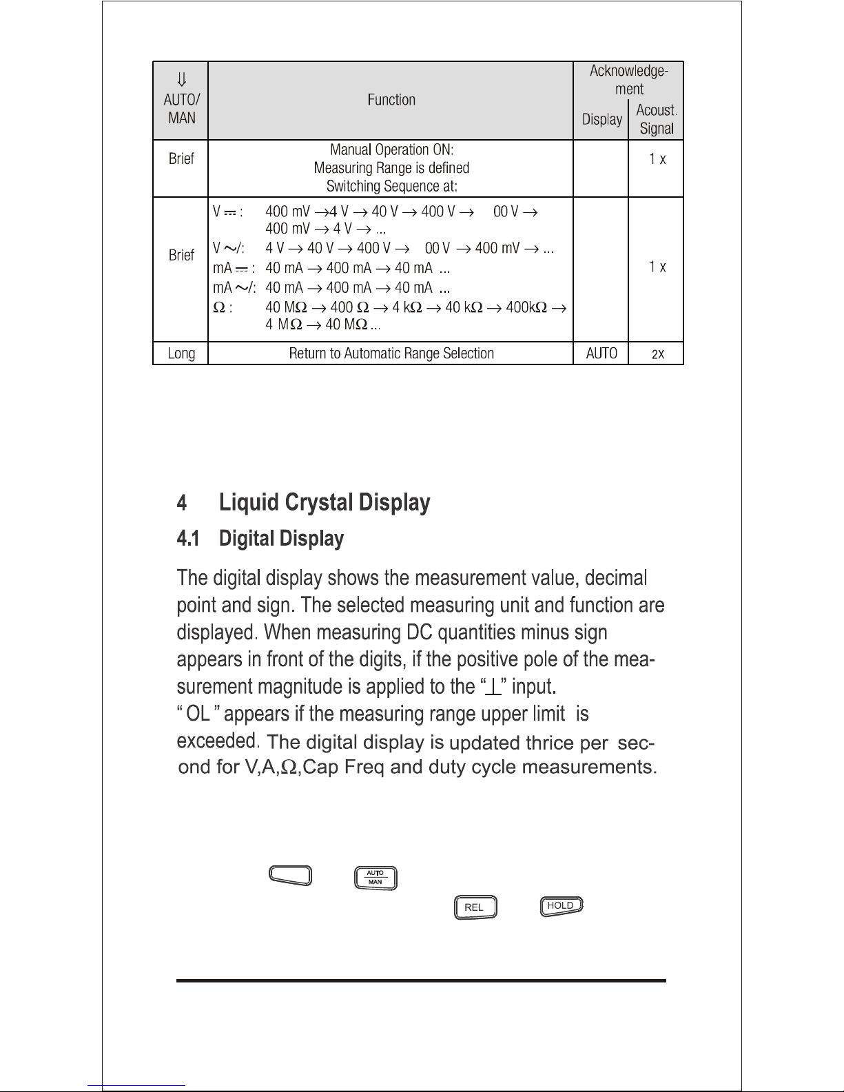
Note : For Frequency (Hz), Duty cycle (%)
and Capacitance (F) measuring range is always Auto.
No manual range selection is possible.
4.2 Display with Backlight (Optional)
By pressing
and
keys simultaneously backlight
keys simultaneously backlight can be switched ON.
can be switched OFF and by pressing
9
and
6
6

When measuring AC Voltage > 750 V, DC Voltage > 1000 V,
AC/DC mA > 400.0 mA, AC/DC A > 10 A, the buzzer will
keep sounding as the overload warning.
Approximate 1 minute before the meter is auto power off,
the buzzer will raise constantly 5 sounds to warning.
Before the meter is power off, the buzzer will raise one long
sound to warn the user.
.
10

11
600V
12A
400mA

12
on

13
600V
12A
400mA
mA
A

10 Diode Testing & Continuity Measurement
10.1 Diode Testing
14
600V
12A
400mA
OFF
NCV
OFF
NCV
9.1.1
9.1.2

10.2 Continuity Testing
15
600V
12A
400mA

11 Resistance Measurement
16
600V
12A
400mA
600V
12A
400mA

Deleting Zero Adjustment
Again press REL key.
or
Activate the function selector switch.
or
Switch the Multimeter off.
17
600V
12A
400mA

18

13 Frequency & Duty Cycle Measurement
13.1 Frequency Measurement
Set the function selector switch to VAC and press yellow
function key as shown on page 20.
The frequency measurement mode is activated. “Hz” symbol
is displayed on the LCD. The digital display is expanded to
9999 digits. Only the auto mode is possible, no manual
range is possible.
13.2 Duty Cycle Measurement
With duty cycle measurement, we can determine the ratio
of pulse duration to cycle time of recurring square wave
signals. The duty cycle that is the percentage pulse duration
of signal is displayed on LCD i.e.
Duty cycle (%) =
pulse duration
cycle duration
X 100
Note : The applied frequency must remain constant during
the duty cycle measurement.
Set the function selector switch to VAC and press yellow
function key twice as shown on page 20.
The Duty cycle (%) mode is activated. “%” symbol is
displayed on LCD.
15.
19
b)

14 Non Contact Voltage (NCV) detection.
Connections are made the same way as for Voltage
measurement
measuring range for duty cycle and maximum allowable
voltage can be found in chapter “Specifications”.
V~
Press yellow
Press yellow
Press yellow
Press yellow
function key
function key
function key
function key
20
600V
10A
400mA
Non contact voltage detection allows detection of AC voltage
from >120V 50Hz/60 Hz simply keeping the display side of
Multimeter near the voltage carrying conductor without safety
cover. Presence of voltage is indicated by the beep sound. To
select NCV function keep the knob on NCV. In this function LCD
will be OFF.
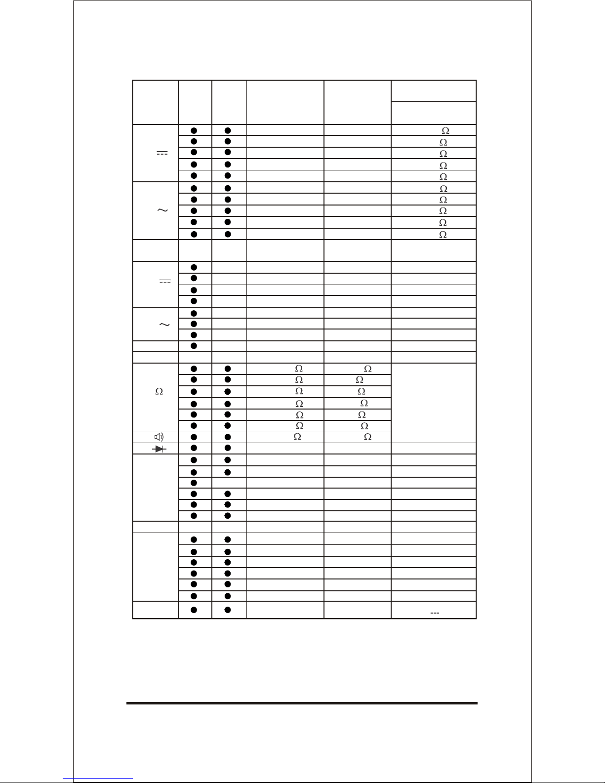
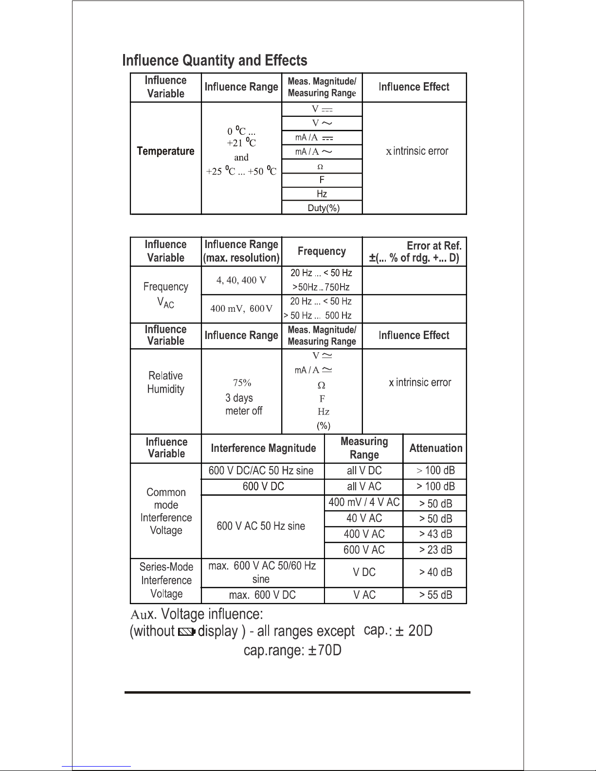
15 Specifications
1) 10A for 5min or Max 12A for 30sec
2) Indication for frequency measurement expanded to 9999 D
21
Meas.
Function
iYoung
Young
Measuring
Range
Resolution
Input Impedance
400.0mV
4.000V
40.00V
400.0V
600V
400.0mV
4.000V
40.00V
400.0V
600V
100µV
1mV
10mV
100mV
1V
100µV
1mV
10mV
100mV
1V
40.00mA
400.0mA
1)
10.00A
40.00mA
400.0mA
1)
4.00A
10µA
100µA
10mA
10µA
100µA
1mA
400.0
4.000k
40.00k
400.0k
4.000M
40.00M
400.0
1.000V
5.000nF
50.00nF
500.0nF
5.000µF
50.00µF
200.0µF
100m
1
10
100
1k
10k
100m
1mV
1pF
10pF
100pF
1nF
10nF
100nF
9.999Hz
99.99Hz
999.9Hz
9.999kHz
99.99kHz
500.0kHz
0.001Hz
0.01Hz
0.1Hz
1Hz
10Hz
100Hz
2.0...98.0% 0.1%
V(AC) / V(DC)
>20M
11M
10M
10M
10M
11M
11M
10M
10M
10M
Approx. Voltage drop
at max. meas. current
450mV
4.2V
750mV
450mV
4.2V
45mV
Open-circuit voltage
approx 0.45V
approx 1V
9Hz
9Hz
9Hz
9Hz
9Hz
9Hz
f
min
F
Hz
%
V
V
A
A
2)
1)
10.00A
10mA
750mV
1)
4.00A
1mA
450mV

0
0
1) At 0 C... + 50 C
2) With zero adjustmet “REL”.
3) Time required for measurement approximately 60 seconds.
4) Specified Accuracy is valid as of 5% of the measuring range for 400.0mV AC
5) For Hz & Duty Cycle measurement, select proper range for VAC function.
22
6) At input, 5Vrms, Square wave, Bipolar inputs+
40.00mA
400.0mA
10.00A
40.00mA
400.0mA
10.00A
400.0
4.000k
40.00k
400.0k
4.000M
40.00M
400.0
1.000V
5.000nF
50.00nF
500.0nF
5.000 Fµ
50.00 Fµ
200.0 Fµ
9.999Hz
99.99Hz
999.9Hz
9.999kHz
99.99kHz
500.0kHz
2.0...98.0%
1.5+9
2+5
1.5+9
2.5+9
1+5
2+5
2.5+5
Acoustic signal for
0...< 60 (approx)
2.5+5
2)
5+40
2)
3+10
2)
1.5+10
2)
2+10
3)
5+40
0.5+5
10Hz...1kHz : +5D
1kHz...10kHz : +5D/kHz
Continuous
Continuous
480mA
480mA
500V
DC/AC
rms
5 min
500V
DC/AC
rms
5 min
Measuring
Range
400.0mV
4.000V
40.00V
400.0V
600V
400.0mV
4.000V
40.00V
400.0V
600V
Digital display inherent
deviation at
reference conditions
+ (...% of rdg + ...digits)
1+9
2+9
1.5+9
Overload capacity
Overload value
Overload
duration
1050V(DC)
1050V(AC)
rms
Continuous
Continuous
Meas.
Function
F
5) 6)
Hz
%
V
V
A
A
1)
4)
4.000A
12A
30s
4.000A
12A
30s
1.5+5
500V
DC/AC
rms
5 min
5) 6)

23
24
Intrinsic
3.5 + 3
3.5 + 3
1
1.5
/10K
25

6
6
26
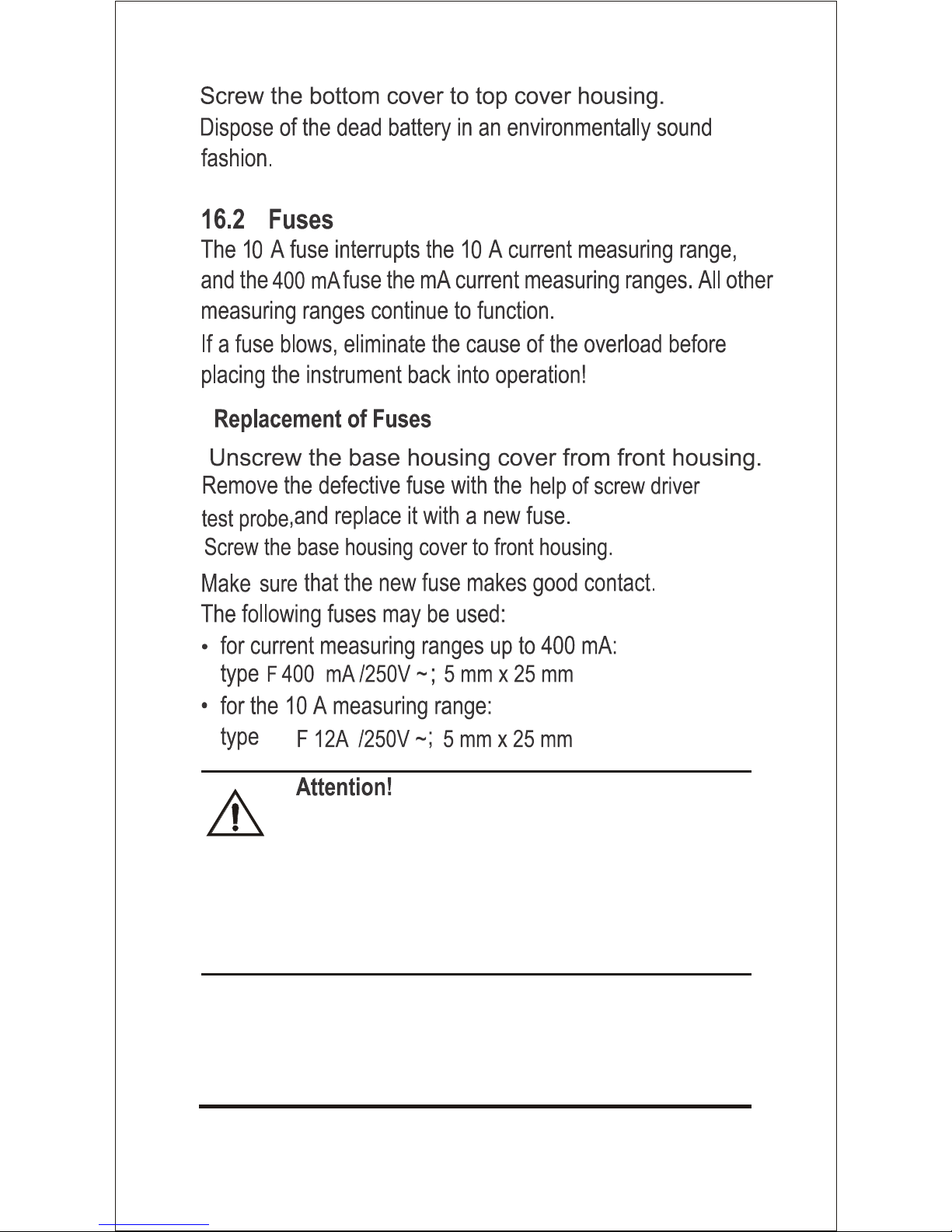
Be absolutely certain that only the specified fuses
as above are used. The use of fuse with different
specifications may place the operator, the system
& measuring instrument in danger. The use of
repaired fuses or short-circuting of the fuse holder
is prohibited.
27
6
28
7
mA
more


www.rishabh.co.in
Printed in India, Subject to change without Notice
Factory: F-31, MIDC, Satpur, Nashik-422 007 India
Phone(0253) 2202202, 2202162
Fax : 91 - 0253 - 2351064, 2202302
E-mail : International: exp.marketing@rishabh.co.in
RISHABH INSTRUMENTS PVT. LTD.
Item Code: DMAN-00IM-0580Rev A: 18/12/2016
India: marketing@rishabh.co.in
 Loading...