

Page 1
RISH Master 3440i/3440iDL 0.2S
RISH Master 3440i/3440iDL 0.2S
Operating Manual
as per IEC62053-22
Page 2

Page 3

Section
Touch Screen Digital Multi-Function Meter
Installation & Operating Instructions
Contents
1. Introduction
2. Measurement Reading Screens
3. Programming
3.1 Password Protection
3.2 Menu selection
3.2.1 System Parameter selection screen
3.2.1.1 System type
3.2.1.2 Potential transformer Primary value
3.2.1.3 Potential transformer secondary value
3.2.1.4 Current transformer Primary value
3.2.1.5 Current transformer Secondary value
3.2.1.7 Demand integration time
3.2.1.8 Auto Scrolling
3.2.1.9 Low current noise cutoff
3.2.1.11 Energy resolution
3.2.1.12 Energy digit reset count
3.1.1 Change Password
INDEX
DMAN-00IM-0683_Rev.C 08/2018
3.2.1.13 Energy Update Rate
3.2.1.6 System Frequency
3.2.1.10 Number of Poles
3.2.1.14 Meter Version
1
Page 4

3.2.4.1 Relay 1 output selection menu
3.2.4.1.1 Pulse output
3.2.4.1.1.1 Assignment of Energy to Pulse (Relay 1)
3.2.4.1.1.2 Pulse Duration Selection
3.2.4.1.1.3 Pulse Rate
3.2.4.1.2 Limit output
3.2.4.1.2.1 Assignment of Limit Output1 to Parameter
3.2.4.1.2.5 Limit Conguration
3.2.4.1.2.6 Trip point selection
3.2.4.1.2.7 Hysteresis selection
3.2.4.1.2.8 Energizing delay time
3.2.4.1.2.9 De-energizing delay time
3.2.4 Output Option selection screen (menu)
3.2.3.1 Resetting Parameter
3.2.3 Reset Parameter selection screen
3.2.2 Communication Parameter selection screen
3.2.2.1.1 Address Setting
3.2.2.1.2 RS 485 Baud rate
3.2.2.1.3 RS 485 Parity selection
3.2.2.1 Modbus Setting
3.2.2.2 Ethernet Setting
3.2.2.2.1 IP Address Setting
3.2.2.2.2 Subnet Mask Setting
3.2.2.2.3 Default Gateway Setting
3.2.2.2.4 Server Port Setting
3.2.4.1.2.2 Energy Count Conguration
3.2.4.1.2.3 Energy Trip point
3.2.4.1.2.4 Energy Count On Delay
2
Page 5

3.2.4.2 Relay 2 output selection menu
3.2.4.3 Parameter setting for Analog Output-1
3.2.4.4 Parameter setting for Analog Output-2
3.2.8 Brightness & Contrast
3.2.4.1.4 RTC Relay
3.2.4.1.4.1 Weekdays Selection
3.2.4.1.4.2 Timer Conguration
3.2.4.1.4.3 On Time
3.2.4.1.4.4 Off Time
3.2.5.1 Event Based Datalog
3.2.5.2.1 Status
3.2.5 Datalogging Option Selection
3.2.5.2 Time Based Datalog
3.2.5.3 Load Prole Datalog
3.2.5.2.2 Time Interval
3.2.5.2.3 Parameters
3.2.6.1 Sag Threshold
3.2.6 Power Quality Settings
3.2.6.2 Swell Threshold
3.2.6.3 Sag & Swell Hysteresis
3.2.6.4 Overcurrent Threshold
3.2.6.5 Overcurrent Hysteresis
3.2.7 Date & Time Settings
3.2.4.1.3 Timer
3.2.4.1.3.1 Number of Cycles
3.2.4.1.3.2 Timer Conguration
3.2.4.1.3.3 On Delay
3.2.4.1.3.4 Off Delay
3
Page 6

13.
Specication
11. Installation
11.1 EMC Installation Requirements
11.2
Case Dimensions and Panel Cut-out
11.3
Wiring
11.4 Auxiliary Supply
11.5 Fusing
11.6 Earth / Ground Connections
12.
Connection Diagrams
14.
Connection for Optional Pulse output / RS 485 /Analog Output / Ethernet
10.
Phasor Diagram
Relay Output
9.
Pulse output
9.1
Limit switch
9.2
7. Analog Output
6.3 Number of Interruption
6.2
On - Hour.
6.1
Run - Hour.
5. Phase Rotation Error screen.
4. Touch screen calibration.
6. Run Hr, On Hr & No. of Interruptions
Timer Output
9.3
PQ Measurement
8
3.2.9 RGB Color Code
3.2.10 Factory Reset
4
Page 7
1. Introduction
This instrument is a panel mounted 96 x 96mm DIN Quadratic Digital metering system for the
measurement of important electrical parameters like AC voltage, AC Current, Frequency,
Power, Energy(Active / Reactive / Apparent) . The instrument integrates accurate measurement
of technology (All Voltage & Current measurements are True RMS upto 15th Harmonic) with
320x240 Pixels touch screen TFT LCD display.
This instrument can be congured and programmed at site for the following: PT Primary, PT
Secondary, CT Primary, CT Secondary (5A or1A) and 3 phase 3W or 3 Phase 4W system.
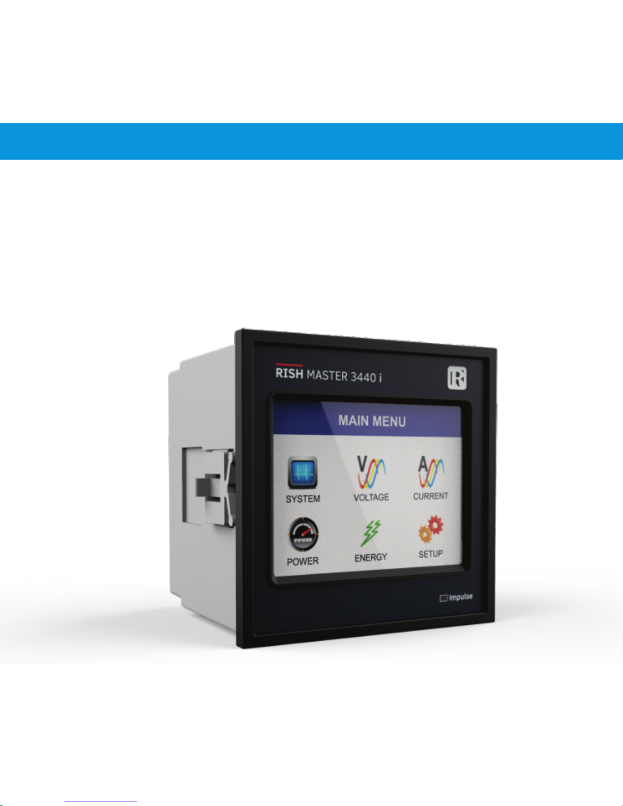
The front panel has a 3.5” Touch Screen through which the user can move across the available
measurement readings, reset the energy, Min/Max (System Voltage and System Current) and
congure the product settings.
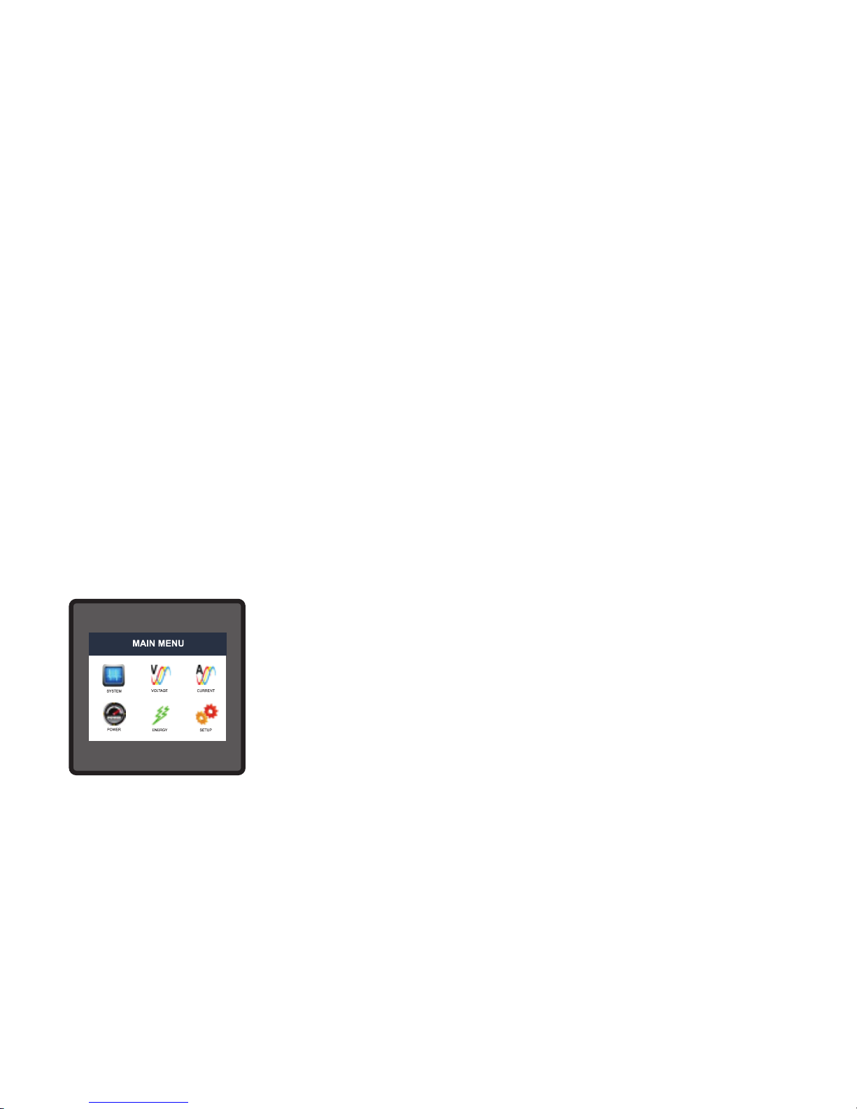
Main menu is divided into 6 submenus. Each submenu contains a list
of options. By touching the icons on main menu, submenus can be
accessed. System submenu can be used to access RTC, harmonics,
Power Quality events and other system parameters like system
power, min, max voltage and current, THD, run hour, on hour and
number of interruptions. Voltage, current and power submenu contain
measurement of basic elecrical parameters. Energy submenu gives
the total energy and Setup submenu can be used for complete meter
settings.
5
Page 8

TABLE 1:Measurement Parameters for both models
System Voltage
System Current
Frequency
Voltage VL1-N(4wire only)
Voltage VL2-N(4wire only)
Voltage VL3-N(4wire only)
Voltage VL1-L2
Voltage VL2-L3
Voltage VL3-L1
Current L1
Current L2
Current L3
Volts
Amps
Hz
Volts
Volts
Volts
Volts
Volts
Volts
Amps
Amps
Neutral Current ( 4 wire only )
Amps
Amps
Active Import Energy (8 Digit resolution)
kWh
kWh
Active Export Energy (8 Digit resolution)
Active Power (System / Phase (4 wire only) )
Reactive Power (System / Phase (4 wire only))
Apparent Power (System / Phase (4 wire only))
Power Factor (System / Phase (4 wire only))
Phase Angle ( Phase(4 wire only))
Kwatts
KVAr
KVA
Degree
kVArh
Inductive Reactive Energy (8 Digit resolution)
kVArh
Capacitive Reactive Energy (8 Digit resolution)
kVAh
Apparent Energy (8 Digit resolution)
( for 3 / 4 wire)
( for 3 / 4 wire)
( for 3 / 4 wire)
( for 3 / 4 wire)
( for 3 / 4 wire)
( for 3 / 4 wire)
Units of
Measurement
Date,Time
RTC
%
Individual Harmonics V
Individual Harmonics I
%
RM3440i
RM3440iDL
Sag, Swell & Overcurrent Events
-
Measured Parameters
6
Page 9

*Note : THD Parameters are L-N in case of 3P 4W & L-L in case of 3P 3W .
KW Import Demand
KVAr Cap. Demand
KW Export Demand
KVAr Ind. Demand
Max Current Demand
Max kVA Demand
Max KW Import Demand
Max KW Export Demand
Max KVAr Ind. Demand
Max KVAr Cap. Demand
Run Hour
On Hour
Number of Interruptions
Phase Reversal Indication ( 4 wire only )
KW
KW
Amps
KVA
KW
KW
KW
KW
KW
KW
Hours
Hours
Counts
Amps
Current Demand
KVA Demand
KVA
I1 THD
I2 THD
V1 THD*
V2 THD*
V3 THD*
%
I3 THD
System Voltage THD
System Current THD
%
%
%
%
%
%
%
( for 3 / 4 wire)
( for 3 / 4 wire)
( for 3 / 4 wire)
( for 3 / 4 wire)
( for 3 / 4 wire)
( for 3 / 4 wire)
count,sec,sec
Timer1 No. of Cycles, ON, OFF delay
Timer2 No. of Cycles, ON, OFF delay
Measured Parameters
Units of
Measurement
count,sec,sec
TABLE 1:Continued...
RM3440i
RM3440iDL
7
Page 10

2. Measurement Reading Screens
In normal operation the user is presented with one of the measurement reading screens out of
several screens. These screens from particular submenu may be scrolled through one at a time
in incremental order by touching the “ key” and in decremental order by touching “ key”
on that screen.
APPARENT
ENERGY
REACTIVE ENERGY
INDUCTIVE
REACTIVE ENERGY
CAPACITIVE
ACTIVE ENERGY
EXPORT
ACTIVE ENERGY
IMPORT
RESET
PARAMETERS
COMMUNICATION
MAIN MENU
SYSTEM
SYSTEM TYPE
PT PRIMARY
PT SECONDARY
CT SECONDARY
DEMAND
NOISE CUTOFF
AUTO SCROLL
(Sec 3.2.1.1)
(Sec 3.2.1.2)
(Sec 3.2.1.3)
(Sec 3.2.1.5)
(Sec 3.2.1.7)
INTEGRATION
TIME
LOW CURR.
CURRENT
VOLTAGE
SYSTEM
Max. VOLTAGE
PHASOR
RUN HOUR
A
A
SYSTEM
PARAMETERS
And CURRENT
Min. VOLTAGE
And CURRENT
ON HOUR
No. OF
INTERRUPTIONS
CT SECONDARY
DEMAND
AUTO SCROLL
(Sec 3.2.1.5)
(Sec 3.2.1.7)
INTEGRATION
TIME
POWER
SYSTEM
POWER
SYSTEM
RTC
(Sec 3.2.2.3)
PHASE VOLTAGE
% THD
Line Current
OPTIONS
(Sec 3.2.4)
POWER
CHANGE
PASSWORD
(Sec 3.1)
ENERGY
AA
A
B
A
B
LINE CURRENT
% THD
DIAGRAM
Line to Neutral
VOLTAGE
(Sec 3.2.2.3)
WAVEFORM
WAVEFORM
CURRENT
PHASE
WAVEFORM
EXPORT
ACTIVE DEMAND
IMPORT
ACTIVE DEMAND
APPARENT
DEMAND
CURRENT
DEMAND
PHASE
POWER FACTOR
PHASE ACTIVE
POWER
PHASE APPARENT
POWER
PHASE REACTIVE
POWER
PHASE
ANGLE
Parameter Screens Single Phase
SYSTEM
RPM
FREQUENCY
FACTOR
THD.VOLTAGE
AND CURRENT
DEMAND
AUTO SCROLL
(Sec 3.2.1.7)
TIME
TIMER 1
POWER QUALITY
EVENTS
INDIVIDUAL
HARMONICS
TIMER 2
TIMER
STATUS
NOTE: SCREENS MARKED WITH # ARE AVAILABLE ONLY IN RM3440iDL
#
#
#
#
#
8
Page 11

APPARENT
ENERGY
REACTIVE ENERGY
INDUCTIVE
REACTIVE ENERGY
CAPACITIVE
ACTIVE ENERGY
EXPORT
ACTIVE ENERGY
IMPORT
RESET
PARAMETERS
COMMUNICATION
MAIN MENU
SYSTEM
SYSTEM TYPE
PT PRIMARY
PT SECONDARY
CT PRIMARY
CT SECONDARY
DEMAND
NOISE CUTOFF
AUTO SCROLL
(Sec 3.2.1.1)
(Sec 3.2.1.2)
(Sec 3.2.1.3)
(Sec 3.2.1.4)
(Sec 3.2.1.5)
(Sec 3.2.1.7)
INTEGRATION
TIME
LOW CURR.
CURRENT
VOLTAGE
SYSTEM
Max. VOLTAGE
PHASER
RUN HOUR
A
A
RPM
SYSTEM
PARAMETERS
And CURRENT
Min. VOLTAGE
And CURRENT
ON HOUR
No. OF
INTERRUPTIONS
DEMAND
AUTO SCROLL
(Sec 3.2.1.7)
INTEGRATION
TIME
SEQUENCE *
PHASE
INDIVIDUAL
HARMONICS
SYSTEM
RTC
(Sec 3.2.2.3)
VOLTAGE
% THD
Line Current
Neutral
OPTIONS
(Sec 3.2.4)
POWER
CHANGE
PASSWORD
(Sec 3.1)
ENERGY
A
A
B
B
LINE CURRENT
% THD
DIAGRAM *
Line to Line
VOLTAGE
Line to Neutral
VOLTAGE*
NOTE 1: SCREENS MARKED WITH * ARE AVAILABLE ONLY IN 4W SYSTEM (NOT IN 3 WIRE SYSTEM)
(Sec 3.2.2.3)
WAVEFORM
VOLTAGE
WAVEFORM
CURRENT
L3 PHASE
WAVEFORM *
L2 PHASE
WAVEFORM *
L1 PHASE
WAVEFORM *
EXPORT
ACTIVE DEMAND
IMPORT
ACTIVE DEMAND
APPARENT
DEMAND
CURRENT
DEMAND
PHASE
POWER FACTOR*
L3 PHASE
POWER *
L2 PHASE
POWER *
L1 PHASE
POWER *
PHASE
ANGLE*
Parameter Screens 3 Phase
NOISE CUTOFF
LOW CURR.
FREQUENCY
SYSTEM
CT SECONDARY
DEMAND
(Sec 3.2.1.5)
INTEGRATION
TIME
POWER FACTOR
THD.VOLTAGE
AND CURRENT
CT SECONDARY
(Sec 3.2.1.5)
POWER
SYSTEM
DEMAND
AUTO SCROLL
(Sec 3.2.1.7)
INTEGRATION
TIME
TIMER 2
POWER QUALITY
EVENTS
TIMER
STATUS
TIMER 1
Current*
A
NOTE 2: SCREENS MARKED WITH # ARE AVAILABLE ONLY IN RM3440iDL
#
#
#
#
#
9
Page 12

MODBUS
(Sec 3.2.2.1)
ANALOG OUTPUT 1
(Sec 3.2.4.3)
PT PRIMARY
(Sec 3.2.1.2)
PT SECONDARY
(Sec 3.2.1.3)
CT PRIMARY
(Sec 3.2.1.4)
CT SECONDARY
(Sec 3.2.1.5)
AUTO SCROLL
(Sec 3.2.1.8)
NOISE CUTOFF
(Sec 3.2.1.9)
LOW CURR.
(Acc. To Table 7.1)
DEMAND
(Sec 3.2.1.7)
INTEGRATION
TIME
RESET MAX V & I
RESET MIN V & I
RESET RUN,ON-HR
RESET AUX INTRR.
RESET ALL
PASSWORD
SYSTEM
(Sec 3.2.1)
Setup Parameter Screens
PARAMETERS
ENTER
SYSTEM
(Sec 3.2.1)
PARAMETERS
PARAMETERS
COMMUNICATION
(Sec 3.2.2)
PARAMETERS
(Sec 3.1)
SYSTEM TYPE
(Sec 3.2.1.1)
BRIGHTNESS
& CONTRAST
(Sec 3.2.8)
CHANGE
PASSWORD
(Sec 3.1.1)
RESET
(Sec 3.2.3)
PARAMETERS
OPTIONS
OUTPUT
(Sec 3.2.4)
(Sec 3.2.4.1)
RELAY
OUTPUT 1
RESET DEMAND
RESET ENERGIES
RS485
(Sec 3.2.1.11)
ENERGY ON
RESET COUNT
(Sec 3.2.1.12)
ENERGY DIGIT
RGB
COLOR
CODE
(Sec 3.2.9)
(Sec 3.2.4.2)
RELAY
OUTPUT 2
ANALOG OUTPUT 2
(Sec 3.2.4.4)
(Acc. To Table 7.1)
A
C
POWER QUALITY
SETTINGS
(Sec 3.2.6)
DATALOG
OPTIONS
(Sec 3.2.5)
EVENT BASED
(Sec 3.2.5.1)
TIME BASED
(Sec 3.2.5.2)
LOAD PROFILE
(Sec 3.2.5.3)
SAG
(Sec 3.2.6.1)
THRESHOLD
SWELL
(Sec 3.2.6.2)
THRESHOLD
OVERCURRENT
(Sec 3.2.6.3)
HYSTERESIS
SAG & SWELL
(Sec 3.2.6.4)
THRESHOLD
(Sec 3.2.6.5)
OVERCURRENT
HYSTERESIS
DATE &
TIME
(Sec 3.2.7)
PARAMETERS
ETHERNET
(Sec 3.2.2.2)
PARAMETERS
A
A
B
FREQUENCY
(Sec 3.2.1.6)
SYSTEM
RATE
(Sec 3.2.1.13)
ENERGY UPDATE
VERSION
(Sec 3.2.1.14)
METER
POLES
(Sec 3.2.1.10)
NUMBER OF
RESET TIME LOG
RESET LP LOG
RESET SAG LOG
A
D
FACTORY
RESET
(Sec 3.2.10)
*NOTE: ETHERNET Parameters (Sec 3.2.2.2) are available only if Ethernet card (add on) is inserted.
RESET SWELL LOG
RESET OvI LOG
#
#
#
#
#
#
#
#
#
#
#
#
#
#
#
#
#
#
*NOTE: ETHERNET Parameters marked # are available only for RM3440iDL
10
Page 13

(Acc. To Table 2)
(Sec 3.2.4.1.2.1)
PARAMETER
SELECTION
CONFIGURATION
SELECTION (Hi-E
(Sec 3.2.4.1.2.5)
TRIP POINT
10% to 100%/120%
(Sec 3.2.4.1.2.6)
HYSTERESIS
0.5% to 50%
(Sec 3.2.4.1.2.7)
ENERGIZING
DELAY
1s to 10s
(Sec 3.2.4.1.2.8)
1 s to 10s
(Sec 3.2.4.1.2.9)
DE-ENERGIZING
DELAY
(Sec 3.2.4.1.1)
LIMIT
OUTPUT
(Sec 3.2.4.1.2)
PARAMETER
SELECTION
(Sec 3.2.4.1.1.1)
PULSE RATE
(Pulse Divisor Rate)
1, 10, 100, 1000
PULSE RATE
R
(Sec 3.2.4.1.1.3)
PULSE
DURATION
60,100,200
(Sec 3.2.4.1.1.2)
PULSE
OUTPUT
Output Options Parameters
If
PARAMETER
=37/38/39/40/41
Hi-DE,Lo-En,Lo-DE)
CONFIGURATION
SELECTION
(Sec 3.2.4.1.2.2)
TRIP POINT
10 to 9999999
(Sec 3.2.4.1.2.3)
ON DELAY
1 to 9999 s
(Sec 3.2.4.1.2.4)
(En,De-En)
(Sec 3.2.4.1.3)
RTC
OUTPUT
(Sec 3.2.4.1.4)
TIMER
OUTPUT
CONFIGURATION
SELECTION
(Sec 3.2.4.1.3.2)
ON DELAY
(Sec 3.2.4.1.3.3)
OFF DELAY
1 to 9999 s
(Sec 3.2.4.1.3.4)
(En,De-En)
(Sec 3.2.4.1.3.1)
NO OF CYCLES
(0 TO 9999)
1 to 9999 s
CONFIGURATION
SELECTION
(Sec 3.2.4.1.4.2)
ON TIME
(Sec 3.2.4.1.4.3)
(Sec 3.2.4.1.4.4)
(En,De-En)
(Sec 3.2.4.1.4.1)
WEEKDAYS
00:00 to 23:59
SELECTION
OFF TIME
00:00 to 23:59
A
C
Rs485 ADDRESS
(Sec 3.2.2.1.1)
RS485 PARITY
(Sec 3.2.2.1.3)
RS485
BAUD RATE
RS485
(Sec 3.2.2.1.2)
BAUD RATE
IP ADDRESS
(Sec 3.2.2.2.1)
DEFAULT
(Sec 3.2.2.2.3)
SUBNET MASK
(Sec 3.2.2.2.2)
SERVER PORT
(Sec 3.2.2.2.4)
B
A
A
B
GATEWAY
Modbus
Parameters
Ethernet
Parameters
ON/OFF STATUS
(Sec 3.2.5.2.1)
PARAMETERS
(Sec 3.2.5.2.3)
TIME
(Sec 3.2.5.2.2)
INTERVAL
B
D
Time Datalog
Parameters
#
#
#
#
#
#
#
#
#
#
#
#
#
Yes
No
#
#
#
#
*NOTE: ETHERNET Parameters marked # are available only for RM3440iDL.
11
Page 14

3.1. Password Protection
Password protection can be enabled to prevent unauthorised access to set-up screens, by
default password is “0000”.
Password protection is enabled by selecting any four digit number.
3. Programming
The following sections comprise step by step procedures for conguring the instrument for
individual user requirements. To access the set-up screens touch on the “ SETUP ” icon in
Main Menu. This will take the User into the Password Protection Entry Stage(Section 3.1).
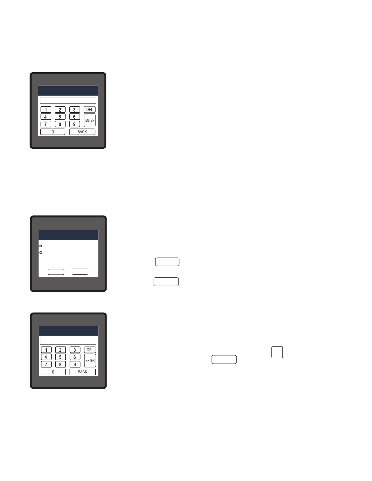
After touching “ SETUP” icon Password protection screen is
displayed. Screen consists of 0 to 9 digit input keypad for entering the
password very similar to any calculator in touchscreen mobile.“Enter
Password” is displayed on screen at start so that user can enter
password using displayed keypad.
Touching “ key” will display 1 in display area, similarly user can
enter remaining 3 digits.
For deleting any digit while entering password, user can touch “ key”.
After entering the complete password user needs to conrm password by touching “ key’’.
DEL
ENTER
ENTER
1
If Entered password is correct then “Password Accepted” is displayed on screen & user will on
screen & user will enter into setup menu.
Password conrmed.
If Entered password is wrong then “Password Rejected” is displayed on screen & user need to
re-enter the password After wrong password is entered, user needs to touch “ key ” for
trying another password.
Password Incorrect.
12
Page 15

Change Password Option is the second last option in list of “SETUP”
submenu, so can be accessed by a simple touch on “ Change
Password” button.
In this screen user rst needs to enter the current password.
3.1.1 Change Password
After input of correct password,“PASSWORD ACCEPTED”is
displayed & now user can enter the new 4 digit password.
After entering new password user needs to touch “ key” to
conrm.
After conrming “PASSWORD CHANGED” is displayed on screen,
which ensures successful changing of the password.
New Password conrmed.
3.2 Menu selection.
After entering in the SUBMENU 6 - SETUP, user will be asked to enter password & after
input of correct password list of following parameters will be displayed on screen :-
ENTER
13
Page 16

Touching on SYSTEM PARAMETER will open the system parameters list screen.Then these
screens from particular parameter may be scrolled through one at a time in incremental order
by touching the “ key” and in decremental order by touching “ key” on given touch
screen.
3.2.1 System Parameters Selection
After entering in the “SYSTEM PARAMETERS”, List of following parameters will be displayed :-
3.2.1.1 SYSTEM TYPE
3.2.1.2 PT PRIMARY
3.2.1.3 PT SECONDARY
3.2.1.4 CT PRIMARY
3.2.1.5 CT SECONDARY
3.2.1.7 DEMAND INTEGRATION TIME
3.2.1.8 AUTO SCROLL
3.2.1.9 LOW CURRENT NOISE CUTOFF
3.2.3 RESET PARAMETERS
3.2.4 OUTPUT OPTIONS
3.2.1.11 ENERGY RESOLUTION
3.2.1.12 ENERGY DIGIT RESET COUNT
3.2.5 DATALOGGING OPTIONS
3.2.6 POWER QUALITY SETTINGS
3.2.7 DATE & TIME SETTINGS
3.2.10 FACTORY RESET
3.2.8 BRIGHTNESS & CONTRAST
3.2.9 RGB COLOR CODE
3.2.1.6 SYSTEM FREQUENCY
3.2.1.10 NUMBER OF POLES
3.2.1.13 ENERGY UPDATE RATE
3.2.1.14 METER VERSION
3.2.1 SYSTEM PARAMETERS
3.2.2 COMMUNICATION PARAMETERS
14
Page 17
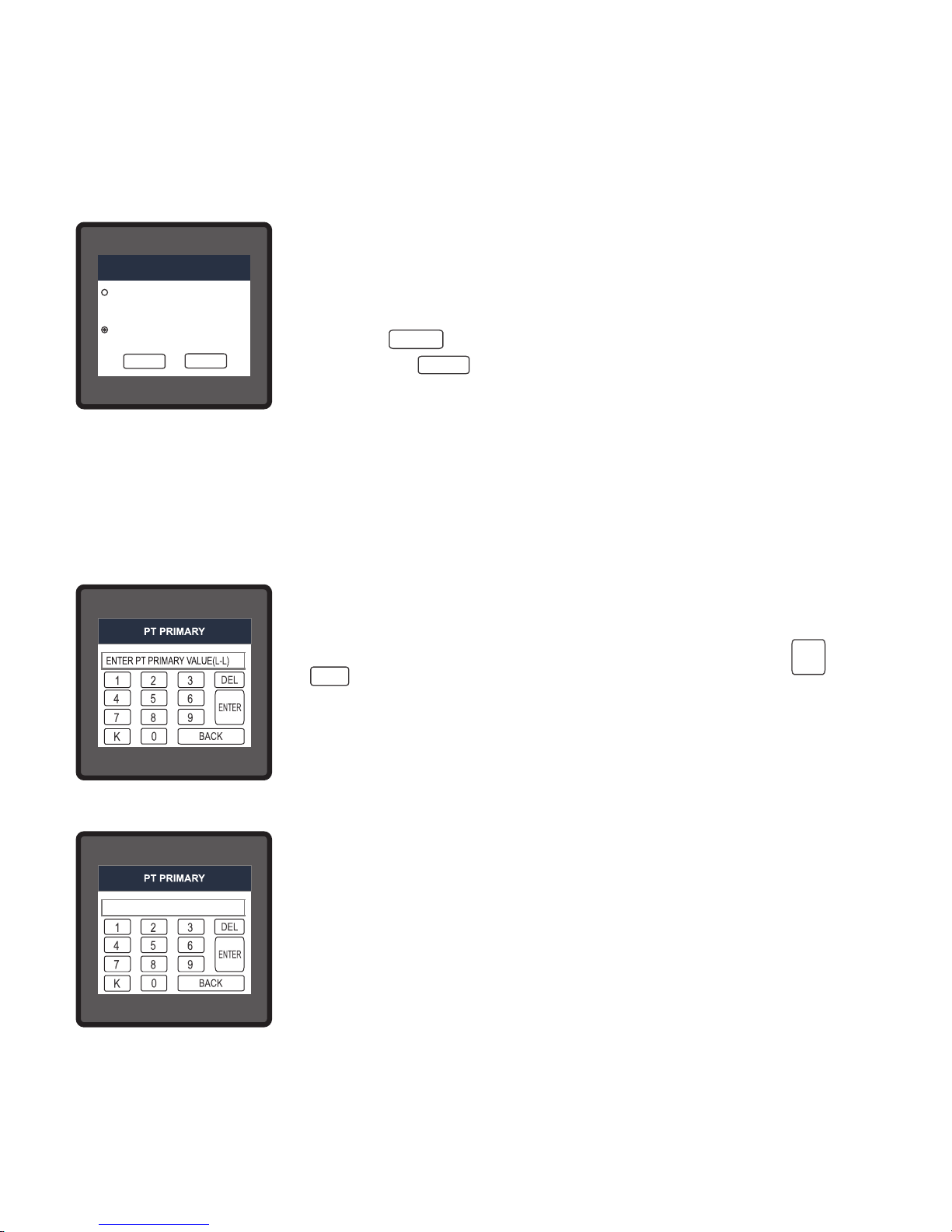
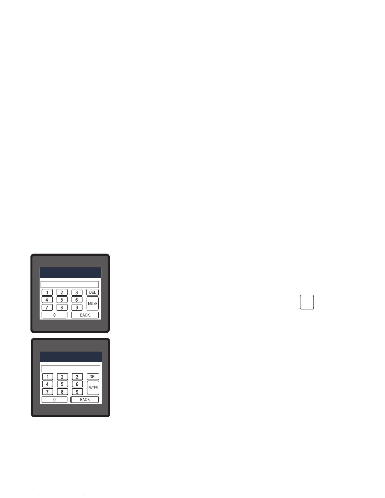
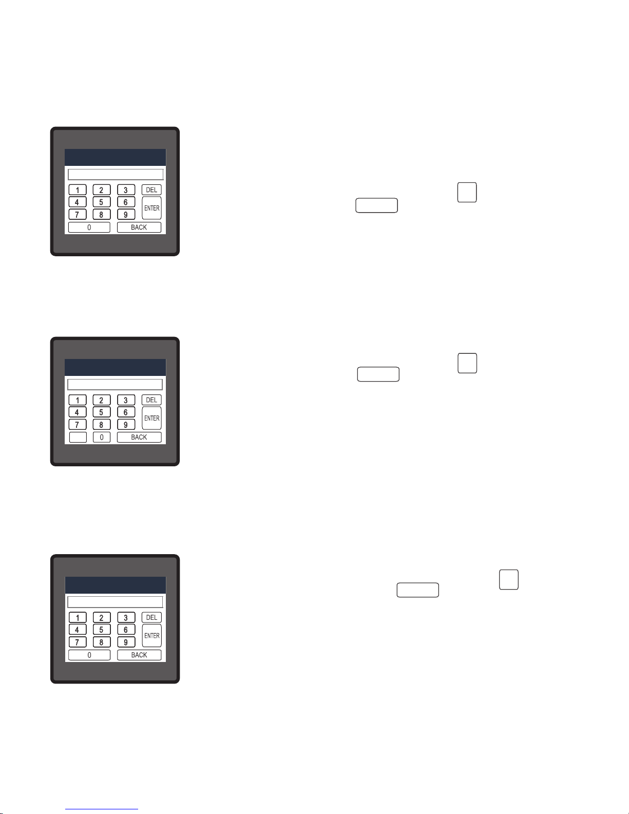
3.2.1.2 Potential Transformer Primary Value
The nominal full scale voltage will be displayed as Line to Line Voltages for 3 Phase 3 wire and
3 Phase 4 wire and 1 Phase 2 wire for Single Phase.
This screen can be accessed only from system parameters list menu.
Here again 0 to 9 digit input keypad is provided to set value of PT
Primary, & user can conrm this value with a simple touch “ key”.
“ key” is used to multiply value by 1000.
In case presently displayed Potential Transformer Primary value
together with the Current Transformer Primary value, previously set,
would result in a maximum power of greater than 666.6 MVA per
phase,”Invalid value” will be displayed. Then the valid range will be
displayed.
Valid range of PT primary setting value is
100V L-L to 692.8KV L-L.
If value outside the range is entered, It will display “INVALID VALUE”
followed by correct range of parameter.
Note : Changing PT Primary would erase the Sag and Swell data of
PQ events.
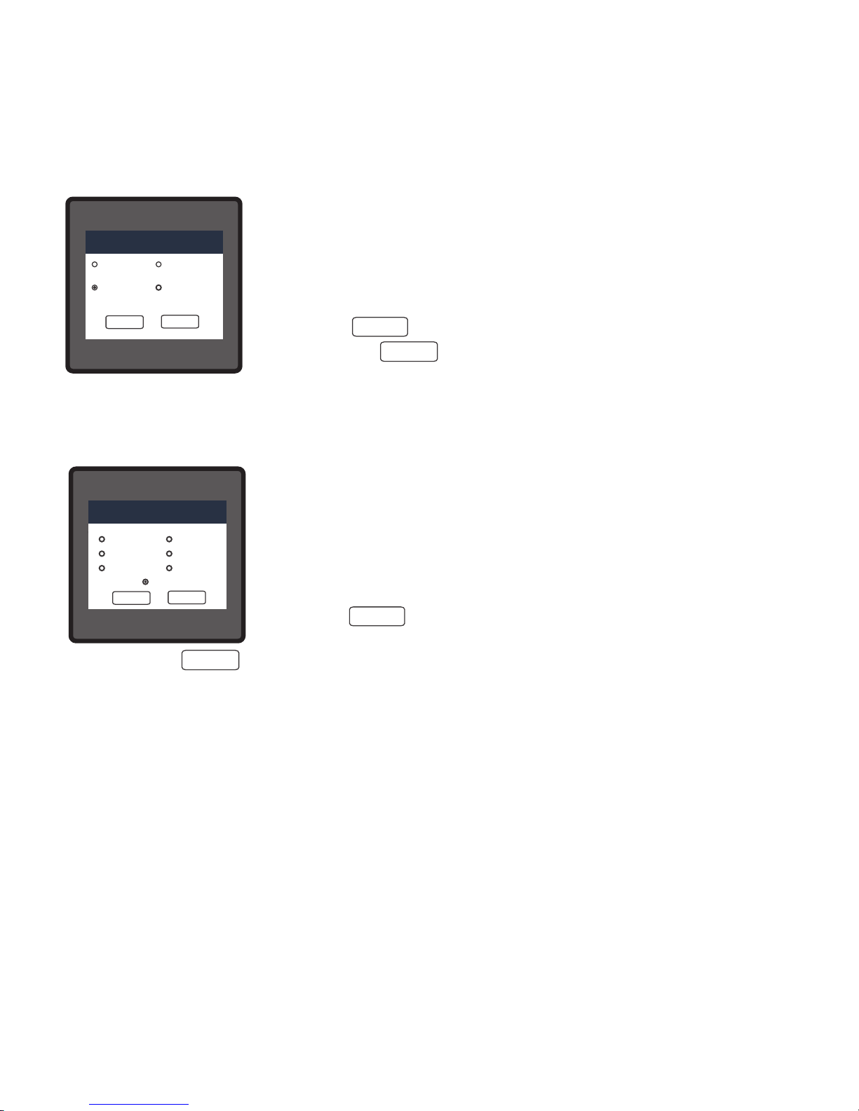
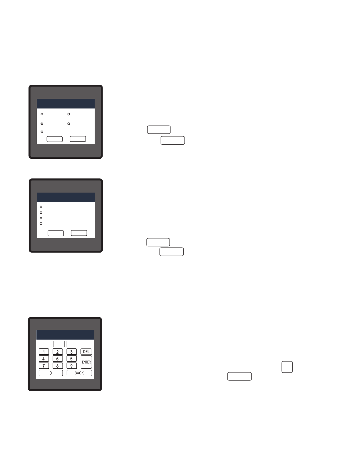
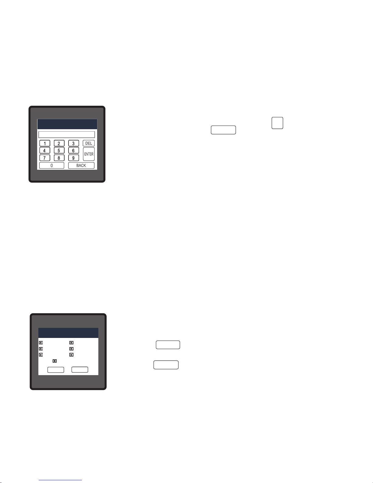
3.2.1.1 System Type
This screen is used to set the system type.
Two types: 3 phase 3 wire & 3 phase 4 wire system are displayed on
screen (for RM3440i). Touching radio button in front of particular type
will select that type.
Touch on “ key” will conrm the system type.
Touching the “ key” will keep the old selected setting and will
return to previous menu.
Note : If system type is changed, relay parameter selection & analog output selection will be set
to NONE and all the PQ event data (sag/ swell/ overcurrent) would be erased.
SYSTEM TYPE
3-PHASE 4 WIRE
FOR 3 PHASE STAR CONNECTED LOAD
3-PHASE 3 WIRE
FOR 3 PHASE DELTA CONNECTED LOAD
OK
BACK
OK
BACK
VALID RANGE IS : 100.0 TO 692800
K
ENTER
15
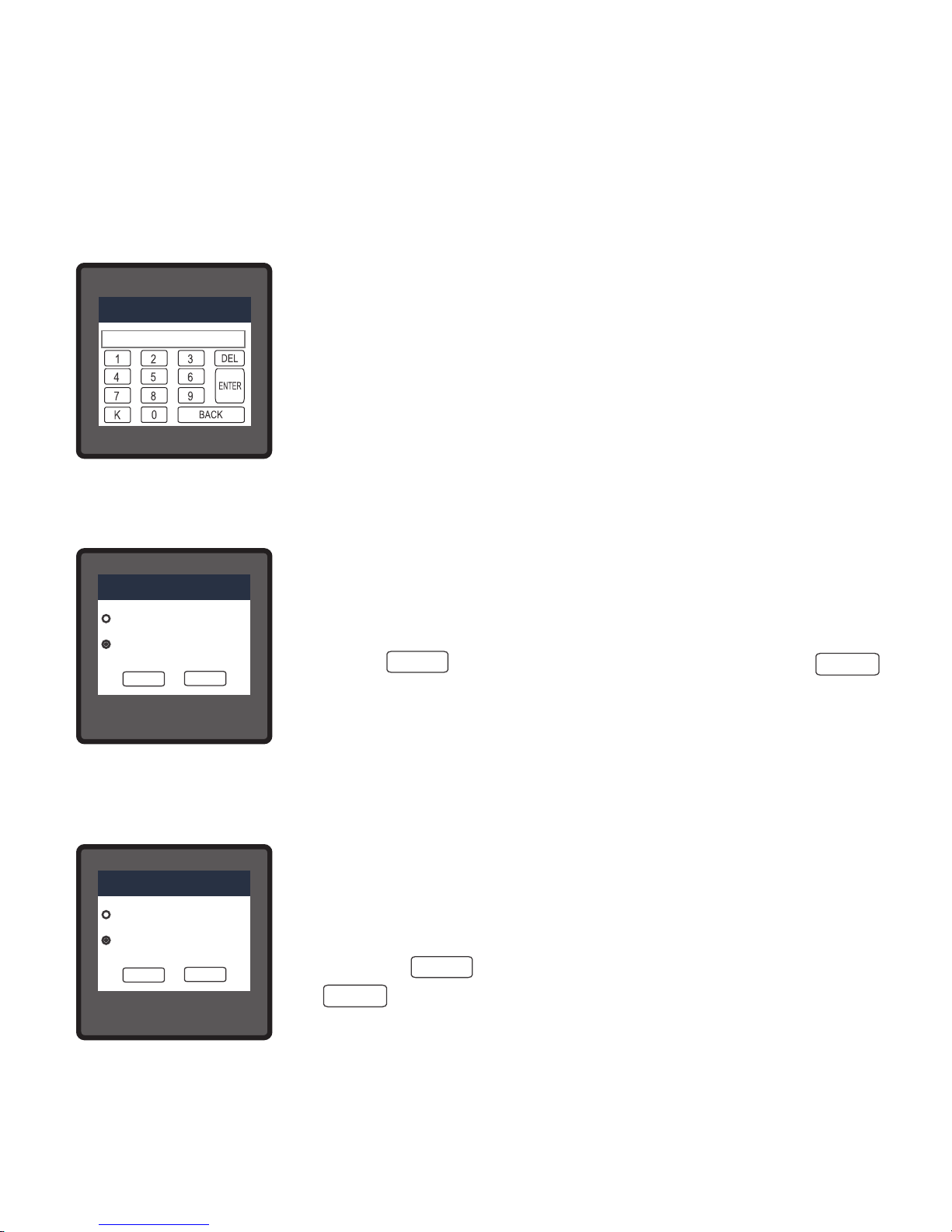
Page 18

INVALID VALUE
PT SECONDARY
The Valid range of instrument is from 100 to 600V.
If value outside the range is entered, It will display “INVALID VALUE”
followed by correct range of parameter.
Note : Changing PT Secondary would erase the Sag and Swell data
of PQ events.
3.2.1.3 Potential Transformer secondary Value
The value must be set to the nominal full scale secondary voltage which will be obtained from
the the Transformer when the potential transformer(PT)primary is supplied with the voltage
dened in 3.2.1.2 potential transformer primary voltage. The ratio of full scale primary to full
scale secondary is dened as the transformer ratio.
This screen can be accessed only from system parameters list menu. Here again 0 to 9 digit
input keypad is provided to set value of PT Secondary, & user can conrm this value with a
simple touch on “ key”.
ENTER
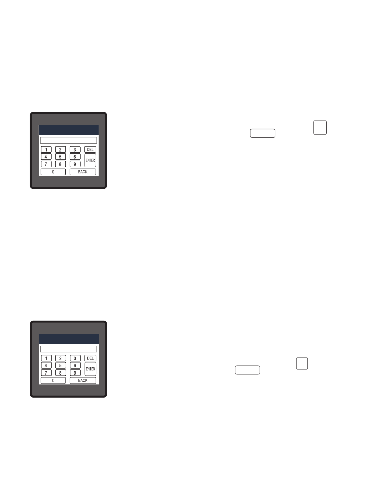
3.2.1.4 Current Transformer Primary Value
The nominal Full Scale Current that will be displayed as the Line currents. This screen enables
the user to display the Line currents inclusive of any transformer ratios, the values displayed
representthe Current in Amps.
This screen can be accessed only from system parameters list menu.
Here again 0 to 9 digit input keypad is provided to set value of CT
Primary & user can conrm this value with a simple touch on “ key”
and “ key” is used to multiply value by 1000. In case presently
displayed Current Transformer Primary Value together with the
Potential Transformer Primary Value results in a maximum power of
greater than 666.6 MVA, “invalid value” will be displayed. Example: If
primary value of PT is set as 692.8kV L-L (max value) then primary
value of Current is restricted to 1157A.
ENTER CT PRIMARY VALUE
ENTER
K
CT PRIMARY
16
Page 19
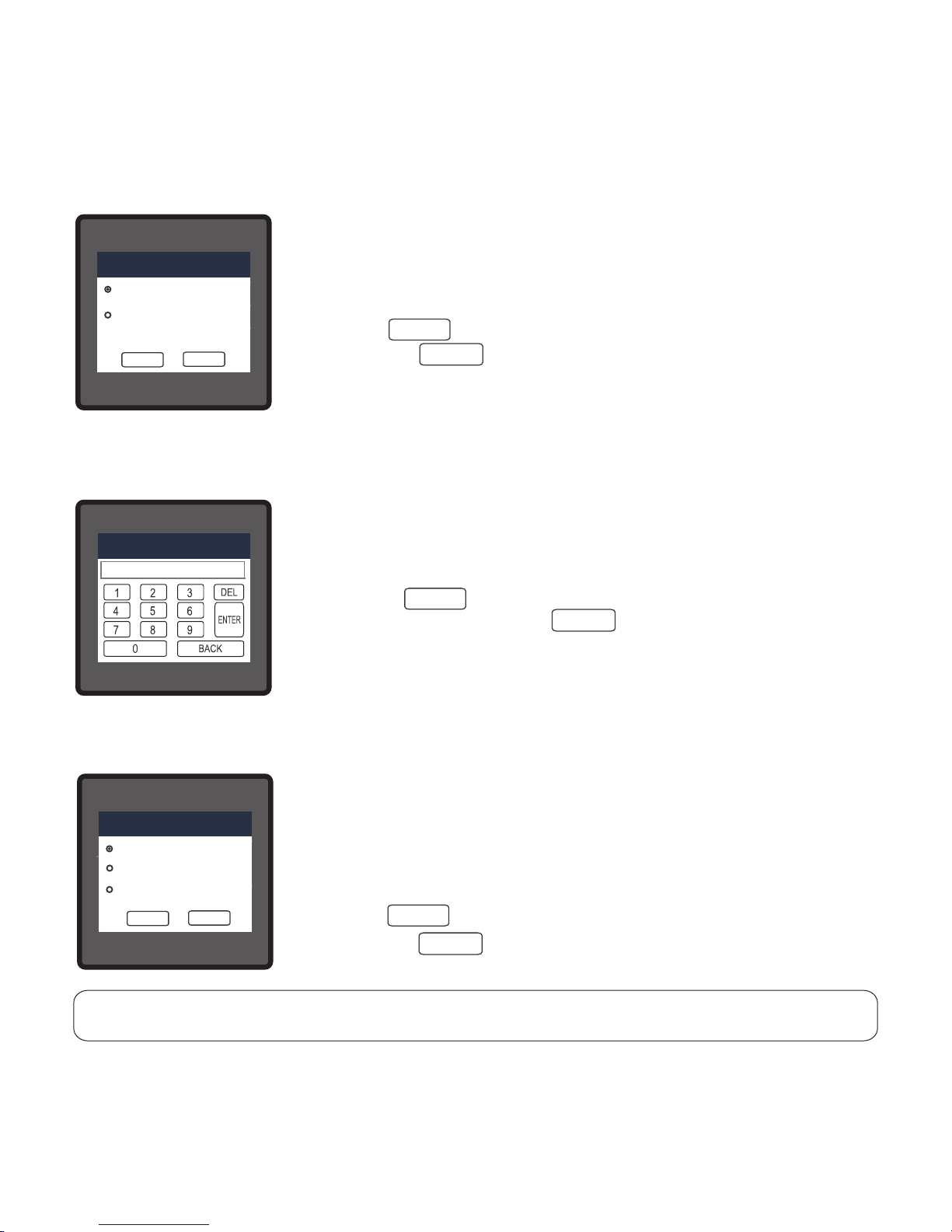
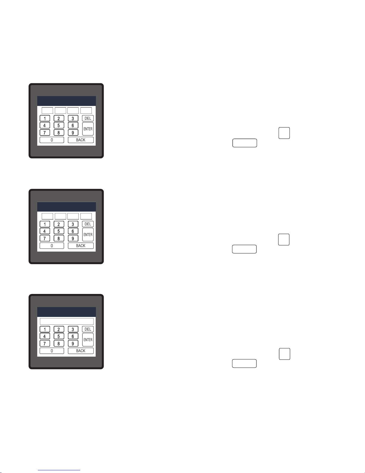
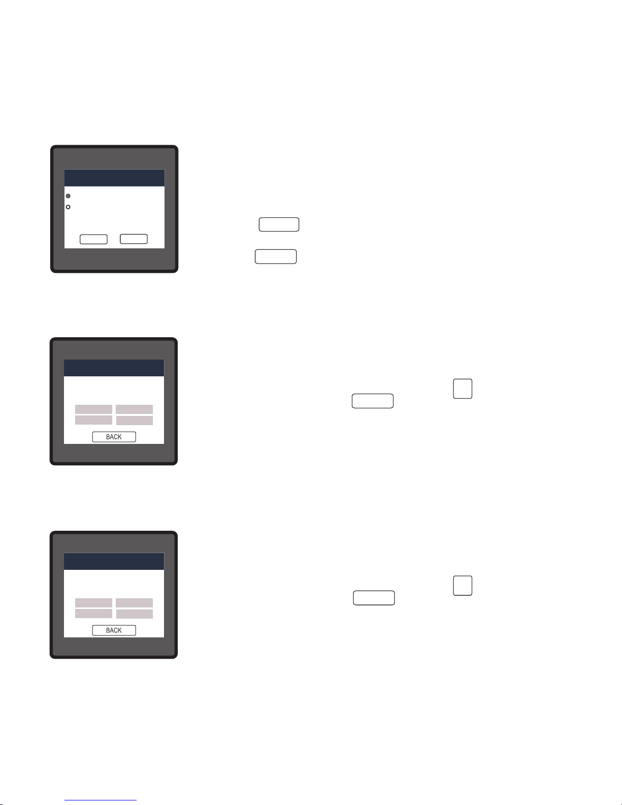
3.2.1.5 Current Transformer Secondary Value
This screen is used to set the secondary value for Current
Transformer. Two options: 1 AMPERE & 5 AMPERE are displayed on
screen. Touching radio button in front of particular option will select
that option.
Touch on “ key” will conrm the setting. Touching the “
key” will keep the old selected setting and will return to previous
menu.
Note : Changing CT Secondary would erase the Overcurrent data of
PQ events.
OK
OK
BACK
LINE-NEUTRAL VOLTAGE
VL2
VL2VL2
V
VVV
0.000
0.000
LINE-NEUTRAL VOLTAGE
VL2
VL2VL2
V
VVV
0.000
0.000
LINE-NEUTRAL VOLTAGE
VL2
VL2VL2
V
VVV
0.000
0.000
CT SECONDARY
5 AMPERE
1 AMPERE
LINE-NEUTRAL VOLTAGE
VL2
VL2VL2
V
VVV
0.000
0.000
LINE-NEUTRAL VOLTAGE
VL2
VL2VL2
V
VVV
0.000
0.000
CT SECONDARY
1 AMPERE
5 AMPERE
OK
BACK
The “Maximum Power” restriction of 666.6 MVA refers to 120% of nominal current and 120% of
nominal voltage, i.e, 462.96 MVA nominal power per phase.
Valid range of CT primary setting value is from 1 to 9999. If value
outside the range is entered, It will display “INVALID VALUE” followed
by correct range of parameter.
Note : Changing CT Primary would erase the Overcurrent data of PQ
events.
INVALID VALUE
3.2.1.6 System Frequency
OK
OK
BACK
LINE-NEUTRAL VOLTAGE
VL2
VL2VL2
V
VVV
0.000
0.000
LINE-NEUTRAL VOLTAGE
VL2
VL2VL2
V
VVV
0.000
0.000
LINE-NEUTRAL VOLTAGE
VL2
VL2VL2
V
VVV
0.000
0.000
CT SECONDARY
5 AMPERE
1 AMPERE
LINE-NEUTRAL VOLTAGE
VL2
VL2VL2
V
VVV
0.000
0.000
LINE-NEUTRAL VOLTAGE
VL2
VL2VL2
V
VVV
0.000
0.000
CT SECONDARY
1 AMPERE
5 AMPERE
OK
BACK
This screen is used to set the frequency of the input.
Two options : 50 & 60 Hz are displayed on screen.
Touching radio button in front of particular option will select that
option.
Touch on “ key” will confirm the setting. Touching the
“ key” will keep the old selected setting and will return to
previous screen.
CT PRIMARY
17
Page 20
LINE-NEUTRAL VOLTAGE
VL2
VL2
VL2
VVVV
0.000
0.000
LINE-NEUTRAL VOLTAGE
VL2
VL2
VL2
VVVV
0.000
0.000
LINE-NEUTRAL VOLTAGE
VL2
VL2
VL2
VVVV
0.000
0.000
CT SECONDARY
1 AMPERE
LINE-NEUTRAL VOLTAGE
VL2
VL2
VL2
VVVV
0.000
0.000
LINE-NEUTRAL VOLTAGE
VL2
VL2
VL2
VVVV
0.000
0.000
LINE-NEUTRAL VOLTAGE
VL2
VL2
VL2
VVVV
0.000
0.000
AUTO - SCROLL
ALL
VOLTAGE
POWER
NONE
SYSTEM
CURRENT
ENERGY
OK
BACK
3.2.1.7 Demand Integration Time
This screen is used to set the period over which current and power
readings are to be integrated.
Four options: 8, 15, 20, 30 Minutes are displayed on screen.
Touching radio button in front of particular option will select that
option.
Touch on “ key” will conrm the setting.
Touching the “ key” will keep the old selected setting and will
return to previous menu.
OK
OK
OK
OK
OK
BACK
BACK
LINE-NEUTRAL VOLTAGE
VL2
VL2VL2
0.000
0.000
LINE-NEUTRAL VOLTAGE
VL2
VL2VL2
0.000
0.000
LINE-NEUTRAL VOLTAGE
VL2
VL2VL2
0.000
0.000
CT SECONDARY
5 AMPERE
1 AMPERE
LINE-NEUTRAL VOLTAGE
VL2
VL2VL2
0.000
0.000
LINE-NEUTRAL VOLTAGE
VL2
VL2VL2
0.000
0.000
LINE-NEUTRAL VOLTAGE
VL2
VL2VL2
0.000
0.000
DEMAND INTEGRATION TIME
8 MINUTES
15 MINUTES
20 MINUTES
30 MINUTES
MAINMAINMAINMAINMAINMAIN
OK
BACK
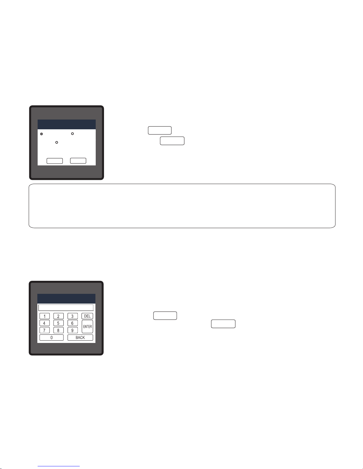
3.2.1.8 Auto Scrolling
This screen allows user to enable screen scrolling. Seven options :
ALL, SYSTEM, VOLTAGE, CURRENT, POWER, ENERGY & NONE
are displayed on screen. Touching radio button in front of particular
option will select that option. Selecting particular option means, only
screens which are under that submenu will be scrolled automatically.
Selecting NONE will disable Auto-Scroll.
Touch on “ key” will conrm the setting.
Touching the “ key” will keep the old selected setting and will return to previous menu.
While in Auto-scrolling mode, touch sense for entire screen will be disabled except for the top
right most corner where “A” symbol would be displayed stating that meter is in Auto-scroll mode.
Touching on “A” will show two options “ON” and “OFF”. Touching on “ON” will continue auto
scrolling & touching on “OFF” will stop auto-scrolling & return to normal mode.
18
Page 21
BACK
OK
OK
3.2.1.10 Number of Poles
This screen enables to set No. of poles of a Generator of which RPM is to be measured and to
which the instrument is connected to monitor its parameters.
INVALID VALUE
NUMBER OF POLES
The valid range of number of poles is from 2 to 40.
If an odd value or a value outside the range is entered, It will display
“INVALID VALUE” followed by the correct range of parameter.
Touch on “ key” will conrm the setting and will return to
previous menu. Touching the “ key” will keep the old selected
setting.
3.2.1.9 Low Current noise cutoff
This screen allows the user to set Low noise current cutoff in mA.
Two options, 0 MILLI-AMPERE & 30 MILLI-AMPERE are displayed on
screen. Touching radio button in front of particular option will select
that option.
Touch on “ key” will conrm the setting.
Touching the “ key” will keep the old selected setting and will
return to previous menu.
LINE-NEUTRAL VOLTAGE
VL2
VL2VL2
LINE-NEUTRAL VOLTAGE
VL2
VL2VL2
LINE-NEUTRAL VOLTAGE
VL2
VL2VL2
CT SECONDARY
5 AMPERE
1 AMPERE
LINE-NEUTRAL VOLTAGE
VL2
VL2VL2
LINE-NEUTRAL VOLTAGE
VL2
VL2VL2
LINE-NEUTRAL VOLTAGE
VL2
VL2VL2
LOW CURRENT NOISE CUTOFF
0 MILLI-AMPERE
30 MILLI-AMPERE
OK
BACK
BACK
OK
OK
BACK
OK
OK
depending as per the user’s requirement.
This setting is applicable for all types of energy.
Three options: WATT, KILO-WATT & MEGA-WATT are displayed on
screen. Touching radio button in front of particular option will select
that option.
Touch on “ key” will conrm the setting.
Touching the “ key” will keep the old selected setting and will
return to previous menu.
3.2.1.11 Energy Resolution
This screen enable user to set energy in terms of Wh / kWh / MWh on Rs485 Output
LINE-NEUTRAL VOLTAGE
VL2
VL2VL2
LINE-NEUTRAL VOLTAGE
VL2
VL2VL2
LINE-NEUTRAL VOLTAGE
VL2
VL2VL2
CT SECONDARY
5 AMPERE
1 AMPERE
LINE-NEUTRAL VOLTAGE
VL2
VL2VL2
LINE-NEUTRAL VOLTAGE
VL2
VL2VL2
LINE-NEUTRAL VOLTAGE
VL2
VL2VL2
ENERGY ON RS485
WATT (W)
KILO-WATT (KW)
MEGA-WATT (MW)
OK
BACK
Note :
Default value is set to ‘WATT’ i.e. Energy on Modbus will be in terms of
Wh/VArh/VAh respectively.
19
Page 22
3.2.1.12 Energy Digit Reset Count (Rollover Count)
This screen enables the user for setting maximum energy count after which energy will rollover
to zero. This rollover count values are 7, 8 and 9 Digits.
Touching radio button in front of particular option will select that
option.
Touch on “ key” will conrm the setting.
Touching the “ key” will keep the old selected setting and will
return to previous menu.
OK
OK
BACK
Note :-
1) If Energy Resolution is set to MW & energy digit reset count is set to 9, Energy
screen on display will show “-------” i.e energy overow when energy crosses the
8 digit count.
LINE-NEUTRAL VOLTAGE
VL2
VL2VL2
LINE-NEUTRAL VOLTAGE
VL2
VL2VL2
LINE-NEUTRAL VOLTAGE
VL2
VL2VL2
CT SECONDARY
1 AMPERE
LINE-NEUTRAL VOLTAGE
VL2
VL2VL2
LINE-NEUTRAL VOLTAGE
VL2
VL2VL2
LINE-NEUTRAL VOLTAGE
VL2
VL2VL2
ENERGY DIGIT RESET COUNT
7 DIGITS
9 DIGITS
8 DIGITS
OK
BACK
3.2.1.14 Meter Version
3.2.1.13 Energy Update Rate
This screen allows user to enter energy update rate in minutes. After entering particular value in
minutes, the energy will be updated on modbus location from 30145 to 30165 of 3X register and
40145 to 40165 of 4X register as per value that user has entered.
INVALID VALUE
ENERGY UPDATE RATE
BACK
OK
OK
The valid range of number of poles is from 1 to 60 minutes.
If a value outside the range is entered, It will display “INVALID
VALUE” followed by the correct range of parameter.
Touch on “ key” will conrm the setting and will return to
previous menu. Touching the “ key” will keep the old selected
setting.
If Energy Rate is set to 2 then energy will get stored after 2 minutes
on the modbus.
The meter version is available on the SYSTEM PARAMETERS screen as read only.
20
Page 23
3.2.2.1.1 RS485 Address Setting
This screen applies to the RS 485 output only. This screen allows the
user to set RS485 address parameter for the instrument. This screen
can be accessed only from Communication Parameters List menu.
Here again 0 to 9 digit input keypad is provided to set RS485 address
& user can conrm this value with a simple touch on “ key”.
The range of allowable address is 1 to 247.
If value outside the range is entered, it will display “INVALID VALUE”
followed by the correct range of parameter.
3.2.2.1.3 RS485 PARITY
3.2.2.1.1 RS485 ADDRESS
3.2.2.1.2 RS485 BAUD RATE
3.2.2 Communication Parameter Selection :
After entering in the “COMMUNICATION PARAMETERS” list of following parameters will be
displayed
ENTER RS485 ADDRESS
RS485 ADDRESS
RS485 ADDRESS
INVALID VALUE
3.2.2.1 MODBUS PARAMETERS
3.2.2.2.3 DEFAULT GATEWAY
3.2.2.2.1 IP ADDRESS
3.2.2.2.2 SUBNET MASK
3.2.2.2 ETHERNET PARAMETERS
3.2.2.2.4 SERVER PORT
3.2.2.1 Modbus Parameters Setting
ENTER
21
Page 24
3.2.2.1.2 RS 485 Baud Rate
This screen allows the user to set Baud Rate of RS 485 port.
Five options: 2400, 4800, 9600, 19200, 57600 Bauds are displayed
on screen. Touching radio button in front of particular option will
select that option.
Touch on “ key” will conrm the setting.
Touching the “ key” will keep the old selected setting and
will Return to previous menu.
BACK
OK
OK
LINE-NEUTRAL VOLTAGE
VL2
VL2
VL2
VL2
VL2
V
0.000
0.000
0.000
LINE-NEUTRAL VOLTAGE
VL2
VL2
VL2
VL2
VL2
V
0.000
0.000
0.000
LINE-NEUTRAL VOLTAGE
VL2
VL2
VL2
VL2
VL2
V
0.000
0.000
0.000
CT SECONDARY
5 AMPERE
5 AMPERE
1 AMPERE
LINE-NEUTRAL VOLTAGE
VL2
VL2
VL2
VL2
VL2
V
0.000
0.000
0.000
LINE-NEUTRAL VOLTAGE
VL2
VL2
VL2
VL2
VL2
V
0.000
0.000
0.000
LINE-NEUTRAL VOLTAGE
VL2
VL2
VL2
VL2
VL2
V
0.000
0.000
0.000
RS485 BAUD RATE
57600
38400
4800
9600
19200
OK
BACK
3.2.2.1.3 RS 485 Parity & Stop bit Selection
This screen allows the user to set Parity & number of stop bits.
Four options: ODD PARITY WITH ONE STOP BIT, NO PARITY WITH
ONE STOP BIT, NO PARITY WITH TWO STOP BITS, EVEN PARITY
WITH ONE STOP BIT are displayed on screen.
Touching radio buttion in front of particular option will select that
option.
Touch on “ key” will conrm the setting.
Touching the “ key” will keep the old selected setting and will
return to previous menu.
LINE-NEUTRAL VOLTAGE
VL2
VL2
VL2
VL2
LINE-NEUTRAL VOLTAGE
VL2
VL2
VL2
VL2
LINE-NEUTRAL VOLTAGE
VL2
VL2
VL2
VL2
5 AMPERE
1 AMPERE
LINE-NEUTRAL VOLTAGE
VL2
VL2
VL2
VL2
LINE-NEUTRAL VOLTAGE
VL2
VL2
VL2
VL2
LINE-NEUTRAL VOLTAGE
VL2
VL2
VL2
VL2
RS485 PARITY & STOP BITS
ODD PARITY WITH ONE STOP BIT
NO PARITY WITH ONE STOP BIT
NO PARITY WITH TWO STOP BIT
EVEN PARITY WITH ONE STOP BIT
OK
BACK
OK
OK
BACK
3.2.2.2.1 IP Address Setting
192
IP ADDRESS
ENTER
3.2.2.2 Ethernet Parameters Setting
These settings are available only when the addon Ehernet card is connected to the instrument.
168 001 037
The user can enter a valid IP Address value for each octet, i.e.
0 to 255.
Any value other than these would be indicated red and the previous
value will get restored.
The user can conrm the address by touching the “ key” and
cancel the change by touching the “ key”.
BACK
22
Page 25
3.2.2.2.2 Subnet Mask Setting
255
SUBNET MASK
ENTER
255 255 000
The user can enter a valid Subnet Mask value for each octet, i.e.
0 to 255.
Any value other than these would be indicated red and the previous
value will get restored.
The user can conrm the setting by touching the “ key” and
cancel the change by touching the “ key”.
BACK
3.2.2.2.3 Default Gateway Setting
192
DEFAULT GATEWAY
ENTER
168 001 001
The user can enter a valid Default Gateway value for each octet, i.e.
0 to 255.
Any value other than these would be indicated red and the previous
value will get restored.
The user can conrm the setting by touching the “ key” and
cancel the change by touching the “ key”.
BACK
3.2.2.2.4 Server Port Setting
INVALID VALUE
SERVER PORT
ENTER
This screen allows the user to enter the server port for the IP
settings.
The allowable range for server port value is 0 to 9999.
If value outside the range is entered, it will display “INVALID VALUE”
followed by the correct range of parameter.
The user can conrm the value by touching the “ key” and
cancel the change by touching the “ key”.
BACK
23
Page 26

3.2.3.1 Resetting Parameter
These screens allow the users to reset all the parameters eg:Energy, Min, Max, Demand, Run hour, On hour, No. of Interrupts, Sag
Data, Swell Data, Overcurrent Data.
Touching “ down” key scrolls list in upward direction. This screen is
displayed after repeatedly touching “ down” key.
Touching “ Up” key scrolls list in downward direction.
User needs to touch on the specic parameter to be reset.
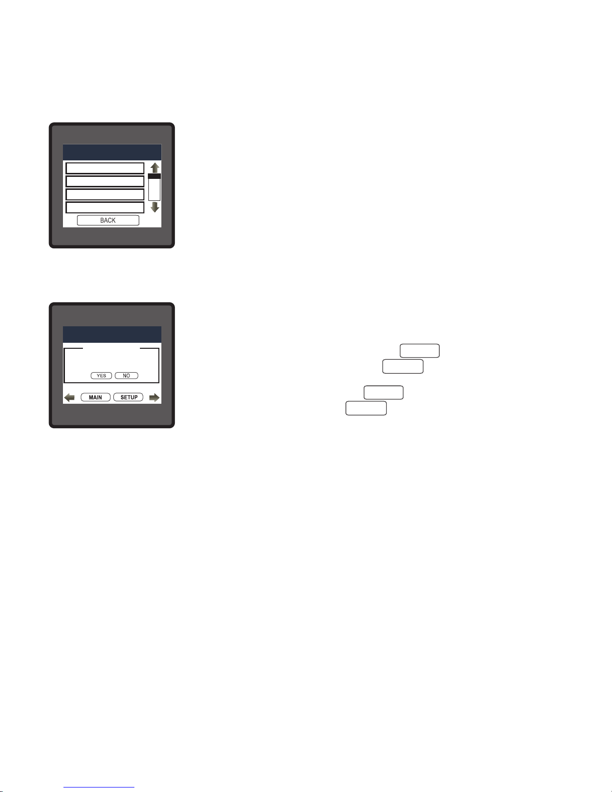
3.2.3 Reset Parameter Selection:-
Touching on any parameter will display the conrmation dialog, now a
touch on “ key” will conrm the resetting of that particular
Parameter.
Touching on “ key” will move back to Reset parameters menu.
For example resetting All Energies will display a conrmation dialog
as shown in the screen beside. User can reset other parameters in
similar manner
YES
NO
24
Page 27

3.2.4. Output Option selection menu
After entering in the “OUTPUT OPTIONS”, List of following parameters will be displayed :-
3.2.4.1 RELAY-1
3.2.4.2 RELAY-2
3.2.4.3 ANALOG-1
3.2.4.4 ANALOG-2
3.2.4.1 Relay1 output Selection menu
This screen applies to the Relay1 Output option Selection .
Four options : PULSE OUTPUT, LIMIT OUTPUT, TIMER & RTC
RELAY displayed on screen.
Touching any option will open screens of parameters related to that
option.
Touch on “ key” will take back to Output Options
screen.
3.2.4.1.1 Pulse output
After entering in the “PULSE OUTPUT”, List of following parameters will be displayed :-
3.2.4.1.1.1 ENERGY
3.2.4.1.1.2 PULSE DURATION
3.2.4.1.1.3 PULSE RATE
These settings are used to assign Relay1 in Pulse output mode.
LINE-NEUTRAL VOLTAGE
VL2
VL2VL2
V
0.000
0.000
LINE-NEUTRAL VOLTAGE
VL2
VL2VL2
V
0.000
0.000
LINE-NEUTRAL VOLTAGE
VL2
VL2VL2
V
0.000
0.000
CT SECONDARY
5 AMPERE
1 AMPERE
LINE-NEUTRAL VOLTAGE
VL2
VL2VL2
V
0.000
0.000
LINE-NEUTRAL VOLTAGE
VL2
VL2VL2
V
0.000
0.000
LINE-NEUTRAL VOLTAGE
VL2
VL2VL2
V
0.000
0.000
RELAY-1
PULSE OUTPUT
LIMIT OUTPUT
OUTPUT OPTIONS
OUTPUT OPTIONS
TIMER OUTPUT
RTC OUTPUT
25
Page 28

3.2.4.1.1.1 Assignment of Energy to pulse output (Relay 1) :
This screen allows the user to assign energy to pulse output (for Relay 1)
Following six options are displayed: Import Energy ( Active ) Export Energy ( Active )
Capacitive Energy (Reactive) Inductive Energy (Reactive)
Apparent Energy
Touching radio button in front of any particular option will select that
option.
Touch on “ key” will conrm the setting.
Touching the “ key” will keep the old selected setting and will
return to previous menu.
3.2.4.1.1.2 Pulse Duration Selection:
This screen applies only to the Pulsed output mode of both the relays.
This screen allows the user to set Relay energisation time in
milliseconds.
Three options: 60, 100, 200 ms are displayed on screen. Touching
radio button in front of particular option will select that option.
Touch on “ key” will conrm the setting.
Touching the “ key” will keep the old selected setting and will
return to previous menu.
3.2.4.1.1.3 Pulse Rate
This screen applies only to the Pulsed output mode of both the relays.
The screen allows user to set the energy pulse rate divisor.
Divisor values can be selected through 1,10, 100,1000.Touching radio
button in front of particular value will select that value.
Touch on “ key” will conrm the setting.
Touching the “ key” will keep the old selected setting and will
return to previous menu.
Pulse rate divisor is set to 1, when Energy on Rs485 is set to kWh or
MWh.
LINE-NEUTRAL VOLTAGE
VL2
VL2VL2
V
VVV
0.000
0.000
LINE-NEUTRAL VOLTAGE
VL2
VL2VL2
V
VVV
0.000
0.000
LINE-NEUTRAL VOLTAGE
VL2
VL2VL2
V
VVV
0.000
0.000
CT SECONDARY
5 AMPERE
1 AMPERE
LINE-NEUTRAL VOLTAGE
VL2
VL2VL2
V
VVV
0.000
0.000
LINE-NEUTRAL VOLTAGE
VL2
VL2VL2
V
VVV
0.000
0.000
LINE-NEUTRAL VOLTAGE
VL2
VL2VL2
V
VVV
0.000
0.000
RELAY-1 PULSE RATE DIVISOR
1
10
100
1000
OK
BACK
LINE-NEUTRAL VOLTAGE
VL2
VL2VL2
LINE-NEUTRAL VOLTAGE
VL2
VL2VL2
LINE-NEUTRAL VOLTAGE
VL2
VL2VL2
CT SECONDARY
5 AMPERE
1 AMPERE
LINE-NEUTRAL VOLTAGE
VL2
VL2VL2
LINE-NEUTRAL VOLTAGE
VL2
VL2VL2
LINE-NEUTRAL VOLTAGE
VL2
VL2VL2
RELAY-1 PULSE DURATION
60 MILLI-SECONDS
100 MILLI-SECONDS
200 MILLI-SECONDS
OK
BACK
OK
OK
OK
OK
OK
OK
BACK
BACK
BACK
LINE-NEUTRAL VOLTAGE
VL2
VL2
VL2
VL2
LINE-NEUTRAL VOLTAGE
VL2
VL2
VL2
VL2
LINE-NEUTRAL VOLTAGE
VL2
VL2
VL2
VL2
5 AMPERE
1 AMPERE
LINE-NEUTRAL VOLTAGE
VL2
VL2
VL2
VL2
LINE-NEUTRAL VOLTAGE
VL2
VL2
VL2
VL2
LINE-NEUTRAL VOLTAGE
VL2
VL2
VL2
VL2
RELAY-1 ENERGY ASSIGNMENT
APPARENT ENERGY
IMPORT ENERGY(ACTIVE)
EXPORT ENERGY(ACTIVE)
CAPACITIVE ENERGY(REACTIVE)
INDUCTIVE ENERGY(REACTIVE)
OK
BACK
26
Page 29

3.2.4.1.2 Limit output
This screen is for Limit output mode selection. It allows the user to set Limit output
corresponding measured value. After entering in Limit Output rst time(was disabled previously),
only “PARAMETER:” is displayed on screen. Now a simple touch on “PARAMETER:” will open
list of parameters, Refer TABLE 2 “Parameter for Analog & Limit output” for assignment. Now
after assignment of any parameter, list of following setting parameters will be displayed:-
3.2.4.1.2.1 LIMIT OUTPUT PARAMETER
3.2.4.1.2.2 ENERGY COUNT CONFIG
3.2.4.1.2.3 ENERGY TRIP POINT
3.2.4.1.2.4 ENERGY COUNT ON DELAY
3.2.4.1.2.5 PARAMETER CONFIG
3.2.4.1.2.6 TRIP POINT
3.2.4.1.2.1 Limit Parameter selection
This option allows the user to set Relay1 limit to corresponding measured parameter. A simple
touch on “PARAMETER” row will open screen having list of parameters. (Refer TABLE 2
“Parameters for Analog & Limit output”)
Touch on “ key” will conrm the setting.
Touching the “ key” will keep the old selected setting and will return to previous menu.
BACK
OK
OK
3.2.4.1.2.7 HYSTERESIS
3.2.4.1.2.8 ENERGIZING DELAY
3.2.4.1.2.9 DE-ENERGIZING DELAY
27
Page 30

Selecting Active Import/ Active Export/ Capacitive/ Inductive/ Apparent
Energy as Limit Output Parameter (see Section 3.2.4.1.2.1) allows the
user select one of the following configurations:
ENERGIZED RELAY (To Energize the Relay)
DE-ENERGIZED RELAY (To De-Energized the Relay)
Touch on “ key” will conrm the setting and take back to the
previous screen.
Touch on “ key” will take back to the previous screen.
3.2.4.1.2.2 Energy Count Conguration
3.2.4.1.2.3 Energy Trip Point
This screen is used to trip the relay using the energy count.
The relay trips after the lapse of “ON Delay” time (see Section
3.2.4.1.2.4) from the moment the energy count reaches the value of
Energy Trip Point set by the user in addition to its value at the
moment the Energy Trip Point is set.
Example: if the value set for Energy Trip Point is 888 and the
value of the corresponding parameter at the moment this value is set
is 1077, then the relay will trip after x sec of the moment the value of
the parameter becomes 1965 (= 1077 + 888), where x is the ON
Delay (see Section 3.2.4.1.2.4).
Caution:Once the relay has tripped, then to reactivate the Energy Tripping function,
the user has to either reset the energy or re-enter the energy count.
ENTER
BACK
Here 0 to 9 digit input keypad is provided to set the Energy Trip Point
& user can confirm this value with a simple touch on “ key”. and
cancel the change by touching the “ key”.
The valid range is 10 to 9999999.
If value outside this range is entered, it will display “INVALID VALUE”
followed by correct range of parameter.
ENTER TRIP POINT
RELAY-1 TRIP POINT
INVALID VALUE
RELAY-1 TRIP POINT
LINE-NEUTRAL VOLTAGE
VL2
VL2VL2
LINE-NEUTRAL VOLTAGE
VL2
VL2VL2
LINE-NEUTRAL VOLTAGE
VL2
VL2VL2
CT SECONDARY
5 AMPERE
1 AMPERE
LINE-NEUTRAL VOLTAGE
VL2
VL2VL2
LINE-NEUTRAL VOLTAGE
VL2
VL2VL2
LINE-NEUTRAL VOLTAGE
VL2
VL2VL2
RELAY-1 CONFIGURATION
ENERGIZED RELAY
DE-ENERGIZED RELAY
OK
BACK
OK
OK
BACK
This screen is used to set the Limit Configuration for Energy Count.
28
Page 31

3.2.4.1.2.4 Energy Count ON Delay
Here 0 to 9 digit input keypad is provided to set the Energy Count On
Delay & user can confirm this value with a simple touch on “ key”.
and cancel the change by touching the “ key”.
The valid range is 1 to 9999 seconds.
If value outside this range is entered, it will display “INVALID VALUE”
followed by correct range of parameter.
Selecting Limit Output Parameter (see Section 3.2.4.1.2.1) other than
Active Import/ Active Export/ Capacitive/ Inductive/ Apparent Energy
allows the user select one of the following configurations:
High Alarm & Energized Relay
High Alarm & De-Energized Relay
Low Alarm & Energized Relay
Low Alarm & De-Energized Relay
3.2.4.1.2.5 Parameter Conguration
ENTER
BACK
SET ON DELAY IN SEC
RELAY-1 ON DELAY
LINE-NEUTRAL VOLTAGE
VL2
VL2VL2
LINE-NEUTRAL VOLTAGE
VL2
VL2VL2
LINE-NEUTRAL VOLTAGE
VL2
VL2VL2
CT SECONDARY
5 AMPERE
1 AMPERE
LINE-NEUTRAL VOLTAGE
VL2
VL2VL2
LINE-NEUTRAL VOLTAGE
VL2
VL2VL2
LINE-NEUTRAL VOLTAGE
VL2
VL2VL2
RELAY-1 CONFIGURATION
OK
BACK
HIGH ALARM & DE-ENERGIZED RELAY
LOW ALARM & ENERGIZED RELAY
HIGH ALARM & ENERGIZED RELAY
LOW ALARM & DE-ENERGIZED RELAY
OK
OK
BACK
Touch on “ key” will conrm the setting and take back to the previous screen.
Touch on “ key” will take back to the previous screen.
(For details refer to section 9.2)
3.2.4.1.2.6 Trip Point
This screen applies to the Trip point selection for parameters other than Active Import/ Active
Export/ Capacitive/ Inductive/ Apparent Energy selected in Section 3.2.4.1.2.1. It allows the
user to set Trip point for instruments.
This screen allows the user to set ON Delay time in seconds for Relay Limit Assigned
Parameter. Refer Section 3.2.4.1.2.3 for details.
29
Page 32
The allowable range is 10% to 120% for High Alarm, 10% to 100%
for Low Alarm (refer TABLE 2).
Here 0 to 9 digit input keypad is provided to set the Trip Point & user
can confirm this value with a simple touch on “ key”. and cancel
the change by touching the “ key”.
If value outside the range is entered, it will display “INVALID VALUE”
followed by correct range of parameter.
ENTER TRIP POINT IN %
RELAY-1 TRIP POINT
ENTER
BACK
3.2.4.1.2.7 Hysteresis
Here 0 to 9 digit input keypad is provided to set the Hysteresis & user
can confirm this value with a simple touch on “ key”. and cancel
the change by touching the “ key”.
The allowable range is 0.5% to 50.0 % of Trip point.
If value outside the range is entered, it will display “INVALID VALUE”
followed by correct range of parameter.
(For details refer to section 9.2)
3.2.4.1.2.8 Energizing Delay
This screen allows the user to set Energizing Delay time in seconds for Relay Limit Assigned
Parameters.
SET HYSTERESIS IN %
RELAY-1 HYSTERESIS
.
ENTER
BACK
Here 0 to 9 digit input keypad is provided to set the Energizing Delay
& user can confirm this value with a simple touch on “ key”. and
cancel the change by touching the “ key”.
The allowable range is 0 to 9999 seconds.
If value outside the range is entered, it will display “INVALID VALUE”
followed by correct range of parameter.
(For details refer to section 9.2)
ENTER
BACK
SET ENERGIZING DELAY IN SEC
RELAY-1 ENERGIZING DELAY
This screen applies to the Hysteresis selection. This screen allows the user to set Hysteresis for
relay output.
30
Page 33
3.2.4.1.2.9 De-Energizing Delay
This screen allows the user to set De-Energizing Delay time in seconds for Relay Limit
Assigned Parameters.
Here 0 to 9 digit input keypad is provided to set the De-Energizing
delay & user can confirm this value with a simple touch on “ key”.
and cancel the change by touching the “ key”.
The allowable range is 0 to 9999 seconds.
If value outside the range is entered, it will display “INVALID VALUE”
followed by correct range of parameter.
(For details refer to section 9.2)
SET DE-ENERGIZING DELAY IN SEC
RELAY-1 DE-ENERGIZING DELAY
ENTER
BACK
3.2.4.1.3 Timer Output
After entering in the “TIMER OUTPUT”, List of following parameters will be displayed :-
3.2.4.1.3.1 NUMBER OF CYCLES
3.2.4.1.3.2 TIMER CONFIGURATION
3.2.4.1.3.3 ON DELAY
These settings are used to assign Relay1 in Timer output mode.
3.2.4.1.3.4 OFF DELAY
3.2.4.1.3.1 Number of Cycles
The value decides how many times the timer will repeat the switching
after it has been started in the timer based relay output option.
Here 0 to 9 digit input keypad is provided to set the No. of Cycles &
user can confirm this value with a simple touch on “ key”. and
cancel the change by touching the “ key”.
The value for this parameter can range from 0000 to 9999.
ENTER THE NO. OF CYCLES
RELAY-1 NO. OF CYCLES
ENTER
BACK
31
Page 34
If value outside this range is entered, it will display “INVALID VALUE”
followed by correct range of parameter.
If the value is set as 0000, the timer will keep repeating the cycles
until 9999 cycles are complete or the timer is stopped by the user.
Refer Section 9.3 for more details.
INVALID VALUE
RELAY-1 NO. OF CYCLES
Note: 1) To turn ON the relay in timer mode, visit “TIMER STATUS” submenu of SYSTEM
submenu in measurement screens.
2) The live status of No. of Cycles, ON & OFF delay is aslo available to the user in “TIMER 1”
and “TIMER 2” submenu of SYSTEM submenu in measurement screens for relay 1 and relay 2,
respectively.
3.2.4.1.3.2 Timer Configuration
The option decides the relay configuration for timer output. Two
options are available:
1. ENERGIZED RELAY: Energize on start
2. DE-ENERGIZED RELAY : De-energize on start.
Touch on “ key” will conrm the setting and take back to the
previous screen.
Touch on “ key” will take back to the previous screen.
3.2.4.1.3.3 On Delay
LINE-NEUTRAL VOLTAGE
VL2
VL2VL2
LINE-NEUTRAL VOLTAGE
VL2
VL2VL2
LINE-NEUTRAL VOLTAGE
VL2
VL2VL2
CT SECONDARY
5 AMPERE
1 AMPERE
LINE-NEUTRAL VOLTAGE
VL2
VL2VL2
LINE-NEUTRAL VOLTAGE
VL2
VL2VL2
LINE-NEUTRAL VOLTAGE
VL2
VL2VL2
RELAY-1 TIMER CONFIGURATION
ENERGIZED RELAY
DE-ENERGIZED RELAY
OK
BACK
OK
OK
BACK
The value decides the time in seconds taken by the relay in timer
configuration before tripping after it is started.
Here 0 to 9 digit input keypad is provided to set the On Delay & user
can confirm this value with a simple touch on “ key”. and cancel
the change by touching the “ key”.
The valid range is 1 to 9999 seconds.
If value outside this range is entered, it will display “INVALID VALUE”
followed by correct range of parameter.
ENTER
BACK
SET ON DELAY IN SEC
RELAY-1 TIMER ON DELAY
32
Page 35
3.2.4.1.3.4 Off Delay
Here 0 to 9 digit input keypad is provided to set the Off Delay & user
can confirm this value with a simple touch on “ key”. and cancel
the change by touching the “ key”.
The valid range is 1 to 9999 seconds.
If value outside this range is entered, it will display “INVALID VALUE”
followed by correct range of parameter.
ENTER
BACK
SET OFF DELAY IN SEC
RELAY-1 TIMER OFF DELAY
3.2.4.1.4.1 Weekdays Selection
This screen allows user to select the days of the week on which the
relay behaves as configured for RTC Relay settings.
Touch on “ key” will conrm the setting and take back to the
previous screen.
Touch on “ key” will take back to the previous screen.
3.2.4.1.4 RTC Output
After entering in the “RTC OUTPUT”, List of following parameters will be displayed :-
3.2.4.1.4.1 WEEKDAYS SELECTION
3.2.4.1.4.2 RELAY CONFIGURATION
3.2.4.1.4.3 ON TIME
These settings are used to assign Relay1 in RTC output mode.
3.2.4.1.4.4 OFF TIME
OK
OK
BACK
LINE-NEUTRAL VOLTAGELINE-NEUTRAL VOLTAGELINE-NEUTRAL VOLTAGE
CT SECONDARY
LINE-NEUTRAL VOLTAGELINE-NEUTRAL VOLTAGELINE-NEUTRAL VOLTAGE
RELAY-1 WEEKDAYS SELECTION
OK
BACK
Sunday Monday
Tuesday
Wednesday
Thursday Friday
Saturday
The value decides the time in seconds taken by the relay in timer configuration before coming
out of the trip state after it has tripped.
33
Page 36
3.2.4.1.4.2 Relay Conguration
The option decides the relay configuration for RTC output. Two
options are available:
1. ENERGIZED RELAY: Energize on start
2. DE-ENERGIZED RELAY : De-energize on start.
Touch on “ key” will conrm the setting and take back to the
previous screen.
Touch on “ key” will take back to the previous screen.
LINE-NEUTRAL VOLTAGE
VL2
VL2VL2
LINE-NEUTRAL VOLTAGE
VL2
VL2VL2
LINE-NEUTRAL VOLTAGE
VL2
VL2VL2
CT SECONDARY
5 AMPERE
1 AMPERE
LINE-NEUTRAL VOLTAGE
VL2
VL2VL2
LINE-NEUTRAL VOLTAGE
VL2
VL2VL2
LINE-NEUTRAL VOLTAGE
VL2
VL2VL2
RELAY-1 RTC CONFIGURATION
ENERGIZED RELAY
DE-ENERGIZED RELAY
OK
BACK
OK
OK
BACK
3.2.4.1.4.3 On Time
Here hour and minute settings can be done separately by touching
the corresponding value which will open the keypad.
The 0 to 9 digit input keypad is provided to set the On Time & user
can confirm this value with a simple touch on “ key”. and cancel
the change by touching the “ key”.
The valid range for hour is 0 to 23 and that for minute is 0 to 59.
If value outside this range is entered, it will display “INVALID VALUE”
followed by correct range of parameter.
ENTER
BACK
RELAY-1 ON TIME
3.2.4.1.4.4 Off Time
MINUTE
00
06
HOUR
RELAY-1 OFF TIME
MINUTE
00
18
HOUR
On Time is the time on which the relay becomes active.
Off Time is the time on which the relay deactivates.
Here hour and minute settings can be done separately by touching
the corresponding value which will open the keypad.
The 0 to 9 digit input keypad is provided to set the Off Time & user
can confirm this value with a simple touch on “ key”. and cancel
the change by touching the “ key”.
The valid range for hour is 0 to 23 and that for minute is 0 to 59.
If value outside this range is entered, it will display “INVALID VALUE”
followed by correct range of parameter.
ENTER
BACK
34
Page 37

3.2.4.2 Relay 2 Output Selection
Conguration of Relay 2 for Pulse/ Limit/ Timer/ RTC Output is same as Relay 1. If you Select
the Pulse output option for Relay 1 same setting will be applicable for Relay 2.
3.2.4.3 Parameter setting for Analog Output 1 ( Optional )
This option allows the user to set analog output 1 to corresponding measured parameter. A
simple touch on “ANALOG-1”row will open screen having list of parameters.(Refer TABLE 2
“ Parameter for Analog & Limit output ”)
Touch on “ key” will conrm the setting.
Touching the “ key” will keep the old selected setting and will return to previous menu.
BACK
OK
OK
3.2.4.4 Parameter setting for Analog Output 2 ( Optional )
This option allows the user to set analog output 2 to corresponding measured parameter. A
simple touch on “ANALOG-2”row will open screen having list of parameters.(Refer TABLE 2
“ Parameter for Analog & Limit output ”)
Touch on “ key” will conrm the setting.
Touching the “ key” will keep the old selected setting and will return to previous menu.
BACK
OK
OK
35
Page 38

3.2.5 Datalog Option Selection
3.2.5.1 Event Based Datalog Setup
Touching the “EVENT BASED DATALOG” option of Section 3.2.5
will provide a confirmation dialog.
If logging is turned off, then touching “ ” will turn on the
Event Based Datalogging while touching “ ” will make no
change.
If it is turned on, then touching “ ” will turn off the Event
Based Datalogging while touching “ ” will make no change.
After entering in the “DATALOGGING OPTIONS”, List of following
options will be displayed :-
3.2.5.1 EVENT BASED DATALOG
3.2.5.2 TIME BASED DATALOG
3.2.5.3 LOAD PROFILE DATALOG
Any of these can be selected for logging of data.
LINE-NEUTRAL VOLTAGELINE-NEUTRAL VOLTAGELINE-NEUTRAL VOLTAGE
CT SECONDARY
LINE-NEUTRAL VOLTAGELINE-NEUTRAL VOLTAGELINE-NEUTRAL VOLTAGE
DATALOGGING OPTIONS
MAIN
SETUP
EVENT BASED DATALOG
TIME BASED DATALOG
LOAD PROFILE DATALOG
DATALOGGING OPTIONS
EVENT BASED DATALOG
ARE YOU SURE YOU WANT TO START
EVENT BASED DATALOGGING
NO
OK
YES
NO
OK
YES
3.2.5.2 Time Based Datalog Setup
Following Time based datalog parameters can be set by touching the “TIME BASED DATALOG”
option of Section 3.2.5:
3.2.5.2.1. STATUS SELECTION
3.2.5.2.2. TIME INTERVAL
3.2.5.2.3. PARAMETER SELECTION
36
Page 39
3.2.5.2.1 Time Based Datalog Status Selection
Touching the “STATUS” option of Section 3.2.5.2 will provide a
confirmation dialog.
If logging is turned off, then touching “ ” will turn on the Time
Based Datalogging while touching “ ” will make no change.
If it is turned on, then touching “ ” will turn off the Time Based
Datalogging while touching “ ” will make no change.
TIME BASED DATALOGGING
TIME BASED DATALOG
ARE YOU SURE YOU WANT TO START
TIME BASED DATALOGGING
NO
OK
YES
NO
OK
YES
Caution: The settings for time based logging (see Section 3.2.5.2.2 & Section 3.2.5.2.3) are not
editable if time based datalog selection is turned ON (see Section 3.2.5.2.1).
3.2.5.2.2 Time Interval Selection
The value decides the time interval between two successive time
datalog entries.
Here 0 to 9 digit input keypad is provided to set the Time Interval &
user can confirm this value with a simple touch on “ key”. and
cancel the change by touching the “ key”.
The valid range is 1 to 60 minutes.
If value outside this range is entered, it will display “INVALID VALUE”
followed by correct range of parameter.
ENTER
BACK
ENTER INTERVAL IN MIN
DATALOG TIME INTERVAL
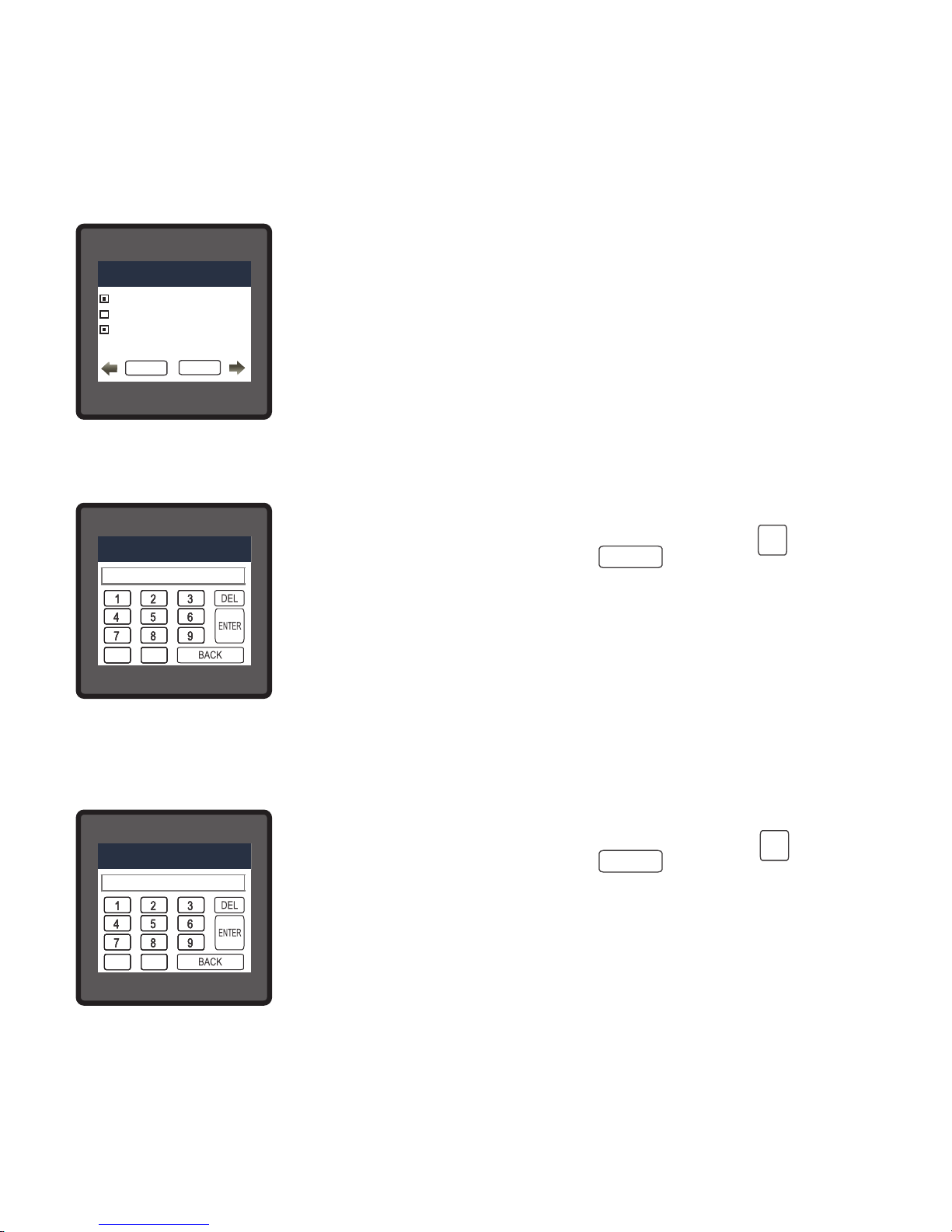
3.2.5.2.3 Parameter Selection
The parameter for time based datalogging can be selected out of the
available options by first touching the checkbox infront of it to enable
the selection and then touching the corresponding button to get the
available parameters.
Maximum 30 and minimum 1 parameter(s) can be chosen.
The list of available parameters is given in TABLE 3.
TIME DATALOG PARAMETERS
1. INPUT VOLTAGE VL1
2. INPUT VOLTAGE VL2
3. INPUT VOLTAGE VL1
4. INPUT VOLTAGE VL1
37
Page 40
TIME DATALOG PARAMETERS
INPUT VOLTAGE VL1
INPUT VOLTAGE VL2
INPUT VOLTAGE VL3
INPUT CURENT IL1
When the button (for which the checkbox is selected) is touched, the
list of available parameters (Table ) appear. The user can scroll for the
required parameter and select the same by touching it.
The number of parameters selected for datalogging appears on the
“TIME BASED DATALOGGING” screen (Section 3.2.5.2) for
PARAMETERS setting option.
Only these selected parameters will get logged.
3.2.5.3 Load Profile Datalog Setup
Touching the “LOAD PROFILE DATALOG” option of Section 3.2.5 will
provide a confirmation dialog.
If logging is turned off, then touching “ ” will turn on the Load
Profile Datalogging while touching “ ” will make no change.
If it is turned on, then touching “ ” will turn off the Load Profile
Datalogging while touching “ ” will make no change.
DATALOGGING OPTIONS
LOAD PROFILE DATALOG
ARE YOU SURE YOU WANT TO START
LOAD PROFILE DATALOGGING
NO
OK
YES
NO
OK
YES
38
Page 41
3.2.6 PQ Event Settings
3.2.6.1 Sag Threshold Setting
After entering in the “PQ EVENT SETTINGS”, List of following options
will be displayed :-
3.2.6.1 SAG THREHOLD
3.2.6.2 SWELL THRESHOLD
3.2.6.3 SAG & SWELL HYSTERESIS
3.2.6.4 OVERCURRENT THRESHOLD
3.2.6.5 OVERCURRENT HYSTERESIS
LINE-NEUTRAL VOLTAGELINE-NEUTRAL VOLTAGELINE-NEUTRAL VOLTAGE
CT SECONDARY
LINE-NEUTRAL VOLTAGELINE-NEUTRAL VOLTAGELINE-NEUTRAL VOLTAGE
DATALOGGING OPTIONS
MAIN
SETUP
EVENT BASED DATALOG
TIME BASED DATALOG
LOAD PROFILE DATALOG
Here 0 to 9 digit input keypad is provided to set the Sag Threshold &
user can confirm this value with a simple touch on “ key” and
cancel the change by touching the “ key”.
The valid range is 10 to 90 % of nominal voltage.
If value outside this range is entered, it will display “INVALID VALUE”
followed by correct range of parameter.
ENTER
BACK
ENTER SAG THRESHOLD IN %
SAG THRESHOLD
0
.
3.2.6.2 Swell Threshold Setting
Here 0 to 9 digit input keypad is provided to set the Swell Threshold &
user can confirm this value with a simple touch on “ key” and
cancel the change by touching the “ key”.
The valid range is 110 to 150 % of nominal voltage.
If value outside this range is entered, it will display “INVALID VALUE”
followed by correct range of parameter.
ENTER
BACK
ENTER SWELL THRESHOLD IN %
SWELL THRESHOLD
0
.
The value decides the threshold for swell detection.(Refer section 8 for details)
The value decides the threshold for sag detection.(Refer section 8 for details)
Note : Changing Swell Threshold would erase the Swell data of PQ events.
Note : Changing Sag Threshold would erase the Sag data of PQ events.
39
Page 42

3.2.6.3 Sag & Swell Hysteresis Setting
Here 0 to 9 digit input keypad is provided to set the Sag & Swell
Hysteresis & user can confirm this value with a simple touch on
“ key” and cancel the change by touching the “ key”.
The valid range is 1 to 20 % of nominal value.
If value outside this range is entered, it will display “INVALID VALUE”
followed by correct range of parameter.
ENTER
BACK
ENTER SAG & SWELL HYST IN %
SAG & SWELL HYSTERESIS
0
.
3.2.6.4 Overcurrent Threshold Setting
Here 0 to 9 digit input keypad is provided to set the Overcurrent
Threshold & user can confirm this value with a simple touch on
“ key” and cancel the change by touching the “ key”.
The valid range is 110 to 150 % of nominal current.
If value outside this range is entered, it will display “INVALID VALUE”
followed by correct range of parameter.
ENTER
BACK
ENTER OVR CRNT THRESHOLD IN %
OVERCURRENT THRESHOLD
0
.
The value decides the common hysteresis for sag & swell detection. Hysteresis is the difference
in magnitude between the start and end threshold.(Refer section 8 for details)
The value decides the threshold for overcurrent detection.(Refer section 8 for details)
Note : Changing Sag & Swell Hysteresis would erase the Sag & Swell data of PQ events.
Note : Changing Overcurrent Threshold would erase the Overcurrent data of PQ events.
40
Page 43

3.2.7 Date & Time Settings
After entering in the “DATE AND TIME SETUP”, the user will be able
to change the DATE, MONTH, YEAR, HOUR & MINUTE individually
by touching the corresponding option.
The range for date is 10-10-2000 to 31-12-2099 and that for time is
00:00 to 23:59.
Touching an option gives 0 to 9 digit input keypad to set the
corresponding value & user can confirm this value with a simple touch
on “ key” and cancel the change by touching the “ key”.
If invalid value is entered, it will display “INVALID VALUE” followed by
correct range of the parameter.
ENTER
BACK
ENTER THE DATE
DATE AND TIME SETUP
0
DATE AND TIME SETUP
2000
DATE
YEAR
01
MONTH
01
HOUR
11
MINUTE
10
3.2.6.5 Overcurrent Hysteresis Setting
Here 0 to 9 digit input keypad is provided to set the Overcurrent
Hysteresis & user can confirm this value with a simple touch on
“ key” and cancel the change by touching the “ key”.
The valid range is 1 to 20 % of nominal current.
If value outside this range is entered, it will display “INVALID VALUE”
followed by correct range of parameter.
ENTER
BACK
ENTER OVR CRNT HYSTERESIS IN %
OVERCURRENT HYSTERESIS
0
.
The value decides the hysteresis for overcurrent detection.Hysteresis is the difference in
magnitude between the start and end threshold.(Refer section 8 for details)
Note : Changing Overcurrent Hysteresis would erase the Overcurrent data of PQ events.
41
Page 44

3.2.8 Brightness & Contrast
The brightness & contrast of the TFT LCD screen can be varied by
the user by sliding the sliders. Touching the “ key” will conrm
the current brightness contrast setting.
Touching the DEFAULT key will set brightness and contrast as per
factory settings. Touching the BACK key will move back to the setup
menu without making any changes.
3.2.9 RGB Color Code (only for 3 Phase 3 Wire / 4 Wire)
This screen allows user to set the values of Red, Green and Blue
components of colors used to display the parameters of all three
phases.
Different colors can be assigned to each phase using combination of
Red, Green and Blue component values. L1,L2,L3 will be set to the
assigned color.
To set these values, touch the corresponding rectangular section, 0 to
9 digit input keypad will appear. After entering the value using this
keypad,user can conrm this value with a simple touch on “ key”.
“ key” is used to go back to previous screen.
OK
OK
140
R B
G
L1
L2
L3
RGB COLOR CODE
0 0
255 204191
0 255 0
RGB COLOR CODE
VALID RANGE IS : 0 to 255
The allowable range for these values is 0 to 255. If a value outside this range is entered, it will
display “ VALID RANGE IS : 0 TO 255”.
NOTE : Colors similar to background are not recommended.
42
Page 45

COLOR
R
G
B
Light Blue
Maroon
Pink
Purple
Red
Silver
Violet
White
Yellow
255 255 0
255 255 255
143 0 255
191 191 191
255 0 0
161 33 240
255 191 204
176 48 97
173 217 230
COLOR
R
G
B
Dark Pink
Dark Purple
Dark Red
Dark Violet
Dark Yellow
Gold
Gray
Green
Indigo
74 0
0 255 0
128 128 128
212 176 56
156 135 13
148 0 212
140 0 0
48 26 51
232 84 128
130
Standard color combinations
COLOR
R
G
B
Brass
Blue
Brown
Black
Bronze
Copper
Dark Blue
Dark Brown
Dark Green
0 51
102 66 33
0 0 140
184 115 51
166 41 41
204 128 51
181 166 66
0 0 255
0
0
0
33
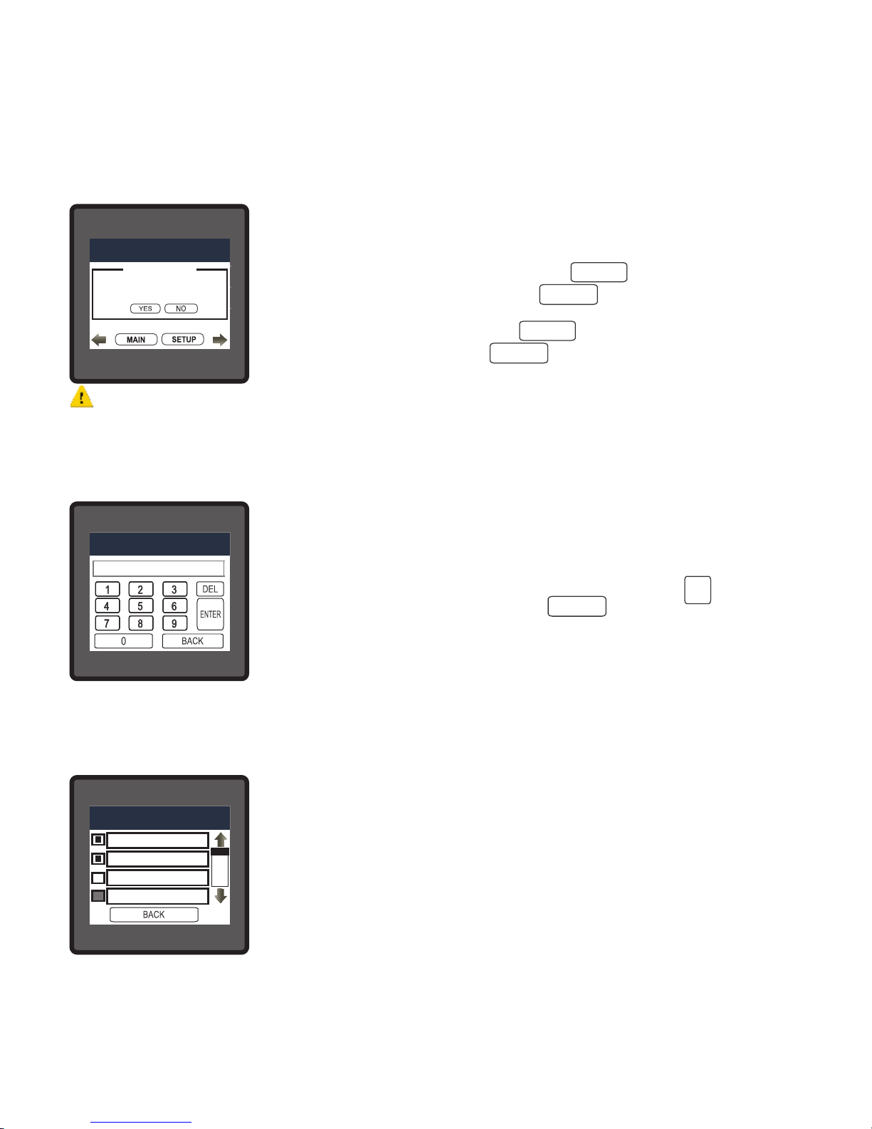
3.2.10 Factory Reset
Touching the “FACTORY RESET” option of Section 3.2 will provide a
confirmation dialog.
Touching “ ” allows the user to erase all data from the meter
and set all setup parameters to their default values while touching
“ ” will make no change.
SETUP
FACTORY RESET
THIS WILL RESET ALL DATA
DO YOU WANT TO CONTINUE?
NO
OK
YES
MAIN MENU
43
Page 46

LINE-NEUTRAL VOLTAGE
VOLTAGE
MAIN
VL2
VL2
VL2
VL2
V
VVVV
0.000
0.000
0.000
LINE-NEUTRAL VOLTAGE
VOLTAGE
MAIN
VL2
VL2
VL2
VL2
V
VVVV
0.000
0.000
0.000
LINE-NEUTRAL VOLTAGE
VOLTAGE
MAIN
VL2
VL2
VL2
VL2
V
VVVV
0.000
0.000
0.000
CT SECONDARY
OK
5 AMPERE
1 AMPERE
LINE-NEUTRAL VOLTAGE
VOLTAGE
MAIN
VL2
VL2
VL2
VL2
V
VVVV
0.000
0.000
0.000
LINE-NEUTRAL VOLTAGE
VOLTAGE
MAIN
VL2
VL2
VL2
VL2
V
VVVV
0.000
0.000
0.000
LINE-NEUTRAL VOLTAGE
VOLTAGE
MAIN
VL2
VL2
VL2
V
VVVV
0.000
0.000
0.000
IMPORTANT.
Performing touch
screen calibration.
Press & hold the center
of the filled circle
Touch screen to
continue.
4 Touch screen calibration
This instrument is able to perform calibration to ensure the proper operation of the units touch
screen functionalities. The calibration procedure will correct the problem of out of tolerance
touch screen malfunction. Note that errors corrected by this calibration procedure are specic
only to touch screen operation.
For starting touch screen calibration, touch the screen any where for 1
sec at system reset. After that touch screen calibration will start & the
message shown besides will be displayed. Touch the screen to
continue.
LINE-NEUTRAL VOLTAGE
VOLTAGE
MAIN
VL2
VL2
VL2
VL2
V
VVVV
0.000
0.000
0.000
LINE-NEUTRAL VOLTAGE
VOLTAGE
MAIN
VL2
VL2
VL2
VL2
V
VVVV
0.000
0.000
0.000
LINE-NEUTRAL VOLTAGE
VOLTAGE
MAIN
VL2
VL2
VL2
VL2
V
VVVV
0.000
0.000
0.000
CT SECONDARY
OK
5 AMPERE
1 AMPERE
LINE-NEUTRAL VOLTAGE
VOLTAGE
MAIN
VL2
VL2
VL2
VL2
V
VVVV
0.000
0.000
0.000
LINE-NEUTRAL VOLTAGE
VOLTAGE
MAIN
VL2
VL2
VL2
VL2
V
VVVV
0.000
0.000
0.000
LINE-NEUTRAL VOLTAGE
VOLTAGE
MAIN
VL2
VL2
VL2
V
VVVV
0.000
0.000
0.000
Hold
the filled
circle
LINE-NEUTRAL VOLTAGE
VOLTAGE
MAIN
VL2
VL2
VL2
VL2
V
VVVV
0.000
0.000
0.000
LINE-NEUTRAL VOLTAGE
VOLTAGE
MAIN
VL2
VL2
VL2
VL2
V
VVVV
0.000
0.000
0.000
LINE-NEUTRAL VOLTAGE
VOLTAGE
MAIN
VL2
VL2
VL2
VL2
V
VVVV
0.000
0.000
0.000
CT SECONDARY
OK
5 AMPERE
1 AMPERE
LINE-NEUTRAL VOLTAGE
VOLTAGE
MAIN
VL2
VL2
VL2
VL2
V
VVVV
0.000
0.000
0.000
LINE-NEUTRAL VOLTAGE
VOLTAGE
MAIN
VL2
VL2
VL2
VL2
V
VVVV
0.000
0.000
0.000
LINE-NEUTRAL VOLTAGE
VOLTAGE
MAIN
VL2
VL2
VL2
V
VVVV
0.000
0.000
0.000
Release
the filled
circle
LINE-NEUTRAL VOLTAGE
VOLTAGE
MAIN
VL2
VL2
VL2
VL2
V
VVVV
0.000
0.000
0.000
LINE-NEUTRAL VOLTAGE
VOLTAGE
MAIN
VL2
VL2
VL2
VL2
V
VVVV
0.000
0.000
0.000
LINE-NEUTRAL VOLTAGE
VOLTAGE
MAIN
VL2
VL2
VL2
VL2
V
VVVV
0.000
0.000
0.000
CT SECONDARY
OK
5 AMPERE
1 AMPERE
LINE-NEUTRAL VOLTAGE
VOLTAGE
MAIN
VL2
VL2
VL2
VL2
V
VVVV
0.000
0.000
0.000
LINE-NEUTRAL VOLTAGE
VOLTAGE
MAIN
VL2
VL2
VL2
VL2
V
VVVV
0.000
0.000
0.000
LINE-NEUTRAL VOLTAGE
VOLTAGE
MAIN
VL2
VL2
VL2
V
VVVV
0.000
0.000
0.000
Hold
the filled
circle
LINE-NEUTRAL VOLTAGE
VOLTAGE
MAIN
VL2
VL2
VL2
VL2
V
VVVV
0.000
0.000
0.000
LINE-NEUTRAL VOLTAGE
VOLTAGE
MAIN
VL2
VL2
VL2
VL2
V
VVVV
0.000
0.000
0.000
LINE-NEUTRAL VOLTAGE
VOLTAGE
MAIN
VL2
VL2
VL2
VL2
V
VVVV
0.000
0.000
0.000
CT SECONDARY
OK
5 AMPERE
1 AMPERE
LINE-NEUTRAL VOLTAGE
VOLTAGE
MAIN
VL2
VL2
VL2
VL2
V
VVVV
0.000
0.000
0.000
LINE-NEUTRAL VOLTAGE
VOLTAGE
MAIN
VL2
VL2
VL2
VL2
V
VVVV
0.000
0.000
0.000
LINE-NEUTRAL VOLTAGE
VOLTAGE
MAIN
VL2
VL2
VL2
V
VVVV
0.000
0.000
0.000
Press
on the filled
circle
Follow the instructions displayed. Press & hold the center of the lled red circle for at least 2
seconds. Release when message for release is being displayed. For accurate results try to
touch the center of the lled circle.
LINE-NEUTRAL VOLTAGE
VOLTAGE
MAIN
VL2
VL2
VL2
VL2
V
VVVV
0.000
0.000
0.000
LINE-NEUTRAL VOLTAGE
VOLTAGE
MAIN
VL2
VL2
VL2
VL2
V
VVVV
0.000
0.000
0.000
LINE-NEUTRAL VOLTAGE
VOLTAGE
MAIN
VL2
VL2
VL2
VL2
V
VVVV
0.000
0.000
0.000
CT SECONDARY
OK
5 AMPERE
1 AMPERE
LINE-NEUTRAL VOLTAGE
VOLTAGE
MAIN
VL2
VL2
VL2
VL2
V
VVVV
0.000
0.000
0.000
LINE-NEUTRAL VOLTAGE
VOLTAGE
MAIN
VL2
VL2
VL2
VL2
V
VVVV
0.000
0.000
0.000
LINE-NEUTRAL VOLTAGE
VOLTAGE
MAIN
VL2
VL2
VL2
V
VVVV
0.000
0.000
0.000
Press
on the filled
circle
Repeat the same
procedure for the
remaining 3
corner circles.
LINE-NEUTRAL VOLTAGE
VOLTAGE
MAIN
VL2
VL2
VL2
VL2
V
VVVV
0.000
0.000
0.000
LINE-NEUTRAL VOLTAGE
VOLTAGE
MAIN
VL2
VL2
VL2
VL2
V
VVVV
0.000
0.000
0.000
LINE-NEUTRAL VOLTAGE
VOLTAGE
MAIN
VL2
VL2
VL2
VL2
V
VVVV
0.000
0.000
0.000
CT SECONDARY
OK
5 AMPERE
1 AMPERE
LINE-NEUTRAL VOLTAGE
VOLTAGE
MAIN
VL2
VL2
VL2
VL2
V
VVVV
0.000
0.000
0.000
LINE-NEUTRAL VOLTAGE
VOLTAGE
MAIN
VL2
VL2
VL2
VL2
V
VVVV
0.000
0.000
0.000
LINE-NEUTRAL VOLTAGE
VOLTAGE
MAIN
VL2
VL2
VL2
V
VVVV
0.000
0.000
0.000
Hold screen for 1 sec
after system reset to
REPEAT the calibration
procedure.
Touch screen to
continue.
After successful
calibration, the
message shown
besides would be
displayed. Touch
the screen to
continue.
44
Page 47

LINE-NEUTRAL VOLTAGE
VOLTAGE
MAIN
VL2
VL2
VL2
VL2
V
VVVV
0.000
0.000
0.000
LINE-NEUTRAL VOLTAGE
VOLTAGE
MAIN
VL2
VL2
VL2
VL2
V
VVVV
0.000
0.000
0.000
LINE-NEUTRAL VOLTAGE
VOLTAGE
MAIN
VL2
VL2
VL2
VL2
V
VVVV
0.000
0.000
0.000
CT SECONDARY
OK
5 AMPERE
1 AMPERE
LINE-NEUTRAL VOLTAGE
VOLTAGE
MAIN
VL2
VL2
VL2
VL2
V
VVVV
0.000
0.000
0.000
LINE-NEUTRAL VOLTAGE
VOLTAGE
MAIN
VL2
VL2
VL2
VL2
V
VVVV
0.000
0.000
0.000
LINE-NEUTRAL VOLTAGE
VOLTAGE
MAIN
VL2
VL2
VL2
V
VVVV
0.000
0.000
0.000
Error in calibration
Touch screen to
re-calibrate.
If the touch screen was not calibrated properly, “Error in
calibration”message would be shown & the user will be asked to
recalibrate the touch screen. In such case the meter will retain the
previously stored touch - screen calibration values unless a
successful calibration is being performed.
Correct Phase sequence
This Screen indicates the phase sequence connected to meter is
correct. If phase sequence is wrong this screen is useful to get correct
phase sequence by interchanging connection & verifying it with
screen.
This Screen indicates that either of the phases or all three phases
(Voltages) are absent.
5. Phase Rotation Error screen(Only for 3P3W/4W)
Meter shows phase rotation error if the phase sequence R-Y-B (L1-L2L3) is not maintained This screen indicates that Phase sequence is
incorrect. User must check this screen in order to get correct readings
When meter is connected.
45
Page 48
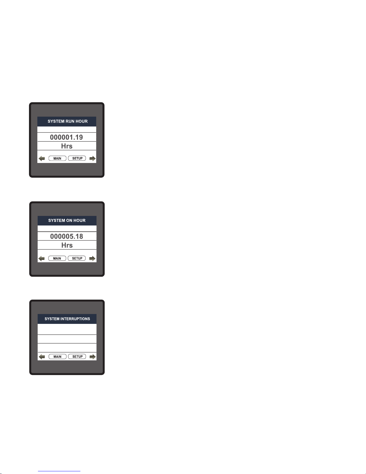
6.2. On Hour
This Screen shows the total no. of hours the Axillary Supply is ON.
Even if the Auxiliary supply is interrupted count of On hour will be
maintained in internal memory & displayed in the format “hours.
min”.
For example if Displayed count is 000005.18 hrs it indicates 15 hours
& 18 minutes.
After 999999.59 On hours display will restart from zero.
To reset On hour manually see section Resetting Parameter 3.2.3.1
6.3. Number of Interruption
This Screen Displays the total no. of times the Axillary Supply was
Interrupted. Even if the Auxiliary supply is interrupted count will be
maintained in internal memory.
To reset No of Interruption manually see section Resetting Parameter
3.2.3.1
00000012
6.1. Run Hour
This Screen shows the total no. of hours the load is connected.
Even if the Auxiliary supply is interrupted, the count of Run hour will
be maintained in internal memory & displayed in the format “hours.
min”. For example if Displayed count is 000001.19 hrs it indicates 1
hours & 19 minutes.
After 999999.59 run hours display will restart from zero.
To reset run hour manually see section Resetting Parameter 3.2.3.1
6. Run Hr, On Hr & No. of Interruptions
46
Page 49

Diagram 1 : ( 4 -20 mA )
0
0 (12 mA)
0
181 (4 mA)
0
180 (20 mA)
0
90 (16 mA)
0
270 (8 mA)
7. Analog Output ( optional ) :
This module provides two d.c. isolated outputs :
Two 4 - 20mA outputs , internally powered .
The output signals are present on pins A1(Analog Output 1) & A2 (Analog Output 2)
These outputs can be individually assigned to represent any one of the measured and displayed
Parameters.
All settings are user congurable via the user interface screen. See Analog o/p selection
(section 3.2.4.3 & section 3.2.4.4 ) for details .
* Note : Refer diagram 1
47
Page 50

TABLE 2 : Parameter for Analog & Limit Output
Parameter
No.
Parameter
3P
4W
3P
3W
1P
2W
Trip Point
Set Range
100%
Value
Vnom (L-N)
Vnom (L-N)
Vnom (L-N)
Inom
Inom
Inom
Nom
(3)
Nom
(3)
Nom
(3)
Nom
(3)
Nom
(3)
Nom
(3)
Nom
(3)
Nom
(3)
Nom
(3)
90°
90°
90°
360°
360°
360°
Vnom
(2)
Inom
Nom
(3)
Nom
(3)
Nom
(3)
90°
360°
66 Hz
(1)
Nom
(3)
10 - 120 %
10 - 120 %
10 - 120 %
10 - 120 %
10 - 120 %
10 - 120 %
10 - 120 %
10 - 120 %
10 - 120 %
10 - 120 %
10 - 120 %
10 - 120 %
10 - 120 %
10 - 120 %
10 - 120 %
10 - 90 %
10 - 90 %
10 - 90 %
10 - 90 %
10 - 90 %
10 - 90 %
10 - 120 %
10 - 120 %
10 - 120 %
10 - 120 %
10 - 120 %
10 - 90 %
10 - 90 %
10 - 90 %
10 - 9999999
None
Volts 1
Volts 2
Volts 3
IL1
IL2
IL3
W1
W2
W3
Va1
Va2
Va3
Var1
Var2
VAr3
PF1 #
PF2 #
PF3 #
PA1 #
PA2 #
PA3 #
Volts Ave
Current Ave
Watts sum
VA sum
VAr sum
PF Ave. #
PA Ave. #
Freq. #
Wh Import*
0
1
2
3
4
5
6
7
8
9
10
11
12
13
14
15
16
17
18
19
20
21
22
24
27
29
31
32
34
36
37
48
Page 51

TABLE 2 : Continued...
Parameter
No.
Parameter
3P
4W
3P
3W
1P
2W
Trip Point
Set Range
100%
Value
38
39
40
41
43
44
45
46
47
48
49
50
51
52
53
54
101
102
103
113
114
115
Wh Export*
VAr Capacitive*
VAr Inductive *
VA*
Watt Demand Imp.
Watt Max Demand Imp.
Watt Demand Exp.
Watt Demand Max Exp.
VAr Demand Cap.
VAr Max Demand Cap.
VAr Demand Ind.
VAr Demand Max Ind.
VA Demand
VA Max Demand
Current Demand
Current Max Demand
VL1-L2
VL2-L3
VL3-L1
I Neutral
Relay Manual OFF*
Relay Manual ON*
Nom
(3)
Nom
(3)
Nom
(3)
Nom
(3)
Nom
(3)
Nom
(3)
Nom
(3)
Nom
(3)
Nom
(3)
Nom
(3)
(3)
Nom
(3)
Nom
Nom
(3)
Nom
(3)
Inom
Inom
Vnom (L-L)
Vnom (L-L)
Vnom (L-L)
Inom
-
-
10 - 9999999
10 - 9999999
10 - 9999999
10 - 9999999
10 - 120 %
10 - 120 %
10 - 120 %
10 - 120 %
10 - 120 %
10 - 120 %
10 - 120 %
10 - 120 %
10 - 120 %
10 - 120 %
10 - 120 %
10 - 120 %
10 - 120 %
10 - 120 %
10 - 120 %
10 - 120 %
1
1
Note : Parameters 1,2,3 are L-N Voltage for 3P 4W & L-L Voltage for 3P 3W.
*Note : Parameters marked are not applicable for RM3440i and Analog output.
#Note : Refer #Note of Section 5.2 for details.
(1) For Frequency 0% corresponds to 45 Hz and 100% corresponds to 66 Hz.
(2) For 3P 4W and 1P2W the nominal value is VLN and that for 3P 3W is VLL.
(3) Nominal Value for power is calculated from Nominal Voltage and current values.
(4) Nominal Value is to be considered with set CT/ PT Primary values.
(5) For single phase L1 Phase values are to be considered as System values.
49
Page 52
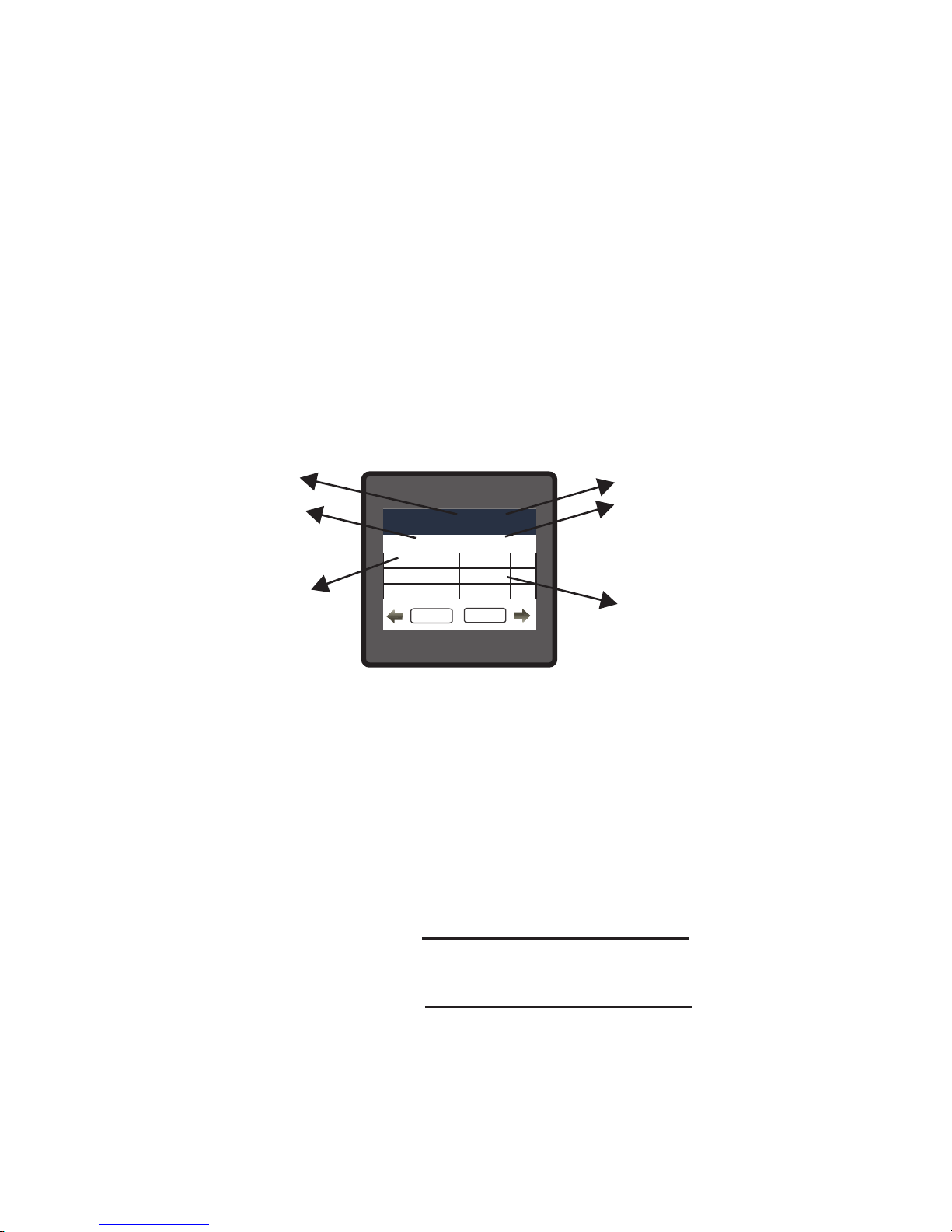
8. Power Quality Measurement:
The instrument measures the three power quality events, namely voltage sag, voltage swell and
overcurrent.
These events get stored in tabular form giving the corresponding date & time of event start and
its duration. The minimum event duration that can be recorded is 100mseconds.
Maximum of 30 such events get stored in the table one by one in the first in first out manner i.e.,
the 31st event replaces 1st event and so on.
Touching a particular event in the table gives the detailed information about the corresponding
event. Consider an example for SAG detection:
LINE-NEUTRAL VOLTAGELINE-NEUTRAL VOLTAGELINE-NEUTRAL VOLTAGE
CT SECONDARY
LINE-NEUTRAL VOLTAGELINE-NEUTRAL VOLTAGELINE-NEUTRAL VOLTAGE
EVENT 11 : SAG
MAIN
BACK
MIN AT L1
MIN AT L2
MIN AT L3
Event’s Start
Event’s End
188.9
No Event
187.2
V
V
V
Started at 12/08/2018,14:23:54 for 0.100 seconds
Date, Time of event
(DD/MM/YY, HH:MM:SS)
Duration of event
(Shows “POWERFAIL” when meter
turned off before end of the event)
Event Type (SAG/ SWELL/ OvI)
Minimum value during the event
“No Event” indicating normal value
during the event duration
Event number (1-30)
“Ëvent’s Start” indicates the phase which had the minimum value during the Event’s start and
“Ëvent’s End” indicates the phase which had the minimum value during the Event’s end.
In case of swell/ overcurrent event, MAX would appear in place of MIN and respective phase
readings would be taken considering the maximum values (instead of minimum values taken in
case of sag).
The Threshold and Hysteresis settings (Section 3.2.6) done in % by the user results in the
following values: (Consider Figure 9.1)
Threshold Value = (%Threshold) x Nominal Value
1 0 0
Hysteresis Value = (%Hysteresis) x Nominal Value
1 0 0
50
Page 53

Input (V)
time
0
Nominal value = 100V
Threshold value = 80V
Event Start Event End
Event Duration
Figure 9.1: Waveform of SAG detection for 1P2W system
Note:
(1) For the events to be detected, it is recommended to bring the system voltage and
current for all channels to their corresponding nominal values.
(2) The nominal voltage is the L-L PT Primary value in case of 3P3W system and L-N PT
Primary value in case of 3P4W and 1P2W system.
(3) The nominal current is taken to be CT Primary value.
(4) In case of polyphase systems, sag begins when the voltage of one or more channels
falls below the threshold and ends when the voltage on all measured channels is
above the threshold plus the hysteresis voltage (Figure 9.1). Similarly, the Swell/
Overcurrent event is shown in Figure 9.2.
Example for sag:
Nominal voltage = 100V
Threshold = 80% = 80V
Hysteresis = 2% = 2V
(Threshold+Hysteresis) value
= 80+2 = 82V
51
Page 54
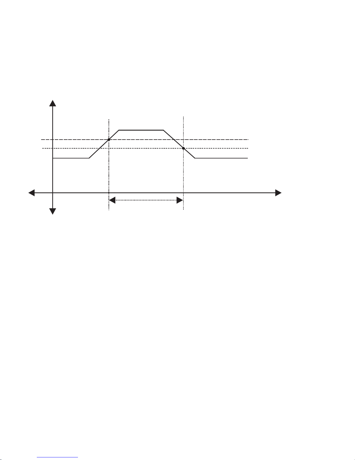
Input (V or I)
time
0
Nominal value
Threshold value
Event Start Event End
Event Duration
Figure 9.2: Waveform of SWELL/ OVERCURRENT detection for 1P2W system
(Threshold-Hysteresis) value
Example for swell/ overcurrent:
52
Page 55

Above options are also applicable for Apparent and Reactive Energy.
* System power = 3 x CT(Primary) x PT(Primary)L-N for 3 Phase 4 Wire
System power = Root3 x CT(Primary) x PT(Primary)L-L for 3 Phase 3 Wire
Pulse Duration 60 ms,100 ms or 200 ms
Divisor
1
10
100
1000
Pulse rate
Pulse
System Power*
1per Wh
1per 10Wh
1per 100Wh
1 per 1000Wh
1per kWh
1per 10kWh
1per 100kWh
1 per 1000kWh
1per Mwh
1per 10MWh
1per 100MWh
1per 1000MWh
Up to 3600W
Up to 3600W
Up to 3600W
Up to 3600W
Up to 3600kW
Up to 3600kW
Up to 3600kW
Up to 3600kW
Above 3600kW
Above 3600kW
Above 3600kW
Above 3600kW
TABLE 9.1.1 : Energy Pulse Rate Divisor
1.For Energy Output in Wh
Divisor
1
Pulse rate
Pulse
System Power*
1 per kWh
1 per 1000kWh
1 per 1000MWh
Up to 3600W
Up to 3600kW
Above 3600kW
2. For Energy Output in kWh
Divisor
1
Pulse rate
Pulse
System Power*
1 per MWh
1 per 1000MWh
1 per 1000GWh
Up to 3600W
Up to 3600kW
Above 3600kW
3. For Energy Output in MWh
9.1 Pulse Output :
Pulse output is the potential free, very fast acting relay contact which can be used to drive an
external mechanical counter for energy measurement.
This pulse output can be congured to any of the following parameter through instrument’s
setup parameter screen
1) Active Energy (Import) 2) Active Energy (Export)
3)Reactive Energy (Import) 4)Reactive Energy (Export)
5)Apparent Energy
This instrument is provided with either 1 or 2 relay for pulse output as well as for limit switch
9. Relay output (Optional) :
53
Page 56

Ampere Hour: Divisor 1(Default)
CT secondary = 1A Max pulse rate 3600 pulses per Ah **
CT secondary = 5A Max pulse rate 720 pulses per Ah **
Divisors 10
CT secondary = 1A Max pulse rate 3600 pulses per 10Ah **
CT secondary = 5A Max pulse rate 720 pulses per 10Ah **
Divisors 100
CT secondary = 1A Max pulse rate 3600 pulses per 100Ah **
CT secondary = 5A Max pulse rate 720 pulses per 100Ah **
Divisors 1000
CT secondary = 1A Max pulse rate 3600 pulses per 1000Ah **
CT secondary = 5A Max pulse rate 720 pulses per 1000Ah **
Pulse duration 60 ms, 100 ms or 200 ms
**No. of Pulses per Ampere hour = Maximum Pulses / CT Ratio Where, CT Ratio = (CT
primary/ CT Secondary)
9.2 Limit Switch :
Limit switch can be used to monitor the measured parameter (refer TABLE 2) in relation to a set
limit.
The limit switch can be congured in one of the four mode given below:-
1) Hi alarm & Relay Energized Relay.
2) Hi alarm & De-Energized Relay.
3) Lo alarm & Energized Relay.
4) Lo alarm & De-Energized Relay.
Limit switch has user selectable Trip point, Hysteresis, Energizing Delay & De-Energizing delay.
54
Page 57

Hi Alarm:
If Hi-Alarm Energized or Hi Alarm De-Energized option is selected then relay will get energized or Deenergized, if selected parameter is greater than or equal to trip point.
Lo Alarm:
If Lo-Alarm Energized or Lo Alarm De-Energized option is selected then relay will get energized or Deenergized, if selected parameter is less than or equal to trip point.
# Note: For Lo-Alarm configuration, set the values of trip point & hysteresis such that %
trip point + % hysteresis should be less than 100% Value.
Example for Phase angle:
If trip point is set 70% then maximum applicable hysteresis is 42.8%. i.e Trip point 70%
(252 ) + Hysteresis 42.8% (107.8 ) = 359.8 If total value is greater than the 100% i.e. ° ° °
360° then relay will not release.
0° (+1)
Relay De-energise
Relay Energise
0.4539(Trip point)
0.136(Hysterisis point)
180° (-1)
90° (0.00)
270° (0.00)
0.4539
0.136
Note: This function will work irrespective of +/sign. It depends only on value.
Trip point can be set in the range as specified in TABLE 3 of nominal value for Hi-Alarm & 10% to 100 % of
nominal value for Lo-Alarm.
Trip point:
Example for PF:
For Hi-Alarm Energized, if trip point is 70%
& hysterisis is 30%, then trip value =
0 . 7 x 9 0 ° = 6 3 ° . T r i p p i n g P F =
cos(63)=0.4539 & hysterisis = 0.3 x 0.4539
= 0.136.
Hence, the relay will energize above 0.4539 and deenergize below 0.3179.
Hysteresis can be set in the range of 0.5% to 50 % of set trip point. If Hi-alarm Energized or Hi-alarm Deenergized is selected then relay will get De-energized or Energized respectively, if set parameter value is
less than Hysteresis. Similarly if Lo-alarm Energized or Lo-alarm De-Energized.
Note : In case of lo alarm if trip point is set greater than 80% then the maximum hysteresis can be set such
that the total Trip point+ Hysteresis(% of trip point value) will not exceed 120% of range.
For example :If trip point is set at 90%, then maximum 33.3% hysteresis should be set such that, [90 + 29.99
(33.3% of 90)] = 120.
Hysteresis:
55
Page 58

Hysterisis point
Energizing Delay:
The energizing delay can be set in the range from 1 to 9999 seconds.
De-Energizing Delay:
The De-energizing delay can be set in the range from 1 to 9999 seconds.
56
Page 59
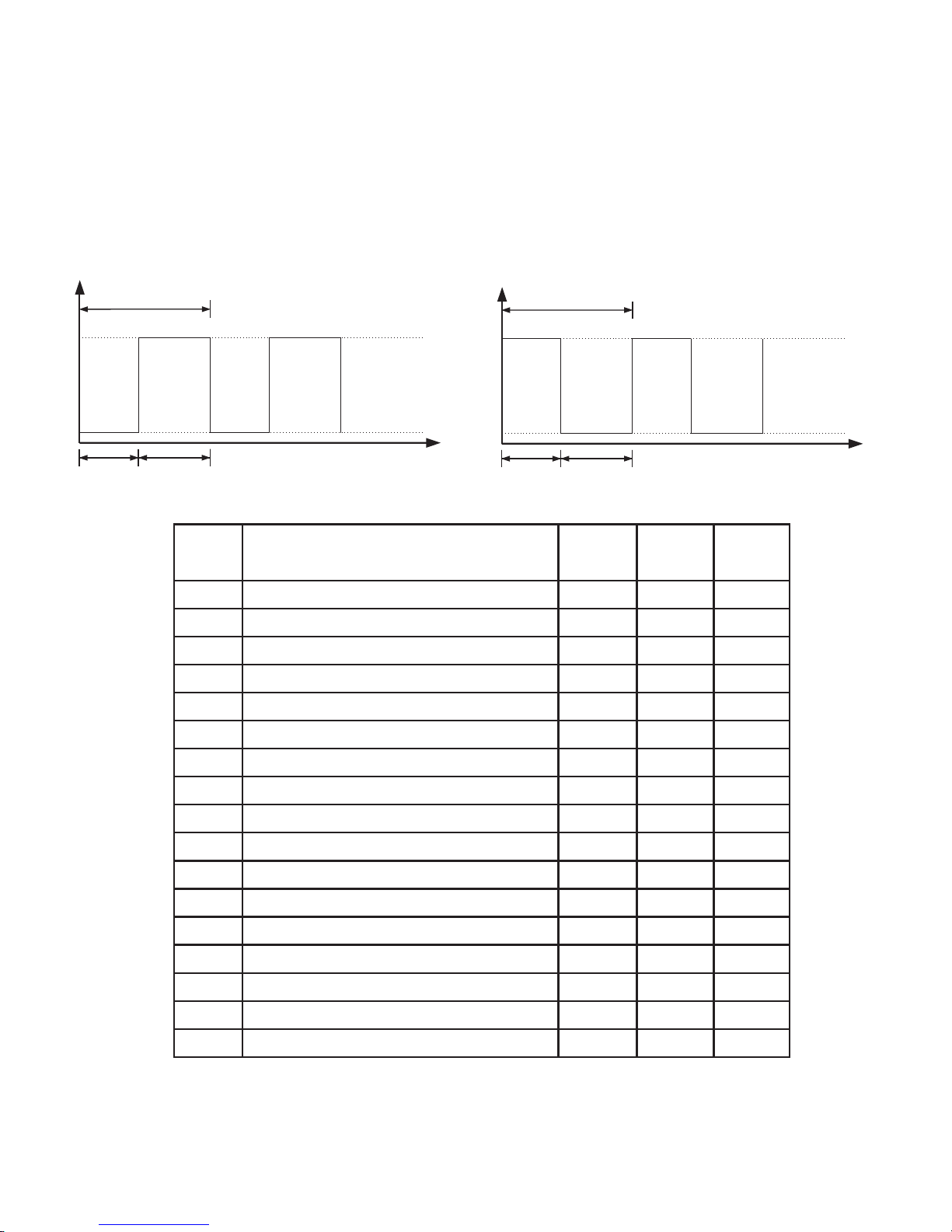
V1
V2
V3
I1
I2
I3
W1
W2
W3
VA1
VA2
VA3
VAR1
VAR2
VAR3
PF1
PF2
Para.
No.
Parameter
3P 4W
3P 3W 1P 2W
Parameter
0
1
2
3
4
5
6
7
8
9
10
11
12
13
14
15
16
TABLE 3 : Datalogging Parameters List
9.3 Timer Output
on delay off delay
repeat N times
Relay energised
Relay de-energised
time
De-energized configuration
on delay off delay
repeat N times
Relay energised
Relay de-energised
time
Energized configuration
Timer output can be used to operate the Relay in a cyclic manner. The user can define the ON period
and OFF period and also the number of times this cycle is to be repeated. The number of Cycles (N)
can be indefinite or 1 to 9999. The counting is shown on a measurement screen as explained before.
57
Page 60

PF3
Angle1
Angle2
Angle3
Volt Avg
Volt Sum
Current Avg
Current Sum
Watt Avg
Watt Sum
VA Avg
VA Sum
VAR Avg
VAR Sum
PF Avg
PF Sum
Phase Angle Avg
Phase Angle Sum
Freq
Wh import
Wh export
VARh Capacitive
VARh Inductive
VAh
kw imp demand
max kW imp demand
kW exp demand
max kW exp demand
kVAr Cap. demand
17
18
19
20
21
22
23
24
25
26
27
28
29
30
31
32
33
34
35
36
37
38
39
40
42
43
44
45
46
Para.
No.
Parameter
3P 4W
3P 3W 1P 2W
Parameter
TABLE 3: Continued...
58
Page 61

Para.
No.
Parameter
3P 4W
3P 3W 1P 2W
Parameter
47
48
49
50
51
52
53
54
56
58
60
62
66
67
68
70
71
100
101
102
103
104
105
106
107
108
109
110
112
max kVAr Cap. demand
kVAr Ind. demand
max kVAr Ind. demand
KVA demand
max KVA demand
current demand
max current demand
Wh Import Overflow Count
Wh Export Overflow Count
VARh Capacitive OF Count
VARh Inductive OF Count
Vah Overflow Count
system voltage max
system voltage min
RPM
system current max
system current min
V12
V23
V31
V THD-L1
V THD-L2
V THD-L3
I THD-L1
I THD-L2
I THD-L3
System V-THD
System I-THD
Neutral Current
TABLE 3: Continued...
59
Page 62

Para.
No.
Parameter
3P 4W
3P 3W 1P 2W
Parameter
113
114
115
166
Run hour
On Hour
No. of interrupts
Phase indicate
TABLE 3: Continued...
10. Phasor Diagram :
Capacitive
Inductive
Capacitive
Inductive
Connections Quadrant
Power ( P )
Sign of
Active
Power ( Q )
Sign of
Reactive
Factor ( PF )
Sign of
Power
Inductive /
Capacitive
Import
1
+ P
+ Q
+
L
Import
4
+ P
- Q
+
C
Export
2
- P
+ Q
-
C
Export
3
- P
- Q
-
L
Inductive means Current lags Voltage
When Multifunction Meter displays
Active power (P) with “ + ” (positive
sign), the connection is “Import ” .
When Multifunction Meter displays
Active power (P) with “ - ” (negative
sign), the connection is “Export ”.
Capacitive means Current leads Voltage
60
Page 63

11. Installation
Mounting is by four side clamps, slide the side clamps
through side slot till side clamp gets rmly locked in a
groove (Refer g.) Consideration should be given to the
space required behind the instrument to allow for
bends in the connection cables. As the front of the
enclosure conforms to IP54 it is protected from water
spray from all directions, additional protection to the
panel may be obtained by the use of an optional panel
gasket.
The terminals at the rear of the product should be
protected from liquids.
The instrument should be mounted in a reasonably
stable ambient temperature and where the operating
temperature is within the range -20 to 70 C.
SLIDE IN THIS DIRECTION
AND LOCK
PANEL
Meter
Caution
1. In the interest of safety and functionality this product must be installed by
a qualified engineer, abiding by any local regulations.
2. Voltages dangerous to human life are present at some of the terminal
connections of this unit. Ensure that all supplies are de-energised before
attempting any connection or disconnection.
3. These products do not have internal fuses therefore external fuses must
be used to ensure safety under fault conditions.
0
Vibration should be kept to a minimum and the product should not be mounted where it will be
subjected to excessive direct sunlight.
61
Page 64

11.1 EMC Installation Requirements
This product has been designed to meet the certication of the EU directives when installed to a
good code of practice for EMC in industrial environments, e.g.
1.
Screened output and low signal input leads or have provision for tting RF suppression
components, such as ferrite absorbers, line lters etc., in the event that RF elds cause
problems.
Note: It is good practice to install sensitive electronic instruments that are performing
critical functions, in EMC enclosures that protect against electrical interference which could
cause a disturbance in function.
2.
Avoid routing leads alongside cables and products that are, or could be, a source of
interference.
4. ESD precautions must be taken at all times when handling this product.
3.
To protect the product against permanent damage, surge transients must be limited to
2kV pk. It is good EMC practice to suppress differential surges to 2kV at the source. The
unit has been designed to automatically recover in the event of a high level of
transients. In extreme circumstances it may be necessary to temporarily disconnect the
auxiliary supply for a period of greater than 5 seconds to restore correct operation. The
Current inputs of these products are designed for connection in to systems via Current
Transformers only, where one side is grounded.
62
Page 65

11.2 Case Dimension and Panel Cut Out
3.78”
96mm
FRONT DISPLAY
AREA
3.78”
96mm
3.15”
80mm
3.62”
92mm
PANEL CUTOUT
3.62”
92mm
MAX PANEL THICKNESS 0.18”,5mm
11.3 Wiring
Input connections are made directly to screw-type terminals with indirect wire pressure.
Numbering is clearly marked in the plastic moulding. Choice of cable should meet local
regulations. Terminal for both Current and Voltage inputs will accept upto 3mm x 2 diameter
cables.
Note : It is recommended to use wire with lug for connection with meter.
2
11.4 Auxiliary Supply
The should ideally be powered from a dedicated supply, however it may be instrument powered
from the signal source, provided the source remains within the limits of the chosen auxiliary
voltage.
11.5 Fusing
It is recommended that all voltage lines are tted with 1 amp HRC fuses.
11.6 Earth/Ground Connections
For safety reasons, CT secondary connections should be grounded in accordance with local
regulations.
63
Page 66
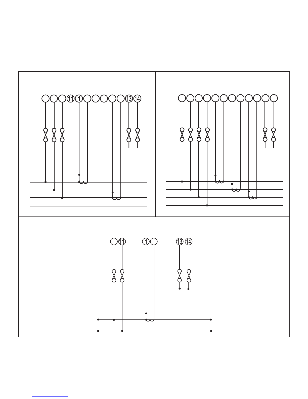
12. Connection Diagrams
3-PHASE 3-WIRE UNBALANCED LOAD
DIGITAL METERING SYSTEM
P1
S1
P1
S1
L N
AUX
SUPPLY
L1
L2
L3
N
L
O
A
D
2
5
8
3
4
6
7
9
3-PHASE 4-WIRE UNBALANCED LOAD
DIGITAL METERING SYSTEM
2
5
8
11 1
3
4
6
7
9
13
14
L N
AUX
SUPPLY
P1
S1
S1
P1
P1
S1
L1
L2
L3
N
L
O
A
D
SINGLE PHASE
DIGITAL METERING SYSTEM
P1
S1
L N
AUX
SUPPLY
L
N
L
O
A
D
2
3
64
Page 67

13. Specification
System
Display
Inputs
Nominal Input Voltage (AC RMS)
Max continuous input voltage
Nominal input voltage burden
System PT Primary Values
System PT Secondary Values
120% of Nominal Value
Nominal Input Current
1A/5A
Nominal input current burden
(Inbuilt CT)
max continuous input current
<0.3 VA approx. per phase
120% of Nominal value
Std. Values 1 to 9999A (1 or 5 Amp secondary)
1A / 5A, programmable on site
System CT secondary values
100VLL to 600VLL programmable on site.
(57.7VLN to 346.4VLN)
Overload Indication
“-OL-” >121% of Nominal value
(for voltage and current)
100VLL to 1200 kVLL, programmable on site
System CT primary values
2 x Rated Value
(1s application at 10s intervals) repeated 10 times
2 x nominal Value
(1s application at 5min intervals) repeated 5 times
Overload withstand
Current input
Voltage input
<0.3 VA approx. per Phase (at nominal 240V)
100VLL to 600VLL programmable on site.
(57.7VLN to 346.4VLN)
RM3440i (as per order ) : 3 Phase 3 Wire / 3 phase 4 Wire programmable at site
1 Phase 2 Wire
Approx. 1 seconds
Update
3.5" Graphical LCD, resolution 320x240 pixels
TFT LCD
Controls
Resistive Touch Screen
User Interface
RM3440iDL : 3 Phase 3 Wire / 3 phase 4 Wire /1 Phase 2 Wire
programmable at site
65
Page 68

Auxiliary Supply
External Higher Aux.
100V to 550V AC/DC
VA Burden With Addon card
Operating Measuring Ranges
Voltage
20 ... 120 % of nominal Value
Current
1....120% of nominal value
Frequency
45 to 65 Hz
Power Factor
0.5 Lag ... 1 ... 0.8 Lead
Starting Current
Total Harmonic Distortion
50% upto 15th harmonic
10% upto 31st harmonic
< 8 VA approx. (at nominal)
VA Burden With Ethernet card
< 9 VA approx. (at nominal)
Aux Frequency Range
45 to 65 Hz
External Higher Aux. Nominal Value
230V AC/DC 50/60 Hz for AC Aux
as per IEC 62053-22 (0.2S)
as per IEC 62053-22 (0.2S)
Accuracy
± 0.2 % of range
± 0.2 % of range
Frequency
0.15% of mid frequency
Active Energy
± 0.2 % of range
Active Power
± 0.4 % of range
Re- Active Power
± 0.2 % of range
Apparent Power
Re - Active Energy
Apparant Energy
± 0.2 % of range
Power Factor
± 1 % of Unity
Angle
± 1 % of range
Analog Output
± 1 % of Output end value
Total Harmonic Distortion
± 3 %
Neutral Current
± 4 % of range
Class 2 as per IEC 62053-23
External Lower Aux.
12V to 60V AC/DC
External Lower Aux. Nominal Value
24V AC/ 48V DC 50/60 Hz for AC Aux
Voltage
Current
66
Page 69

Nominal range of use of inuence quantities for measurands
50 .. 120 % of Rated Value
10 .. 120 % of Rated Value
Rated Value + 10 %
0
0 to 50 C
Voltage
Current
Input frequency
Temperature
Auxiliary supply voltage
Auxiliary supply frequency
Rated Value + 10 %
Rated Value + 10 %
Temperature Coefcient
0
0.025% / C for Voltage (50..120% of Rated Value)
(For Rated value range of use
0
0.05% / C for Current ( 10..120% of Rated Value )
0
0... 50 C )
Error change due to variation of an
inuence quantity
2 * Error allowed for the reference
condition applied in the test.
Reference conditions for Accuracy :
0 0
23 C + 2 C
50 or 60Hz ± 2%
Reference temperature
Input frequency
Sinusoidal (distortion factor 0.005)
Input waveform
Rated Value + 1 %
Auxiliary supply voltage
Auxiliary supply frequency
Rated Value + 1 %
Voltage Range
50... 100% of Nominal Value.
60... 100% of Nominal Value for THD.
Current Range
10... 100% of Nominal Value.
Power
cosØ / sinØ = 1
10... 100% of Nominal Current &
50... 100% of Nominal Voltage.
For Active / Reactive Power & Energy
20... 100% of Nominal Value for THD.
Power Factor / Phase Angle 40... 100% of Nominal Current &
50... 100% of Nominal Voltage.
67
Page 70

Standards
IEC 61326
10V/m min-Level 3 industrial low level
electromagnetic radiation environment
IEC 61000-4-3.
IEC 61010-1 , Year 2001
EMC Immunity
Safety
IEC 60529
IP for water & dust
Isolation
2.2 kV RMS 50 Hz for 1 minute
between all electrical circuits
Dielectric voltage withstand
test between circuits and
accessible surfaces
Environmental
0
-20 to +70 C
0
-25 to +75 C
0 .. 90 % RH
3 minute (minimum)
15g in 3 planes
10 .. 55 Hz, 0.15mm amplitude
IP 54 as per IEC 60529
Operating temperature
Storage temperature
Relative humidity
Warm up time
Shock
Vibration
Enclosure ( front only )
Enclosure
96mm x 96mm DIN Quadratic
Style
Polycarbonate Housing ,
Material
Self extinguish & non dripping as per UL 94 V-0
Screw-type terminals
Terminals
< 80 mm
Depth
0.620 kg Approx.
Weight
68
Page 71

Ethernet
Ethernet access on Modbus TCP/IP Protocol
Pulse output Option ( 1 or 2 Relay ) :
1NO + 1NC
Relay
240VDC , 5Amp.
Switching Voltage & CurrentSwitching Voltage & Current
1 per Wh (up to 3600W),
1 per kWh (up to 3600kW),
1 per MWh (above 3600 kW)
Default Pulse rate Divisor
Pulse rate Divisors
Programmable on site
1 per 10Wh (up to 3600W),
1 per 10kWh (up to 3600kW),
1 per 10MWh (above 3600 kW)
10
1 per 100Wh (up to 3600W),
1 per 100kWh (up to 3600kW),
1 per 100MWh (above 3600 kW)
100
1 per 1000Wh (up to 3600W),
1 per 1000kWh (up to 3600kW),
1 per 1000MWh (above 3600 kW)
1000
60ms , 100ms or 200ms
Pulse Duration
Note : Above conditions are also applicable for Reactive & Apparent Energy .
ModBus ( RS 485 ) Option :
ModBus ( RS 485 )
Protocol
4.8k, 9.6k, 19.2k, 38.4k, 57.6k
Baud Rate
( Programmable )
Odd or Even, with 1 stop bit,
Parity
Or None with 1 or 2 stop bits
Analog Output Option :
Linear
Note : Pulse rate divisor is set to 1, when Energy on Rs485 is set to kWh or MWh.
4 ... 20mA dc into 0 - 500 ohm
Uni-directional, internally powered.
69
Page 72

Impulse Constant
Depending on nominal system nominal power, the number of impulses are created to measure the
energy.The number of impulses for particular nominal power is set which indicates 1kWh energy.
Energy can be Watt,VA or Var. Following table shows impulses corresponding to nominal system
energy.
Note: For External CT option consider Nominal current as 5A.
System nominal power
Impulse constant
<=400
16000
<=800
8000
<=1600
4000
<=3200
2000
>3200
1000
Impulse Output :
For Energy testing
Impulse LED
70
Page 73

14. Connection for Optional Pulse Output / RS 485/ Analog Output /
Ethernet ( rear view of the instrument ) :
1. RS 485 Output + One Pulse (One Limit) + Two Analog Output
A1 A2
Gnd
Analog Output
N/O N/C
COM
Relay 2
B A
Gnd
RS 485
Gnd
2. Two Pulse (Two Limit) + RS 485 Output
N/O N/C
COM
Relay 1
N/O N/C
COM
Relay 2
B A
Gnd
RS 485
3. Ethernet
71
Page 74

The Information contained in these installation instructions is for use only by installers trained to
make electrical power installations and is intended to describe the correct method of installation
It is the user's responsibility to determine the suitability of the installation method in the user’s
for this product.
eld conditions.
NOTE
72
Page 75

Multi Function Device
Multi Function Device
RISH Master 3440i/3440iDL
RISH Master 3440i/3440iDL
73
 Loading...