


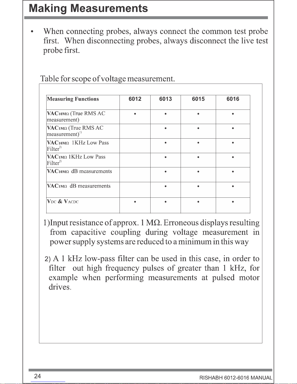
Voltage VDC (Ri>9M )
Voltage VAC TRMS (Ri>9M )
Voltage LoZ VAC TRMS (Ri=1M )
Voltage VAC TRMS (Ri>9M ) LPF 1kHz
Voltage LoZ VAC TRMS (Ri=1M ) LPF 1kHz
Voltage VACDC (Ri>9M )
High impedance, high bandwidth mV meas urement
Bandwidth VAC & mV ACDC
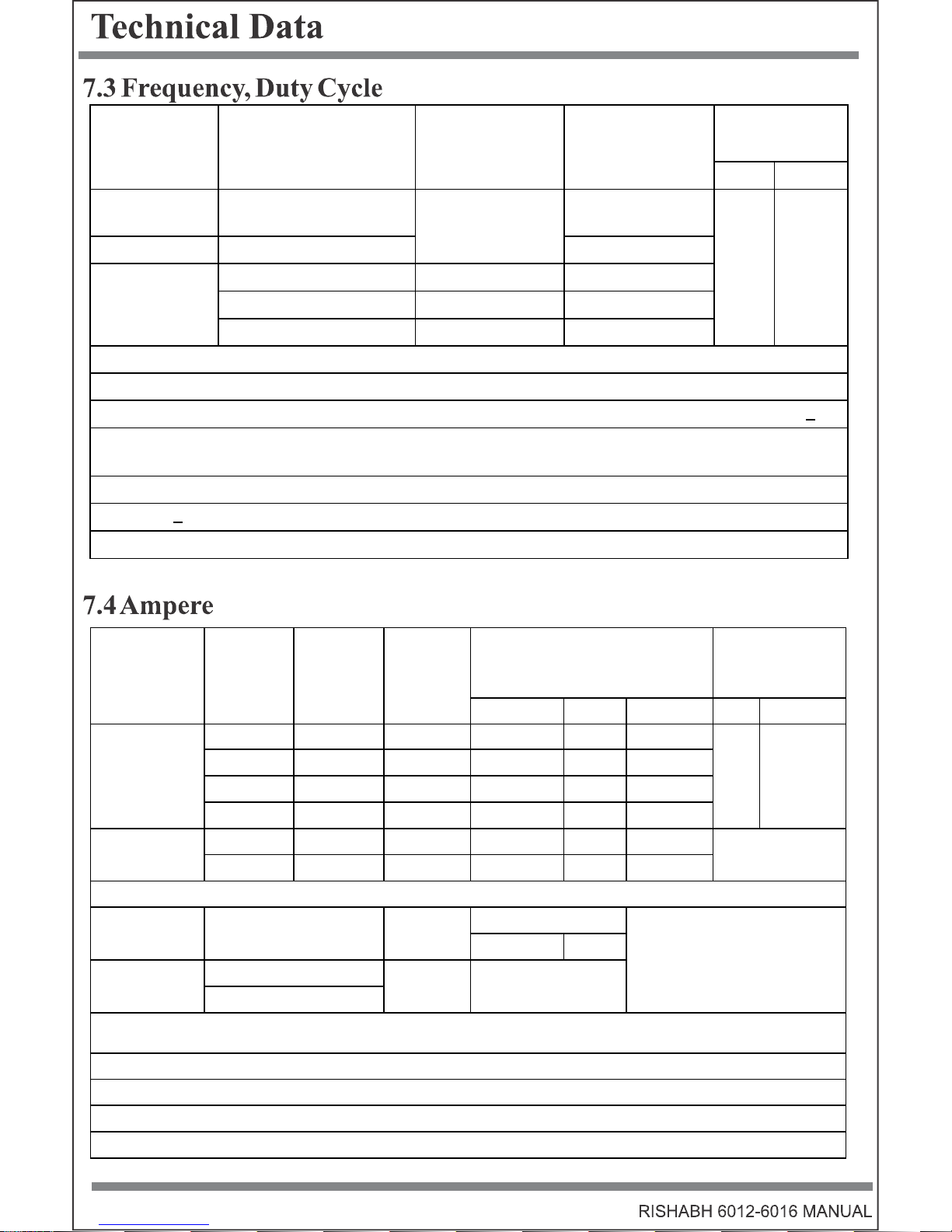
Frequency (Hz) Meas urement
Duty cycle %
Voltage level meas urement dB,dBu,dBm
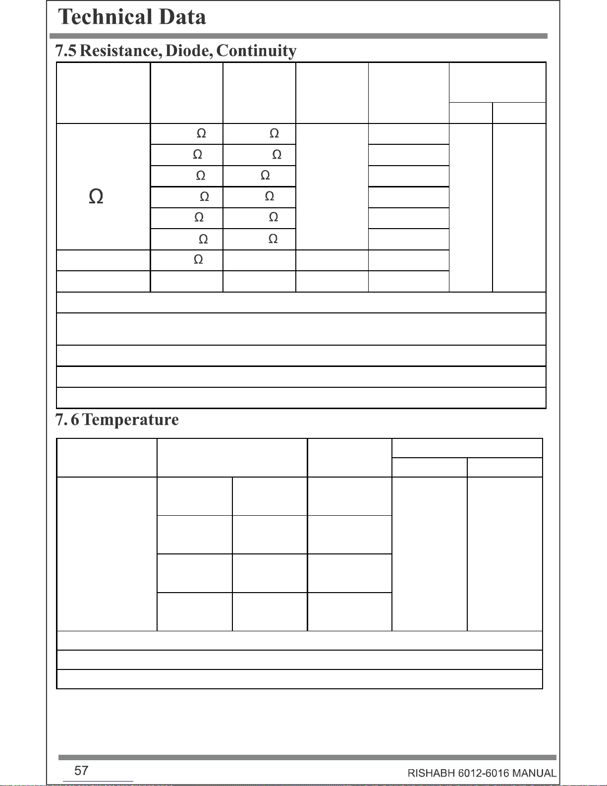
Resis tance
Conductance measurement
Continuity test (I cons t = 1 mA)
Diode m easurem ent (I const = 1 mA)
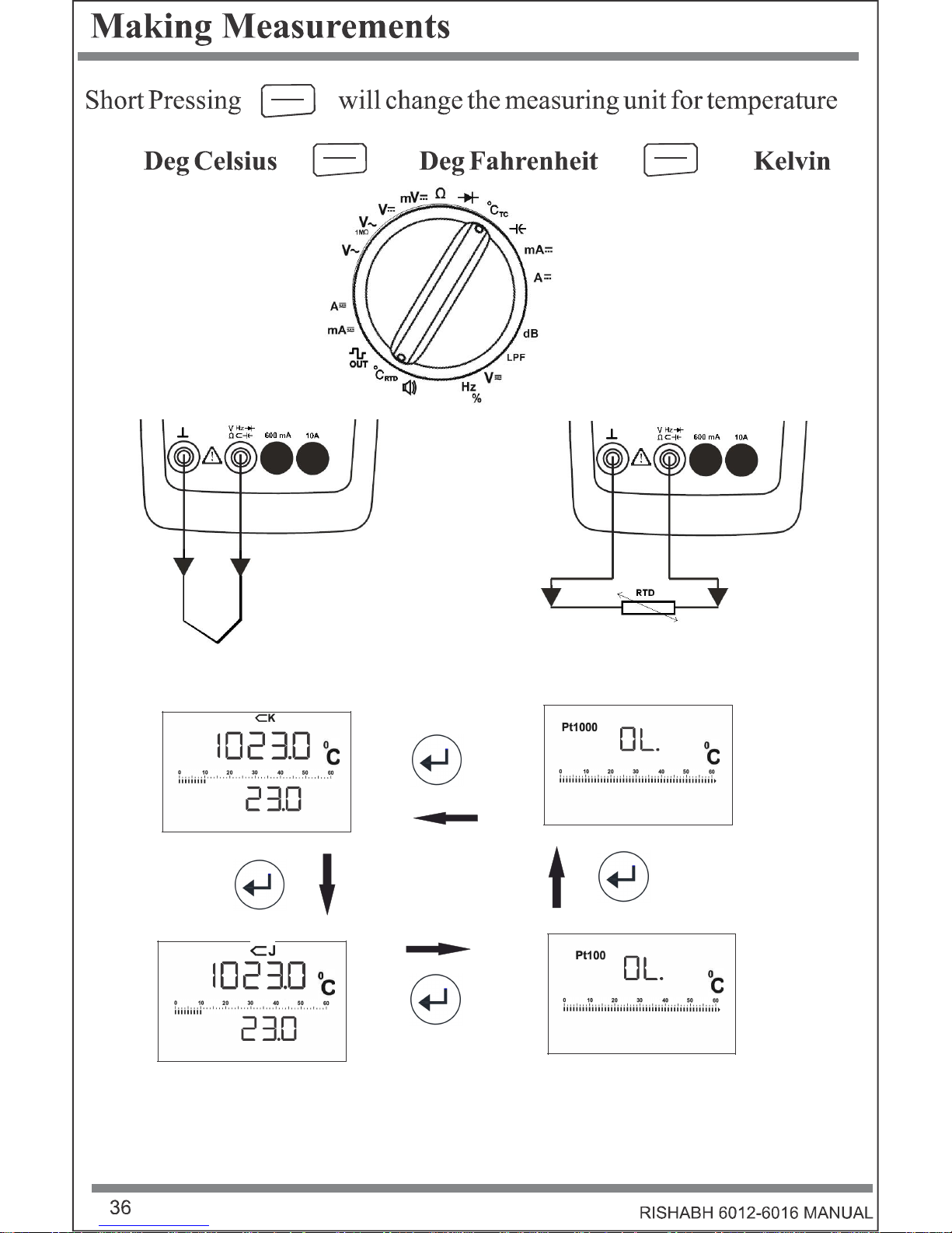
Temperature meas urement (TYP J,TYP K)
Temperature meas urement (PT100,PT1000)
Capacitance meas urement
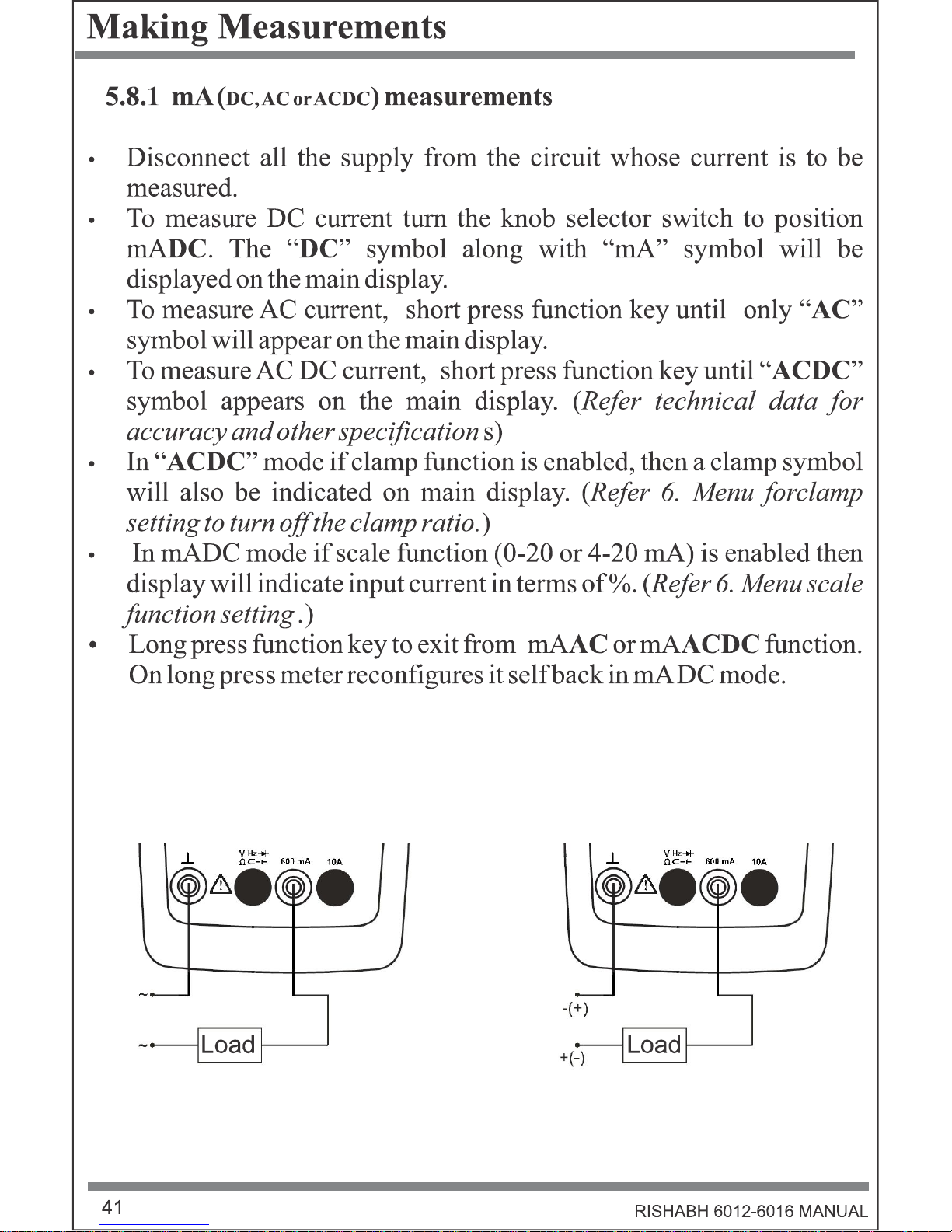
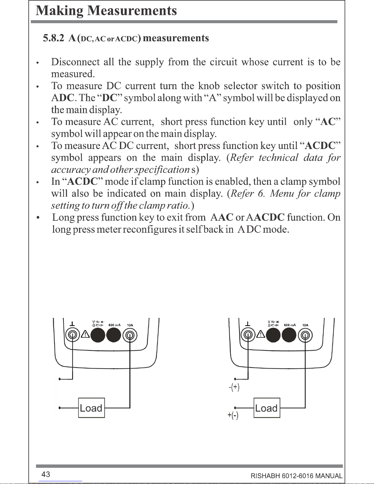
Current ADC
Current AAC+DC TRMS
Current AAC TRMS
Bandwidth @ AAC+DC or AAC 10 kHz
Meas urement with Clam p Sens or
Data Logging (upto 32000 readings) / Viewing Function
Protective rubber holster
Fuse 16A / 1000V
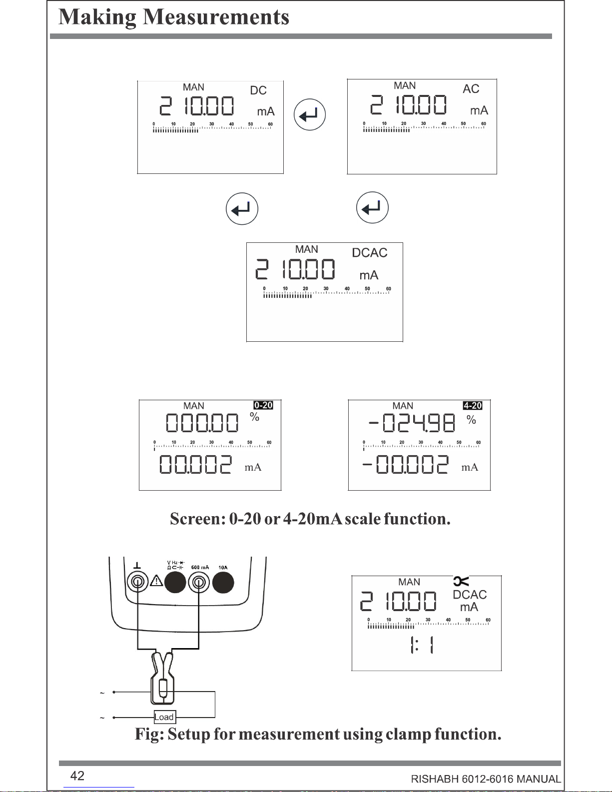
0-20mA / 4-20mA percentage s cale
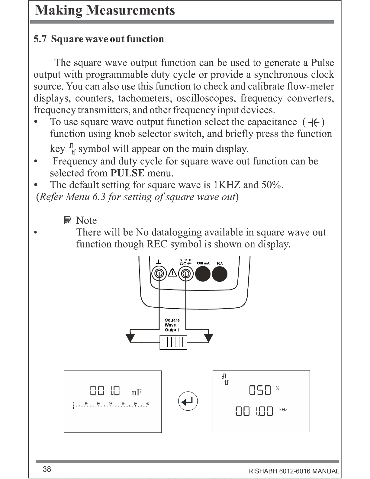
Square wave Out
Self batteryvoltage measurement
Fun ctions/Feature s 6012 6013 6015 6016
MIN/MAX/AVG and Auto Hold functions
Dangerous contact voltage indication
REL/Zero function
USB IR-interface
External power supply adapter
Meas uring Category
• • • •
• • • •
• • •
• • •
• • •
• • • •
• •
• • •
• • • •
• • • •
• • • •
• • • •
• • •
• • •
• •
• • • •
• • • •
• •
• • • •
• •
• •
• •
• • • •
• • • •
• • • •
• • • •
600mV
60mV/
600mV
60mV/600mV 60mV/600mV
10kHz 10kHz 10kHz 100 kHz
600mA 6 A/16 A
(20 A)
600 µA/6 mA
60 mA/ 600 mA
6 A/10 A (16 A)
600 µA/6 mA
60 mA/600 mA
6 A/10 A (16 A)
1.6A
Optional
1000 V
CAT III
600 V CAT
IV
1000 V
CAT I 600V
CAT II
1000 V CAT II I
600 V CAT IV
1000 V CAT II I
600 V CAT IV


Symbol Description Symbol Description
AC (Alternating
Current or Voltage)
DC (Direct Current
or Voltage)
Warning concerning a
point of danger (Refer
Manual)
Earth (ground)
terminal
Double or reinforced
insulation
Symbol Descri ption Symbol Description
AC (Alternating
Current or Voltage)
DC (Direct Current
or Voltage)
Warning concerning a
point of danger (Refer
Manual)
Earth (ground)
terminal
Double or reinforced
insulation
Measurements in
electrical circuits
which are electrically
connected to the low-
voltage mains:
with plugs, e.g. at
home, in the office or
laboratory etc.
Measurements in
building installations:
stationary power
consumers, distributor
terminals, devices
connected
permanently to the
distributor
Measurements at
power sources for
low-voltage
installations:
meters, mains
terminals, primary
overvoltage
protection devices
Fuse Hazardous Voltage
Measurements in
electrical circuits
which are electrically
connected to the lowvoltage mains:
with plugs, e.g. at
home, in the office or
laboratory etc.
Symbol Description Symbol Description
AC (Alternating
Current or Voltage)
DC (Direct Current
or Voltage)
Warning concerning a
point of danger (Refer
Manual)
Earth (ground)
terminal
Double or reinforced
insulation
Measurements in
electrical circuits
which are electrically
connected to the low-
voltage mains:
with plugs, e.g. at
home, in the office or
laboratory etc.
Measurements in
building installations:
stationary power
consumers, distributor
terminals, devices
connected
permanently to the
distributor
Measurements at
power sources for
low-voltage
installations:
meters, mains
terminals, primary
overvoltage
protection devices
Fuse Hazardous Voltage
Measurements in
building installations:
stationary power
consumers, distributor
terminals, devices
connected
permanently to the
distributor
Symbol Descri ption Symbol Description
AC (Alternating
Current or Voltage)
DC (Direct Current
or Voltage)
Warning concerning a
point of danger (Refer
Manual)
Earth (ground)
terminal
Double or reinforced
insulation
Measurements in
electrical circuits
which are electrically
connected to the low-
voltage mains:
with plugs, e.g. at
home, in the office or
laboratory etc.
Measurements in
building installations:
stationary power
consumers, distributor
terminals, devices
connected
permanently to the
distributor
Measurements at
power sources for
low-voltage
installations:
meters, mains
terminals, primary
overvoltage
protection devices
Fuse Hazardous Voltage
Measurements at
power sources for
low-voltage
installations:
meters, mains
terminals, primary
overvoltage
protection devices
Fuse
Hazardous Voltage

1
12
13
14
15
ON
AVG MIN
MAN
MAX
MAN
AUTO
ON
AUTO
dB
Hzk
n
Sm
AC
µ
DC
A
A
Mk
secmin
0
AVG
hr
0
0
0
MIN
0 4 6 0
5
1
MAX
%A
0
F2C
3
0A
AC
DC
0A
µ
n
K
INSU
JPAAAAt1000
Hz
µ
mV
INSU
%A
FC
0A0A
µ
n
0
0
0
00 4
5
10 2
3
K
JPAAAAt1000
Hz
µ
mVA
Mk
secminhr
Ω
ESC
AIN/MAX
AUTO
REL
HOLD
MENU
MANEXIT
2
3
4
5
6
7
8
9
10
11
1000V 1 6A

7
Operating Overview
The display at a glance
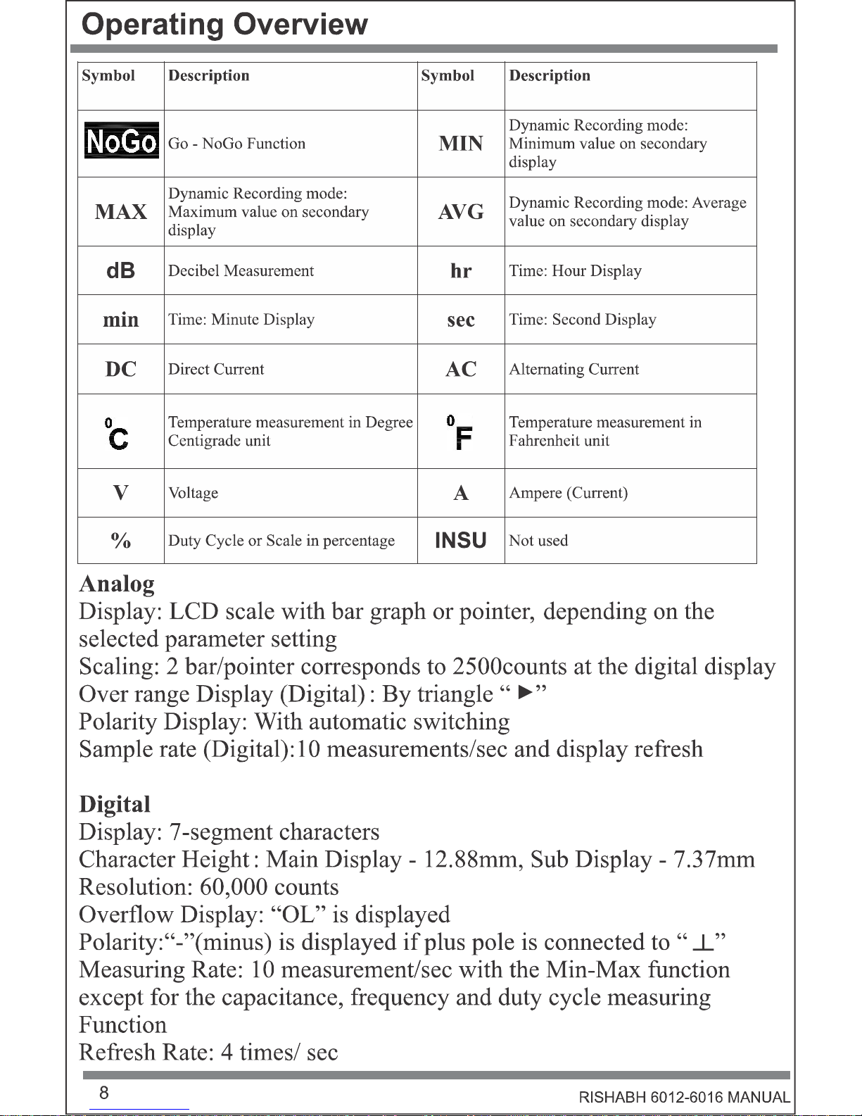
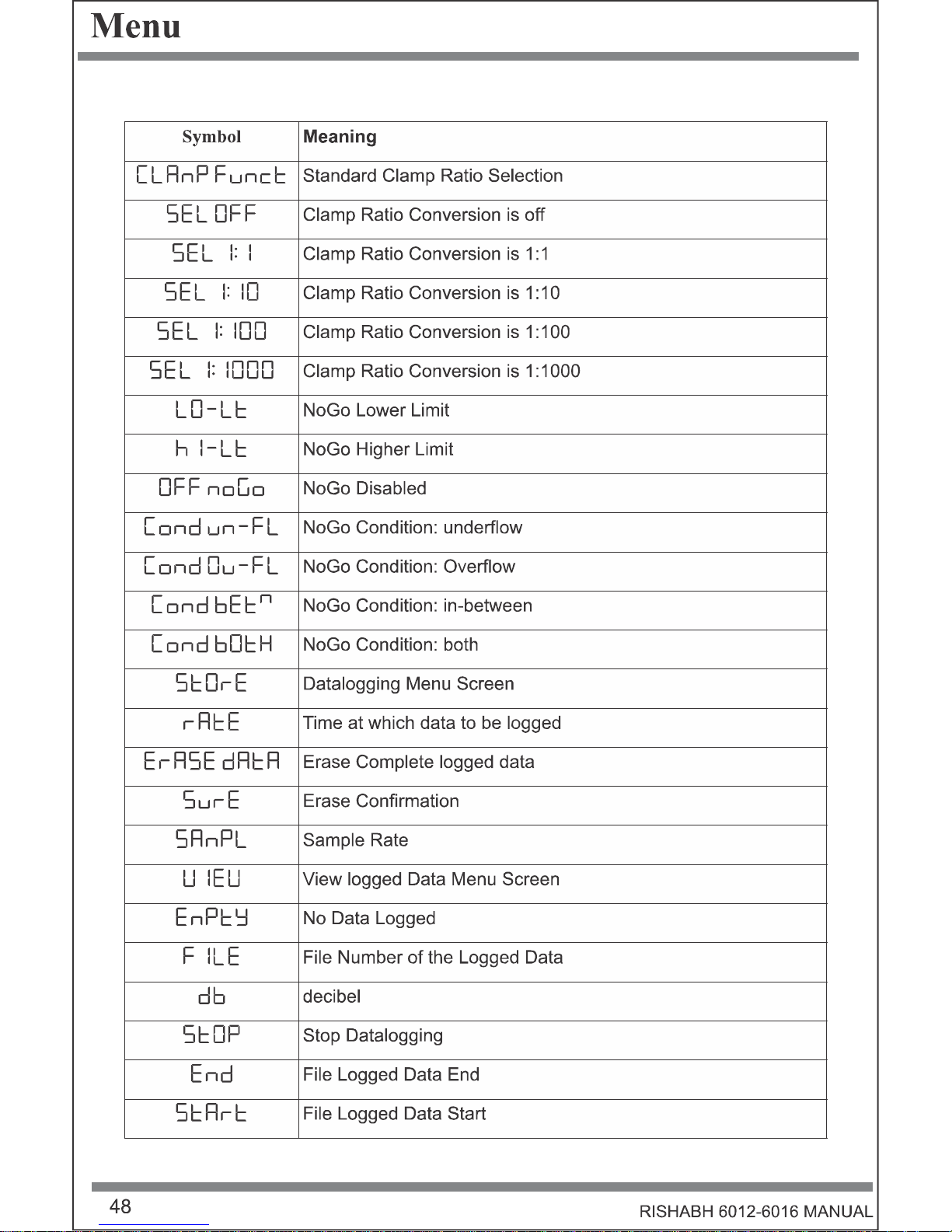
Symbol Description
Symbol Description
Low Battery Indication Continuous Meter on
AUTO Auto Range MAN
Manual Range Selection
Auto- Hold Enabled
Relative Measurement with reference
to offset
Percentage scale readout proportional
to DC 0–20 mA
Percentage scale readout
proportional to DC 4–20 mA
Standard Clamp Selected Presence of Hazardous Voltage
Audible Continuity
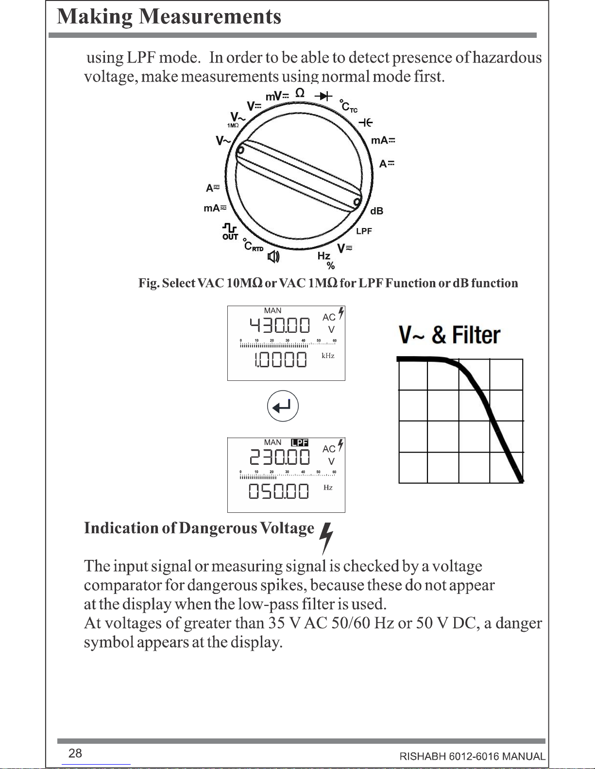
Low pass filter Cut-off Frequency
1kHz
Memory Data-Logging Indication View Logged Data
Square wave output
Diode
Thermocouple k Type Thermocouple J Type
RISHABH 6012-6016 MANUAL


AUTO
MAN
AUTO
MAN
AUTO
MAN


~
~


MENU
EXIT
MENU
EXIT
MENU
EXIT
MENU
EXIT
REL
ESC
REL
ESC
REL
ESC
REL
ESC
REL
ESC
REL
ESC
REL
ESC

MENU
EXIT
MENU
EXIT
MENU
EXIT
REL
ESC
REL
ESC
REL
ESC
REL
ESC
REL
ESC


6V 100µV
>9M
0.05 + 5
0.5 + 9 1 + 30
1000 V
DC/
AC
RMS
Sine
Continuous
60V 1mV 0.05 + 5
600V 10mV 0.05 + 9
1000V 100mV 0.09 + 10
60mV 1µV
>10G
0.09 + 15
- 1 + 30 Max 10 s
600mV 10µV 0.09 + 15
Frequency
>15 Hz....45 Hz 60 mV
~ , 600
3+30
>65 Hz....100kHz
>15 Hz....45 Hz
6V, 60V,
600V
2+9 3+9
> 65Hz… 1kHz 1+9 3+9
>1k Hz….. 20kHz 3+9
4+9
>20kHz….100kHz
3.5+30
>15 Hz....45 Hz
1000V
2+9 3+9
> 65Hz… 1kHz 2+9 3+9
>1k Hz….. 10kHz 3+30
1) Specified Accuracy is valid as of 3% of the measuring range.With Short- circuited test probes: residual value of
1 to 30 d at zero point due to the TRMS converter.
2) At 0°C to 40°C (Accuracy Range)
3) In VAC measurement, Frequency will be shown above 10% of
Me a surem e n t
Functi o n
Measuring
Ran g e
Resol uti on
In p u t
Im pe d a n
ce
Intri nsic Un certa i n ty under
Refe rence Con di tion ±(…% of
th e rd g .+…Digi ts)
Over l oa d Capa ci ty
DC AC ACDC
Val ue Tim e
V
m V
In fluence
Quanti ty
Ran g e of Influen ce Ran g e
Ac curacy
DMM
6016
Oth e rs
~
~
2)
7) 1) 3) 1) 3)
4)
the present range, ex cept for 1000V & 60mV
range i.e. 25% & 50% respectively.
4) Frequency Influence upto 10kHz.
5) Frequency response up to 50 kHz
6) Frequency response is valid from 10% to 100% of range
7) With Zero Balancing
8) Frequency response up to 100 kHz, for greater than 50 kHz plus 2.5%
9) Overload capacity of the voltage measurement input: power Limiting: Frequency x Voltage Max : 6x10 V x Hz
10) Frequency response greater than 2 kHz plus 2.5%
6)9)
5)
10)
8)
6
600Hz, 6KH z, 60KHz,
600 KHz, 1MHz
fm in : 6Hz
0.05 +5
100 0 V
DC/
AC
RMS
Sine
Max 10 s
10H z…..100 KHz
0.1 +5
2.0…98% 15H z .... 1kHz 0.1 R + 5 d
5.0…98% .... 10kHz 0.2 R per kHz + 5d
10…90% .... 50kHz 0.5 R per kHz + 5d
1) At 0°C to 40°C (Accuracy Range)
2) Lo w es t meas ura b le frequency for s quare m eas uring s ignals s ym metrical to the zero point ( 5V).
3) Overlo a d ca p a city of the voltage m eas urem ent inpu t :
Power lim iting : Frequency x voltage m a x : 6x10 V x Hz for U> 1 00V.
4) Input sens itivity, s inus o idal
Mea sure m en t
Fu ncti on
Mea suri ng Ra ng e Fre qu en cy
In trin sic
Un c erta i nty
Ov e rlo ad
Ca p aci ty
Hz
Hz(V)
Du ty Cycl e(%)
1)
5)
3)
Value Tim e
s ignal , 10% to 100 % of the m eas uring range
5) At input 5Vrm s ,Square wave, Bipolar inp uts .
R= Rang e d = d igit
2)
4)
6
+
+
600 µA 10 nA 60 m V 0.5 + 15 1 + 10 1.5 + 10
0.7A Continuous
6 mA 100 nA 60 mV 0.5 + 5 1 + 10 1.5 + 10
60 m A 1 µA 60 mV 0.1 + 5 1 + 10 1.5 + 10
600 m A 10 µA 60 mV 0.2 + 5 1 + 10 1.5 + 10
6 A 100 µA 60 mV 0.9 + 10 1 + 10 1.5 + 10
10 A: = 5 min
10 A 1 mA 300 mV 0.9 + 10 1 + 10 1.5 + 10
1) Specified Accuracy is valid as of 3% of the meas uring range. With Short- circuited tes t probes:
res idual value of 1 to 30 d at zero point due to the TRMS converter.
2) At 0°
Measure m en t
Function
Measuri n g
Range
Resoluti on
Votl ag e
Drop
Approx .
Intrinsic Uncerta i nty under
Refer e n ce Condi ti on ±(…% of
the rd g.+…Digi ts)
Ove rl o ad
Cap aci ty
DC AC ACDC
mA
A
2)
4) 1) 1)
Value Time
C to 40°C (Accuracy Range)
3) Off time 30 min and TA = 40°C
4) With Zero Balancing
5) Frequency res pons e is valid from 10% to 100% of range
3)
Influence
Quantity
Range of Influence Range
Accuracy
DMM 6016 Others
Frequency
>15 Hz....45 Hz
600µA......
10A
3+10
>65Hz....10 kHz
5)
56
M e a su r e m ent
Fu n c ti o n
M e a su r i n g Ra n g e
In tr i n si c
Un c e rt a i n ty
Ov e r l o a d Ca p a c i ty
1)
Va lu e Tim e
Te m p e ra t u re
°C/°F
Pt 1 0 0
-2 00 C ..
+8 5 0 °C
0 .3 + 1 5
10 00 V
D C/
AC
R MS
Sin e
Ma x 1 0s
Pt 1 0 0 0
-1 50 C ..
+8 5 0 °C
0 .3 + 1 5
TC K
-2 00 C ..
+1 3 7 2 °C
1 % + 20
TC J
-2 10 C ..
+1 2 0 0 °C
1 % + 20
1 ) At 0 °C to 4 0°C (Accu ra cy R an ge )
2 ) Plu s S en s o r D evia tio n
o
2)
o
2)
o
2)
o
2)
Measurem ent
Function
Measuring
Range
Resolution
Open Ckt.
Vol tage
Intrinsic
Uncertai nty
Overl oad
Capaci ty
Continui ty
Diode
4)
1)
1)
Value Time
600 10m
<1.4V
0.1 + 10
1000 V
DC/
AC
RMS
Sine
Max 10 s
6k 100m 0.1 + 10
60k 1 0.1 + 10
600k 10 0.5 + 10
6M 100 1 + 10
60M 10k 5 + 10
600 - Appx. 8V 3 + 5
6.0V
- Appx. 8V 0.5 + 5
1) Measurem ent of Resistance, Diode will be more accurate after removal from device
under test
2) At 0°C to 40°C (Accuracy Range)
3) Displays up to max 6.0 V, “OL” in excess of 6.0V.
4) With Zero Balancing
3)

M e a su r e m e n t
F u n c ti o n
M e a su r i n g
R a n g e
R e so l u ti o n
In tr i n si c
U n c e r ta in ty
O v e r l o a d
C a p a c i t y
F
V M A X
V al u e T im e
O
2)
3 )4)
1 0 n F 10 p F
0 .7 V
1 + 1 0
1 0 0 0 V D C /
AC R MS
S i n e
Ma x 1 0 s
1 0 0 n F 1 0 0 p F
1 + 6
1 µ F 1 n F
1 + 6
1 0 µ F 1 0 n F
1 + 6
1 0 0 µ F 1 0 0 n F
5 + 6
1 00 0 µ F 1 µ F
5 + 6
1 ) At 0 °C to 4 0°C (Ac cu ra c y R a n ge )
2 ) Ap p li es to m e a s u r em e n ts a t fi l m c a p a cito rs a n d b a tte ry o p e ra te d .
3 ) Me a s u r e m e n t o f C ap acita n c e w il l b e m o re a c c u r ate a fte r r em o va l fro m d e vi c e u n d e r te s t
4 ) W ith Z e ro B al a nci n g
2)
2)
2)
2)
2)
2)
Output Range Accura cy
Frequency 30Hz - 10kHz 0.1% x output frquency + 2 counts of DMM dis play
Duty Cycle
10% - 90% 0.2% of Full s cale
Am plitude Fixed -3.15 to 3.15V ±0.4V
1) For signal greater than 1kHz, add 0.2% per kHz to the accuracy
2) In Multiple of 10
[2] [1]
Tem perature -10 ºC to 21 ºC & +25 °C to 50 °C
VDC 0.2 + 20
V ~, VACDC 0.4 + 10
600 to 600 k 0.5 + 10
> 600 k 1.5 + 10
mA / ADC 0.6 + 10
mA / A AC, ACDC 0.8 + 10
10nF…10µF 1 + 5
100µF...1000µF 1.5+10
Hz, Duty Cycle 0.2 + 10
ºC/ºF pt100/pt100 0.5 + 10
ºC/ºF therm ocouple
K/J
0.2 + 10
Relative humidity
75%
3 Days
Influenc e Quantity Range of Influence
Measur ed Quantity /
Measur ing Range
Var iation ± (….%of rdg. +
….digits)/10K
1)
Meter off
V~,V DC, A AC+DC,A
DC, F, Hz, °C, %,
1 × intrins ic error
1) With Zero Balancing

Technical Data
Influ e nce Quan t it y Rang e o f In f lu ence Meas ur ing Rang es A t ten u ation
Co mmon Mo d e i nter fer ence
vo l tag e
No r mal Mo d e
in ter fer ence r ati o
Noise quantit y max. 1000 V dc V dc > 120 dB
Noise quantity max. 1000 V ~
50-60 HZ sinusoidal
6.0 V~,60 V~ >80 dB
600 V~ > 70 dB
1000 V~ > 60 dB
Noise quantity V ~
Value of t he measuring range at a
tim e
Max. 1000V~ , 50Hz, 60Hz
Sinusoidal
V dc > 50dB
Noise quantit y max. 1000 V dc V~ >110dB
RISHABH 6012-6016 MANUAL
EMC Immunity IEC 61326-1:2012, Table A.1
Immunity IEC 61000-4-2 : 8 KV atmosphere discharge, 4 KV contact discharge
IEC 61000-4-3 : 3 V/m
Safety IEC 61010-1-2010
IP for water & dust IEC 60529
Pollution degree 2
Installation category
1000 V CATIII / 600 V CATIV, 600V CATII for DMM 6013
High Voltage Test
7.4 kV (IEC 61010-1-2010), 3.5kV For DMM 6013
Test & Procedure IS 13875
Operating Temperature
Storage Temperature
Relative Humidity
IP
Altitude
-10 to +50 C
o
-20 to +70 C
o
<75% non condensing
IP 50 for Housing, IP 20 for Terminal
Up to 2000m

Technical Data
Time Format dd.MM.yy hh.mm.ss
Resolution 1 s
Accuracy
Temperature Influence
+1min. per month
50 ppm/K
RISHABH 6012-6016 MANUAL
0 10000 20000 30000 40000 50000 60000
0
2
4
6
8
10
Displayed Value [Counts]


2-60-006-00-00607
Rev C: 05/07/2017
 Loading...