


ENGLISH
GENERAL DESCRIPTION
The NOVA 90 is a microprocessor based wireless Passive Infra Red (PIR)
detector, powered by an internal, long life, 3V, lithium battery:
It includes the following PIR features:
❐ Microprocessor Design
❐ True Temperature Compensation
❐ Adjustable Pulse Count.
❐ Wide & Long Range Lenses
❐ Creep Zone
❐ Vertical Adjustment
❐ Protective Sleeve for Sensor
❐ Self Test
ITALIANO
DESCRIZIONE GENERALE
NOVA 90 è un rivelatore all’infrarosso passivo controllato da microprocessore,
alimentato con una batteria interna 3 Volt al litio a lunga autonomia.
Caratteristiche Sensore Infrarosso
❐ Controllato da Microprocessore
❐ Compensazione Reale della Temperatura
❐ Conteggio Impulsi Programmabile
❐ Lenti Grand’angolo e a Lunga Portata
❐ Protezione Verticale (anti-strisciamento)
❐ Regolazione Verticale
❐ Protezione dell’ottica del Sensore
❐ Auto Test
FRANÇAIS
DESCRIPTION GENERALE
Le NOVA 90 est un détecteur infrarouge passif radio géré par microprocesseur,
utilisant une pile lithium interne de 3 Volts.
Les caractéristiques de l'infrarouge :
❐ Gestion par microprocesseur
❐ Compensation de température
❐ Comptage d'impulsions réglable
❐ Lentilles grand angle ou longue portée
❐ Détection verticale
❐ Ajustement vertical de la carte
❐ Protection optique du capteur
❐ Auto test
DEUTSCH
ALLGEMEINE BESCHREIBUNG
Der NOVA 90 Funk-Bewegungsmelder arbeitet mit Mikroprozessor-T echnologie
und wird von einer 3V Lithiumbatterie mit Strom versorgt.
PIR-Merkmale :
❐ Mikroprozessor-Technik
❐ Automat. Temperaturabhängige Empfindlichkeitsanpassung
❐ Impulswahlmöglichkeit einstellbar
❐ Kriechzone
❐ Vertikale Einstellmöglichkeit
❐ Gekapselter Sensor
❐ Selbstetst
ESPAÑOL
DESCRIPCION GENERAL
El NOVA 90 es un detector Infrarrojo Pasivo (PIR) inalámbrico basado en
microprocesador, alimentado por una batería interna de litio de larga vida de
3V.
El PIR tiene las siguientes características:
❐ Diseño con microprocesador
❐ Compensación Verdadera de Temperatura
❐ Contado de Pulsos Ajustable
❐ Lentes: de Gran Angulo y de Largo Alcance
❐ Zona de Sabotaje
❐ Ajuste Vertical
❐ Manguito Protector del Sensor
❐ Auto-prueba
WIRELESS Features
❐ The NOVA 90 functions in four modes of operation: NORMAL,
FULL SIGNALING, WRITE, FAST MONITORING (not available for FCC)
❐ The unit uses one of more than 16 million code addresses for its setup (no
DIP switches)
❐ An extended battery life.
❐ Fully and automatically monitored and supervised
OPERATIONAL MODES
The NOVA 90 can be configured to operate in the following four modes:
Caratteristiche RADIO
❐ Quattro modi operativi differenti: NORMALE, SEGNALAZIONE COMPLETA,
MODO INDIRIZZAMENTO (WRITE), MONITORAGGIO VELOCE (non
disponibile per la versione FCC)
❐ L’unità ha un codice d’identificazione univoco pre-programmato in fabbrica
e selezionato casualmente tra 16 milioni di codici (Autoapprendimento)
❐ Lunga autonomia della batteria.
❐ Completamente e Automaticamente monitorato e supervisionato
MODI OPERATIVI
NOVA 90 può essere configurato per operare nei 4 modi seguenti:
Les caractéristiques radio :
❐ Le NOVA 90 possède quatre modes de fonctionnement :
NORMAL, TEST DE PASSAGE, ADRESSAGE et SUPERVISION RAPIDE
❐ Pendant l'adressage, le détecteur choisit une adresse parmi plus de 16
millions de combinaisons. (Pas de micro-interrupteur)
❐ L'autonomie de la pile est plus longue.
❐ Le détecteur est totalement et automatiquement supervisé
MODES DE FONCTIONNEMENT
Le NOVA 90 peut être configuré pour fonctionner dans les quatre modes
suivants :
FUNK-Merkmale
❐ Der NOVA 90 kann mit den vorhandenen Steckbrücken auf 4
Funktionsbereiche programmiert werden : NORMAL, GEH-TEST,
SCHNELLEÜBERWACHUNG und WRITE.
❐ Anzahl der Code : über 16.000.000
❐ Lange Batteriedauer ( 5 Jahre / Normal-Modus )
❐ Automatische Überwachung des Funkbereiches
FUNKTIONSBEREICHE
Der NOVA 90 kann auf 4 Funktionsbereiche programmiert werden :
Características de radio
❐ El NOVA 90 funciona en cuatro modos de operación:
NORMAL, SEÑALIZACION COMPLETA, PROGRAMACION, MONIT OREO
RAPIDO
❐ La unidad utiliza uno de entre más de 16 millones de códigos preprogramados
(no utiliza microinterruptores)
❐ Vida de batería extendida
❐ Completa y automáticamente monitoreado y supervisado
MODOS DE OPERACION
El NOVA 90 puede ser configurado para operar en uno de los cuatro modos
siguientes:
NORMAL - 2.5 minutes dead time between detections and a Supervisory /
Monitoring message provided every 65 minutes, giving the status of the alarm
and battery.
FULL SIGNALING - No dead time between detections (recommended for
test & installation).
FAST MONITORING – The unit will send every 12 minutes a Supervisory /
Monitoring message. This feature is not available for FCC.
WRITE –The unit transmits a WRITE message each time the Tamper Switch
is pressed for at least 3 seconds.
NORMALE - tempo di blocco trasmissioni di 2.5 minuti tra le rilevazioni e la
Supervisione/Monitoraggio che viene trasmessa ogni 65 minuti insieme allo
stato del sensore e della batteria.
SEGNALAZIONE COMPLETA – Nessun tempo di blocco trasmissioni tra le
rilevazioni del sensore (consigliato per l’installazione ed il test).
MONITORAGGIO VELOCE – L’unità trasmette ogni 12 minuti il messaggio
di Supervisione / Monitoraggio. Questa caratteristica non è applicabile alla
versione FCC del rivelatore.
INDIRIZZAMENTO (WRITE) – L’unità trasmette un messaggio di INDIRIZZO
(WRITE) ogni qualvolta l’interruttore tamper viene premuto per almeno 3
secondi.
NORMAL - 2,5 minutes d'inhibition entre chaque détection et un message de
supervision produit toutes les 65 minutes, donnant l’état général de l’alarme
et de la pile.
TEST DE PASSAGE: Pas d'inhibition entre les détections pour permettre les
tests pendant l'installation.
SUPERVISION RAPIDE: Le détecteur enverra toutes les 12 minutes un
message de supervision.
ADRESSAGE: Pour adresser le détecteur au récepteur, il faudra appuyer sur
la barrette d'autoprotection pendant au moins 3 secondes.
NORMAL - mit 2,5 Min. Ruhezeit zwischen den Erfassungen. Die
Funküberwachung wird je 65 Minuten durchgeführt.
GEH-TEST - Keine Ruhezeit zwischen den Erfassungen ( der Sender wird
nach jeder Erfassung aktiviert ).
SCHNELLEÜBERWACHUNG : Die Funküberwachung wird je 12 Minuten
durchgeführt.
WRITE - Sendet immer eine Programmiernachricht wenn der Sabotagekomtakt
für 3 Sek. aktiviert wird.
NORMAL – 2.5 minutos de “tiempo muerto” entre detecciones y un mensaje
de Supervisión/Monitoreo provisto cada 65 minutos, comunicando el estado
de alarma y batería.
SEÑALIZACION COMPLETA – no hay “tiempo muerto” entre detecciones
(recomendado para pruebas e instalaciones).
MONITOREO RAPIDO – La unidad enviará cada 12 minutos un mensaje de
Supervisión/Monitoreo.
WRITE (PROGRAMACION) – La unidad transmite un mensaje de WRITE
cada vez que el interruptor de Tamper (autoprotección) es presionado por lo
menos por 3 segundos.
LED INDICATION
❐ After each detection, the LED lights up for a few seconds.
❐ On LOW Battery condition, the LED will blink during each transmission.
INSTALLATION PROCEDURE
STEP 1 - PRELIMINARY CONSIDERATIONS
Before installation, study carefully the space to be protected in order to choose
the exact location of the unit and the suitable lens for best coverage.
INDICAZIONI DEL LED
❐ Il LED dell’unità s’illumina per qualche secondo dopo ogni rilevazione.
❐ In condizione di Basso Livello Batteria, il LED dell’unità lampeggia durante
ogni trasmissione.
PROCEDURA D’INSTALLAZIONE
PASSO 1 – CONSIDERAZIONI PRELIMINARI
Prima dell’installazione studiare attentamente il luogo da proteggere per
scegliere l’esatta posizione dell’unità a garanzia di una copertura volumetrica
efficiente.
INDICATION DE LA LED
❐ Après chaque détection, la LED s'allume pendant quelques secondes.
❐ Si la pile est faible, la LED clignotera à chaque transmission.
❐ Il est recommandé de ne pas utiliser la LED en Mode Normal, de façon à
économiser la pile.
PROCEDURE D'INSTALLATION
Etape 1 - Considérations préliminaires
Avant de procéder à l'installation, étudiez attentivement la zone à protéger de
manière à choisir l'emplacement approprié pour le détecteur en fonction de sa
lentille, afin d'obtenir la meilleure couverture possible.
LED – ANZEIGE
❐ leuchtet nach jeder Erfassung ein paar Sekunden auf
❐ im Falle einer Low-Battery –Erkennung, blinkt die LED während jeder
Übertragung 3 mal.
INSTALLATION
Schritt 1 - VORABENTSCHEIDUNGEN
Bevor Sie mit der Installation des PIR-Melders beginnen, sollten Sie den Raum,
der geschützt werden soll, genau besichtigen, um den Einbauort des PIRMelders und die Linse, die Ihnen die beste Erfassung ermöglicht, zu wählen.
INDICACION DEL LED
❐ Luego de cada detección, el LED se enciende por unos segundos.
❐ Si existe una condición de Batería Baja, el LED parpadea durante cada
transmisión.
PROCEDIMIENTO DE INSTALACION
PASO 1 - CONSIDERACIONES PRELIMINARES
Antes de efectuar la instalación, estudiar cuidadosamente el espacio a ser
protegido con el objeto de seleccionar la ubicación exacta de la unidad y la
lente correspondiente para conseguir la mejor cobertura.
CAUTION: THE UNIT SHOULD NOT BE MOUNTED IN DIRECT SUNLIGHT
OR NEAR HEAT SOURCES. THE DETECTION SECTORS SHOULD BE
POINTED TOWARDS EITHER A WALL OR THE FLOOR (NOT WINDOWS,
CURTAINS, ETC.). LOCATIONS NEAR METAL OBJECTS SHOULD ALSO
BE AVOIDED SINCE THEY INFLUENCE THE COMMUNICATION
CAPABILITIES OF THE TRANSMITTER.
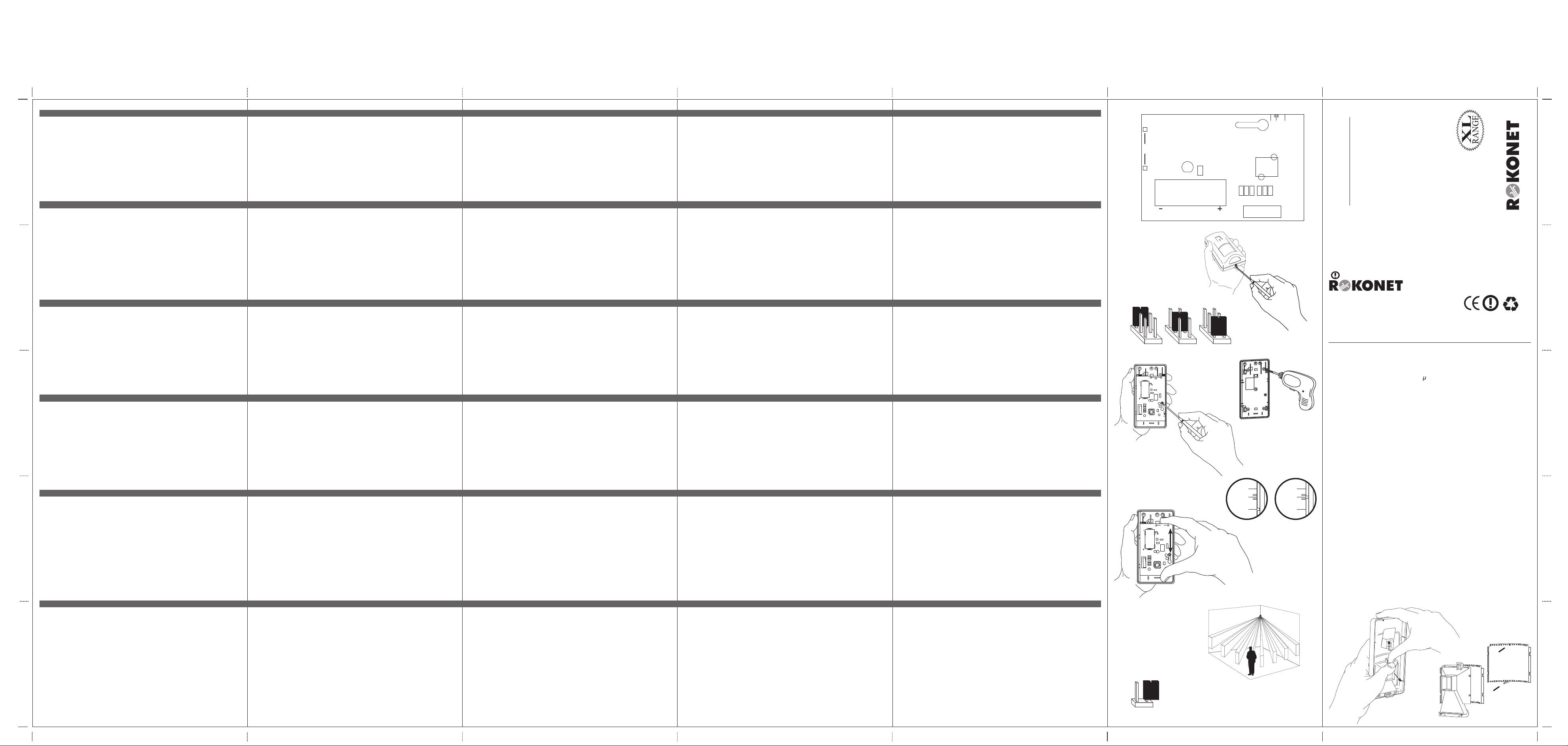
STEP 2 – FRONT COVER REMOVAL
Front cover removal (fig. 2).
ATTENZIONE: L’UNITA’ NON DEVE ESSERE MONTATA DI FRONTE ALLA
LUCE SOLARE DIRETTA O VICINO A SORGENTI DI CALORE. L’UNITA’
DEVE ESSERE ORIENTATA VERSO PARETI O PAVIMENTI (NO VERSO
FINESTRE, TENDE, ETC.). DEVE ANCHE ESSERE EVITATO IL
POSIZIONAMENTO IN PROSSIMITA’ DI OGGETTI METALLICI POICHE’
QUESTI ULTIMI POTREBBERO CAUSARE INTERFERENZE O RIDURRE
LA CAPACITA’ DI COMUNICAZIONE RADIO DEL RIVELATORE.
PASSO 2 – RIMOZIONE DEL COPERCHIO FRONTALE
Rimozione coperchio frontale (fig. 2).
ATTENTION: CET APPAREIL NE DEVRA PAS ETRE INSTALLE EN PLEIN
SOLEIL, NI A PROXIMITE D’UNE SOURCE DE CHALEUR. LES FAISCEAUX
DE DETECTION DOIVENT ETRE DIRIGES VERS UN MUR OU VERS LE
SOL (JAMAIS VERS UNE FENETRE, DES RIDEAUX, ETC…)
UN EMPLACEMENT A PROXIMIE D’OBJETS CONDUCTEURS DEVRA ETRE
EVITE POUR NE PAS INTERFERER AVEC LES TRANSMISSIONS.
Etape 2 - Démontage de la face avant
Pour cette étape, reportez-vous à la figure 2.
ACTUNG: DER PIR-MELDER DARF WEDER DIREKTEM SONNENLICHT
ODER AUTO-SCHEINTERFERN AUSGESETZT , NOCH IN DER NÄHE EINER
WÄRMEQUELLE INSTALLIERT WERDEN. DIE ERFASSUNGSBEREICHE
SOLLTEN ENTWERDER GEGEN EINE WAND ODER AUF DEN BODEN
AUSGERICHTET WERDEN (KEINE FENSTER ODER VORHÄNGE). DER
MONTAGEORT DARF SICH NICHT IN DER NÄHE VON
METALLGEGENSTÄNDEN, WELCHE DIE FUNKÜBER TRAGUNG STÖREN
KÖNNTEN, BEFINDEN.
Schritt 2 – ETFERNEN DES GEHÄUSEDECKELS
Entfernen des Gehäusedeckels (fig. 2).
ATENCION: LA UNIDAD NO DEBE SER MONTADA FRENTE A LA LUZ DEL
SOL DIRECTA O CERCA DE FUENTES DE CALOR. LOS SECTORES DE
DETECCION DEBEN SER DIRIGIDOS HACIA UNA PARED O EL PISO (NO
HACIA VENTANAS, CORTINAS, ETC.). ASIMISMO, DEBE EVITARSE
UBICARLA CERCA DE OBJET OS DE METAL YA QUE EST OS INFLUENCIAN
LA CAPACIDAD DE COMUNICACION DEL TRANSMISOR.
PASO 2 - REMOVIENDO LA CUBIERTA
Removiendo la cubierta (fig. 2).
STEP 3 – TRANSMITTER/ RECEIVER COMMUNICATION SETUP
The NOVA 90 must identify itself to the system’s receiver by writing its coded
message into the receiver’s address memory. This is accomplished by performing
the following steps:
1. Set the receiver to Write Mode.
2. Remove the battery from the insulation material.
3. Send a WRITE message pressing the tamper switch for at least 3 seconds.
Verify that the NOVA 90 has been identified by the receiver.
4. Set the receiver to NORMAL mode.
5. Set MODE jumpers to FULL SIGN, LED jumper to ON and PULSE to any
desired count, 1, 2 or 3 (see fig. 1 & 3 ).
PASSO 3 – CONFIGURAZIONE DEL TRASMETTITORE / RICEVITORE
NOVA 90 deve essere identificato dal sistema ricevente trasmettendo il proprio
indirizzo nella memoria del ricevitore. Questa operazione viene effettuata
eseguendo la procedura seguente:
1. Predisporre il ricevitore nel Modo Indirizzamento (write).
2. Rimuovere la plastica di protezione dalla batteria del NOVA 90.
3. Trasmettere l’indirizzo del NOVA 90 al ricevitore premendo l’interruttore
tamper per almeno 3 secondi. Verificare che il NOVA 90 è stato identificato
dal ricevitore.
4. Predisporre il ricevitore nel Modo Normale di Funzionamento.
5. Predisporre i ponticelli MODE del NOVA 90 in Modo Segnalazione Completa
(FULL SIGN), il ponticello di abilitazione LED in ON (Inserito) ed il ponticello
del conteggio impulsi (PULSE) sul conteggio impulsi desiderato, 1, 2 o 3
(consultare le fig. 1 e 3)
Etape 3 - Adressage du NOVA 90 au récepteur NOVA
Le récepteur fonctionnant avec le NOVA 90 doit pouvoir reconnaître le code
du détecteur, pour cela, vous allez adresser le NOVA 90 en suivant les
instructions ci-dessous:
1. Placez les barrettes du récepteur en Mode Adressage.
2. Retirez le film protecteur de la pile du détecteur
3. Envoyez un message d'adresse en appuyant sur l'autoprotection du détecteur
pendant au moins 3 secondes. Vérifiez que le NOVA 90 a bien été identifié
par le récepteur.
4. Repositionnez le récepteur en Mode Normal.
5. Sur le détecteur, placez le cavalier Mode sur FULL SIGN (Test de Passage),
le cavalier LED sur ON et le cavalier PULSES (impulsions) sur le comptage
désiré 1, 2 ou 3 (voir figures 1 et 3).
Schritt 3 - SENDER / EMPFÄNGER KOMMUNIKATIONS-SETUP
Der NOVA 90 muß in das System eingelernt werden. Um den Melder einzulernen,
unternehmen Sie bitte folgende Schritte :
1. Setzen Sie den Empfänger in den Programmier-Modus(Write).
2. Isolationsmaterial von der Batterie entfernen.
3. Halten Sie den Deckelkontakt des Senders für mehr als 3 Sek. gedrückt,
um eine Programmiernachricht zu senden. Prüfen Sie ob den Melder
eingelernt wurde.
4. Setzen Sie den Empfänger auf Normal-Modus.
5. Stecken Sie den MODE-Stecker auf „FULL SIGN“ Position, den LED-Stecker
auf „ON“ und den PULSE-Stecker auf eine beliebige Impulszahl 1,2, oder
3 ( fig. 1 & 3 ).
PASO 3 - PREPARACION DE TRANSMISOR / RECEPTOR
El NOVA 90 debe identificarse ante el receptor del sistema escribiendo su
mensaje codificado en la memoria del receptor. Esto es conseguido realizando
los siguientes pasos:
1. Colocar el receptor en Modo Write.
2. Remover la batería del material aislante.
3. Enviar un mensaje Write presionando el interruptor de autoprotección
(tamper) por lo menos por 3 segundos. Verificar que el NOVA 90 ha sido
identificado por el receptor.
4. Colocar el receptor en Modo Normal.
5. Colocar los puentes de MODO en posición FULL SIGN, el puente del LED
en ON y el de pulsos al número deseado, 1, 2 o 3 (ver fig. 1 y 3).
STEP 4 – SELECTION OF INSTALLATION LOCATION
1. Select a location best suited for communication quality and coverage, and
temporarily attach
2. Generate an ALARM signal and verify that the receiver has received the
signal.
the unit to this point using two sided adhesive tape.
STEP 5 – FINAL MOUNTING
Loosen the PCB’s holding screw and slide the PCB up until the screw head
is located in the round hole thus allowing removal of the PCB (see fig. 4 ).
1. Open knockout holes (see fig. 5).
2. Mount the detector into its final position.
3. Reinstall the PCB.
PASSO 4 – SCELTA DELLA POSIZIONE D’INSTALLAZIONE
1. Scegliere una posizione che ben si adatta sia alla copertura volumetrica
della lente del sensore, sia alla qualità di comunicazione della parte
trasmittente. Fissare temporaneamente l’unità usando, ad esempio, del
nastro biadesivo.
2. Generare un ALLARME e verificare la corretta ricezione dell’allarme da parte
del ricevitore.
PASSO 5 – INSTALLAZIONE FINALE
Allentare la scheda elettronica del rivelatore svitando la vite di fissaggio della
scheda e muovendo la scheda fino a sfilarla. Non è necessario svitare la vite
completamente. (vedere fig. 4 ).
Etape 4 - Installation et localisation
1. Choisissez le meilleur emplacement pour une bonne transmission et une
excellente qualité de couverture. Fixez temporairement le détecteur au mur
avec un adhésif double face.
2. Provoquez un signal d'alarme et vérifiez que le récepteur a bien reçu le
signal.
Etape 5 - Montage final
Pour ôter la carte, desserrez la vis et faites glisser la carte afin que la vis soit
au niveau de la perforation et soulevez le circuit imprimé. (Voir figure 4)
1. Percez des trous dans la base (voir figure 5)
2. Montez la base en position finale au mur.
3. Installez à nouveau la carte
Schritt 4 - AUSWAHL DES MONTAGEORTES
1. Wählen Sie den optimalen Montageort des Melders, um eine sehr gute
Erfassung und störungsfreie Kommunikation zu ermöglichen. Befestigen
Sie den Melder vorübergehend mit einem doppelseitigen Klebeband.
2. Erzeugen Sie nun ein Alarmsignal und kontrollieren Sie den Empfang des
Alarmsignals durch den Empfänger.
Schritt 5 - ENDGÜLTIGE MONTAGE
Locken Sie die Platinen-Befestigungschraube und schieben Sie die Platine
soweit nach unten , bis die Schraube das Rundloch erreicht. Die Platine kann
nunmehr entfernt werden.
1. Durchbrochen Sie die vorgesehenen Durchbruchsmöglichkeiten ( fig. 5 ).
STEP 4 – SELECCION DE LA UBICACION DE INSTALACION
1. Elegir la mejor ubicación posible para asegurar calidad de comunicación
y cobertura, y ubicar la unidad temporariamente en su lugar utilizando cinta
adhesiva.
2. Generar una señal de ALARMA y verficar que el receptor ha recibido la
señal.
PASO 5 – MONTAJE FINAL
Aflojar el tornillo que sujeta la tarjeta y deslizar a ésta hasta que la cabeza del
tornillo quede frente al agujero redondo para permitir remover la tarjeta (ver
fig. 4).
1. Abrir los agujeros premarcados (ver fig. 5).
PORTUGUÊS
DESCRIÇÃO GERAL
O NOVA 90 é um detector Infra Vermelho Passivo (PIR) sem fios (WIRELESS),
microprocessado, equipado com uma pilha de Lithium de 3V, de longa
durabilidade.
O detector possui as seguintes características de PIR:
❐ Baseado em Microprocessador
❐ Compensação Real de Temperatura (Temperaturas baixas e altas)
❐ Contador de Pulsos Ajustável
❐ Lentes de Grande Angular e de Longo Alcance
❐ Zona de Rastejo (“Zona Zero”)
❐ Ajuste Vertical
❐ Manga Protetora do Sensor
❐ Auto Teste
Características “Sem Fios”
❐ O NOVA 90 funciona em quatro modos operacionais:
NORMAL; FULL SIGNALING (Sinalização Total); WRITE (gravação), F AST
MONITORING (monitoração rápida) (não disponível para FCC);
❐ O aparelho usa um dos mais de 16 milhões de códigos de endereçamento
para a sua identificação (não há jumpers ou DIP switches)
❐ Durabilidade prolongada da pilha
❐ Supervisão total, monitorada automaticamente
MODOS OPERACIONAIS
O NOVA 90 pode ser configurado para operar de acordo com uma dos seguintes
modos:
NORMAL - Intervalos de 2,5 minutos entre as detecções, com supervisão
e com envio de mensagem de monitoração efetuados a cada período de 65
minutos, informando o estado (status) do alarme e da pilha.
FULL SIGNALING (Sinalização Total) - Sem intervalos entre detecções.
(recomendado nos testes de instalação).
FAST MONITORING (Monitoração Rápida) – A supervisão e o envio de
mensagem de monitoração ocorrem a cada 12 minutos. (Está função não está
disponível para o FCC).
WRITE (Gravação) – O aparelho transmite uma mensagem de identificação
(WRITE) cada vez que a chavinha do Tamper é pressionada por mais de 3
segundos.
LED INDICADOR
❐ Após cada detecção, o LED fica aceso durante alguns segundos.
❐ Quando a pillha estiver fraca, o LED piscará durante cada transmissão.
PROCEDIMENTOS DE INSTALAÇÃO
PASSO 1 – CONSIDERAÇÕES PRELIMINARES
Antes da instalação, estude cuidadosamente o ambiente a ser protegido pelo
detector, com a finalidade de escolher o local adequado para a colocação do
aparelho e da lente apropriada, para a melhor cobertura.
ATENÇÃO: O DETECTOR NÃO DEVE SER INSTALADO NUM LOCAL
EXPOSTO À LUZ DIRET A DO SOL, NEM PRÓXIMO A FONTES DE CALOR.
AS ZONAS DE DETECÇÃO DEVEM SER APONTADAS PARA PAREDES OU
PISO (E NÃO PARA CORTINAS, JANELAS, ETC.) DEVERÁ SER EVITADA
AINDA A INSTALA ÇÃO PRÓXIMA A OBJETOS METÁLICOS, POIS ESTES
PODEM INTERFERIR E PREJUDICAR A TRANSMISSÃO.
PASSO 2 – REMOÇÃO DA TAMPA FRONTAL
Remoção da tampa frontal (fig. 2).
PASSO 3 – CONFIGURAÇÃO DA COMUNICAÇÃO TRANSMISSOR / RECEPTOR
O NOVA 90 deve ser identificado pelo receptor do sistema. O receptor grava
em sua memória o código de identificação do detector (transmissor). Este
procedimento é efetuado na seguinte forma :
1. Coloque o receptor no Modo de Gravação (Write).
2. Remova a proteção de isolamento da pilha.
3. Faça o transmissor enviar uma mensagem de gravação, apertando a chave
do T AMPER durante, no mínimo, 3 segundos. Verifique que o NOVA 90 foi
identificado pelo receptor.
4. Coloque o receptor no modo NORMAL.
5. Coloque os jumpers,que se encontram no MODO OPERACIONAL (Mode),
no modo Sinalização Total (FULL SIGN), O jumper do LED na posição ON
(ligado) e o do contador de Pulsos (Pulse) na posição da Contagem Desejada
- 1, 2 ou 3 vezes (ver figura 1 e 3 ).
PASSO 4 – SELEÇÃO DO LOCAL DA INSTALAÇÃO
1. Escolha o melhor local ,visando a qualidade de Comunicação e a área de
cobertura do Detector. E,temporariamente, fixe o aparelho no local escolhido,
usando uma fita adesiva de dupla face.
2. Faça soar um alarme para que se possa verificar se o receptor está captando
o† sinal do aparelho.
PASSO 5 – MONTAGEM FINAL
Afrouxe o parafuso que segura o PCB e deslize a placa até que a parte redonda
do furo se posicione sob a cabeça do parafuso, permitindo a retirada do PCB.
1. Faça os furos pré-marcados na tampa do detector para a colocaáo dos
parafusos (veja fig. 5).
2. Monte o detector na sua posição final.
3. Reinstale o PCB na sua posição dentro do detector.
PET
LONG
SHORT
PET
LONG
SHORT
ENGLISH
ITALIANO
1. Forare le predisposizioni di fissaggio (vedere fig. 5).
2. Fissare il rivelatore nella posizione definitiva.
3. Montare la scheda elettronica.
PASSO 6 – REGOLAZIONE DELLA SCHEDA ELETTRONICA
Usare i riferimenti marcati nella parte inferiore destra della scheda elettronica
per scegliere la regolazione verticale corretta come di seguito spiegato:
Regolazione Fine per l’area da proteggere (fig. 6):
Lenti Grand’Angolo:
Altezza d’installazione: 2.5 m.
Grandezza Stanza 3-6 m (posizione “SHORT”) figura 6a
Grandezza Stanza 6-16 m (posizione “LONG”) figura 6b
FRANÇAIS
Etape 6 - Ajustement du circuit imprimé
Utilisez l'échelle graduée sur la carte, en bas à droite pour choisir la position
correcte.
Position correcte pour la protection (figure 6)
Lentille Grand Angle :
Hauteur 2.5m
Taille de la pièce 3 à 6m (position "SHORT") fig. 6a
Taille de la pièce 6 à 16m (position "LONG") fig. 6b
DEUTSCH
2. Montieren Sie nun die Melder-Grundplatte auf ihre endgültige Position.
3. Setzen Sie die Platine wieder ein.
Schritt 6 - JUSTIERUNG DER MELDERPLATINE
Benutzen Sie die Skala auf der linken oberen Seite der Platine um die richtige
senkrechte Einstellposition zu wählen, indem Sie wie folgt vorgehen :
Feinabstimung der Schutzbereiche ( fig. 6 ):
Für die Weitwinkel-Linse:
Installationshöhe 2,5 m.
Raumgröße 3 – 6 m (position “SHORT") Fig. 6a
Raumgröße 6 – 16 m (position “LONG”) Fig. 6b
ESPAÑOL
2. Montar el detector en su posición final.
3. Reinstalar la tarjeta.
PASO 6 – AJUSTE DE LA TARJETA
Utilizando la escala en la parte baja de la derecha de la tarjeta. elegir el ajuste
vertical correcto como sigue:
Ajuste fino del Area Protegida (fig. 6):
Lente de Gran Angulo:
Altura 2.5 m.
Tamaño de habitación 3-6 m (9-18 pies) (posición SHORT) fig 6a
Tamaño de habitación 6-16m (18-50 pies) (posición LONG) fig 6b
PORTUGUÊS
PASSO 6 – AJUSTE DA POSIÇÃO DA PLACA DO CIRCUITO (PCB)
Use a escala no lado direito inferior da placa (PCB) para selecionar a posição
adequada do ajuste vertical, de acordo com o seguinte:
Ajuste fino da Área Protegida (fig. 6):
Lente de Grande Angular :
Altura: 2,5 m.
Dimensão do Ambiente: 3 a 6 m (9 – 18 ft) (posição “SHORT”) fig. 6a
Dimensão do Ambiente: 6-16 m (18 – 50 ft)(posição “LONG”) fig. 6b
Lente de Longo Alcance (posição “LONG”):
Contador de Pulsos: - 1
Altura: 2.5 m.
Alcance: 15m (50 ft) fig. 6b (LONG)
Ao terminar o ajuste, aperte o parafuso ao PCB na posição escolhida.
Long Range Lens (position LONG):
Pulse count - 1
Height 2.5 m.
Range 15m (50ft) fig 6b
When the adjustment is completed, fasten the screw to the PCB in the desired
position.
STEP 7 – WALK TEST
1. Set MODE jumpers to FULL SIGN, LED jumper to ON and PULSE to any
desired count (1,2 or 3).
2. Close cover, prepare W ALK TEST (fig. 7). Observe LED confirmation. Verify
that the receiver is properly receiving the signals.
Lenti Lunga Portata (posizione “LONG”):
Conteggio Impulsi: 1
Altezza d’installazione: 2.5 m.
Portata 15m
figura 6b
Dopo aver completato la regolazione della scheda elettronica, stringere la vite
di fissaggio con la scheda allineata al riferimento desiderato (fig. 6b).
PASSO 7 – PROVA DI MOVIMENTO
1. Predisporre i ponticelli MODE in Modo Segnalazione Completa (FULL SIGN),
il ponticello di abilitazione LED in ON (inserito) e il ponticello PULSE sul
conteggio impulsi desiderato (1,2 o 3).
Lentille Longue Portée (position "LONG") :
Comptage d'impulsions 1
Hauteur 2.5m
Portée 15m fig. 6b
Quand l'ajustement est terminé, resserrez la vis sur la carte dans la position
désirée.
Etape 7 - Test de Passage
1. Placez le cavalier Mode sur FULL SIGN (Test de passage), le cavalier LED
sur ON et le cavalier PULSE (impulsions) sur le comptage désiré (1, 2 ou 3).
2. Refermez le couvercle et préparez le test de passage. (fig. 7) Observez la
confirmation par LED, puis la réception du signal par le récepteur.
Für die Lanzonen-Linse (position “LONG”):
Impulswahl -1
Installationshöhe 2,5m.
Erfassungsbereich 15 m fig. 6b
Wenn Sie die gewünschte Einstellung beendet haben, ziehen Sie die
Platinenschraube fest.
Schritt 7 – GEH - TEST Funktion
1. Stellen Sie den MODE-Stecker auf FULL SIGN, den LED-Stecker auf ON
und den PULSE-Stecker auf eine beliebige Impulszahl (1,2 oder 3).
2. Schließen Sie das Gerät nun mit dem Gehäusedeckel. Die LED-Anzeige
leuchtet jetzt bei jeder Erfassung und Sie können die Erfassungszonen im
Detektionsbereich abgehen.
Lente de Largo Alcance (posición LONG):
Contado de pulsos – 1
Altura 2.5 m.
Alcance 15m (50 pies) fig 6b
Cuando el ajuste es completado, cerrar el tornillo con la tarjeta en la posición
deseada.
PASO 7 – PRUEBA DE CAMINATA
1. Colocar los puentes de MODO en FULL SIGN, puente de LED en ON y
PULSE de acuerdo al contado deseado (1, 2 o 3).
2. Cerrar la cubierta, preparar la prueba de caminata (fig. 7). Observar la
confirmación del LED. Verificar que el receptor recibe correctamente las
señales.
PASSO 7 – TESTE DE VERIFICAÇÃO (WALK TEST)
1. Coloque os jumpers do Modo Operacional (MODE) na posição de Sinalização
Total (FULL SIGN), o jumper do LED na posição ON e o do Contador de
Pulsos (PULSE) na posição desejada de contagem (1,2 ou 3).
2. Coloque a tampa frontal em sua posição e feche o detector. Efetue o teste
andando em frente ao detector na área de sua cobertura (WALK TEST)
(fig. 7). Observe a confirmação do LED. Verifique que o receptor está
captando, corretamente, os sinais transmitidos pelo detector.
STEP 8 – FINAL SETUP
1. Open the unit and reset the jumpers to the following positions.
PULSE COUNT: 1,2 or 3 as desired (See note below).
MODE: As desired
LED: ON or OFF, as desired.
Unused LED jumper should be placed on one leg (see Fig. 8)
2. Close cover and verify proper operation.
NOTES:
1. A higher pulse count reduces the overall detection performance but increases
immunity to false alarms.
However, for long range lens use only pulse count of “1”
2. Chiudere il coperchio dell’unità ed effettuare le prove di movimento (fig. 7).
Verificare la corretta rilevazione del sensore tramite l’accensione del LED.
Verificare inoltre, che il ricevitore riceva correttamente le segnalazioni dal
rivelatore.
PASSO 8 – CONFIGURAZIONE FINALE
1. Aprire il coperchio dell’unità e ripristinare i ponticelli nelle posizioni seguenti.
CONTEGGIO IMPULSI (PULSE COUNT): 1, 2 o 3 impulsi , come richiesto
(Vedere nota in basso).
MODI DI FUNZIONAMENTO (MODE): Come desiderato. (Vedere nota in basso).
LED: ON o OFF, come desiderato.
Se non si usa il LED, il ponticello relativo va posizionato su di un solo pin
(estratto) (vedere fig. 8)
Etape 8 - Montage final
1. Ouvrez le détecteur et placez les différents cavaliers ainsi :
PULSE (impulsions) :1, 2 ou 3 selon les besoins (voir § NOTES ci-dessous)
MODE :Selon votre choix. (voir § NOTES)
LED : ON ou OFF selon votre choix. Pour ne pas utiliser la LED, placez
le cavalier sur une seule broche. (Voir figure 8)
2. Refermez le couvercle et vérifiez le bon fonctionnement.
Kontrollieren Sie, ob der Empfänger die ausgesandten Signale störungsfrei
empfangen hat.
Schritt 8 - ENDPROGRAMMIERUNG
1. Nehmen Sie den Gehäusedeckel des Melders ab, und stecken Sie die
Programmierstecker wie folgt:
PULSE-STECKER: 1,2 oder 3 wie gewünscht
MODE-STECKER: wie gewünscht
LED-STECKER: ON oder OFF wie gewünscht
Wenn ein Stecker nicht verwendet, nur auf einen PIN stecken (fig.8)
2. Schließen Sie das Gerät nun mit dem Gehäusedeckel.
PASO 8 – AJUSTE FINAL
1. Abrir la unidad y colocar los puentes en las posiciones siguientes:
PULSE COUNT: 1, 2 o 3 de la manera deseada
MODE: De la manera deseada
LED: ON o OFF, como sea deseado
sobre una de las patas (ver fig. 8)
2. Cerrar la unidad y verificar la operación correcta.
NOTAS:
1. Un contado de pulsos más alto reduce el desempeño total de captura pero
aumenta la inmunidad a falsas alarmas.
De todos modos, para lentes de largo alcance debe utilizarse sólo contado
de pulsos “1”.
Si el puente del LED no es utilizado, debe ser colocado
PASSO 8 – CONFIGURAÇÃO FINAL
1. Abra o aparelho e coloque os jumper nas seguintes posições:
CONTADOR DE PULSOS: 1,2 ou 3, conforme o desejado (Veja
observação abaixo)
MODO OPERACIONAL: Conforme o desejado.
LED: ON (ligado) ou OFF (desligado), conforme o
usado, deve ser colocado num dos pinos de
desejado.O jumper do LED, quando não é
sua base (veja fig. 8)
2. Feche a tampa e verifique a operação adequada.
OBSERVAÇÕES :
1. Uma contagem mais alta de pulsos reduz a atuação do detector, porém,
aumenta a sua imunidade contra alarme falso.
2. To ensure longer battery life, use Normal Mode.
PROCEDURE FOR CHANGING LENSES
1. Remove sensor sleeve (fig.9).
2. Remove lens from sleeve (fig.10).
3. Reverse procedure to insert new lens.
CAUTION NOTICE
This device complies with U.S. FCC Part 15 and with RSS-210 of Industry
Canada. Operation is subject to the following two conditions:
(1) This device may not cause interference.
(2) This device must accept any interference, including interference that may
2. Chiudere il coperchio e verificare il funzionamento richiesto del rivelatore.
NOTE:
1. Un conteggio impulsi elevato riduce la capacità di rilevazione ma incrementa
l’immunità ai falsi allarmi.
In ogni caso, se si utilizzano le lenti a lunga portata, utilizzare solo la
configurazione a un (1) impulso.
2. Per assicurare la lunga autonomia della batteria, utilizzare il Modo NORMALE
di Funzionamento.
PROCEDURA PER LA SOSTITUZIONE DELLE LENTI
1. Rimuovere la protezione plastica dell’ottica del sensore (Fig.9).
2. Rimuovere la lente dal suo alloggiamento (Fig.10).
3. Effettuare la procedura inversa per inserire la nuova lente.
NOTES :
1. Un comptage d'impulsions à 3 réduit la rapidité de détection mais augmente
l'immunité aux fausses alarmes.
Cependant, si vous utilisez une lentille Longue Portée, le comptage
d'impulsions sera placé sur 1.
2. Pour assurez une plus longue autonomie de la pile, utilisez le Mode Normal
CHANGEMENT DE LENTILLE
1. Retirez la protection du capteur (Figure 9)
2. Retirez la lentille de la protection du capteur (Figure 10)
3. Inversez la procédure pour placer la nouvelle lentille.
HINWEIS :
1. Eine höhere Impulszahl reduziert die allgemeine Detektionsempfindlichkeit,
steigert aber die Immunität gegen Fehlalarme.
Beim Einsatz einer Langstrecken-Linse darf nur die Impulszahl “1“ gewählt
werden.
2. Um die Batterie-Lebensdauer zu erhöhen, den MODE-Stecker auf NORMAL
stecken.
AUSTAUSCH VON LINSEN
1. Entfernen Sie die Sensor-Schutz-Halterung (fig.9)
2. Lösen Sie die Linse von der Halterung (fig.10)
3. Wählen Sie nun die gewünschte Linse und bringen Sie diese in umgekehrte
Reihenfolge Wieder auf die Halterung auf.
2. Para asegurar larga vida a la batería, utilizar el Modo Normal.
PROCEDIMIENTO PARA EL CAMBIO DE LENTES
1. Remover el manguito del sensor (fig. 9).
2. Remover la lente del manguito (fig. 10).
3. Invertir el procedimiento para instalar una lente nueva.
ADVERTENCIA
Este dispositivo es conforme a la norma Europea ETS I 300220 (sólo la opción
de frecuencia 433.92 MHz).
De qualquer forma, com lente de longo alcance use somente a contagem
de 1 pulso
2. Para assegurar uma longa duração da pilha, use o modo operacional Normal.
PROCEDIMENTOS PARA A TROCA DE LENTES
1. Remova a manga protetora do sensor (fig. 9).
2. Remova a lente de sua posição na manga (fig. 10).
3. Faça o procedimento oposto para colocar uma nova lente.
cause undesired operation of the device.
Changes or modifications not expressly approved by ROKONET may void the
user’s authority to operate this equipment.
Simultaneous transmissions from two different units may cause message
interference resulting in loss of information.
The communication quality of this unit may be affected by its surrounding
environment. Nearby electrical equipment may interfere with its normal operation.
The operation of this unit must, therefore, be tested at each installation since
its transmission quality may vary as a result of operational conditions.
AVVERTENZA
Questo dispositivo è conforme alle normative Europee ETS I 300 220 (solo
opzione frequenza 433.92).
Modifiche o Cambiamenti non espressamente approvati da ROKONET possono
invalidare la concessione all’utilizzo da parte dell’utente.
La qualità di comunicazione di questo dispositivo può essere influenzata
dall’ambiente in cui è installato. Apparecchiature elettroniche situate nelle
immediate vicinanze possono causare interferenze al normale funzionamento.
Il funzionamento di questa unità deve essere testato ad ogni installazione
poiché la qualità di comunicazione varia in funzione delle condizione ambientali
presenti nel luogo d’installazione.
Trasmissioni simultanee da due differenti unità possono causare interferenza
nei messaggi con la conseguente perdita dell’informazione trasmessa.
AVERTISSEMENT
Rokonet Electronics ne garantit pas un appareil qui aura subi des changements
ou modifications, sans son approbation préalable. Des émissions simultanées
de deux détecteurs différents peuvent engendrer des interférences causant
une perte d'information.
La qualité d'émission de cet appareil peut être réduite par son
environnement. La proximité d'appareils électriques peut perturber son
fonctionnement normal.Par conséquent, le fonctionnement de ce détecteur
devra être testé à chaque nouvelle installation, puisque la qualité d'émission
dépendra de son propre environnement.
VORSICHTSMASSNAHMEN
1. Dieser Melder kann keine Interferenzen verursachen.
2. Der Melder muß Interferenzen empfangen, auch wenn diese zu
Fehlfunktionen Führen können.
Wenn zwei oder mehrere Sender gleichzeitig senden kann zu
Informationsverlust führen.
Die Kommunikationsqualität ist von den Umwelteinflüsse abhängig. Montieren
Sie den Melder nicht nahe an leitenden (Metall) Objekten oder Geräten, die
Radiofrequenzen Erzeugen.
Cualquier modificación no expresamente aprobada por Rokonet puede
anular el derecho del usuario a operar el equipo.
La calidad de comunicación del dispositivo puede ser influenciada por el
ambiente en el cual está instalado. Aparatos electrónicos situados en la
proximidad del dispositivo pueden interferir con su operación normal. Por lo
tanto, la operación de la unidad debe ser probada en cada instalación ya que
su calidad de transmisión puede variar como resultado de las condiciones de
operación.
La transmisión simultánea de dos unidades diferentes puede causar interferencia
en los mensajes, resultando en pérdida de información.
AVISOS DE CAUTELA (para instalações nos Estados Unidos e no Canadá)
This device complies with U.S. FCC Part 15 and with RSS-210 of Industry
Canada. Operation is subject to the following two conditions:
(1) This device may not cause interference.
(2) This device must accept any interference, including interference that may
cause undesired operation of the device.
Changes or modifications not expressly approved by ROKONET may void
the user’s authority to operate this equipment.
Simultaneous transmissions from two different units may cause message
interference resulting in loss of information.
The communication quality of this unit may be affected by its surrounding
environment. Nearby electrical equipment may interfere with its normal operation.
The operation of this unit must, therefore, be tested at each installation since
its transmission quality may vary as a result of operational conditions.
fig. 3
†fig. 4
†fig. 6
fig. 8
fig. 1
PET
LONG
SHORT
ANT
SN1
LED
LD1
ON/OFF
BATTERY
ANT
PET
LONG
SHORT
PULSES
2
1
3
FULL
†fig. 2
SIGN
NORM
MODES
MON
FAST
S1
FCC NOTE: This equipment has been tested and found to comply with the limits for a Class B digital
device, pursuant to part 15 of the FCC Rules. These limits are designed to provide
reasonable protection against harmful interference in a residential installation. This equipment
generates, uses and can radiate radio frequency energy and, if not installed and used in
accordance with the instructions, may cause harmful interference to radio communications.
However, there is no guarantee that interference will not occur in particular installation. If this
equipment does cause harmful interference to radio or television reception, which can be
determined by turning the equipment off and on, the user is encouraged to try to correct the
interference by one or more of the following measures:
(1) Reorient or relocate the receiving antenna.
(2) Increase the separation between the equipment and receiver.
(3) Consult the dealer or an experienced radio/TV technician for help.
CONSULT WITH YOUR LOCAL RADIO AGENCY ABOUT THE POSSIBILITY OF
OPERATION OF THIS DEVICE.
.
ROKONET ELECTRONICS LTD.
14 HACHOMA ST.
75655 RISHON LETZION. ISRAEL.
TEL: (972) 3 961 6555. FAX: (972) 3 961 6584.
http://www.rokonet.com
ROKONET USA:
ROKONET UK:
ROKONET ITALY:
ROKONET BRAZIL:
†fig. 5
SPECIFICATIONS
ELECTRICAL
Operating Voltage: 3 V Battery
Current Consumption: 20 A standby
Frequency: 318 MHz / 433.92 MHz
Dead Time (normal mode): 2.5 minutes
Supervision Transmission: Every 65 minutes / or 12 minutes
Battery Life: 5 years (Normal Mode)
OPTICAL
Filtering: White Light Protection
Vertical Adjustment: Per Scale Position
PHYSICAL
Size: 127.6 x 64.2 x 40.9 mm (5 x 2.5 x 1.6 in.)
ENVIRONMENTAL
Operating temperature: 0˚C to 55˚C (32˚F to 131˚F)
Storage temperature: -20˚C to 60˚C (-4˚F to 140˚F)
Specifications are subject to change without prior notice.
Should any questions arise please contact your supplier.
wireless
NOVA 90
TEL: (1) 800 344 2025
TEL: (44) 527 576 765
TEL: (
TEL: (
39) 02 392 5354
55) 21 2496 3544
FAX: (1) 914 592 1271
FAX: (44) 527 576 816
FAX: (39) 02 392 5131
FAX: (55) 21 2496 3547
5INT90 C 3/2002© 2002 Rokonet Electronics Ltd
ROKONET LIMITED WARRANTY
Rokonet Electronics, Ltd. and its subsidiaries and affiliates ("Seller") warrants its products to be free from defects in
materials and workmanship under normal use for 18 months from the date of production. Because Seller does not
install or connect the product and because the product may be used in conjunction with products not manufactured
by the Seller, Seller can not guarantee the performance of the security system which uses this product. Sellers
obligation and liability under this warranty is expressly limited to repairing and replacing, at Sellers option, within a
reasonable time after the date of delivery, any product not meeting the specifications. Seller makes no other warranty,
expressed or implied, and makes no warranty of merchantability or of fitness for any particular purpose.
ANT
PET
LONG
SHORT
a b
fig. 7
In no case shall seller be liable for any consequential or incidental damages for breach of this or any other warranty,
expressed or implied, or upon any other basis of liability whatsoever.
Sellers obligation under this warranty shall not include any transportation charges or costs of installation or any liability
for direct, indirect, or consequential damages or delay.
Seller does not represent that its product may not be compromised or circumvented; that the product will prevent any
persona; injury or property loss by burglary, robbery, fire or otherwise; or that the product will in all cases provide
adequate warning or protection. Buyer understands that a properly installed and maintained alarm may only reduce
the risk of burglary, robbery or fire without warning, but is not insurance or a guaranty that such will not occur or that
there will be no personal injury or property loss as a result.
Consequently seller shall have no liability for any personal injury, property damage or loss based on a claim that the
product fails to give warning. However, if seller is held liable, whether directly or indirectly, for any loss or damage
arising from under this limited warranty or otherwise, regardless of cause or origin, sellers maximum liability shall
not exceed the purchase price of the product, which shall be complete and exclusive remedy against seller.
No employee or representative of Seller is authorized to change this warranty in any way or grant any other warranty.
WARNING: This product should be tested at least once a week.
Changes or modifications to this equipment not expressly approved by the party responsible
for compliance, Rokonet Electronics Ltd. could void the user's authority to operate the
equipment.
fig. 9
fig. 10
 Loading...