

3. Only if the magnet is closed and the external input
(JP2).
(MAGNET & TB1)
there is no dead time.
LOGOC
TB1
J4
J2 (2)
J3
J1 (1)
/ITEM
APPLICATION
1. HOLDON means 2.5 minutes dead time, in HOLDOFF
2. In case of using fast respond shock sensor, choose FAST
FOR QUICK INSTALLATION:
OUT - Enabled.
EXTERNAL SENSOR MODE (J3):
NC - Normally Closed.
NO - Normally Open.
INTERNAL REED SWITCH (J4):
IN - Disabled.
OFF - No Dead Time between alarm detections (the unit transmits
after each detection).
RESPONSE TIME (J2):
FAST - 10 ms (for operation with shock sensor).
SLOW - 500 ms (for operation with magnetic contacts etc.).
JUMPER SETTINGS
The Nova 71 has four jumpers:
HOLD (J1):
ON - 2.5 m Dead Time between alarm detections (restoral messages
will be sent immediately after the condition is detected).
transmission.
3.
On Low Battery condition - the LED will blink 3 times during each
Selective input - N.C. or N.O.
Microprocessor design.
Extended battery life.
Fully supervised.
Selective response time:
Fast - for shock sensors
Slow - for magnetic switches, etc.
preset code addresses for setup (no DIP switches).
Uses one of more than 16 million pseudo-randomly selected
2.
●
●
●
●
●
●
OPERATIONAL MODES
NORMAL: The NOVA 71 transmits an ALARM MESSAGE when it
is triggered; when restored, it transmits a RESTORAL MESSAGE.
Only one ALARM MESSAGE is transmitted in any 2.5 minutes time slot.
Note: Extra restoral message can be generated by reopening and
closing the inputs.
WRITE: A Write message will be transmitted by pressing the tamper
button for at least 3 seconds.
Note: The unit sends a supervisory message every 65 minutes
indicating the input state and battery condition.
Note: At installation or replacement, perform a Communication
Check with the receiver to verify proper operation.
LED INDICATION
After each detection, the LED turns ON momentarily.
●
Operates up to 1000 FT. (300m) range (outdoor)
English
1.
GENERAL DESCRIPTION
The NOVA 71 is a supervised general purpose transmitter that can
be connected to magnetic contacts (door/window protection) or to
other sensors. It operates together with Rokonet's programmable
receivers and is powered by a standard 3-volt lithium battery.
NOVA 71 FEATURES
OPEN - (OUT)
MAGNET
ONLY
FREE
OPEN - (OUT)
TB1 USED
AND
(3)
4. Only if the magnet is closed and the external input
(TB1) is closed the unit will send restore. Otherwise
the unit is in open (alarm) state.
(TB1) is open the unit will send restore. Otherwise the
unit is in open (alarm) state.
1. HOLD-ON abilita un tempo di blocco trasmissioni di 2.5
2. Per usare una risposta veloce del circuito per i rivelatori
OFF il blocco trasmissioni non attivo per cui il trasmettitore
trasmette sempre ogni variazione di stato.
inerziali, selezionare FAST (JP2).
INTERNO & INGRESSO
minuti dopo una segnalazione (e relativo ripristino), in HOLD-
ESTERNO TB1
OPEN - (OUT)
TB1 USED
AND
(4)
CLOSED - (IN)
TB1 USED
ONLY
TB1
CLOSED - (IN)
TB1 USED
ONLY
TB1
LOGICA DEL CONTATTO
TBI
HOLDON
ONLY
SLOW
NO.
INPUT (TB1)
HOLDON
SLOW
N.C.
INPUT (TB1)
HOLDON
SLOW
NO.
HOLDON
SLOW
HOLDON
SLOW
J1 (1)
(TB1)
(TB1)
ITEM
N.C.
NO.
J2 (2)
J3
J4
MAGNET
MAGNET+N.C.
JUMPER SETTING PER APPLICATION
MAGNET+N.O.
OFF: Nessun tempo di attesa tra le rilevazioni di allarme (il dispositivo
trasmette dopo ogni rilevazione).
TEMPO DI RISPOSTA (J2)
RAPIDO: 10 millisecondi (quando opera con i sensori)
LENTO: 500 millisecondi (quando opera con i contatti magnetici)
SENSORE ESTERNO (J3)
NC: Normalmente chiuso
NO: Normalmente aperto
CONTATTO REED (J4)
IN: Disattivato
OUT: Attivato
N.C. INPUT
N.O. INPUT
émet après chaque détection).
TEMPS DE RÉPONSE (J2)
Fast (rapide) - 10ms (fonctionnement avec détecteur de chocs)
Slow (lent) - 500ms (fonctionnement avec les contacts magnétiques, etc...)
MODE DU CAPTEUR EXTRENE (J3)
NC - Normalement fermé
NO - Normalement ouvert
INTERNAL REED SWITCH (J4)
IN - Activé
OUT - Désactivé
INSTALLAZIONE VELOCE:
APPLICAZION/
3.
condizione di allarme e trasmette un MESSAGGIO di Ripristino
quando ritorna in funzione normale. Solamente un Messaggio
allarme viene trasmesso durante il tempo d'intervallo da 2 a 3 minuti.
Nota: Ulteriori messaggi di ripristino possono essere attivati aprendo
e selezionando gli ingressi.
MESSAGGIO: Un messaggio WRITE sarà trasmesso se il tasto del
Tamper viene premuto per almeno 3 secondi.
Nota: Il dispositivo invia un messaggio di supervisione ogni 65
minuti, per indicare lo stato d'ingresso e la condizione della batteria.
Nota: Quando installate o sostituite la batteria, effettuate un controllo
della comunicazione con il ricevitore per verificare il buon
funzionamento del dispositivo.
LED:
Dopo ogni rilevazione di allarme, il LED si accende
momentaneamente. Se la batteria è scarica, il LED lampeggerà per
3 volte durante ogni trasmissione.
SETTARE I PONTICELLI
Il Nova 71 è dotato di 4 ponticelli:
J1:
ON: 2.5m di attesa tra le rilevazioni di allarmi (messaggi di ripristino
saranno inviati immediatamente dopo ogni rilevazione).
3.
Le NOVA 71 transmet un message alarme quand il y a
déclenchement, et un message "restorable" pour la remise à zéro.
Un seul message alarme est transmis toutes les 2.5 minutes (temps
d'inhibition).
Note : D'autres messages restorable (de mise à zéro) peuvent être
effectués en ouvrant et refermant les entrées.
ADRESSAGE (Write) :
L'adressage sera transmis en appuyant sur l'autoprotection pendant
3 secondes. (voir ci-après)
Note : Le NOVA 71 envoie un message de supervision toutes les
65 minutes indiquant ainsi l'état des sorties et l'autonomie de la pile.
Note : A l'installation de la pile ou à son remplacement, effectuez
une vérification de communication avec le récepteur pour vérifier
le bon fonctionnement.
INDICATION DE LA LED :
Après chaque détection, la LED s'allume un moment.
Lorsque les piles sont usées, la LED clignotera 3 fois pendant
chaque transmission d'alarme.
POSITION DES CAVALIERS
Le NOVA 71 possède quatre cavaliers :
MAINTENU (J1)
ON: 2.5 minutes d'inhibition entre les détections d'alarme (les
messages de remise à zéro seront envoyés immédiatement après
que la condition soit détectée.)
OFF : Pas d'inhibition entre les détections d'alarme (le NOVA 71
2.
FUNZIONAMENTO
NORMALE: Il Nova 71 trasmette un MESSAGGIO di Allarme in
●
●
●
Rapido - per sensori d'urto
Lento - per contatti magnetici
Completamente supervisionato
Tempo di risposta selezionabile
Ingresso selezionabile - N.C o N.O
Caratterisitiche del Nova 71
●
●
●
●
(nessun Dip Switch)
Utilizza un indirizzo tra più di 16 milioni di indirizzi preprogrammati...
è dotato di una portata sino a 300 m
Microprocessore
Batteria a lunga durata
2.
MODES DE FONCTIONNEMENT
NORMAL :
●
Entrées modulables (NF ou NO)
●
●
●
●
Gestion par microprocesseur
Faible consommation de la pile
Entièrement supervisé
Vitesse de détection modulable
Rapide - pour les détecteurs de chocs
Lente - pour les contacts magnétiques, etc...
Rokonet.
CARACTERISTIQUES DU NOVA 71
●
●
pré-enregistrés en usine, donc pas de micro-interrupteur).
Portée de 300 mètres en champ libre
Adressage automatique (choisit un code parmi 16 millions
1.
Italiano Français Español Deutsch
DESCRIZIONE
Il Nova 71 è un trasmettitore universale con supervisione che può
essere connesso ai contatti magnetici (protezione di finestre o porte)
o ad altri sensori. Funziona assieme ad altri ricevitori programmabili
della Rokonet ed è alimentato da una batteria di riserva al litio a 3V.
1.
DESCRIPTION GENERALE
Le NOVA 71 est un émetteur universel supervisé qui peut être
connecté à des contacts magnétiques pour la protection des portes
ou fenêtres, ou à d'autres capteurs. Alimenté par une pile lithium
de 3 volts, il fonctionne avec les récepteurs programmables de
SOLO CONTATTO
MAGNETICO
INTERNO
AND (3)
3. Solo se il contatto magnetico interno chiuso e l’ingresso
4. Solo se il contatto magnetico interno chiuso e l’ingresso
esterno (TB1) chiuso l’unita trasmette il segnale di ripristino.
In caso contrario l’unit in stato "aperto" (allarme).
esterno (TB1) aperto l’unit trasmette il segnale di ripristino
In caso contrario l’unit in stato "aperto" (allarme).
ESTERNO TB1
ESTERNO TB1
1. Holdon - une pause de 2.5 minutes, en Holdoff il n’y a
2. Pour avoir une reponse rapide shock sensor utiliser
3. Seulement si l‘emant est ferme, est l‘information
pas de perde de temps.
FAST (JP2)
(ESTRATTO)
LIBERO
(ESTRATTO)
TB1 USATO
APERTO -
LOGICA
(ESTRATTO)
TB1 USATO
LOGICA
AND (4)
TB1 USATO
(INSERITO)
INGRESSO
SOLO
TB1 USATO
(INSERITO)
INGRESSO
SOLO
(EMANT & TB1)
LOGIC
TB1
APERTO -
SLOW
NO.
HOLD-ON
SLOW
N.C
APERTO -
SLOW
NO.
CHIUSO-
SLOW
N.C
CHIUSO -
SLOW
NO.
J3
J4
HOLD-ON
N.C. (TB1)
ESTERNO
HOLD-ON
N.O. (TB1)
HOLD-ON
HOLD-ON
J1 (1)
J2 (2)
SOLO CONTATTO
MAGNETICO
INTERNO
PREDISPOSIZIONE PONTICELLI IN FUNZIONE DELL’APPLICAZIONE
INT. + INGRESSO
MAGNETICO
CONTATTO
CONTATTO MAGNETICO
INT. + INGRESSO
IN - Inutilizado.
OUT - Utilizado.
EXTERNAL SENSOR MODE (J3) (MODO DEL SENSOR EXTERNO):
NC - Normalmente Cerrado.
NO - Normalmente Abierto.
INTERNAL REED SWITCH (J4) (INTERRUPTOR DE LENGÜETA
INTERNO):
ESTERNO
INGRESSO
ESTERNO
N.C. (TB1)
N.O. (TB1)
INGRESSO
ESTERNO
POUR UNE INSTALLATION RAPIDE:
IN - deaktiviert
APPLICATION
OUT - aktiviert
LANGSAM: 500 ms (für Magnetkontakte, etc.)
EXTERN-MELDER EINGANG ( J3 ) :
NC - Normal geschlossen
NO - Normal geöffnet
EINGEBAUTER REED - KONTAKT ( J4 ) :
OFF - No hay "Tiempo Muerto" entre detecciones de alarmas (la
unidad transmitirá después de cada detección).
RESPONSE TIME (J2):
FAST - 10 ms (para operación con sensores de impacto).
SLOW - 500 ms (para operación con contactos magnéticos, etc.).
die Lebensdauer der Batterie zu verlängern.
OFF - Keine Wartezeit zwischen den Alarmdetektionen (das Gerät
sendet nach†jeder Detektion).
ANSPRECHZEIT ( J2 ) :
SCHNELL: 10 ms (für Erschütterungsmelder)
3.
NORMAL:
El NOVA 71 transmite un MENSAJE DE ALARMA cuando es
disparado; cuando es restaurado, transmite un MENSAJE DE
RESTAURACION. Un solo MENSAJE DE ALARMA es transmitido
durante un intervalo de 2.5 minutos.
Nota: Un mensaje de restauración extra puede ser generado
reabriendo y cerrando las entradas.
WRITE: Un mensaje WRITE será transmitido al presionar el botón
de tamper por lo menos durante 3 segundos.
Nota: La unidad envía un mensaje de supervisión cada 65 minutos,
para indicar el estado de la entrada y la condición de la batería.
INDICACIONES DEL LED
Inmediatamente después de cada detección, el LED se enciende
momentáneamente.
Ante una condición de Batería Baja - el LED parpadeará 3 veces
durante cada transmisión.
COLOCACION DE LOS PUENTES
El Nova 71 posee cuatro puentes:
HOLD (J1)
ON - "Tiempo Muerto" de 2.5 m entre detecciones de alarma
(mensajes de restauración serán enviados inmediatamente al
detectar la condición).
3.
NORMAL - MODUS:
Wenn der NOVA 71 ausgelöst wird, sendet er eine ALARM-
MELDUNG, bei der RÜCKSTELLUNG sendet er nur eine
RÜCKSTELLMELDUNG. Nur eine ALARM - MELDUNG wird
innerhalb eines 2,5 Min.-Zeitfensters übertragen (Batterie-
Sparschaltung). Eine Extra-Rückstellmeldung kann durch erneutes
öffnen und schließen der Eingänge aktiviert werden (Falls nötig).
PROGRAMMIER - MODUS:
Eine Adressenmeldung wird übertragen wenn man den Deckelkontakt
für mind. 3 Sek. gedrückt hält.
Hinweis:
die den Status des Eingangs (Offen/Geschlossen) und den
Batteriezustand beinhaltet.
Hinweis: Nach der Installation oder dem Austausch der Batterie
führen Sie einen Kommunikationstest mit dem NOVA-Empfänqer
durch, um eine einwandfreie Funktion zu gewährleisten.
LED - ANZEIGE
Nach jeder Detektion steht die LED kurz an. Bei schwacher Batterie,
blinkt die LED dreimal während jeder Alarm- oder Rückstellübertragung.
STECKBRÜCKEN
Der NOVA 71 hat vier Steckbrücken:
HOLD ( J1 ) :
ON - 2,5 Minuten Wartezeit zwischen den Alarmdetektionen, um
Das Gerät sendet alle 65 Minuten eine Überwachungsmeldung,
2.
MODOS DE OPERACION
●
Entrada seleccionable - N.C. o N.O.
●
●
●
●
Diseño microprocesado
Prolongada vida útil de batería
Totalmente supervisado
Tiempo de reacción selectivo:
Rápido - para sensores de impacto
Lento - para interruptores magnéticos, etc.
batería estándar de litio de 3 V.
CARACTERISTICAS DEL NOVA 71
●
●
dirección pseudo aleatorios preseleccionados
Radio de acción de hasta 300m (1000 pies) al aire libre
Utiliza uno de entre más de 16 millones de posibles códigos de
2.
BETRIEBSARTEN
●
Wählbarer Eingang - N.C. oder N.O.
●
●
●
Mikroprozessor - Design.
Verlängerte Batterielebensdauer.● Komplett überwacht (mit NOVA II+IV).
Wählbare Ansprechzeit:
Schnell - für Erschütterungsmelder
Langsam - für Magnetkontakte, etc.
V Lithium - Batterie versorgt.
NOVA 71 LEISTUNGSMERKMALE
●
●
Verwendet eine von mehr als 16 Mio. pseudozufällig gewählten
Reichweite bis zu 300 m (Freiland).
Code-Adressen für das Setup (keine DIP-Schalter).
1.
DESCRIPCION GENERAL
El NOVA 71 es un transmisor supervisado para usos generales,
que puede ser conectado a contactos magnéticos (protección de
puertas y ventanas) o a otros sensores. Opera conjuntamente con
los receptores programables de Rokonet y es alimentado por una
1.
D
ALLGEMEINE BESCHREIBUNG
Der NOVA 71 ist ein überwachter Universal - Sender, an dem
Magnetkontakte (Tür/Fensterüberwachung) oder andere Sensoren
angeschlossen werden kann. Er arbeitet zusammen mit den
programmierbaren Empfängern von Rokonet und wird über eine 3
OUVERT-(EXTERIEUR)
SEULEMENT
LIBREMENT
EMANT
ET
(3)
4. Seulement si l‘emant est ferme, est l‘information
exterieur (TB1) est ferme l‘unite envoira un
eregistrement. Si non l‘unite restera ouverte (alarm).
exterieur (TB1) est ouvert l‘unite envoaira un
eregistrement. Si non l‘unite restera ouverte (alarm).
ET
(4)
SEULEMENT
TB1
SEULEMENT
TB1
NO.
OUVERT-(EXTERIEUR)
UTILISATION TB1
N.C.
OUVERT-(EXTERIEUR)
UTILISATION TB1
N.C.
FERME- (INTERIEUR)
Utilisation TB1
NO.
FERME- (INTERIEUR)
Utilisation TB1
NO.
SEULEMENT
LENTEMENT
HOLDON
INFORMATION
LENTEMENT
HOLDON
(TB1)
INFORMATION
LENTEMENT
HOLDON
(TB1)
INFORMATION
LENTEMENT
HOLDON
(TB1)
LENTEMENT
Information
HOLDON
(TB1)
EMANT
EMANT+N.C
JUMPER INSTALLATION POUR CAHQUE APPLICATION
EMANT+NO.
N.C.
NO.
© 2002 Rokonet Electronics Ltd
4/02
5INT71 D
NOVA 71
transmitter
Transmitter
http://www.rokonet.com
NOVA 71
Bromsgrove
Tel: (44) 1527 576765
Fax: (44) 1527 576816
E-Mail: info@rokonet.co.uk
USA
ROKONET IND. U.S.A. INC.
5 Westchester Plaza
Elmsford, NY 10523
Tel: (914) 592 1068
Fax: (914) 592 1271
E-Mail: sales@rokonetusa.com
Barra Da Tijuca - Cep: 22640-020
Rio De Janeiro
Tel: (55)-21-2496.3544
Fax: (55)-21-2496.3547
E-Mail: rokonet-brasil@uol.com.br
ISRAEL
ROKONET Electronics Ltd.
14 Hachoma St.
75655 Rishon Letzion, Israel
Tel: (972) 3 9616555
Fax. (972) 3 9616584
E-mail: info@rokonet.co.il
UK
ROKONET UK LTD.
4 & 5 West Court, Saxon Business
Park Hanbury Road, Stoke Prior
ITALY
ROKONET ELECTRONICS S.R.L.
Via Mola, 39
20156 Milano
Tel: (39) 023 925 354
Fax: (39) 023 925 131
E-Mail: info@rokonet.it
BRAZIL
ROKONET BRAZIL
Avenida Das Americas,
500 Bloco 20 Loja 126
S2
INPUT
(+)
B1
LED1
HOLDOFF
J1
J3
J2
S1
R11
J4
FAST
NO
+
HOLDON
SLOW
NC
BATTERY
©
ROKONET 1999
ANT1
_
ANT2
1. HOLDON - Significa 2.5 minutos de tiempo muerto, en
2. Si usa reaccion rapida para sensores de vibraciones,
3. Solo si el magnetico esta cerrado y las entradas externas (TB1)
elija (FAST JP2).
(MAGNETICO & TB1)
HOLDOFF la reaccion es immediata, no hay tiempo muerto.
LOGICA
TB1
MAGNETICO
LIBRE
SOLO
TB1 USADO
AMBOS
(3)
J3
J4
OPEN - (OUT)
(QUITADO)
ABIERTO-
NA. (N.O.)
OPEN - (OUT)
ABIERTO-
(FUERA)
N.C.
J1 (1)
J2 (2)
SLOW/LENTO
HOLDON
SLOW/LENTO
HOLDON
PARA UNA INSTALACION:
APLICATION
/TEMA
MAGNETICO
SOLO
RAPIDA AJUSTE DE LOS PUENTES
ENTRADA N.C.
MAGNETICO+
(TB1)
8.
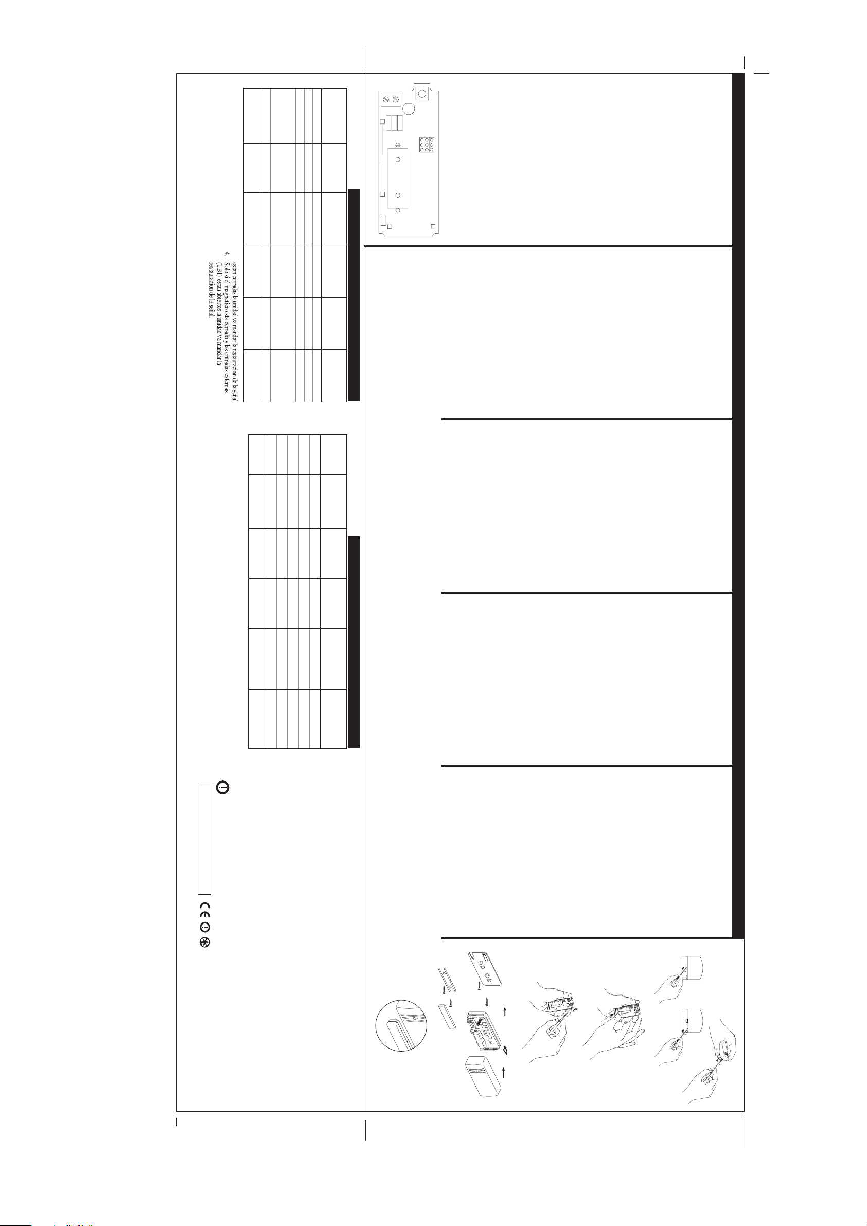
Note: the mark on the magnet's plastic case should be opposite the
S2
INPUT
(+)
B1
LED1
HOLDOFF
J1
J3
J2
S1
R11
J4
FAST
NO
+
HOLDON
SLOW
NC
BATTERY
©
ROKONET 1999
ANT1
_
ANT2
mark on the transmitter's case (fig. 5).
7.
tape.
c. Generate an Alarm signal (by momentarily opening or closing
the input terminals) and verify that the receiver has received the
signal. If the alarm signal is not detected, reposition the NOVA 71
and try again.
Note: For best results when using NOVA II, set the receiver in the
Communication Check Mode, and upon reception and verification,
return it to the Normal Mode.
FINAL MOUNTING
Separate the back part of the transmitter (fig. 3), and mount all
the parts in place (fig. 4).
If relevant, connect the sensor to the input terminals.
6.
SELECTION OF INSTALLATION LOCATION
a. Select a location best suited for communication quality
and near the intended wired detector (for switched sensor).
Place the unit at the highest possible position.
b. Temporarily attach the unit to this point using two sided adhesive
seconds. Verify that NOVA 71 has been identified by the receiver.
c. Set the receiver to Normal Mode.
Note: if for any reason it is necessary to re-send a write message,
press the tamper button for at least 3 seconds.
its coded message into the receiver's address memory. This is
accomplished by performing the following steps:
a. Set the receiver to Write Mode.
b. Remove the battery from the insulation material (fig. 2).
Send a Write message pressing the tamper button for at least 3
4.
5.
TRANSMITTER/RECEIVER COMMUNICATION SETUP
The NOVA 71 must identify itself to the system's receiver by writing
FRONT COVER REMOVAL
English
(fig. 1).
ENTRADA N.A.
SLOW/LENTO
OPEN - (OUT)
TB1 USADO
ABIERTO-
NA. (N.O.)
(FUERA)
AMBOS
(4)
CLOSED - (IN)
TB1 USADO
(PUESTO)
SOLO
TB1
TB1 USADO
(DENTRO)
SOLO
TB1
1. HOLDON bedeutet eine Todzeit von 2,5min;
2. Im Falle eines Ersch tterungsmelders, w hlen Sie die
3. Nur wenn der Magnetkontakt und der Klemmkontakt
Einstellung FAST.
RELEVANT F R
MELDUNG
HOLDOFF bedeutet keine Todzeit.
TB1
MAGNETSEN ALLEINE
ZUSTAND DES
FREE
TB1 USED
SIEHE (3)
SLOW/LENTO
CERRADO-
N.C.
CLOSED - (IN)
SLOW/LENTO
CERRADO-
NA. (N.O.)
J2 (2)
J3
J4
OPEN - (OUT)
SLOW
NO.
OPEN - (OUT)
SLOW
N.C.
MAGNETICO+
(N.O.) (TB1)
HOLDON
ENTRADA N.C.
HOLDON
(TB1)
ENTRADA N.A.
(N.O.) (TB1)
HOLDON
SCHNELLINSTALLATION:
STECKBR CKE
/KONTAKT
J1 (1)
MAGNETKONTAKT
HOLDON
ALLEINE
KLEMMANSCHLUSS
MAGNETKONTAKT
HOLDON
EINSTELLUNG DER STECKBR
MIT NC
ROKONET LIMITED WARRANTY
Rokonet Electronics, Ltd. and its subsidiaries and affiliates ("Seller") warrants its products to be free from defects in materials and workmanship under normal use for 18 months from the date of production. Because Seller does not install or connect the product and because the product may be used in conjunction with products not manufactured by the Seller, Seller can not guarantee the performance
of the security system which uses this product. Sellers obligation and liability under this warranty is expressly limited to repairing and replacing, at Sellers option, within a reasonable time after the date of delivery, any product not meeting the specifications. Seller makes no other warranty, expressed or implied, and makes no warranty of merchantability or of fitness for any particular purpose. In no
case shall seller be liable for any consequential or incidental damages for breach of this or any other warranty, expressed or implied, or upon any other basis of liability whatsoever.
Sellers obligation under this warranty shall not include any transportation charges or costs of installation or any liability for direct, indirect, or consequential damages or delay. Seller does not represent that its product may not be compromised or circumvented; that the product will prevent any persona; injury or property loss by burglary, robbery, fire or otherwise; or that the product will in all cases
provide adequate warning or protection. Buyer understands that a properly installed and maintained alarm may only reduce the risk of burglary, robbery or fire without warning, but is not insurance or a guaranty that such will not occur or that there will be no personal injury or property loss as a result.
Consequently seller shall have no liability for any personal injury, property damage or loss based on a claim that the product fails to give warning. However, if seller is held liable, whether directly or indirectly, for any loss or damage arising from under this limited warranty or otherwise, regardless of cause or origin, sellers maximum liability shall not exceed the purchase price of the product, which
shall be complete and exclusive remedy against seller.
No employee or representative of Seller is authorized to change this warranty in any way or grant any other warranty.
WARNING: This product should be tested at least once a week.
8.
7.
MONTAGGIO FINALE
Separate la parte posteriore del trasmettitore (fig.3) ed installatelo
(fig.4).Collegate il contatto ai terminali d'ingresso.
Nota: Il marchio sulla plastica del contatto magnetico deve essere
opposto al marchio del contenitore del trasmettitore (fig. 5).
8.
7.
MONTAGE FINAL
Séparez la partie arrière de l'émetteur (fig 3) et montez tous les
éléments (fig 4). Ensuite câblez le capteur aux entrées du bornier.
Note : La marque sur le contact magnétique devra être opposée à
la marque du boîtier de l'émetteur (fig 5).
il ricevitore nel modo "Controllo di Comunicazione "e dopo la
ricezione e verifica,ritornate nel modo "Normale".
71, et essayez à nouveau .
Note : Pour de meilleurs résultats quand vous utilisez NOVA II,
programmez le récepteur sur le Mode Communication et effectuez
la vérification. Ensuite retournez en Mode Normal.
c. Provocate un segnale di allarme (aprendo o chiudendo i contatti
terminali) e verificate che il ricevitore abbia ricevuto il segnale. Se
il segnale non è stato ricevuto, riposizionate il Nova 71 e riprovate.
Nota : Per un miglior risultato, quando usate un Nova II , posizionate
b. Fixez temporairement l'émetteur à l'endroit choisi avec un adhésif
double face.
c. Provoquez un signal d'alarme (en ouvrant et refermant les entrées
du bornier ) Et vérifiez que le récepteur ait bien reçu le signal. Si
le signal d'alarme n'est pas détecté, changez de place le NOVA
6.
b. Fissate temporaneamente il dispositivo con dell'adesivo doppio.
SCEGLIETE LA POSIZIONE D'INSTALLAZIONE
a. Scegliete una posizione ideale per la migliore comunicazione e
vicino al rivelatore cablato (per sensori commutati).
Installate il dispositivo il più in alto possibile.
6.
CHOIX†DU MEILLEUR ENDROIT POUR FIXER LE
NOVA 71
a. Choisissez le meilleur endroit pour une communication optimale,
près du détecteur filaire (pour les capteurs). Installez le NOVA 71
le plus haut possible.
pendant au moins 3 secondes.
premete il tamper per circa 3 secondi.
en suivant les instructions ci-après :
a. Programmez le récepteur en Mode Adrossage (write)
NOVA 71 ait bien été identifié par le récepteur.
b. Au niveau du NOVA 71, retirez la pile du matériel d'isolation
(fig 2). Appuyez sur l'autoprotection du NOVA 71 pendant au moins
3 secondes pour envoyer un message adressage. Vérifiez que le
c. Programmez le récepteur en Mode Normal.
Note : Si pour quelque raison, il est nécessaire d'émettre à nouveau
un message adressage, appuyez sur l'autoprotection du NOVA 71
RIMUOVETE IL COPERCHIO FRONTALE
(fig. 1).
4.
5.
Français
ADRESSAGE DU NOVA 71 AU RECEPTEUR
Le NOVA 71 doit se faire reconnaître du récepteur en inscrivant son
code dans la mémoire d'adresses de celui-ci. Cette étape se réalise
RETIEZ LE COUVERCLE
(Fig 1)
4.
5.
Italiano
IDENTIFICAZIONE DELL NOVA 71 AL RICEVITORE
Il Nova 71 deve identificarsi al suo ricevitore scrivendo il suo
messaggio di codice che deve essere registrato nella memoria del
ricevitore. Ciò si ottiene :
a. Disponete il ricevitore nel modo " Write"
b. Rimuovete la batteria del materiale isolante (fig 2)
Premete il tamper per circa 3 secondi per inviare un messaggio
"Write". Verificate che il Nova 71 sia stato identificato dal ricevitore.
c. Disponete il ricevitore nel modo "Normale"
Nota: Se in caso fosse necessario rinviare un messaggio "Write",
KLEMMANSCHLUSS
OPEN - (OUT)
TB1 USED
4. Nur wenn der Magnetkontakt geschlossen und der
Klemmkontakt offen ist, sendet das Ger t eine
Klarmeldung an den Empf nger.
FCC ID:
CONSULT WITH YOUR LOCAL RADIO AGENCY ABOUT
THE POSSIBILITY OF OPERATION OF THIS DEVIC.
SIEHE (4)
geschlossen ist, sendet das Ger t eine Klarmeldung an
den Empf nger.
KLEMMKONTAKTS ALLEINE
TB1 USED
ZUSTAND DES
KLEMMKONTAKTS ALLEINE
TB1 USED
ZUSTAND DES
(3) Consult the dealer or an experienced radio/TV technician for help.
Changes or modifications to this equipment not expressly approved by the
party responsible for compliance, Rokonet Electronics Ltd. could void the
user’s authority to operate the equipment.
SLOW
NO.
CLOSED - (IN)
SLOW
N.C.
CLOSED - (IN)
SLOW
NO.
this equipment does cause harmful interference to radio or television reception, which can be determined by
turning the equipment off and on, the user is encouraged to try to correct the interference by one or more of
the following measures:
(1) Reorient or relocate the receiving antenna.
(2) Increase the separation between the equipment and receiver.
MAGNETKONTAKT
HOLDON
MIT NO
KLEMMANSCHLUSS
NC
HOLDON
ALLEINE
KLEMMANSCHLUSS
NO
HOLDON
communications. However, there is no guarantee that interference will not occur in particular installation. If
üCKEN
ALLEINE
NOTE: This equipment has been tested and found to comply with the limits for a Class B digital device, pursuant
to part 15 of the FCC Rules. These limits are designed to provide reasonable protection against harmful
interference in a residential installation. This equipment generates, uses and can radiate radio frequency energy
and, if not installed and used in accordance with the instructions, may cause harmful interference to radio
JE4WT7IV2
8.
7.
MONTAJE FINAL
Separar la parte trasera del transmisor (Fig 3), y montar todas las
partes en sus respectivos lugares (Fig 4).
Si es necesario, conectar el sensor a los terminales de entrada.
frente a la marca en la caja del transmisor.
Atención: la marca en la caja pilástica del magneto debe colocarse
8.
Hinweis: Die gekennzeichnete-Stelle des Magnetkontakts muß
immer neben der gekennzeichnete-Stelle des Sende-Moduls
positioniert werden (Fig.5).
7.
ENDGÜLTIGE MONTAGE
Trennen Sie das Gehüuse-Rückteil (Fig.3) und montieren Sie das
Rückteil an seiner†endgültige Position (Fig.4).
Falls erwünscht, verbinden Sie die Externe-Sensoren mit den
Eingangsklemmen.
Hinweis: Für den besten Erfolg, bei Verwendung des NOVA-
Empfänqers, setzen Sie den†Empfänger auf Communication -
Check - Modus und abhängig vom Empfang und von der Erkennung
kehren Sie dann in den Normalmodus zurück.
reubicar el NOVA 71 e intentar nuevamente.
Nota: Para obtener los mejores resultados al usar un NOVA II,
colocar el receptor en Modo de Verificación de Comunicación, y
luego retornarlo al Modo Normal.
Schließen der†Eingangsklemme) und stellen Sie sicher, daß der
Empfänger das Signal empfangen hat. Falls das Alarmsignal nicht
detektiert wird, wechseln Sie den Montageort†des NOVA 71 und
versuchen Sie es erneut.
b. Fijar temporariamente la unidad utilizando cinta adhesiva de
doble cara.
c. Generar una señal de Alarma (abriendo o cerrando
momentáneamente los terminales de entrada) y verificar que el
receptor ha recibido la señal. Si la señal de alarma no es detectada,
höchstmöglichen Stelle.
b. Montieren Sie das Gerät provisorisch mit Hilfe eines doppelseitigen
Klebebandes†an dieser Stelle.
c. Aktivieren Sie ein Alarmsignal (durch kurzzeitiges Öffnen und
6.
WRITE, pulsar el botón tamper al menos 3 segundos.
de comunicacón y cerca del detector alambrado propuesto (para
SELECCION DE†LA†UBICACION DE INSTALACION
a. Seleccionar una ubicación adecuada para conseguir alta calidad
sensor exterior). Colocar la unidad a la máxima altura posible.
TRANSMISOR/RECEPTOR
El NOVA 71 debe identificarse ante el receptor del sistema
"escribiendo" su menasaje codificado en la memoria de dirección
del receptor. Esto es llevado a cabo de la siguiente manera:
a. Colocar el receptor en Modo WRITE.
b. Remover la batería del material aislante. Un mensaje WRITE
será enviado pulsando el botón tamper al menos 3 segundos.
Verificar que el NOVA 71 ha sido identificado por el receptor.
c. Colocar el receptor en Modo NORMAL.
Nota: si por alguna razón es necesario re-transmitir un mensaje
6.
Nachricht in den Adressenspeicher des Systemempfängers selbst
Der NOVA 71 muß sich durch die Übertragung einer codierten
identifizieren. Dies wird durch die†Ausführung folgender Schritte
erreicht:
a. Folgen Sie den Anweisungen zum Adressmodus in der
min. 3 Sek.†den Deckelkontakt des Melders gedrückt .
AUSWAHL DES MONTAGEORTES
a. Wählen Sie eine Stelle die am besten für eine einwandfreie
Übertragung geeignet ist†und nahe am anzuschließenden
verdrahteten Detektor liegt. Montieren Sie das Gerät†an der
c. Setzen Sie den Empfänger auf Normalmodus.
Hinweis: Falls das Einlernen wiederholt werden muß, halten Sie für
Betriebsanweisung des†Empfängers.
b. Verbinden Sie die Batterie mit der Batterieanschlußklemme
(Fig 2). Während der Bestromungsphase wird eine Adressmeldung
gesandt nachdem der Deckelkentakt des Melders min. 3 Sek.
eingedrücht gehalten wird.
4.
5.
ESTABLECIENDO LA COMUNICACION
ABRIR LA CUBIERTA
Español
(Figura 1).
4.
5.
Deutsch
KOMMUNIKATIONSEINSTELLUNG
ABNEHMEN DES GEHÄUSEDECKELS
fig. 5
fig. 4
(fig.1)
a b
©
R
O
K
O
NE
T
1
9
9
8
©
ROKONET 1998
fig. 3
fig. 2
fig. 1
 Loading...