

Risco Wireless WatchOUT PIR 868, RWT312PR800A, RWT312PR400A, Wireless WatchOUT PIR 433 Installation Instructions Manual
Portuguese Français Español Italiano
English
Wireless PIR Outdoor Detector
Rivelatore PIR da esterno via radio
Detector Inalámbrico de Exterior PIR
Détecteur PIR extérieur sans fil
Detector Infravermelho Passivo Externo Sem Fio
Installation Instructions
Istruzioni per l’installazione
Instrucciones de Instalación
Manuel d'installation
Instruções para Instalação
2 Installation Instructions

Installation Instructions 3
English
Table of Contents
Installation ...................................................................................................................4
Introduction..................................................................................................................4
Mounting .....................................................................................................................4
Mounting Considerations.........................................................................................................4
Wall Mount Installation ............................................................................................................6
Flat Mounting:..........................................................................................................................6
45° angle Mounting (Left side mounting) ................................................................................6
Changing Back Tamper position .............................................................................................7
Back Tamper Terminal Wiring ......................................................................................7
DIP Switch Settings .......................................................................................................7
Walk test..................................................................................................................................8
LEDs Display ................................................................................................................8
Operational Modes: .....................................................................................................8
Transmitter/Receiver Communication link setup: ..........................................................8
High / Low power Jumper ............................................................................................9
Standard Swivel Installation .........................................................................................9
Wall Mounting..........................................................................................................................9
Replacing Lenses ........................................................................................................11
Lens Types..................................................................................................................12
Technical Specification................................................................................................13
Ordering Information .................................................................................................13
Accessories Kits ..........................................................................................................13
4 Installation Instructions
Installation
Introduction
RISCO Group's wireless PIR outdoor detector, Wireless WatchOUT, is a unique detector with signal
processing based on two Passive Infrared (PIR) correlated channels. The detector can
communicate with RISCO Group's ProSYS control panel or other RISCO Group's wireless
receivers.
The following instructions describe the installation of the Wireless WatchOUT. For detailed
information regarding installation, refer to the relevant receiver installation instructions.
Mounting
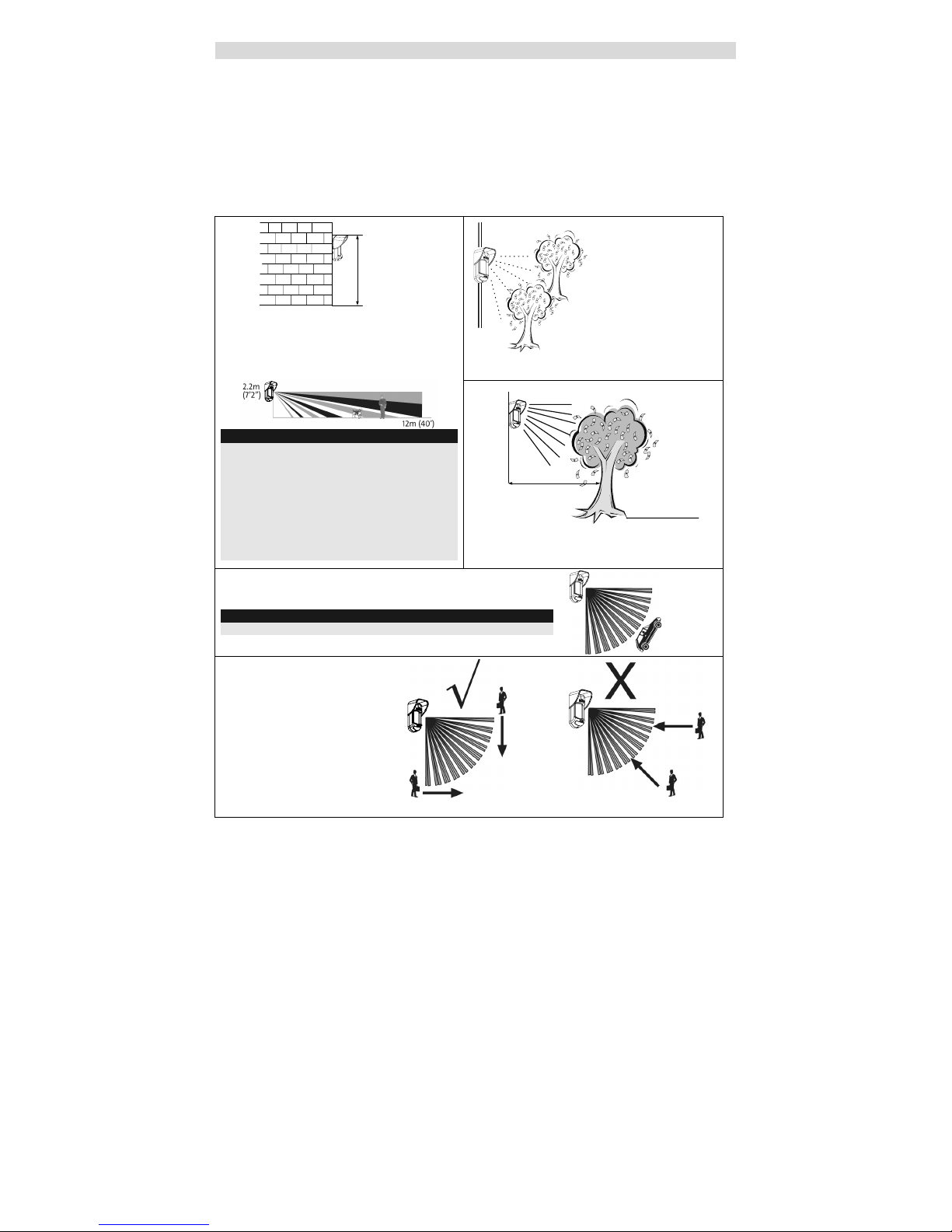
Mounting Considerations
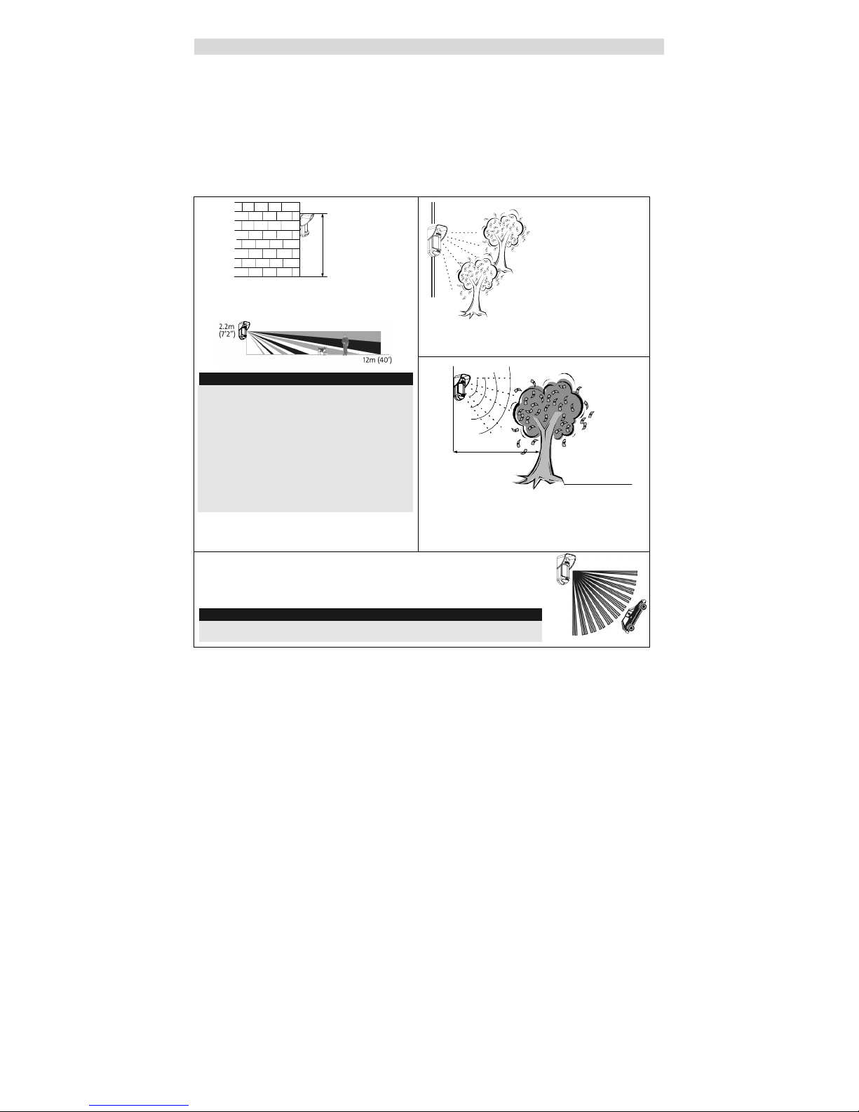
If possible, avoid pointing the detector to
moving objects (swaying trees, bushes etc.)
1m - 2.7m
(3'3" - 8'9")
Optional Height: 1m – 2.7m
(3'3"-8'9")
Typical Height: 2.2m (7'2")
Default Lens: Wide angle 12m (40') 90°
(RL300)
Note:
1. For low installations, below 1.7m (5'6") in which
pet immunity is required, use the supplied
RL300F lens (Low wall or fence installations).
2. The detector's pet immunity (height of an animal,
no weight limitation), is up to 70 cm (2'4"), when
installing the detector at 2.2m (7'2"). If the
installation is below the height mentioned above,
the Pet Immunity decreases accordingly; every
10 cm (4") decrease in installation height leads
to 10 cm (4") decrease in pet height immunity.
Out of
Detection Range
With moving objects
keep distance of
minimum 5 meters (16')
5m (16')
Ensure any objects do not obstruct the field of
view. Pay attention to growing trees or bushes,
plants with big moving leaves etc.
For installations with extensive vehicle traffic or targets beyond
the required detection range, it is recommended to tilt the
detector down.
Note:
Tilting the detector down may reduce the pet immunity
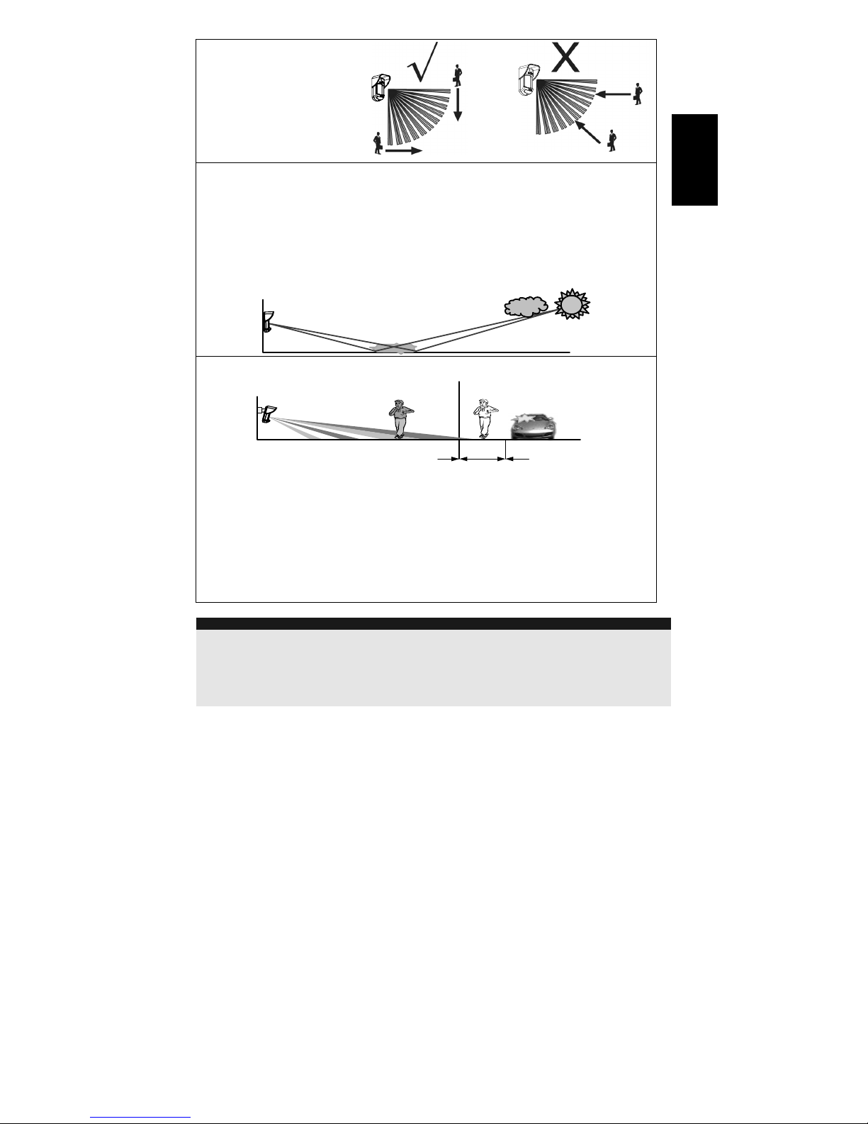
For optimum detection, select a
location that is likely to
intercept an intruder moving
across the coverage pattern at
a 45° trajectory.
Installation Instructions 5
English
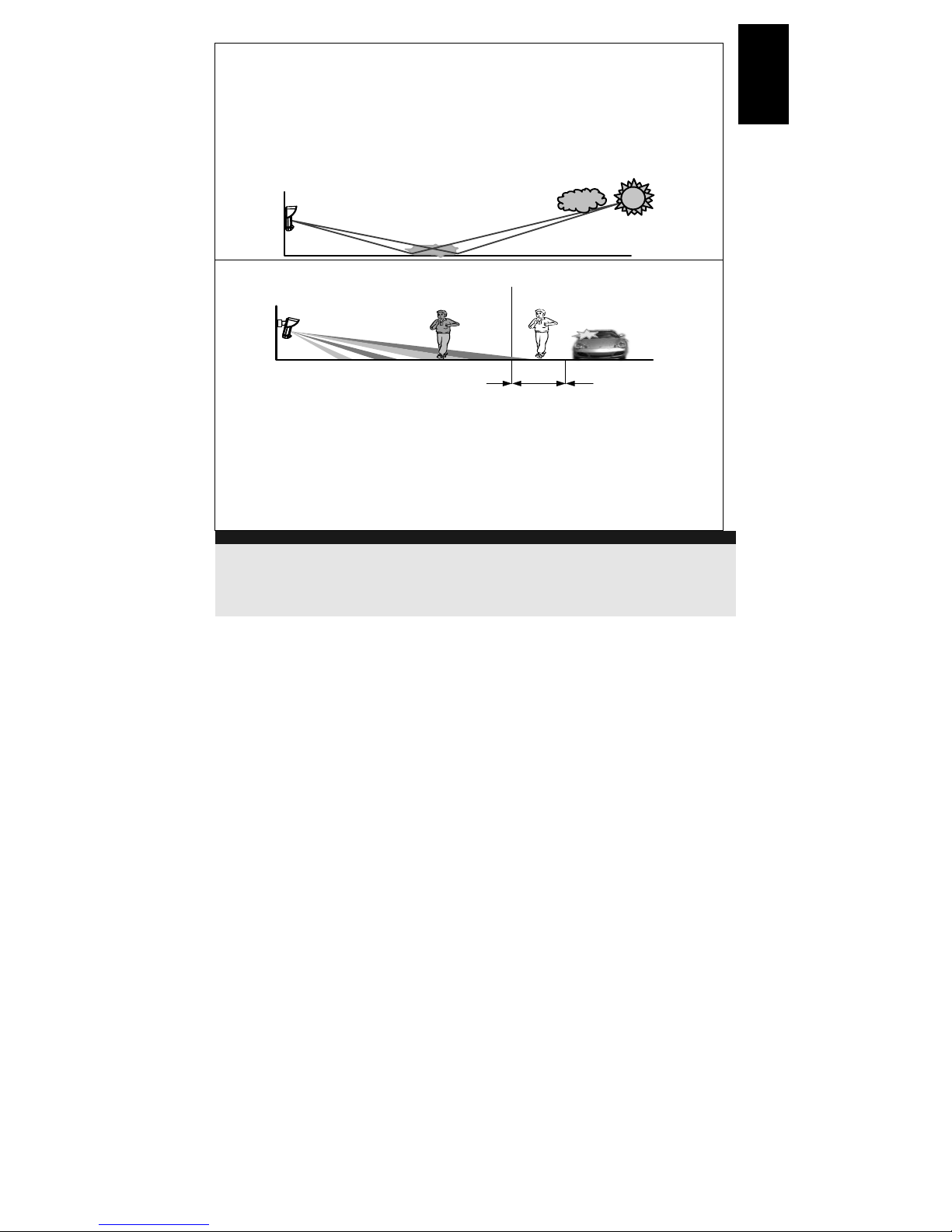
Installing Wireless WatchOUT PIR in challenging situations:
In the following situations, rapid and significant infrared radiation changes can happen in both
PIR channels together, resulting in false alarms and therefore care should be taken.
1. Situations in which metal and/or glass objects measuring over 70cm (2’4”) in height from the
ground are in the field of view of the detector (cars, metal gates, shutters, metal walls,
windows, etc.)
2. Situations in which a reflective surface on the ground larger than 1m (3’4”) in diameter may
cause reflection into the detector’s lens. Examples of a reflective surface on the ground are
a puddle, wet road or car park, smooth concrete or asphalt surface, swimming pool, etc.
Water Re flection
To avoid false alarms in the above situations:
Area 1
Area 2
1m
12m
(40')
Reduce the detection range to 1m less than the distance of the metal/glass object or possible
ground surface reflection, as follows:
1. Install the Wireless WatchOUT PIR on the supplied standard swivel bracket.
2. Reduce the detection range by sliding up the Wireless WatchOUT PCB within the detector
housing, and by tilting the detector down on the swivel bracket.
3. To reduce the required tilting angle, it is recommended to install the detector at a lower
mounting height and to use the Pet immune lens for low installations.
4. Confirm by walk-test that the Wireless WatchOUT PIR detects in Area 1, and that no
detection occurs when walking in Area 2.
NOTES:
1. Please note that any outdoor PIR detector will require reduction in range to a shorter distance than the car,
metal object or surface reflection (so that these objects won’t be protected) in order to eliminate false alarms.
2. For full 15m (50’) coverage in the above situations, it is highly recommended to install the wired
WatchOUT DT, the only outdoor detector with 2 PIR channels and 2 Microwave channels.
3. Wireless WatchOUT detectors include high quality Silicon filters on the PIR sensors for blocking out white light
interferences. These filters are not intended to block infrared thermal radiation.
6 Installation Instructions
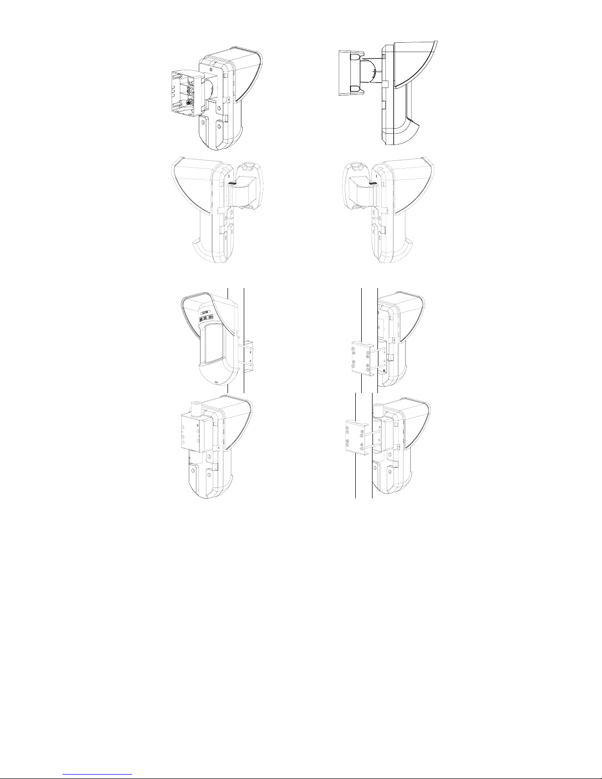
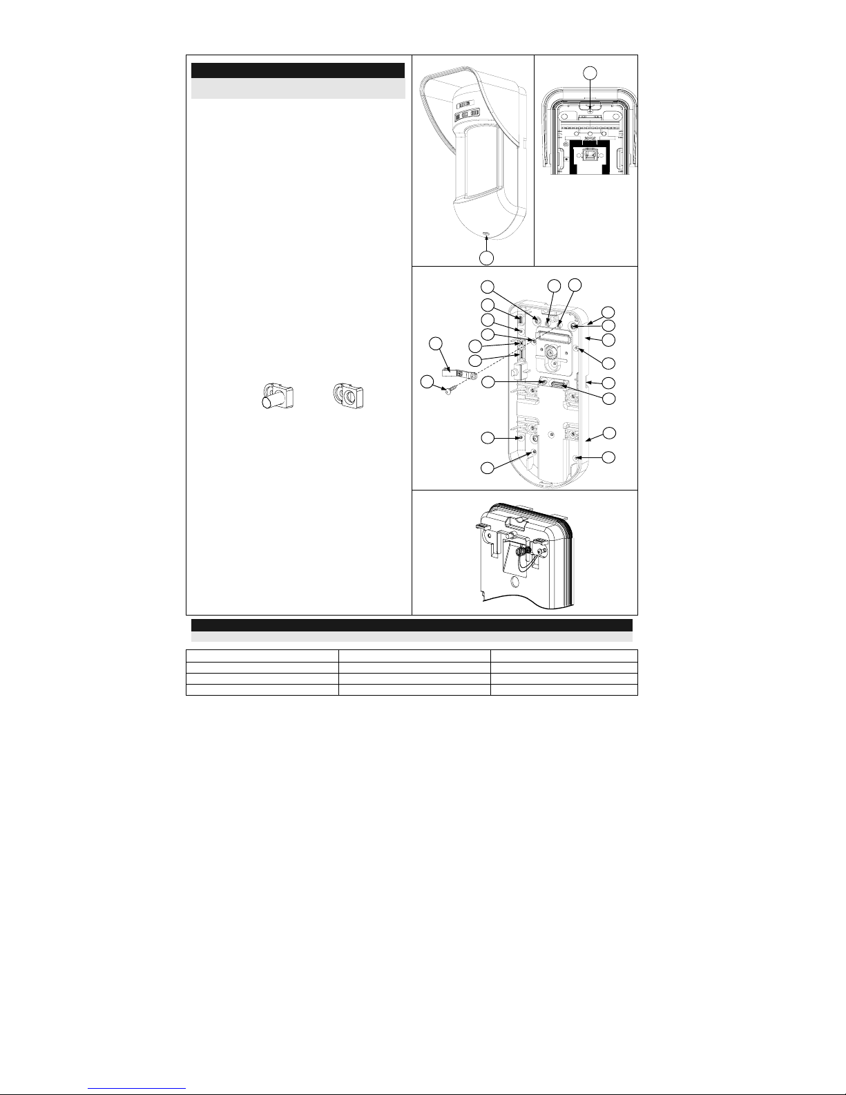
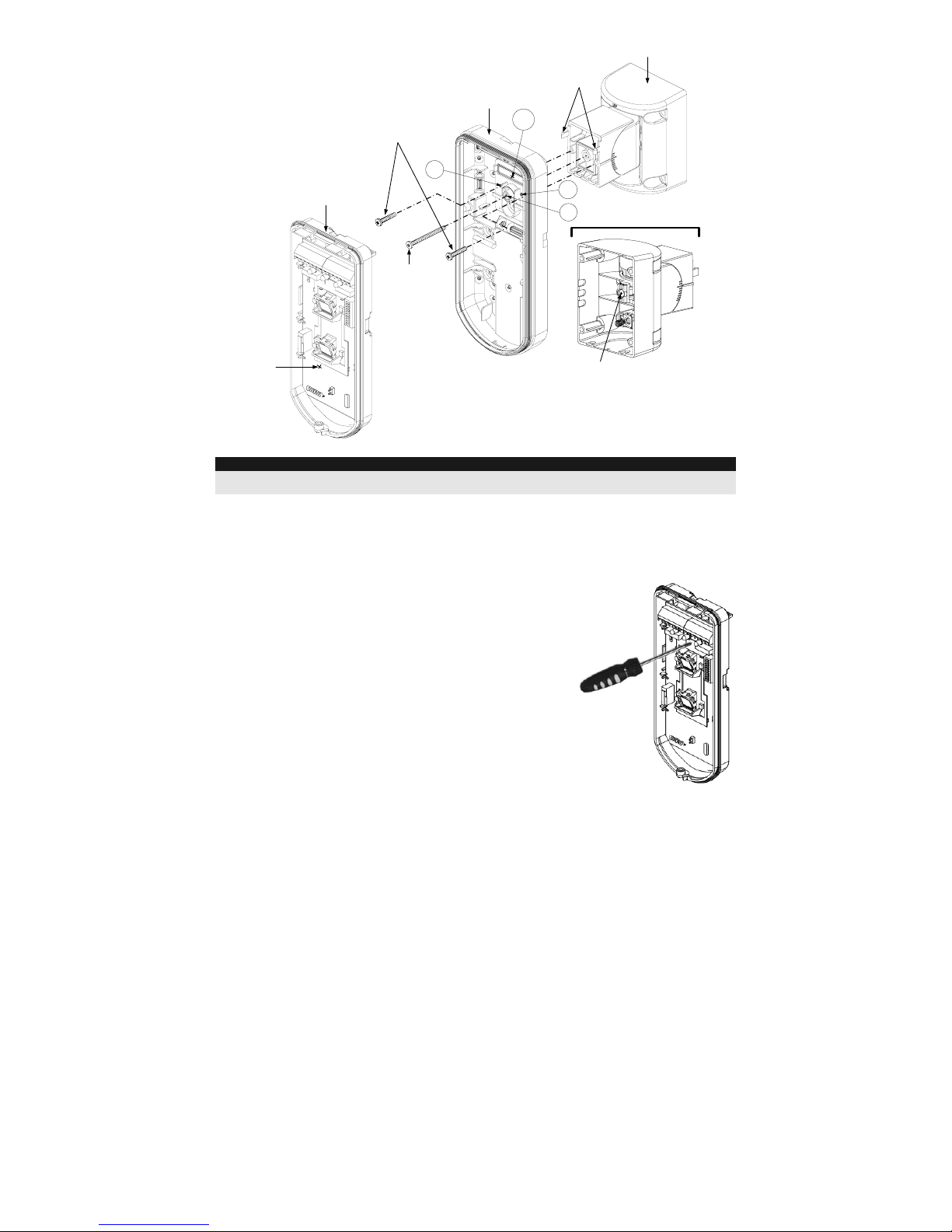
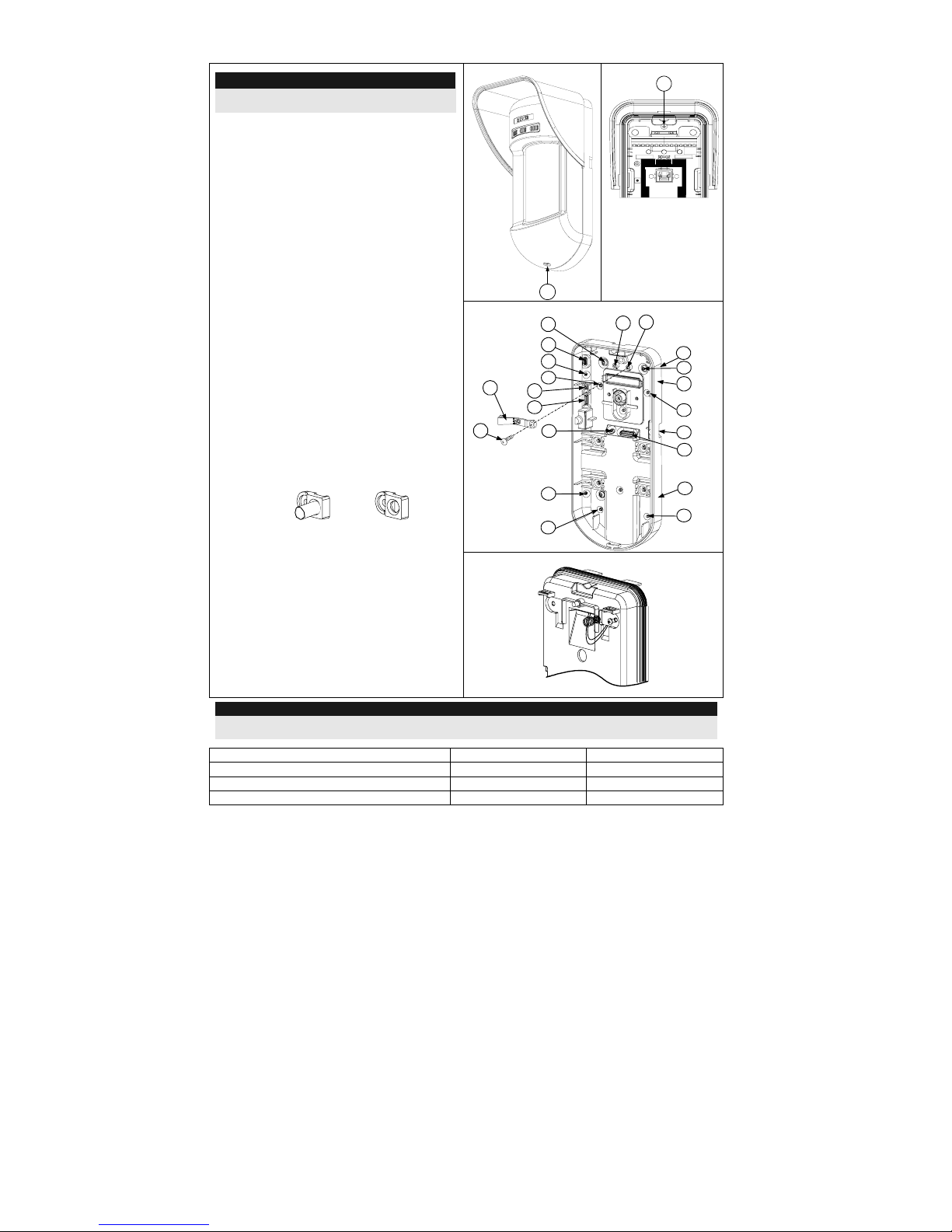
Wall Mount Installation
Figure 1
C1
Figure 2
I1
Figure 3
Tamper
Lever
A
T5
T1
B2
W9
B3
W2
B
L1
T3
B1
L2
W3
B4
R1
R2
(not visible)
T2
T6
(not visible)
T4
W5
W6
Note:
The installation knockouts numbering are marked
on the back plate.
1. Open Wireless WatchOUT front cover
(unlock C1, Figure 1).
2. Release internal base (unlock I1, Figure
2).
3. Select mounting installation as follows:
Flat Mounting:
Open knockouts on external base (Figure 3).
• B1 - B4: Wall mounting knockouts
• T1: Back tamper knockout
45° angle Mounting (Left side
mounting):
a. Open knockouts on external base
(Figure 3).
• L1, L2: Left mounting knockouts
• T3: Left tamper knockout
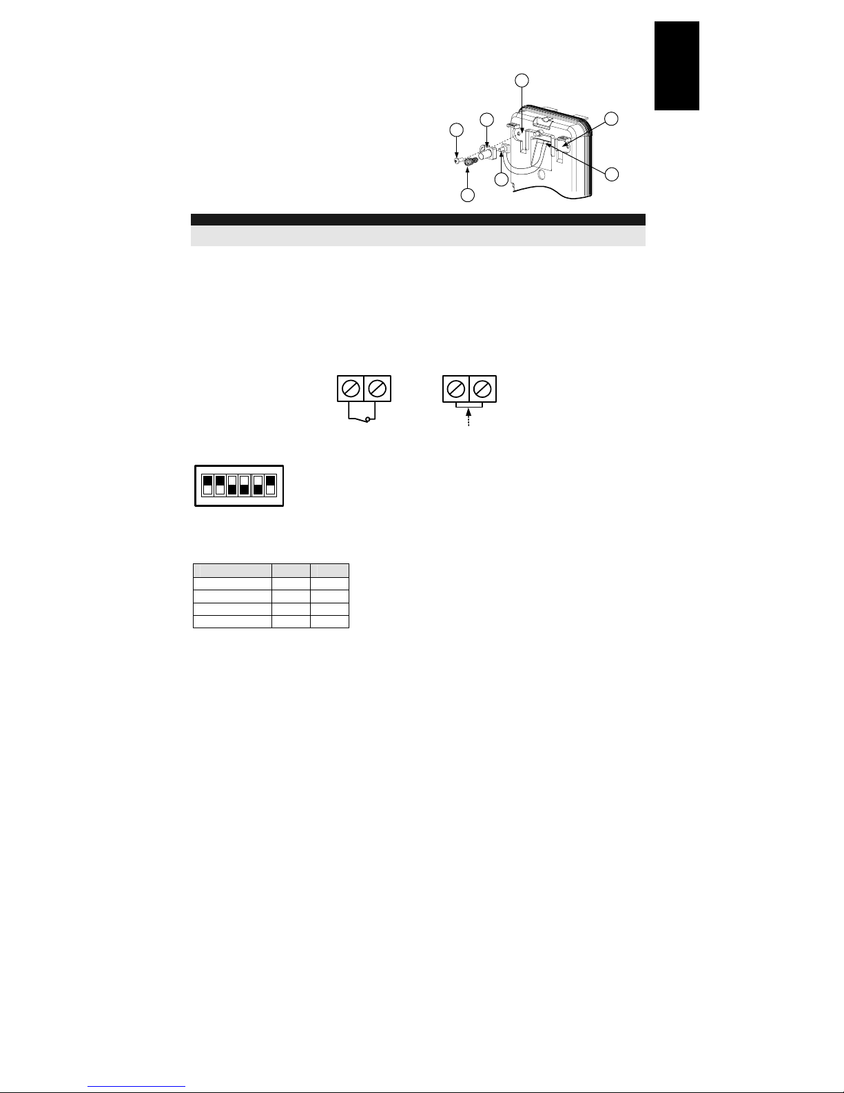
b. Remove tamper spring (Figure 4).
c. Replace tamper bracket (Item 1) with
supplied flat tamper bracket (Item 2).
Item 1
Item 2
d. Insert Tamper lever B onto T6 and T3
and secure screw A (Figure 3).
4. Secure external base to the wall.
5. Insert tamper wires through internal base
(Figure 4).
6. Secure internal base to external base (lock
I1, Figure 2).
7. Close the front cover (Lock C1, Figure 1)
after wiring and setting DIP switches.
8. Walktest the detector.
Figure 4
Note:
For 45° right side installation use the equivalent units on the external base as follows:
Knockouts Description Left Right
Mounting Knockouts L1, L2 R1, R2
Tamper spring knockouts T1,T3 T2,T4
Tamper screw anchor T5 T6
Installation Instructions 7
English
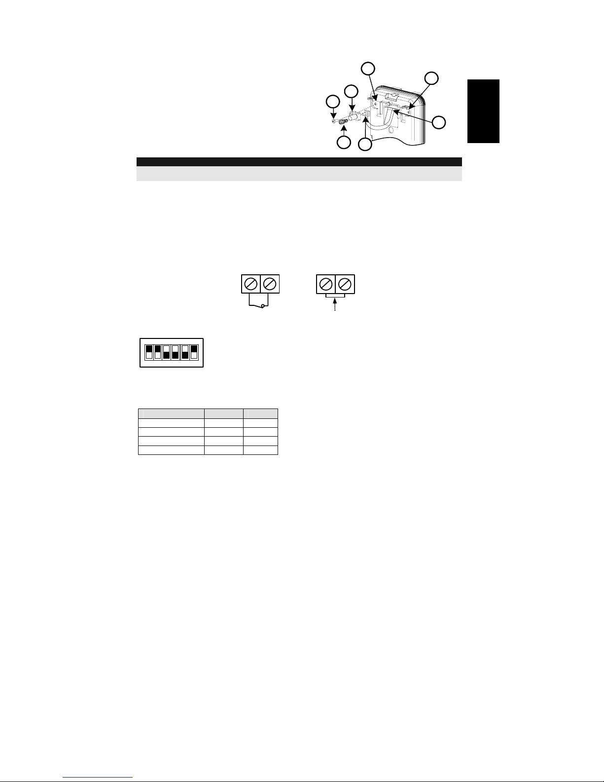
Changing Back Tamper position
The back tamper is by default secured on the right
side of the internal base (Rear view). If you wish to
move it to the left side (rear view), do the following
(Figure 5):
1. Remove tamper screw 1 in order to release the
tamper from position 7.
2. Ensure tamper spring (2) rests over tamper wire
base 4.
3. Ensure plastic tamper bracket (3) rests over
both 2 and 4.
4. Secure tamper screw (1) into (3) over position 6.
Figure 5
Left Side
Tamper
Right Side
Tamper
3
6
1
2
4
7
5
Figure 5
Notes:
1. Verify that you hear a "Click" when attaching the tamper spring to the wall.
2. For pole installation, the tamper can be moved to the bottom right-hand side of the internal base.
Back Tamper Terminal Wiring
If you wish to use the back tamper (recommended) remove the short from the back tamper terminal
block and connect the back tamper wires to the back tamper terminal block.
Back Tamper in use
BACK TAMPER
Back Tamper not used
Short
H1 H1
DIP Switch Settings
123456
ON
Factory
Default
DIP 1: LEDs operation
On: LEDs enabled
Off: LEDs disabled
DIP 2-3: PIR Detection Sensitivity
Sensitivity DIP2 DIP3
Low Off Off
Mid Off On
Normal On Off
Maximum On On
DIP 4: Supervision time
On: 65 minutes
Off: 15 minutes
DIP 5: Normal/Test modes
On: Test
Off: Normal
DIP 6: Anti masking operation
On: Enabled
Off: Disabled
8 Installation Instructions
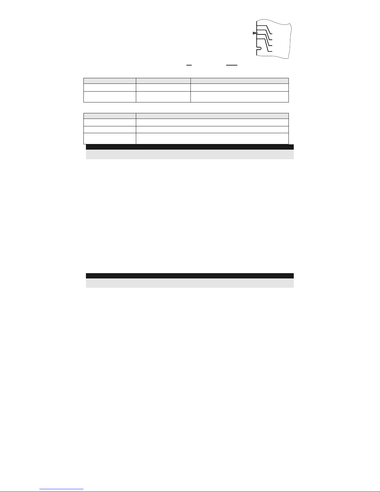
Walk test
Two minutes after applying power, walk test the protected area to verify
proper operation.
For installations on uneven surfaces slide the PCB inside the internal base to
the appropriate setting according to the desired height (1.0m, 1.5m, 2.2m,
2.7m) as printed on the bottom left corner of the PCB or use the standard
swivel accessory.
For reducing the detection range, slide the PCB up
or tilt the swivel down.
1.50M
2.20M
2.70M
1.00M
PCB
LEDs Display
LED State Description
RED
Steady Indicates ALARM
RED & YELLOW
RED followed By
YELLOW
Indicates ALARM + Anti-masking
Operational Modes:
Operational Mode Description
Normal
Dead time (between detection alarms) is 2.5 Minutes.
Test (walk test)
Dead time (between detection alarms) is 2.5 sec.
Write
The unit transmits a WRITE message each time both of the Tamper
Switches (back and cover) are closed for at least 3 seconds.
Notes:
After power up the detector enters into test mode for a period of 20 minutes (disregarding the DIP switch Modes
Position).
Transmitter/Receiver Communication link setup
The detector must identify itself to the system’s receiver by writing its coded message into the
receiver’s address memory. This is accomplished by performing the following steps:
1. Set the receiver to Write Mode.
2. Remove the insulation material from the batteries and place them in the batteris holders on
the PCB on the right direction (pay attention to the "+" and "–" diagram on the PCB)
3. Send a WRITE message by pressing both of the tamper switches (back and cover) for at
least 3 seconds.
4. Verify that the detector has been identified by the receiver.
CAUTION NOTICE
Changes or modifications not expressly approved by RISCO Group may void the user’s authority to
operate this equipment.
Simultaneous transmissions from two different units may cause message interference resulting in
loss of information.
The communication quality of this unit may be affected by its surrounding environment. Nearby
electrical equipment may interfere with its normal operation.
The operation of this unit must, therefore, be tested at each installation since its transmission
quality may vary as a result of operational conditions.
NOTE:
DIP-Switch 1 should be in ON position to enable LED indications (regardless during the first 20 minutes after
power up).
Installation Instructions 9
English
High / Low power Jumper
The jumper on selector J8 needs to be on OFF (High Power
position) unless sold in countries with FCC compliance.
Low
Power
High
power
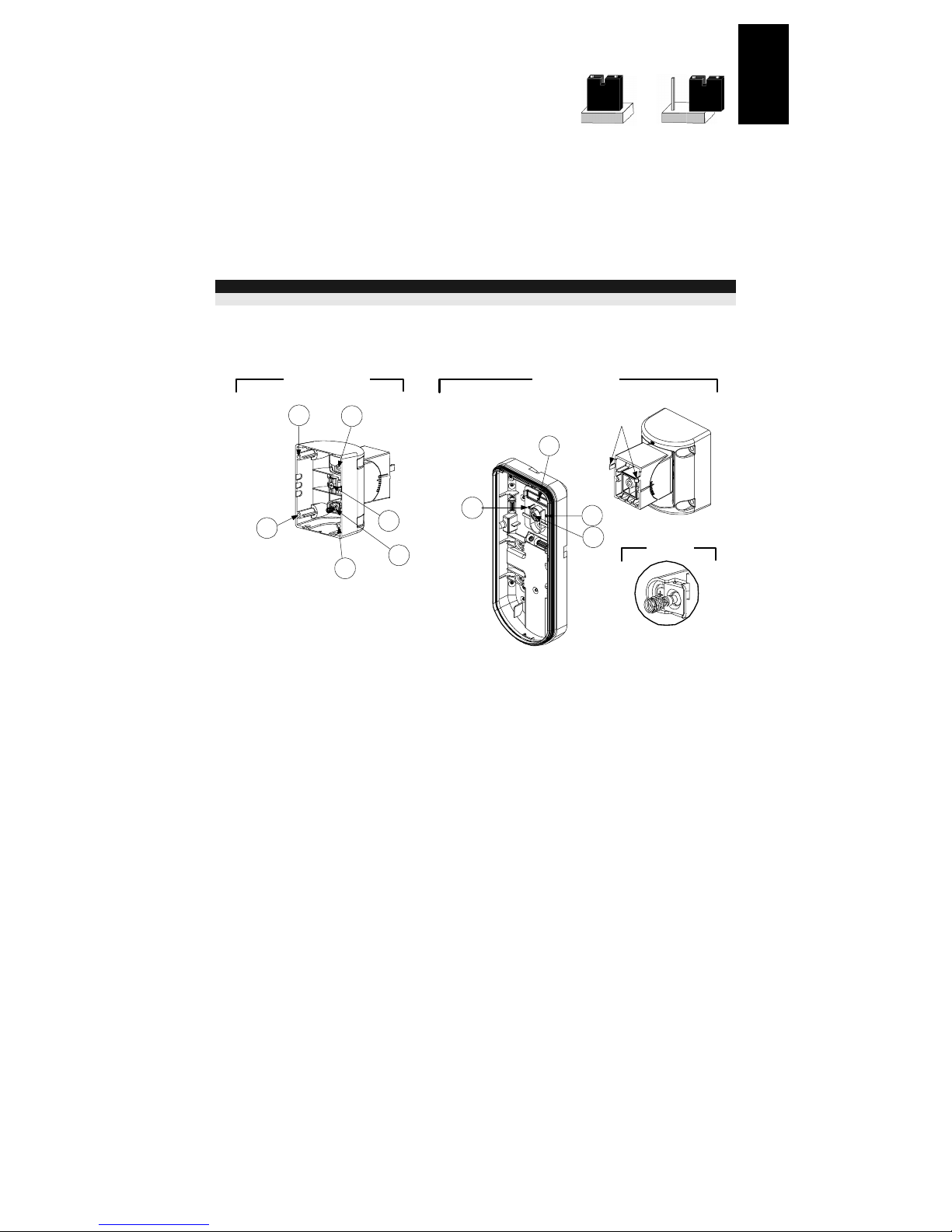
Standard Swivel Installation
The Outdoor detector packaging contains a standard swivel for flexible installation. Please follow
the instructions below for mounting the detector with the Standard Swivel:
1. Open Wireless WatchOUT front cover (Unlock C1, Figure 1).
2. Release internal base (Unlock I1, Figure 2).
3. Remove back tamper from the internal base (see the “Changing Back Tamper Position"
paragraph on page 7) and connect it to S5 (Figure 6, Detail A) on the Standard Swivel.
4. Select the mounting installation as follows:
Note:
Ensure that you see the engraved UP mark on the upper front face of the swivel.
Wall Mounting:
1. Insert back tamper wires through the Swivel Wires Passage (Figure 6, Detail B).
2. Secure swivel to the wall through holes S1, S3, S6 and S8.
Detail B
S1
W1
S2
S3
Snaps
Detail C
S1
S2
S8
S6
S5
S4
Tamper
(see Detail C)
Detail A
Standard Swivel
Figure 6
3. Connect the external base to the swivel using the dedicated snaps (Figure 8).
10 Installation Instructions
External Base
Angle Locking
Screw
(See Note 2)
See Detail A
Swivel to External Base
Connecting Screws
Detail A
Swivel Assy
Connecting Screw
(See Note)
Snaps
S1
W1
S2
S3
PCB
Internal Base
Figure 7
NOTE:
Do not open or close the Swivel Assy Screw since it is used for connecting the swivel parts only
(factory tightened).
4. Secure external base to swivel with two screws fastened trough knockouts S1 and S2
(Figure 7).
5. Insert the supplied angle locking screw from the external base through the angle locking screw
knockout S3 on the external base to the standard swivel (Figure 7).
6. Tilt and Rotate the Standard Swivel to the desired position.
Once the Standard Swivel is in the desired position, secure
the angle locking screw.
7. Line up the internal base onto the external base. Insert
tamper wiring through the internal base.
8. Secure internal base to external base (Lock I1, Figure 2).
9. To readjust the Standard Swivel when the PCB is installed
(Figure 8):
a. Bend down the black foam located below the RED LED on
the PCB (enough to reach the Swivel locking screw).
b. Use a Hex screwdriver to release the locking screw (see
Figure 8).
c. Tilt and/or Rotate the Standard Swivel to the desired
position.
d. Secure the angle locking screw.
Figure 8: PCB
Installation Instructions 11
English
NOTE:
When marks on the two movable parts are aligned (Figure 7), the Standard Swivel is in 0° vertical /horizontal
position. Each click from this position represents shifting of 5° in vertical / horizontal position.
10. Close the front cover (Lock C1, Figure 1) and walk test the detector.
NOTE:
The screw has to pass through External Base and locked to the swivel.
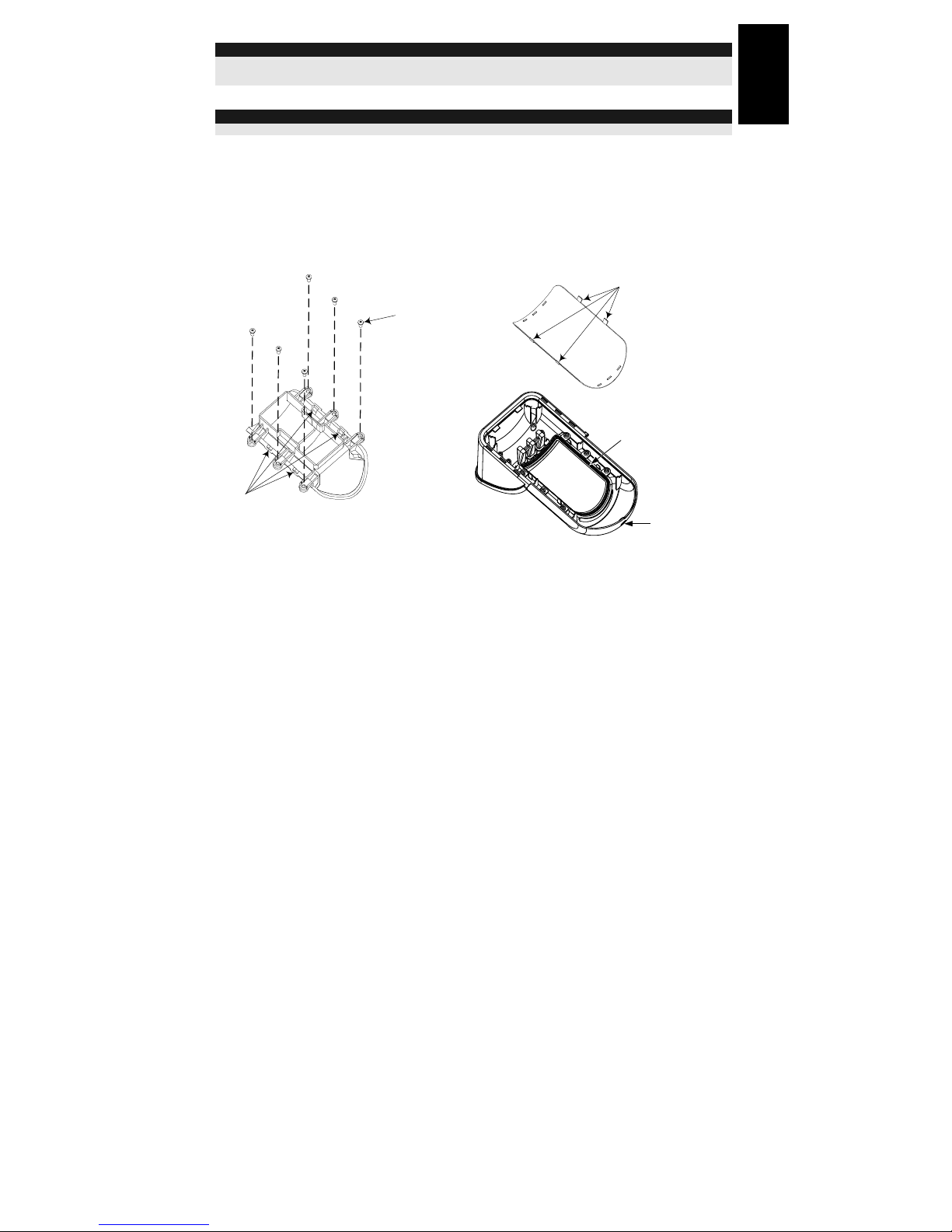
Replacing Lenses
1. Unlock the six screws that hold the lens holding sleeve from the back of the front cover.
2. To release the protective sleeve, gently push the lens from the external side of the front cover.
3. Disconnect the lens from the sleeve by gently pushing the lens clips that secure it to the sleeve.
4. Replace the lens. Place the 4 clips of the lens into the matching holes on the sleeve.
5. Insert the protective sleeve back into place on the front cover. Pay attention to place the sleeve
over the sealing rubber.
6. Secure the 6 holding screws back to their place.
Lens Protect ing
Sleeve
Sockets for
Lens Clips
Sleeve Locking
Screws
.
Lens Locking
Clips
Sealing Rubber
Front Cover
Locking Screw
Figure 9
12 Installation Instructions
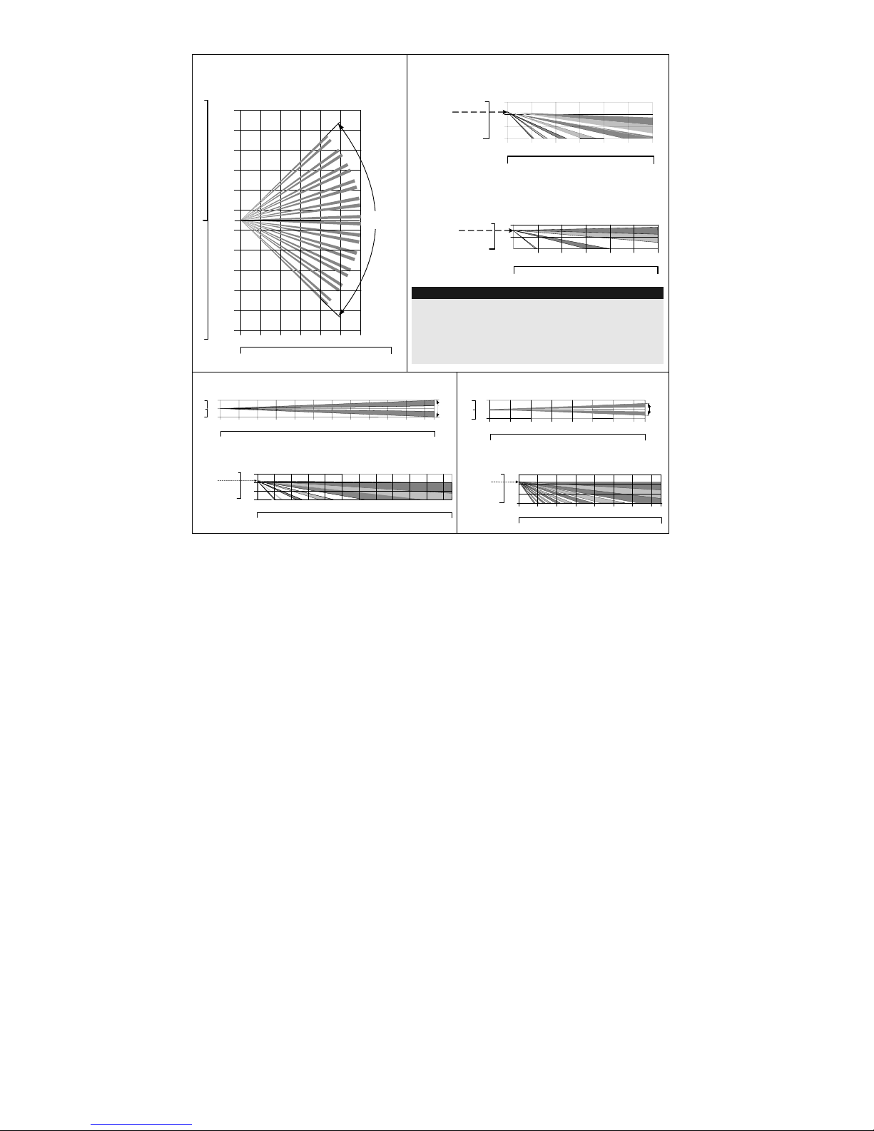
Lens Types
Wide angle lens (RL300) /
Low installation Pet lens (RL300F) :
Top view
11
11
0
0
10
20
30 40 50
10
20
30
40
10
20
30
40
2468100121415
1
3
5
7
9
0
1
3
5
7
9
90°
Wide angle lens (RL300):
Side View
Typical
Installation
Height:
2.2m (7'2")
0
10
246810012
0
10
20
30 40
1
3
0
Feet
Meters
Feet
Low installation - Pet lens (RL300F) :
Side view
Typical
Installation
Height:
1.5m (5'3")
Feet
0
6
246810012
0
10
20
30 40
1
0
2
Meters
Feet
Note:
The detector's Pet Immunity (height of an animal, no weight
limitation), is up to 70 cm (2'4"), when installing the
detector at 2.2m (7'2"). If the installation is bellow the
height mentioned above, the Pet Immunity decreases
accordingly; every 10 cm (4") decrease in installation
height leads to 10 cm (4") decrease in pet height immunity.
Long range lens (RL300LR): Top view
2468100 12141618202223
0
10
20
30 40 50
60 70 75
1
0
1
0
3
3
Feet
Meters
Feet
5°
Barrier lens (RL300B): Top view
2468100121415
0
10
20
30 40 50
1
0
1
0
3
3
Feet
Meters
Feet
5°
Long range lens (RL300LR): Side view
0
10
1
3
0
246810012141618202223
Meters
0
10
20
30 40 50
60 70 75
Feet
Typical
Installation
Height:
2.2m (7'2")
Barrier lens (RL300B): Side view
2468100121415
0
10
20
30 40 50
Feet
Meters
0
10
1
3
0
Typical
Installation
Height:
2.2m (7'2")
Feet
Installation Instructions 13
English
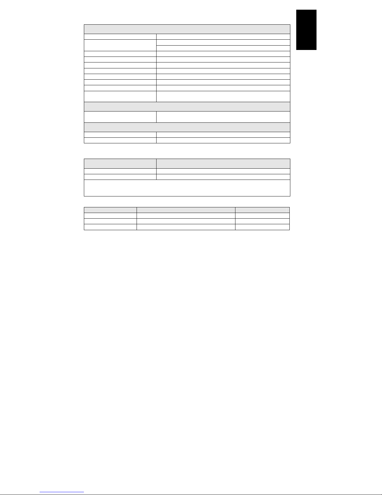
Technical Specification
Electrical
Current consumption (standby) 35uA at 3 VDC (average)
43mA at 3 VDC (Max. with LED OFF) Current consumption (Alarm
transmission)
53mA at 3 VDC (Max. with LED ON)
Dead time (Normal Mode) 2.5 minutes
Modulation type ASK
Battery life 3 years (Normal Mode)
Supervision transmission Every 15/65 minutes.
Address codes 16 Millions
Range (loss) 300m (1000 feet)
Voltage requirements CR123A 2 X 3VDC Lithium Batteries
Frequency RWT312PR8000A 868.65MHz
RWT312PR4000A 433.995MHz
Physical
Size
(LxWxD)
230 x 121 x 123mm (9 x 4.76 x 4.85 in.)
Environmental
Operating/Storage temperature -25°C to 60°C (-13°F to 140°F)
RF immunity 20V/m (80MHz to 2GHz)
* Specifications are subject to change without prior notice.
Ordering Information
Part Number Description
RWT312PR800A WatchOUT Wireless PIR 868 + swivel
RWT312PR400A WatchOUT Wireless PIR 433 + swivel
Note: The detector contains a standard swivel and 3 replacement lenses
(P/N engraved on the Lens): 1.7m low installation pet (RL300F), Long-range (RL300R),
Barrier lens (RL300B).
Accessories Kits
Part Number Description Weight
RA300B00000A Barrier Swivel Kit 0.1 Kg (0.23 lb)
RA300P00000A WatchOUT Pole Adaptor Kit 0.25 Kg (0.55 lb)
RA300HS0000A WatchOUT Demo Housing NA

14 Installation Instructions

Istruzioni per l’installazione 15
Italiano
Indice dei contenuti
Installazione ................................................................................................16
Introduzione ............................................................................................... 16
Installazione ............................................................................................... 16
Considerazioni preliminari.....................................................................................16
Installazione a parete............................................................................................18
Installazione piana: ...............................................................................................18
Installazione angolare di 45° (installazione a sinistra) ..........................................18
Descrizione fori a sfondare ...................................................................................18
Modifica della posizione del tamper antirimozione ...............................................19
Cablaggio del tamper antirimozione........................................................... 19
Predisposizione Microinterruttori................................................................. 19
Prova di movimento ..............................................................................................
20
Indicatori LED ............................................................................................. 20
Modi operativi: ........................................................................................... 20
Autoapprendimento del trasmettitore.......................................................... 20
Ponticello Alta / Bassa potenza ................................................................... 21
Installazione dello snodo standard.............................................................. 21
Installazione a parete............................................................................................
21
Sostituzione delle Lenti................................................................................ 23
Tipologie di Lenti ........................................................................................24
Specifiche tecniche...................................................................................... 25
Informazioni per l’ordine .............................................................................
25
Kit accessori.................................................................................................
25
16 Istruzioni per l’installazione
Installazione
Introduzione
Il rivelatore da esterno ad infrarosso passivo WatchOUT via radio di RISCO è un dispositivo a
microprocessore che elabora i segnali rilevati tramite due canali all’infrarosso passivo (PIR). Il
rivelatore comunica con le centrali o con i ricevitori radio di RISCO Group.
Le istruzioni che seguono descrivono le procedure per l’installazione del rivelatore WatchOUT
radio. Per maggiori informazioni riguardanti la configurazione dei dispositivi radio fare riferimento
alle istruzioni del ricevitore o della centrale radio utilizzata.
Installazione
Considerazioni preliminari
Se possibile, evitare di direzionare l’unità verso
oggetti in movimento (alberi ondeggianti,
cespugli, ecc.).
1m - 2.7m
(3'3" - 8'9")
Altezza possibile: da 1m a 2.7m
Altezza tipica: 2.2m
Lenti installate: Grandangolo 12m 90° (RL300)
Note:
1. Per altezze di installazione basse, al di sotto di
1.7m ove è richiesta l’opzione di discriminazione
animali, vanno utilizzate le lenti RL300F (muri
bassi o installazioni su recinzioni).
2. L’immunità agli animali del rivelatore (altezza di
un animale, nessuna limitazione di peso), è fino a
70 cm quando il rivelatore viene installato a 2.2m.
Se l’installazione è al di sotto di questa altezza,
l’immunità agli animali diminuisce
proporzionalmente; ogni 10 cm di diminuzione
dell’altezza di installazione fa si che l’immunità
agli animali diminuisca di 10 cm.
Mantenere una distanza
di almeno 5m (16') da
oggetti in movimento
Fuori campo di
rilevazione
5m (16')
Assicurarsi che nessun oggetto ostruisca il
campo di rilevazione dell’unità. Prestare
attenzione alla crescita di alberi, rami e ad
eventuali altre piante che con il tempo
possono coprire l’area di rilevazione.
Per quelle installazioni vicino a strade ad intenso traffico di veicoli o altri
oggetti in movimento oltre l’area di rilevazione desiderata, si consiglia di
inclinare il rivelatore verso il basso fino ad evitare la copertura dell’area
di passaggio degli autoveicoli.
Note:
Inclinando il rivelatore verso il basso è possibile che la funzione di immunità agli
animali venga ridotta.
Istruzioni per l’installazione 17
Italiano
Per una migliore rivelazione
selezionare una posizione di
installazione in modo che
l’eventuale intruso attraversi
l’area di copertura
perpendicolarmente rispetto
alla posizione del rivelatore.
Installazione del WatchOUT PIR Radio in situazioni critiche:
Nelle seguenti situazioni variazioni delle radiazioni all’infrarosso rapide e rilevanti possono far
si che entrambi i canali PIR si attivino contemporaneamente, con conseguenti falsi allarmi.
1. Situazioni in cui oggetti riflettenti di vetro e/o metallo di dimensioni superiori ai 70 cm di
altezza da terra siano nel campo visivo del rivelatore (automobili, cancelli metallici,
saracinesche, muri metallici, finestre, etc.).
2. Situazioni in cui una superficie riflettente a terra con un diametro maggiore di 1m possa
causare un riflesso nelle lenti del rivelatore. Per esempio una piscina, una pozzanghera, la
strada bagnata, asfalto o cemento molto liscio.
Riflesso dell’acqua
Per evitare falsi allarmi nelle situazioni sopra:
Area 2
1m
12m
(40')
Area 1
1. Ridurre la portata del rivelatore di almeno un metro rispetto alla superficie riflettente o agli
oggetti riflettenti di vetro e/o metallo. Procedere come di seguito spiegato.
2. Installare il WatchOUT PIR Radio con lo snodo standard fornito.
3. Ridurre la portata del rivelatore spostando verso l’alto la scheda elettronica del WatchOUT
PIR radio e orientando verso il basso lo snodo del rivelatore.
4. Per ridurre l’angolo di inclinazione come desiderato si raccomanda di montare il rivelatore
ad un’altezza di installazione più bassa e di utilizzare la lente di discriminazione animali per
installazioni basse.
5. Verificare tramite la prova di copertura che il WatchOUT PIR Radio rilevi nell’Area 1, e che
nessuna rilevazione avvenga quando si cammina nell’Area 2.
NOTE:
1. Si noti che qualsiasi rivelatore PIR da esterno, per evitare falsi allarmi, richiede una riduzione di portata al fine
di evitare di proteggere superfici riflettenti come auto, oggetti metallici o pozzanghere.
2. Per ottenere una copertura completa a 15m nelle installazioni sopra descritte, si raccomanda di installare il
WatchOUT DT cablato, l’unico rivelatore da esterno con 2 canali PIR e 2 canali a microonde.
3. I rivelatori WatchOUT includono sui sensori PIR dei filtri al silicone di elevata qualità per filtrare le interferenze
causate dalle luci bianche. Questi filtri non bloccano le radiazioni termiche ad infrarossi necessarie per la
rilevazione degli intrusi.
18 Istruzioni per l’installazione
Installazione a parete
Figura 1
C1
Figura 2
I1
Figura 3
Leva del
Tamper
A
T 5
T 1
B 2
W 9
B 3
W 2
B
L 1
T 3
B 1
L 2
W 3
B 4
R 1
R 2
( non visibil e
)
T 2
T 6
( non visibil e
)
T 4
W 5
W 6
Nota:
I numeri di riferimento dei fori a sfondare per
l’installazione sono marcati sulla base posteriore.
1. Aprire il coperchio frontale del WatchOUT
(Svitare C1, Figura 1).
2. Sganciare la base interna (svitare I1, Fig. 2).
3. Selezionare l’altezza di installazione come
segue:
Installazione piana:
Aprire i fori a sfondare della base esterna (Fig.3)
• B1 - B4: Fori a sfondare per
installazione a parete
• T1: Foro a sfondare per il tamper
antirimozione
Installazione angolare di 45°
(installazione a sinistra):
a. Aprire i fori a sfondare della base
esterna
(Figura 3)
• L1, L2: Fori a sfondare per lato
sinistro
• T3: Foro a sfondare per tamper lato
sinistro
b. Rimuovere la molla del tamper
c. Sostituire la staffa 1 del tamper con la
staffa piana 2 del tamper, fornita
Item 1
Item 2
d. Inserire la leva B del tamper in T5 e T3
e stringere la vite A (figura 3).
4. Assicurare la base esterna alla parete.
5. Inserire i cavi esterni e i cavi del tamper
attraverso la base interna (Figura 4)..
6. Assicurare la base interna a quella esterna
(bloccare I1, Figura 2).
7. Chiudere il coperchio frontale (bloccare
C1, figura 1) dopo aver predisposto i
microinterruttori.
8. Effettuare le prove di copertura.
Figura 4
Nota:
Per l’installazione angolare a 45° sul lato destro del rivelatore, usare i riferimenti riportati sulla plastica della
base come da tabella seguente, colonna destra:
Descrizione fori a sfondare Sinistra Destra
Fori a sfondare per il fissaggio della base L1, L2 R1, R2
Fori a sfondare molla tamper T1,T3 T2,T4
Punto fissaggio vite Tamper T5 T6
Istruzioni per l’installazione 19
Italiano
Modifica della posizione del tamper antirimozione
Di fabbrica il tamper antirimozione è fissato sul lato
destro della base interna (vista posteriore). Se si
desidera spostarlo nella parte sinistra (vista
posteriore), procedere come segue (Figura 5):
1. Svitare la vite del tamper 1 per rimuoverlo dalla
posizione 7.
2. Assicurarsi che la molla 2 del tamper resti
posizionata sulla base 4 del tamper.
3. Assicurarsi che la staffa 3 del tamper resti tra 2 e 4.
4. Fissare la vite 1 del tamper in 3 sulla
predisposizione 6.
Figura 5
1
3
6
7
5
4
2
Predisposizione
tamper a sinistra
Predisposizione
tamper a destra
Note:
1. Verificare che si senta un "Click" quando la molla del tamper viene spinta verso il muro.
2. Per l’installazione su palo il tamper può essere spostato nella parte inferiore destra della base interna.
Cablaggio del tamper antirimozione
Se si desidera usare l’interruttore del tamper antirimozione (consigliato) rimuovere il cortocircuito
dai morsetti del tamper antirimozione e collegare il filo dell’interruttore antirimozione ai morsetti
dedicati al tamper antirimozione.
Utilizzo del tamper
antirimozione
TAMPER ANTIRIMOZIONE
Tamper antirimozione
non util izzato
Cortocircuito
H1 H1
Predisposizione Microinterruttori
123456
ON
Default
MIC. 1: Predisposizione LED
On: LED abilitati
Off: LED disabilitati
MIC. 2-3: Sensibilità di rilevazione PIR
Sensibilità MIC. 2 MIC. 3
Bassa Off Off
Media Off On
Normale (default) On Off
Alta On On
MIC. 4: Tempo di supervisione
On: 15 minuti
Off: 65 minuti
MIC. 5: Modalità Normale/Test
On: Test
Off: Normale
MIC. 6: Anti-Mask
On: abilitato
Off: Disabilitato
20 Istruzioni per l’installazione
Prova di movimento
Dopo 2 minuti dall’alimentazione del sensore, effettuare una prova di
movimento all’interno dell’area protetta e verificare il buon funzionamento e la
copertura del rivelatore.
Per regolare la copertura del sensore muovere la scheda elettronica interna del
sensore per la predisposizione appropriata in funzione dell’altezza di installazione
desiderata (1.0m, 1.5m, 2.2m, 2.7m) come stampato nella parte inferiore sinistra
della scheda elettronica o, in alternativa, utilizzare lo snodo standard.
Per ridurre l’area di copertura spostare in alto la scheda elettronica
o, se
utilizzato, orientare lo snodo verso il basso
.
1.50M
2.20M
2.70M
1.00M
PCB
Indicatori LED
LED Stato Descrizione
ROSSO
Acceso Indica ALLARME
ROSSO E GIALLO
ROSSO seguito dal GIALLO Indica ALLARME + ANTI-MASK
Modi operativi:
Modi operativi Descrizione
Normale Il tempo di inibizione tra due trasmissioni è di 2.5 minuti.
Test (prova di movimento) Il tempo di attesa tra 2 allarmi consecutivi è di 2.5 secondi.
Trasmissione indirizzo (Write) Nella modalità di autoapprendimento l’unità trasmette un
messaggio WRITE ogni volta che gli interruttori tamper
(apertura e rimozione) vengono chiusi per almeno 3 secondi.
Nota:
All’alimentazione il rivelatore entra in modalità test per un periodo di 20 minuti senza la necessità di predisporre
su ON l’apposito microinterruttore.
Autoapprendimento del trasmettitore
Il rivelatore deve essere identificato dall’unità ricevente tramite la memorizzazione del suo codice
univoco. Questa operazione viene realizzata seguendo le fasi di seguito descritte:
1. Impostare l’unità ricevente in modalità WRITE per la ricezione dell’indirizzo del rilevatore
(fare riferimento alle istruzioni fornite con l’unità ricevente).
2. Rimuovere il materiale isolante dalle batterie del rivelatore e inserirle negli appositi alloggi
situati sulla scheda elettronica. Prestare attenzione alla polarità marcata con i simboli “+” e
“–“ sulla scheda elettronica del rivelatore.
3. Trasmettere un messaggio di indirizzo (WRITE) premendo simultaneamente per almeno 3
secondi i due interruttori tamper dell’unità (tamper apertura e rimozione).
4. Verificare che il rivelatore sia stato correttamente identificato dal ricevitore (il ricevitore
emette una segnalazione acustica e/o visualizza sul suo display il menù successivo).
AVVERTENZA
Modifiche o variazioni non approvate espressamente da RISCO Group
possono fare decadere il diritto dell’utente all’utilizzo di questa apparecchiatura.
Trasmissioni simultanee da due differenti apparati possono causare interferenze e relativa perdita
delle informazioni trasmesse.
La qualità di comunicazione di questa apparecchiatura può dipendere dall’ambiente in cui è
installata. Apparecchiature elettriche situate nelle vicinanze possono creare interferenze al normale
funzionamento dell’apparato.
Per i motivi citati il funzionamento di questa apparecchiatura deve essere testato ad ogni
installazione poiché la qualità di comunicazione può variare al variare del sito di installazione.
NOTA:
Il microinterruttore 1 deve essere posto in ON per abilitare l’indicatore LED (tranne che per i primi 20 minuti di
funzionamento dopo l’alimentazione del rivelatore).
 Loading...