

Risco WatchU Quick Start Manual
Dual Technology Outdoor Detector
Introduction
RISCO Group's Dual Technology Outdoor detector, WatchU, is a unique detector with signal
processing based on two Passive Infrared (PIR) channels and two Microwave (MW) channels.
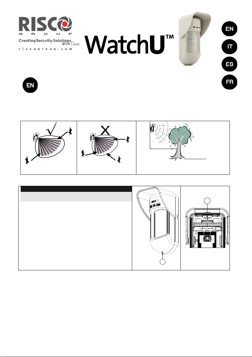
Mounting Considerations
Wall Mount Installation
Note:
The installation knockouts numbering are marked on the
back plate.
1. Open WatchU front cover
(unlock C1, Figure 1).
2. Release internal base (unlock I1, Figure 2).
3. Select mounting installation as follows:
Flat Mounting:
Open knockouts on external base (Figure 3).
B1 - B4: Wall mounting knockouts
T1: Back tamper knockout
W2 / W3: wires entry knockouts
5m (16')
Keep distance of
minimum 5m (16')
from moving objects
C1
Figure 1
Out of
Detection Range
Figure 2
I1
1
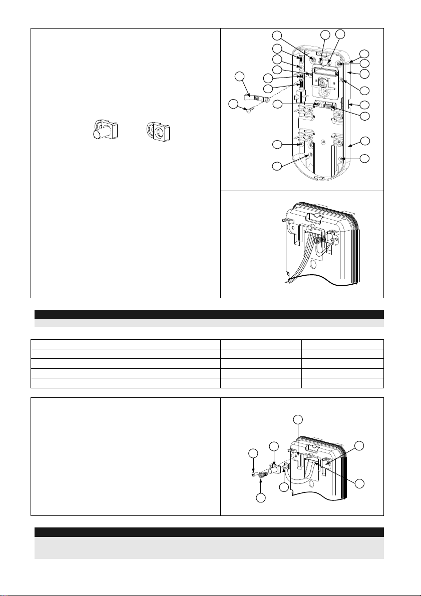
45° angle Mounting (Left side mounting)
a. Open knockouts on external base (Figure 3)
L1, L2: Left mounting knockouts
T3: Left tamper knockout
W5 / W6: Wire entry knockouts
b. Remove tamper spring.
c. Replace tamper bracket (Item 1) with
supplied flat tamper bracket (Item 2).
Item 1 Item 2
Tamper
Lever
B
A
T5
T1
T3
L1
B1
W5
W6
W3
T6
T4
T2
R1
(not visible)
B2
W9
W2
d. Insert Tamper lever B onto T5 and T3 and
secure screw A (Figure 3).
4. Insert external wires through external base W2,
W3 (Flat Mounting) or W5, W6 (Left
side
mounting) (Figure 3).
5. Secure external base to the wall.
L2
B4
Figure 3
6. Insert external wires and tamper wires through
internal base (Figure4).
7. Secure internal base to external base (lock I1,
Figure2).
8. Close the front cover (Lock C1, Figure1) after
wiring and setting DIP switches.
9. Walk test the detector.
Figure 4
Note:
For 45° right side installation use the equivalent units on the external base as follows:
Knockouts Description
Left Right
Mounting Knockouts L1, L2 R1, R2
Tamper spring knockouts T1,T3 T2,T4
Tamper screw anchor T5 T6
Wiring Knockouts W5, W6 W7, W8
Changing Back Tamper position
The back tamper is by default secured on the right
Left Side
Tamper
6
side of the internal base (rear view). If you wish to
move it to the left side (rear view), do the following
(Figure 5):
1. Remove tamper screw 1 in order to release
3
1
the tamper from position 7.
2. Ensure tamper spring 2 rests over tamper wire
base 4.
3. Ensure plastic tamper bracket 3 rests over
both 2 and 4.
4. Secure tamper screw 1 into 3 over position 6.
4
2
Figure 5
Notes:
1. Verify that you hear a "Click" when attaching the tamper spring to the wall.
2. For pole installation, the tamper can be moved to the bottom right-hand side of the internal base.
R2
(not visible)
B3
Right Side
Tamper
7
5
2
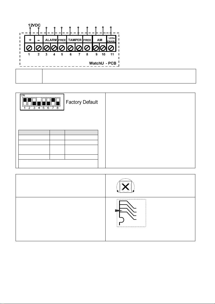
Terminal Wiring
LED
ENABLE
Used to remotely control the LEDs when DIP1 is set to ON.
Enable: input is +12V OR no terminal connection
Disable: Connect the input to 0V
DIP Switch Settings
DIP 1: LEDs operation
On: LEDs Enabled
Off: LEDs Disabled
DIP 2-3: Detection Sensitivity
Sensitivity DIP2 DIP3
Low Off Off
Mid Off On
Normal
On Off
(Default)
Maximum* On On
* In maximum sensitivity sway recognition is
disabled to achieve maximum sensitivity
DIP 4: Anti masking Sensitivity
On: High
Off: Low
DIP 5: Detector's optics
On: Barrier / Long range
Off: Wide angle
DIP 6: Red LED /3 LED
On: Red LED only
Off: 3 LEDs
DIP 7: Anti masking operation
On: Enabled
Off: Disabled
DIP 8: N/A
Microwave Adjustment
Adjust Microwave coverage area by using the
trimmer on the PCB.
Walk test
Two minutes after applying power, walk test
the protected area to verify proper operation.
For installations on uneven surfaces slide the
PCB inside the internal base to the
appropriate setting according to the desired
height (1.0m, 1.5m, 2.2m, 2.7m) as printed on
the bottom left corner of the PCB.
MAX
MIN
PCB
1.00M
1.50M
2.20M
2.70M
3
LEDs Display
LED State Description
YELLOW
GREEN
RED
All LED s
Notes:
1. DIP-Switch 1 should be in ON position to enable LED indications.
2. Only one LED is active at any one time. For example, in the case of both PIR and MW detection, either the
steady YELLOW LED or the steady GREEN LED is displayed (the first to detect), followed by the Alarm RED
LED.
Steady Indicates PIR detection
Flashing Indicates AM (Anti mask) detection
Steady Indicates MW detection
Steady Indicates ALARM
Flashing (One
Unit initialization on power up
after another)
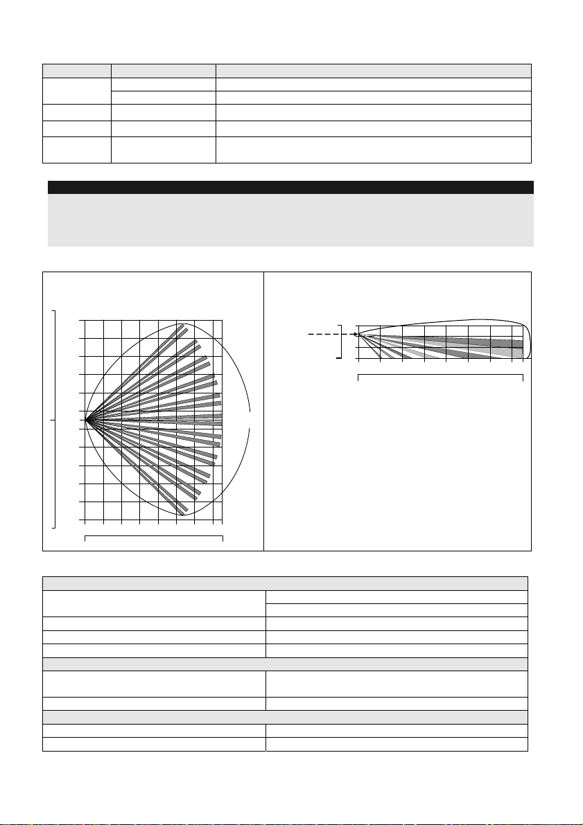
Lens Types
Wide angle lens (RL300) /
40
11
9
30
7
20
5
3
10
1
0
0
1
3
10
5
20
7
9
30
11
40
Feet
0
Top view
2468100121415
10
20
30 40 50
90°
Typical
Installation
Height:
2.2m (7'2")
Wide angle lens (RL300):
Side View
Feet
3
10
1
0
0
Meters
2468100121415
Feet
0
20
10
30 40 50
Technical Specification
Electrical
Current consumption 45mA at 12 VDC (Stand by)
70mA at 12 VDC (MAX with LED ON)
Voltage requirements 9 -16 VDC
Alarm contacts 24 VDC, 0.1A
AM contacts 24 VDC, 0.1A
Physical
Size:
220 x 115 x 123mm (8.7 x 4.5 x 4.85 in.)
LxWxD
Weight 0.632 Kg (1.4lb)
Environmental
RF immunity (30MHz to 2GHz): 40V/m
Operating/Storage temperature -30°C to 60°C (-22°F to 140°F)
* PIR technology is limited in rough environmental conditions.
4
Introduzione
Il rivelatore da esterno Doppia Tecnologia WatchU di RISCO Group è un dispositivo a
microprocessore che elabora i segnali rilevati tramite due canali all’infrarosso passivo (PIR) e due
canali a microonda (MW).
Considerazioni per l’installazione
[Vedi pagina 1]
Installazione a parete
[Vedi Figure 1-4, pagine 1-2]
Nota:
I numeri di riferimento dei fori a sfondare per
l’installazione sono marcati sulla base posteriore.
1. Aprire il coperchio frontale del WatchOUT.
(Svitare C1, figura 1).
2. Sganciare la base interna (svitare I1, fig. 2).
3. Selezionare l’altezza di installazione come
segue:
Installazione piana
Aprire i fori a sfondare della base esterna (fig. 3)
B1 - B4: Fori a sfondare per installazione
a parete.
T1: Foro a sfondare per il tamper
antirimozione
W2 / W3: Fori a sfondare per il
passaggio cavi
Installazione angolare di 45°
(installazione a sinistra)
a. Aprire i fori a sfondare della base esterna
(fig. 3)
L1, L2 : Fori a sfondare per lato
sinistro
T3: Foro a sfondare per tamper lato
sinistro
b. W5 / W6: Fori a sfondare per passaggio
caviRimuovere la molla del tamper
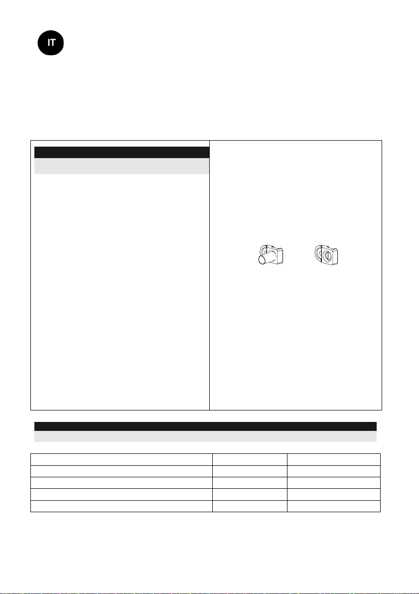
c. Sostituire la staffa (Item 1) con l’altra
fornita (Item 2).
Item 1 Item 2
d. Inserire la leva B del tamper in T5 e T3 e
stringere la vite A (figura 3)
4. Inserire I cavi esterni attraverso la base
esterna W2, W3 (Installazione piana) o
W5,
W6 (Installazione a sinistra) (figura 3).
5. Fissare la base esterna alla parete.
6. Inserire i cavi esterni e i cavi del tamper
attraverso la base interna. (figura 4).
7. Fissare la base interna a quella esterna
(bloccare I1, figura 2).
8. Chiudere il coperchio frontale (bloccare
C1, figura 1) dopo aver cablato l’unità e
predisposto i microinterruttori.a.
Nota:
Per installazioni a 45° lato destro usare le equivalenti predisposizioni sulla base esterna come segue:
Descrizione fori a sfondare Sinistra Destra
Fori a sfondare per il fissaggio della base L1, L2 R1, R2
Foro a sfondare per la molla del tamper T1,T3 T2,T4
Punto di fissaggio vite tamper T5 T6
Fori a sfondare per passaggio cavi W5, W6 W7, W8
5
 Loading...