

Risco watchout 312PR Installation Instructions Manual
Portuguese
Français
Español
Italiano
English
PIR Outdoor Detector
Rivelatore da Esterno ad Infrarosso Passivo
Detector de Exterior PIR
Détecteur IRP extérieur
Detector Infravermelho Passivo para área Externa
WatchOUT 312PR
Installation Instructions - Relay & BUS Modes
Istruzioni per l’installazione in modalità Relé e BUS
Instrucciones de Instalación - Modos Relé y BUS
Guide d'installation - Modes Relais et BUS
Instruções de Instalação - Modos Relé & BUS
2 WatchOUT PIR Installation Manual

WatchOUT PIR Installation Manual 3
English
Table of Contents
Relay Mode Installation 4
Introduction 4
Mounting 4
Mounting Considerations 4
Wall Mount Installation 6
Flat Mounting: 6
45° angle Mounting (Left side mounting) 6
Changing Back Tamper position 7
Terminal Wiring 7
DIP Switch Settings 8
Detection Range Adjustment 8
Walk test 9
LEDs Display 10
Relay Mode / Bus Mode Jumper 10
Optional Swivel Installation (Not Supplied) 10
Wall Mounting 10
Swivel Conduit Mounting
(using Conduit Metal Swivel Adaptor - CSMA, Figure 8, Detail A) 11
Replacing Lenses 12
Technical Specification 13
Ordering Information 13
Accessories Kits 13
BUS Mode Installation 14
Introduction 14
Terminal Wiring 14
Cover and Back Tamper 14
Cover Tamper Only 14
Cover Tamper to Zone Input 14
DIP Switch Settings 14
ProSYS Programming 15
4 WatchOUT PIR Installation Manual
Relay Mode Installation
Introduction
RISCO Group's WatchOUT 312PR, is a unique detector with signal processing based on two
Passive Infrared (PIR) channels. The detector has an adjustable detection range. The detector
can operate as a regular relay detector connected to any control panel, or as a BUS accessory
when connected to RISCO Group's ProSYS control panel via the RS485 BUS, thus having unique
remote control and diagnostic capabilities.
The following instructions describe the installation of the WatchOUT in Relay & BUS mode.
Mounting
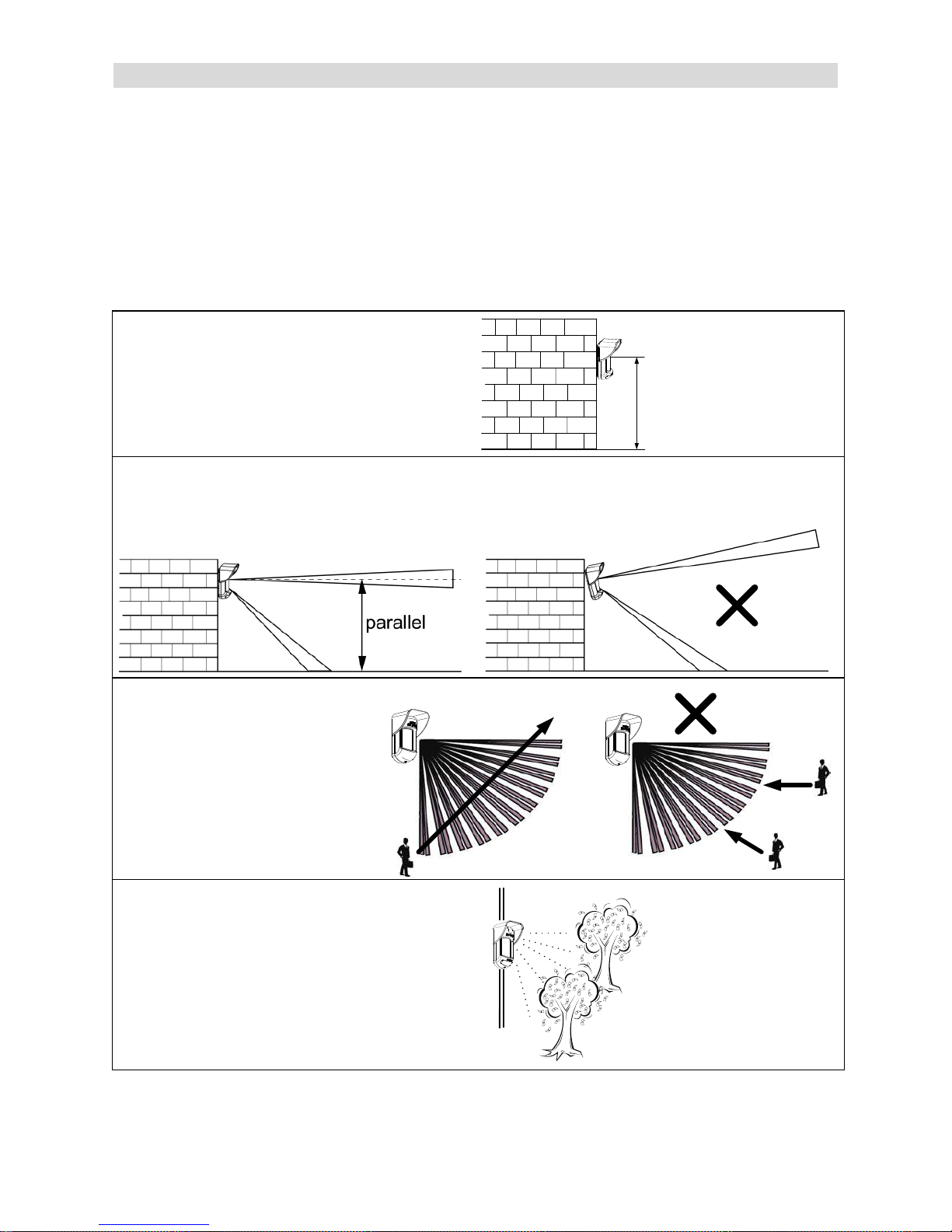
Mounting Considerations
1. Installation Height: 0.8m - 1.2m
(2'8" – 3'11")
Typical Installation Height: 1m (3'3")
0.8m -1.2m
(2'8" - 3'11")
2. To ensure maximum operational reliability, install the detector perpendicular to the ground so
that the upper detection area is parallel to the ground.
ü
3. For optimum detection,
select a location that is likely
to intercept an intruder
moving across the coverage
pattern.
ü
4. Avoid pointing the detector to moving
objects (swaying trees, bushes etc.)
WatchOUT PIR Installation Manual 5
English
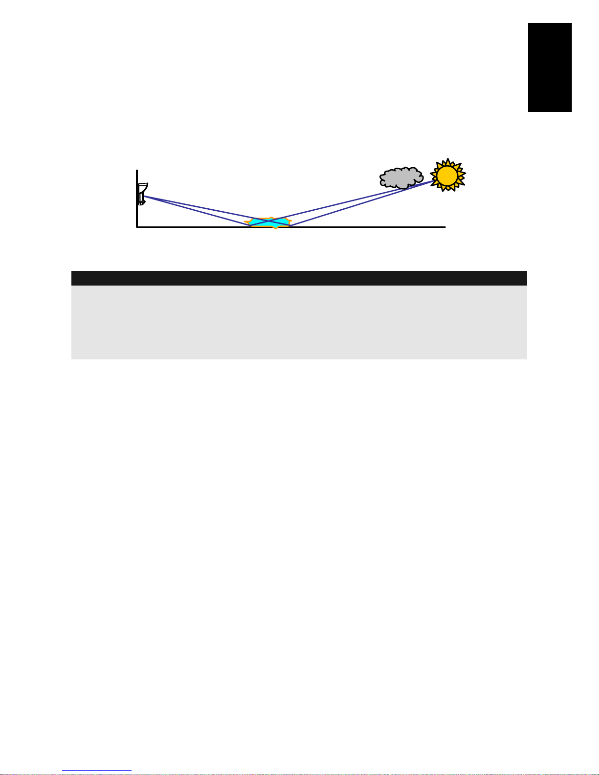
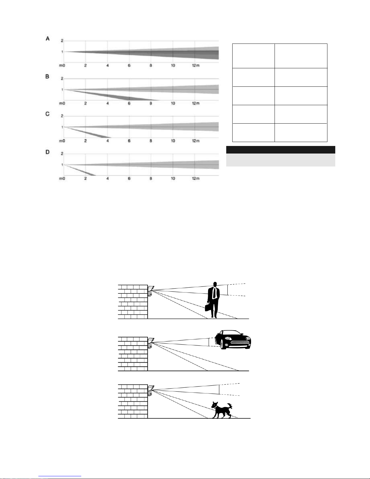
Installing the WatchOUT 312PR in challenging situations
In the following situations, rapid and significant infrared radiation changes can happen in both
PIR channels together, resulting in false alarms and therefore care should be taken.
1. Situations in which metal and/or glass objects measuring over 70cm (2‟4”) in height from the
ground are in the field of view of the detector (cars, metal gates, shutters, metal walls,
windows, etc.)
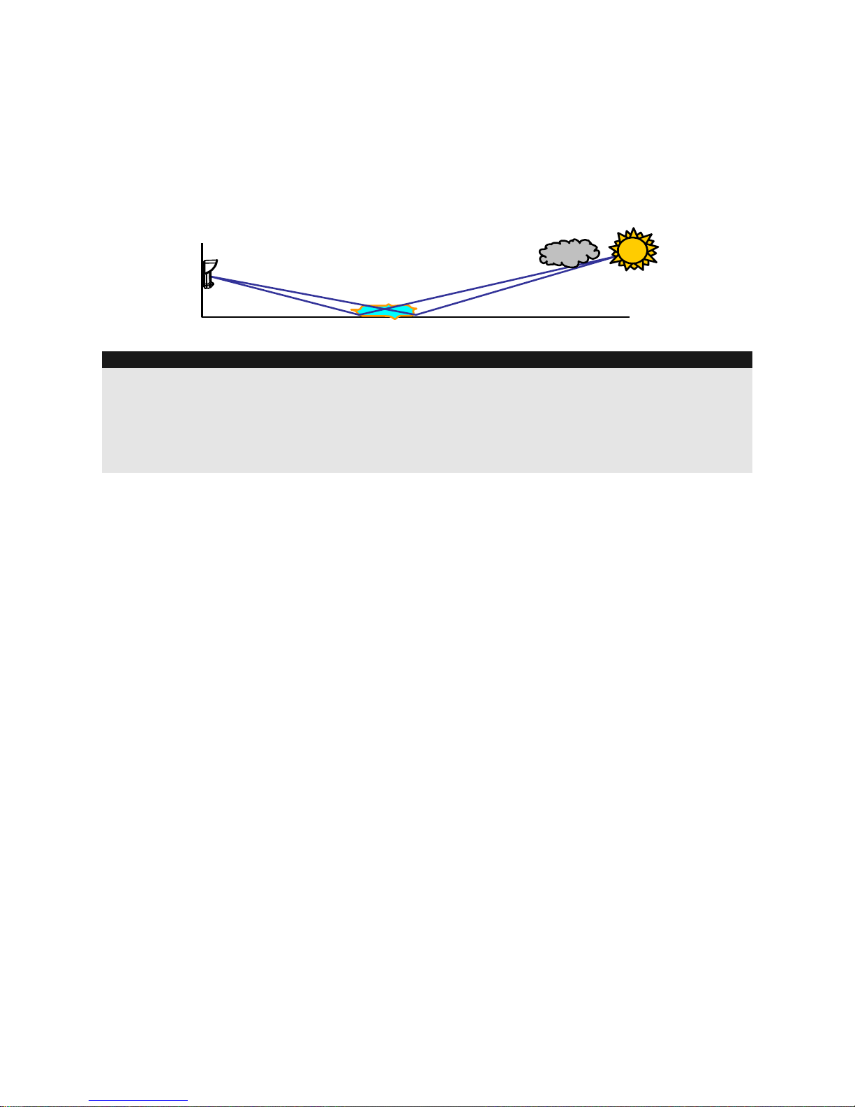
2. Situations in which a reflective surface on the ground larger than 1m (3‟4”) in diameter may
cause reflection into the detector‟s lens. Examples of a reflective surface on the ground are a
puddle, wet road or car park, smooth concrete or asphalt surface, swimming pool, etc.
Water Reflection
NOTES:
1. Please note that any outdoor PIR detector will require reduction in range to a shorter distance than the car,
metal object or surface reflection (so that these objects won‟t be protected) in order to eliminate false
alarms.
2. For full 15m (50’) coverage in the above situations, it is highly recommended to install the
WatchOUT DT, the only outdoor detector with 2 PIR channels and 2 Microwave channels.
3. WatchOUT detectors include high quality Silicon filters on the PIR sensors for blocking out white light
interferences. These filters are not intended to block infrared thermal radiation.
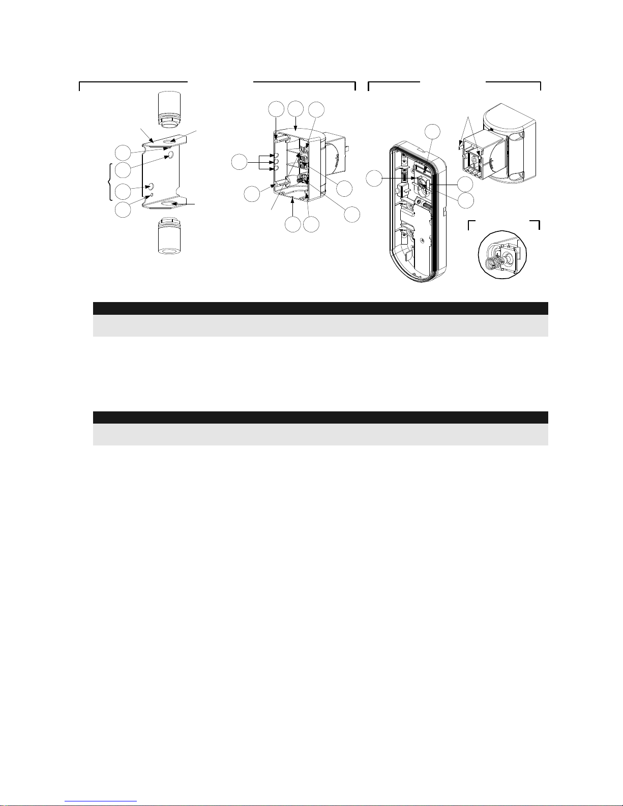
6 WatchOUT PIR Installation Manual
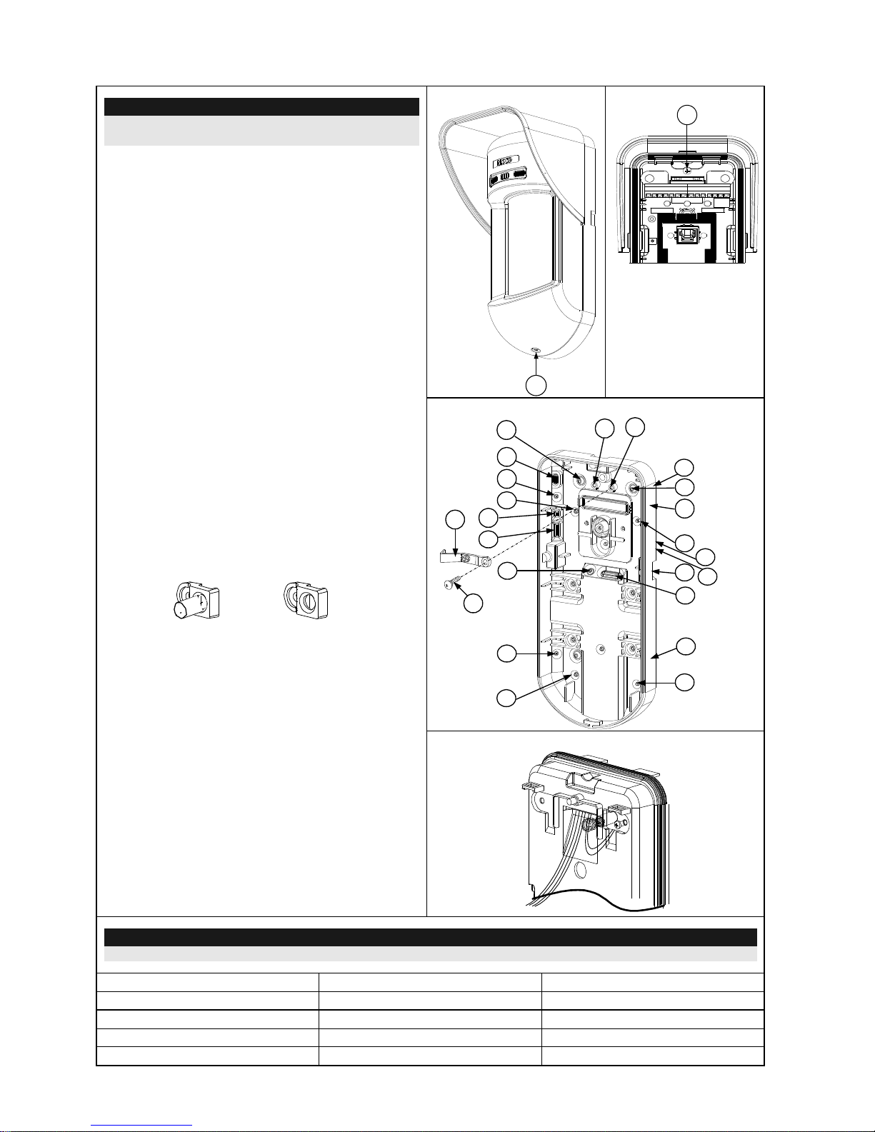
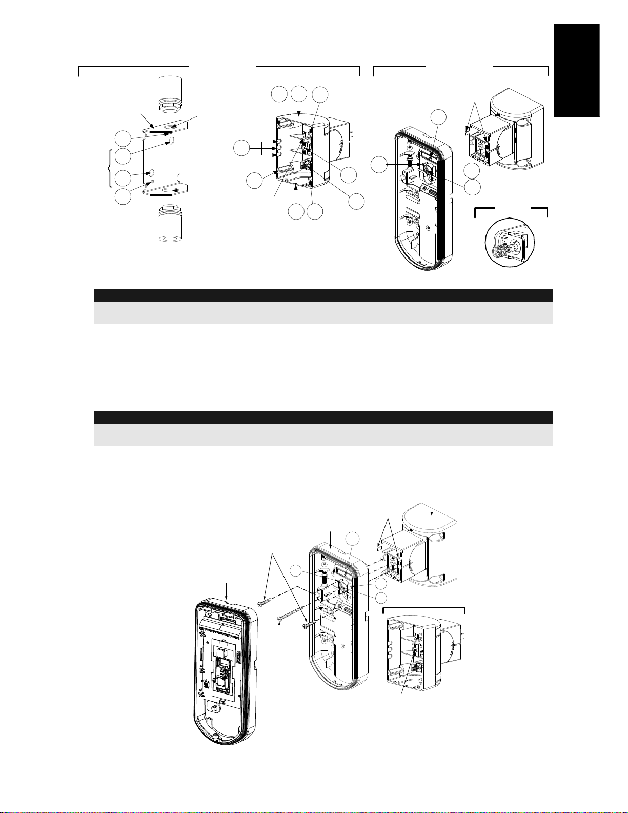
Wall Mount Installation
Note:
The installation knockouts numbering are marked on
the back plate.
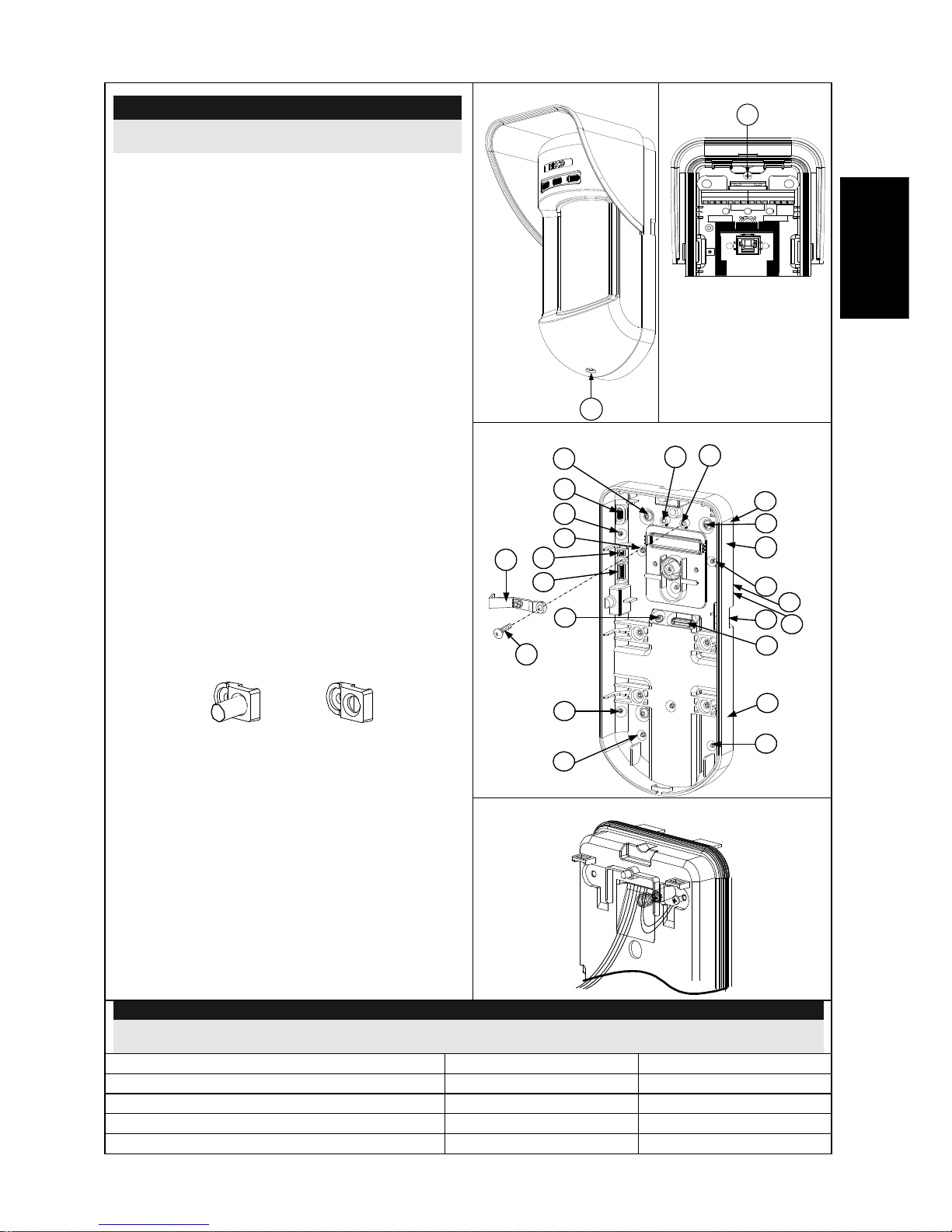
1. Open WatchOUT front cover (unlock C1,
Figure 1).
2. Release internal base (unlock I1,
Figure 2).
3. Select mounting installation as follows:
Flat Mounting:
Open knockouts on external base (Figure 3).
B1 - B4: Wall mounting knockouts
T1: Back tamper knockout
W2 / W3: wires entry knockouts
45° angle Mounting (Left side
mounting)
a. Open knockouts on external base
(Figure 3).
L1, L2: Left mounting knockouts
T3: Left tamper knockout
W5 / W6: Wire entry knockouts
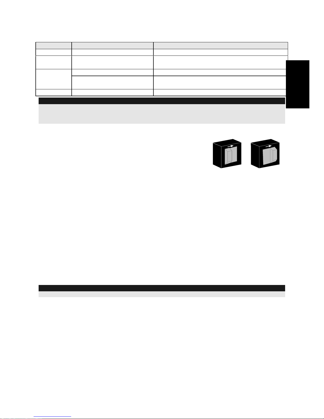
b. Remove tamper spring
c. Replace tamper bracket (Item 1) with
supplied flat tamper bracket (Item 2).
Item 1
Item 2
d. Insert Tamper lever B onto T5 and T3
and secure screw A (Figure 3)
4. Insert external wires through external base
W2, W3 (Flat Mounting) or W5, W6 (Left
side mounting)(Figure 3).
5. Secure external base to the wall.
6. Insert external wires and tamper wires
through internal base (Figure 4).
7. Secure internal base to external base (lock
I1, Figure 2).
8. Close the front cover (Lock C1, Figure 1)
after wiring and setting DIP switches.
9. Walk test the detector.
Figure 1
C1
Figure 2
I1
Figure 3
Tamper
Lever
A
T5
T1
B2
W9
B3
W2
L1
T3
B1
L2
W3
B4
R1
R2
T2
T6
(not visible)
T4
W5
W6
(not visible)
W7
W8
B
(not
visible)
(not
visible)
Figure 4
Note:
For 45° right side installation use the equivalent units on the external base as follows:
Knockouts Description
Left
Right
Mounting Knockouts
L1, L2
R1, R2
Tamper spring knockouts
T1,T3
T2,T4
Tamper screw anchor
T5
T6
Wiring Knockouts
W5, W6
W7, W8
WatchOUT PIR Installation Manual 7
English
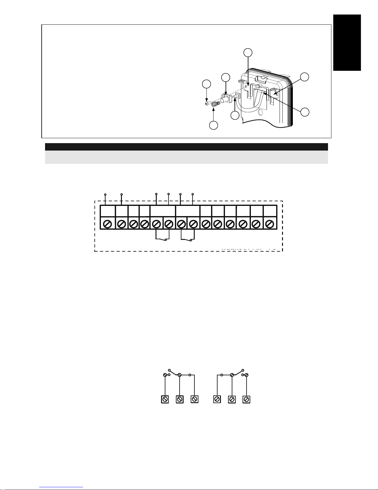
Changing Back Tamper position
The back tamper is by default secured on the
right side of the internal base (Rear view). If
you wish to move it to the left side (rear view),
do the following (Figure 5):
1. Remove tamper screw 1 in order to
release the tamper from position 7.
2. Ensure tamper spring 2 rests over tamper
wire base 4.
3. Ensure plastic tamper bracket 3 rests over
both 2 and 4.
4. Secure tamper screw 1 into 3 over
position 6.
Figure 5
Left Side
Tamper
Right Side
Tamper
3
6
1
2
4
7
5
Notes:
a. Verify that you hear a "Click" when attaching the tamper spring to the wall.
b. For pole installation, the tamper can be moved to the bottom right-hand side of the internal base.
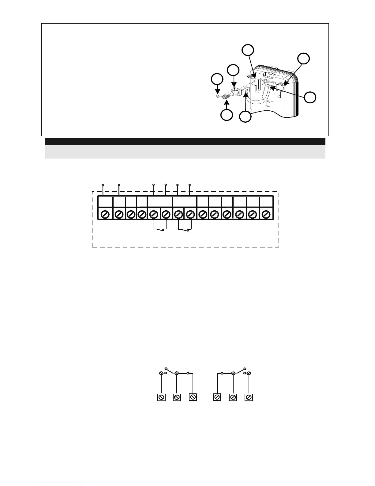
Terminal Wiring
12VDC
N.C N.C
+ -
LED
ENABL
ALARM
FREE
N.O COM
GRN
YEL
TAMPER
FREE
N.C
WatchOUT PIR - PCB
+,-
12 VDC
YELLOW
N/A (Used only for BUS mode installation)
GREEN
N/A (Used only for BUS mode installation)
ALARM
N.C relay, 24VDC , 0.1A
TAMPER
N.C relay, 24VDC , 0.1A
FREE
A free terminal that can be used to connect wires and EOL resistors
LED
ENABLE
Used to remotely control the LEDs when DIP1 is set to ON (used in high security
environments).
LED Enable: input is +12V OR no terminal connection.
LED Disable: Connect the input to 0V.
N.O
Programmable auxiliary relay terminals. This relay is used to activate auxiliary
units such as cameras or lighting when an alarm is triggered.
The operation of the auxiliary relay depends on the settings of DIP switches 4-7.
NORMAL
N.O
COM
N.C
ALARM
N.C
COM
N.O
COM
N.C
WatchOut 312PR - PCB
8 WatchOUT PIR Installation Manual
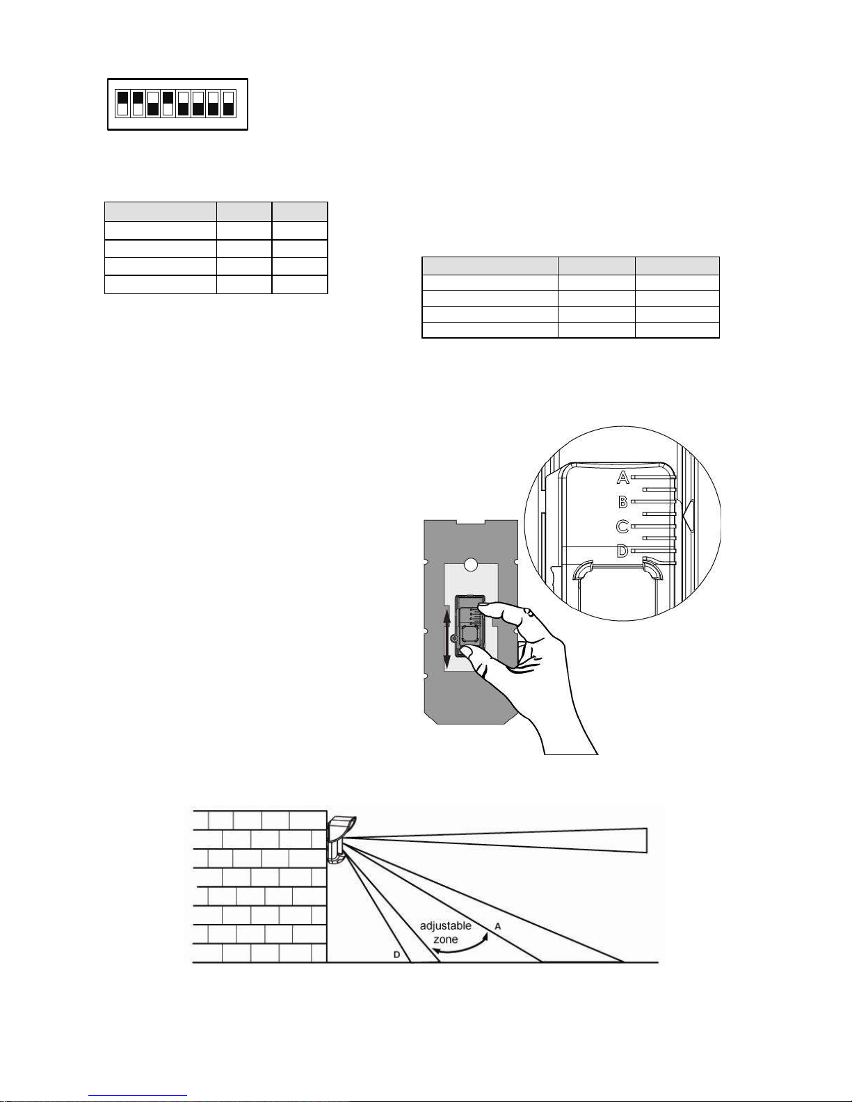
DIP Switch Settings
1 2 3 4 5 6 7 8
ON
Factory
Default
DIP 1: LEDs operation
On: LEDs enabled
Off: LEDs disabled
DIP 2-3: PIR Detection Sensitivity
Sensitivity
DIP2
DIP3
Low
Off
Off
Mid
Off
On
Normal
On
Off
Maximum
On
On
DIP 4: Auxiliary relay control
ON: Enabled
OFF: Disabled
DIP 5: Used to define the auxiliary relay operation
following an alarm condition, depending on
Day/Night time (defined by 24 Hours / Night
Photocell)
ON (Night): Auxiliary relay is activated only
during nighttime.
OFF (24 Hours): Auxiliary relay is activated
24 hour
DIP 6-7: Defines the time duration that the auxiliary
relay is activated
Activation Time
Switch 6
Switch 7
2.2 seconds
OFF
OFF
2.0 Minutes
OFF
ON
4.0 Minutes
ON
OFF
8.0 Minutes
ON
ON
DIP 8: Red LED /3 LED
ON: Red LED only
OFF: 3 LEDs
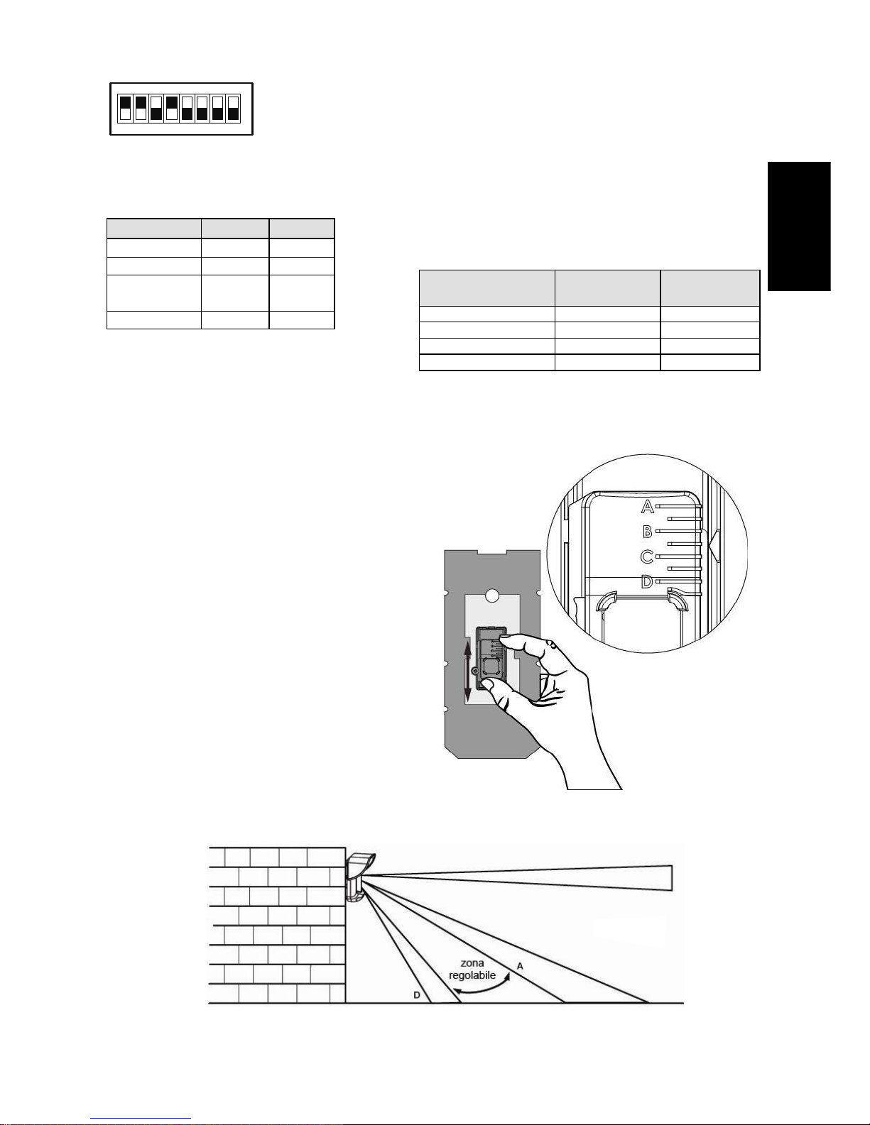
Detection Range Adjustment
Slide the moving PIR to the desired
position, see figure 6.
The range of the lower detection area
determines the detection range.
The upper PIR is fixed and its detection
area is parallel to the ground at all times.
The lower detection area changes from
2m to 12m depending on the location of
the moving PIR. Therefore, the detection
range is established according to the
location of the lower PIR since both the
upper and the lower PIR should be
triggered in order to activate an alarm.
Figure 6
WatchOUT PIR Installation Manual 9
English
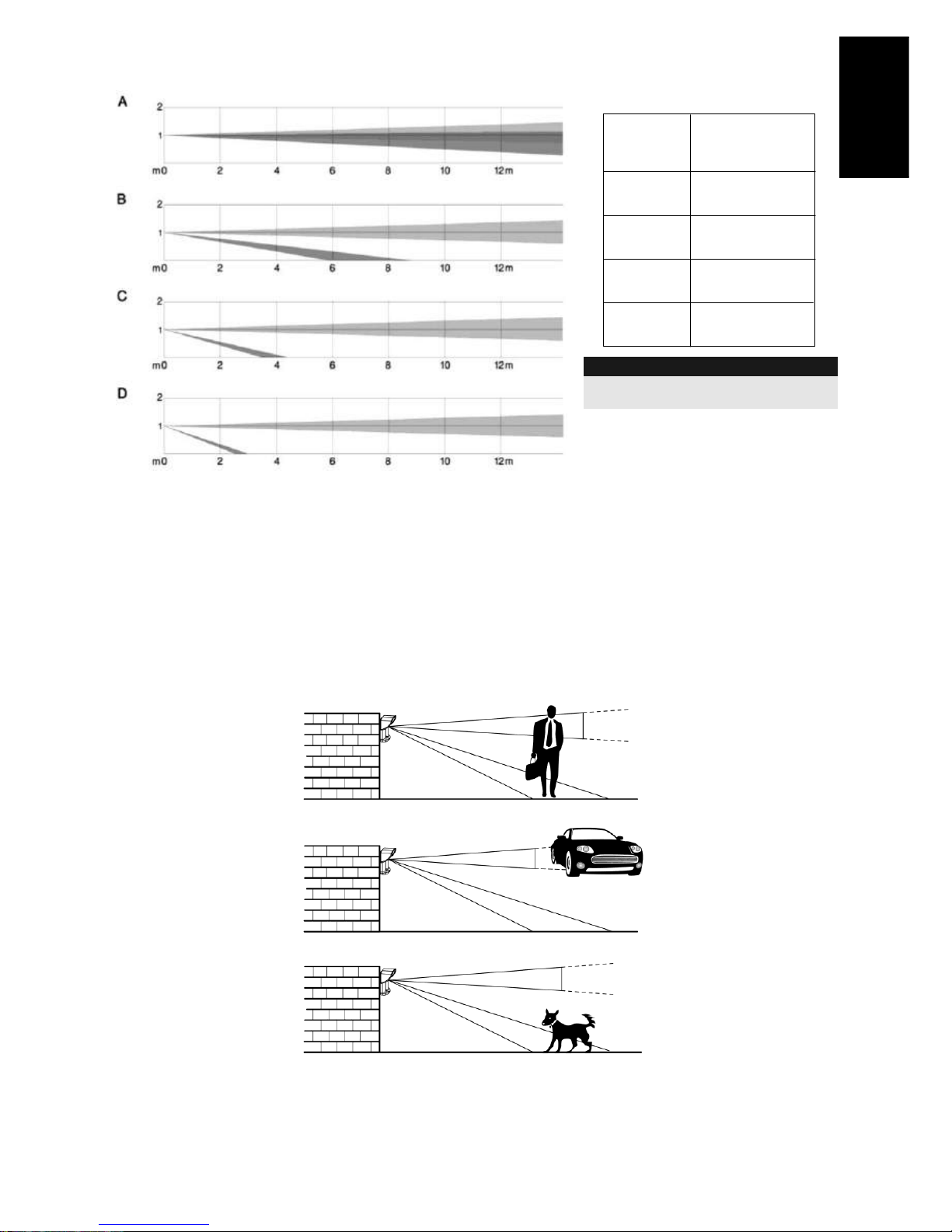
Detection patterns (side view):
Detection range with 1m (3'3")
installation height:
POSITION
MAX.
DETECTION
LENGTH*
A
B
C
D
12m
(40')
7m
(23')
3m
(9'10")
2m
(6'6")
* NOTE:
Length may vary according to
environmental thermal conditions.
Walk test
Two minutes after applying power, walk test the protected area to verify proper operation.
Adjust the moving PIR for required detection range and reliability.
IMPORTANT!
Both upper and lower detection areas must be blocked simultaneously for detection to occur, see
figure 7 below.
NO DETECTION
NO DETECTION
DETECTION
Figure 7

10 WatchOUT PIR Installation Manual
LEDs Display
LED
State
Description
GREEN
Steady
Indicates upper PIR detection
YELLOW
Steady
Indicates moving PIR detection
RED
Steady
Indicates ALARM (Simultaneous 2 PIR channels)
Flashing
Indicates malfunctioned communication with ProSYS (BUS mode
only)
All LEDs
Flashing
(One after
another)
Unit initialization on power up
Notes:
1. DIP-Switch 1 should be in ON position to enable LED indications.
2. Only one LED is active at any one time. For example, in the case of both PIR channels detection, either the
steady yellow LED or the steady green LED is displayed (the first to detect), followed by the alarm red LED.
Relay Mode / Bus Mode Jumper
J-BUS jumper (located on the PCB between the red and
green LEDs) is used to define the detector’s mode of
operation as follows:
Relay
Mode
BUS Mode
O
N
O
N
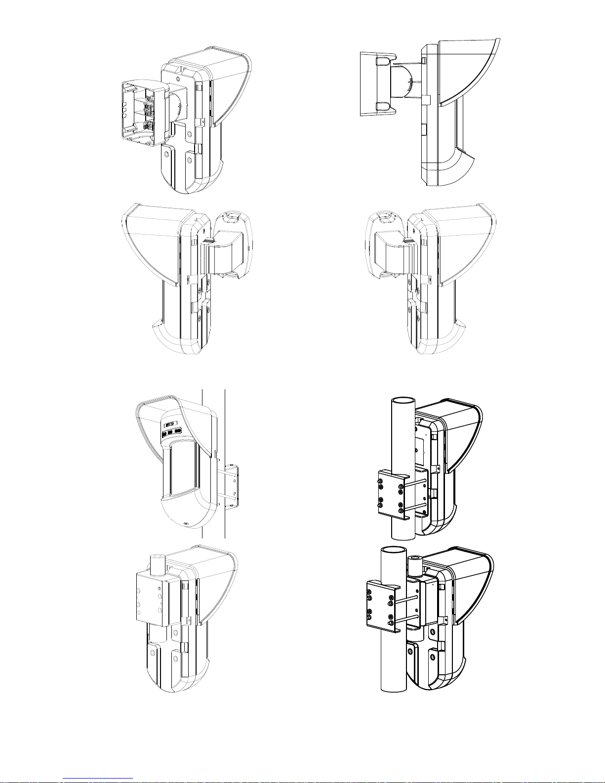
Optional Swivel Installation (Not Supplied)
Please follow the instructions below for mounting the detector with the Standard Swivel:
1. Open WatchOUT front cover (Unlock C1, Figure 1).
2. Release internal base (Unlock I1, Figure 2).
3. Open knockouts on external base (Figure 8, Detail B)
W1: Wires knockout
S1,S2: Knockouts for securing external base to Standard Swivel
S3: External base locking screw knockout
4. On the swivel accessory remove the required swivel cable wiring knockout S2, S7 or S9
(Figure 8, Detail A).
5. Remove back tamper from the internal base (see “Changing Back Tamper Position"
paragraph) and connect it to S5 (Figure 8, Detail A) on the Standard Swivel.
6. Select the mounting installation as follows:
Note:
Ensure that you see the engraved UP mark on the upper front face of the swivel.
Wall Mounting
a. Insert external cable wiring through knockouts S2, S7 or S9 and extract them (including the
tamper wires) through the Swivel Wires Passage (Figure 8, Detail B).
b. Secure swivel to the wall through holes S1, S3, S6 and S8.
WatchOUT PIR Installation Manual 11
English
Swivel Conduit Mounting (using Conduit Metal Swivel Adaptor - CSMA, Figure 8, Detail A)
S1
S2
S3
S9
S8
S7 S6
S5
S4
Tamper
(see Detail C)
Swivel Wires
Passage
Tamper
Spring
Holes
Ø 21 mm
Ø 16 mm
CSMA
M1
M2
M3
M4
Detail A Detail B
S1
W1
S2
S3
Snaps
Standard Swivel
Detail C
Figure 8
Note:
The CSMA is required when wiring is in a pipe external to the wall. It should be ordered separately P/N
RA300S.
a. Choose the direction upon which to mount the CSMA according to the required diameter:
16mm (0.63 inches) or 21mm (0.83 inches).
b. Insert conduit to the CSMA.
c. Secure CSMA to the wall through points (M1, M4).
d. Insert external cables and tamper wires from the conduit through the swivel wires passage
of the swivel (Figure 8, Detail A).
e. Secure swivel to the wall through holes S1, S3, S6 and S8.
Note:
The Tamper spring S5 (Figure 8) should make contact with the wall through the tamper spring holes M2 or
M3 on the CSMA. Make sure to hear the tamper "Click" when connecting to the wall.
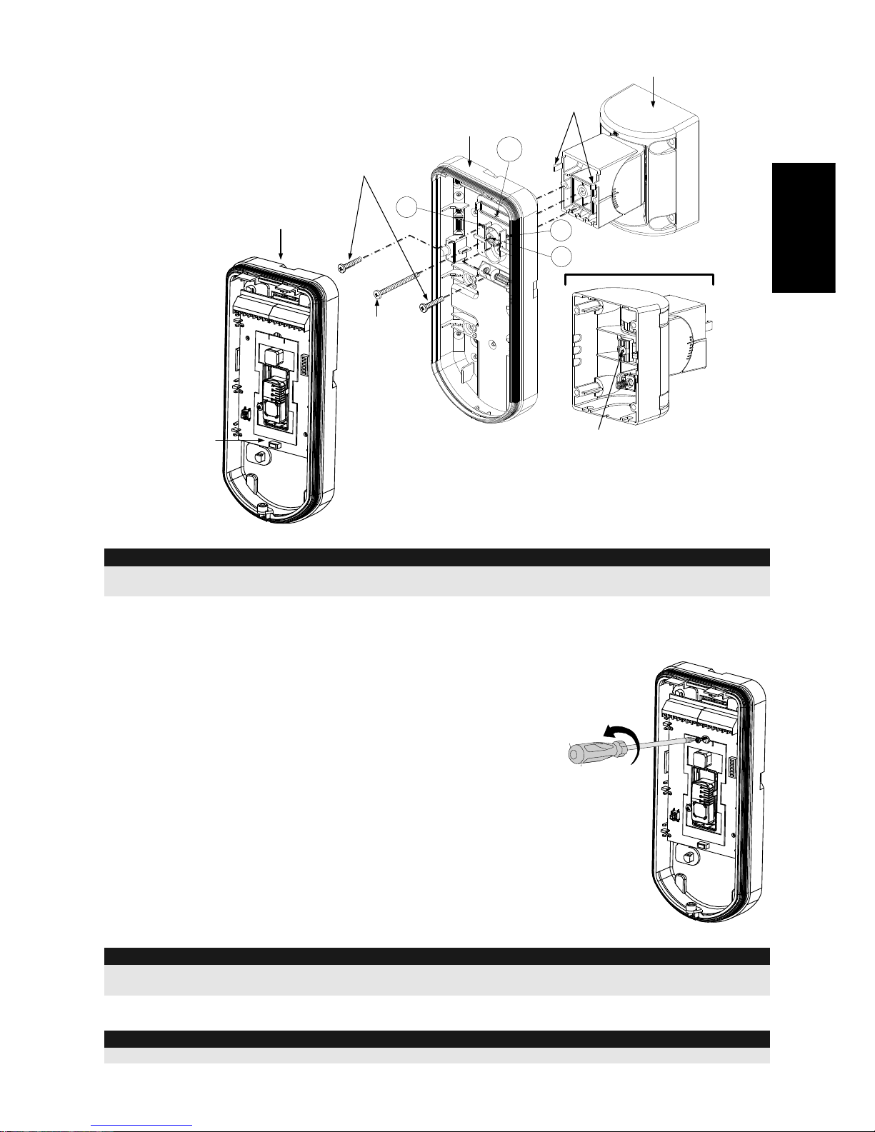
7. Insert tamper wires and external cable wiring from Standard Swivel through knockout W1 on
the external base (Figure 8, Detail B).
8. Connect the external base to the swivel using the dedicated snaps (Figure 9).
External Base
Angle Locking
Screw
(See Note 2)
See Detail A
Swivel to External Base
Connecting Screws
Detail A
Swivel Assy
Connecting Screw
(See Note)
Snaps
S1
W1
S2
S3
Internal Base
PCB
Figure 9
12 WatchOUT PIR Installation Manual
NOTE:
Do not open or close the Swivel Assy Screw since it is used for connecting the swivel parts only.
9. Secure external base to swivel with two screws fastened to knockouts S1 and S2 (Figure 9).
10. Insert the supplied angle locking screw from the external base through the angle locking screw
knockout S3 on the external base to the standard swivel (Figure 9).
11. Rotate the Swivel to the desired position. Once the
Standard Swivel is in the desired position, secure
the angle locking screw.
IMPORTANT!
Take care not to tilt the detector upwards and
downwards. The detector should remain
perpendicular to the ground for maximum detection
and reliability.
12. Line up the internal base onto the external base.
Insert all wiring cables through the internal base.
13. Secure internal base to external base (Lock I1,
Figure 2).
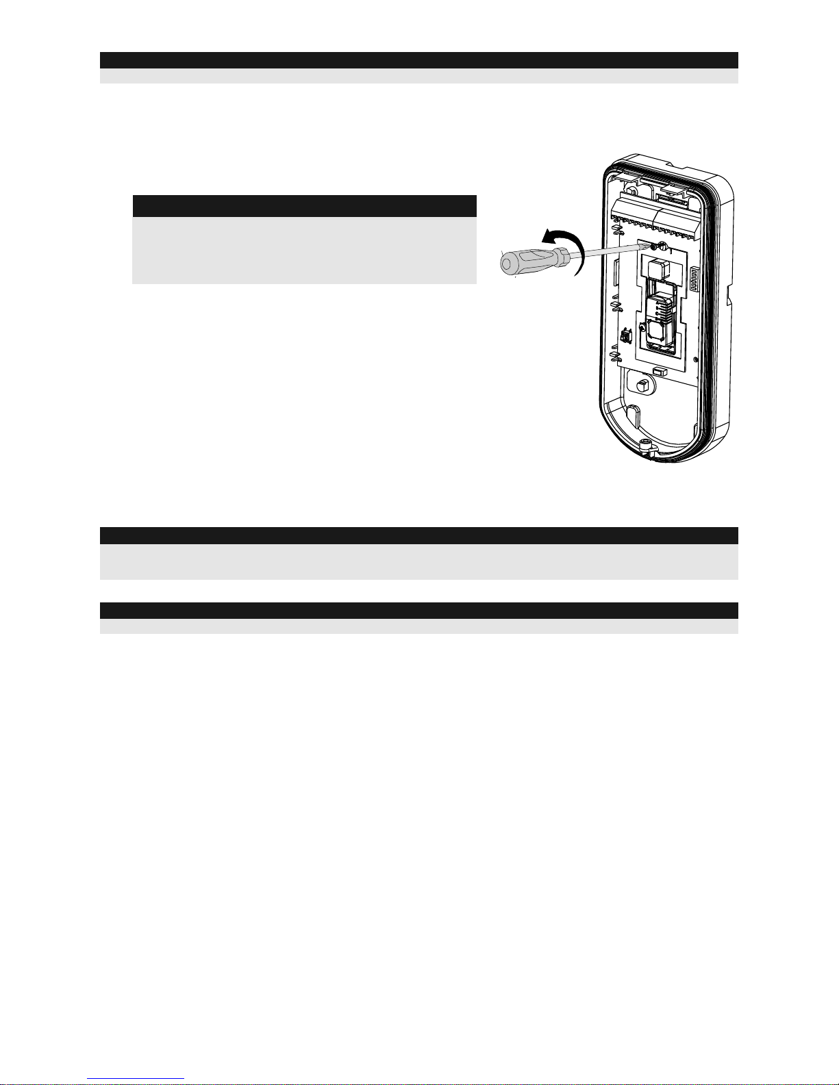
14. To readjust the Standard Swivel when the PCB is
installed (Figure 10):
a. Bend down the black foam located below the
RED LED on the PCB (enough to reach the
Swivel locking screw).
b. Use a Philips screwdriver to release the
locking screw (see Figure 10).
c. Rotate the Swivel to the desired position.
d. Secure the angle locking screw.
Figure 10
NOTE:
When marks on the two movable parts are aligned (Figure 9), the Swivel is in 0 vertical /horizontal position.
Each click from this position represents shifting of 5 in vertical / horizontal position.
15. Close the front cover (Lock C1, Figure 1) and walk test the detector.
NOTE:
The screw has to pass through External Base and locked to the swivel.
Replacing Lenses
1. Unlock the six screws that hold the lens holding sleeve from the back of the front cover.
2. To release the protective sleeve, gently push the lens from the external side of the front cover.
3. Disconnect the lens from the sleeve by gently pushing the lens clips that secure it to the
sleeve.
4. Replace the lens. Place the 4 clips of the lens into the matching holes on the sleeve.
5. Insert the protective sleeve back into place on the front cover. Pay attention to place the
sleeve over the sealing rubber.
6. Secure the 6 holding screws back to their place.
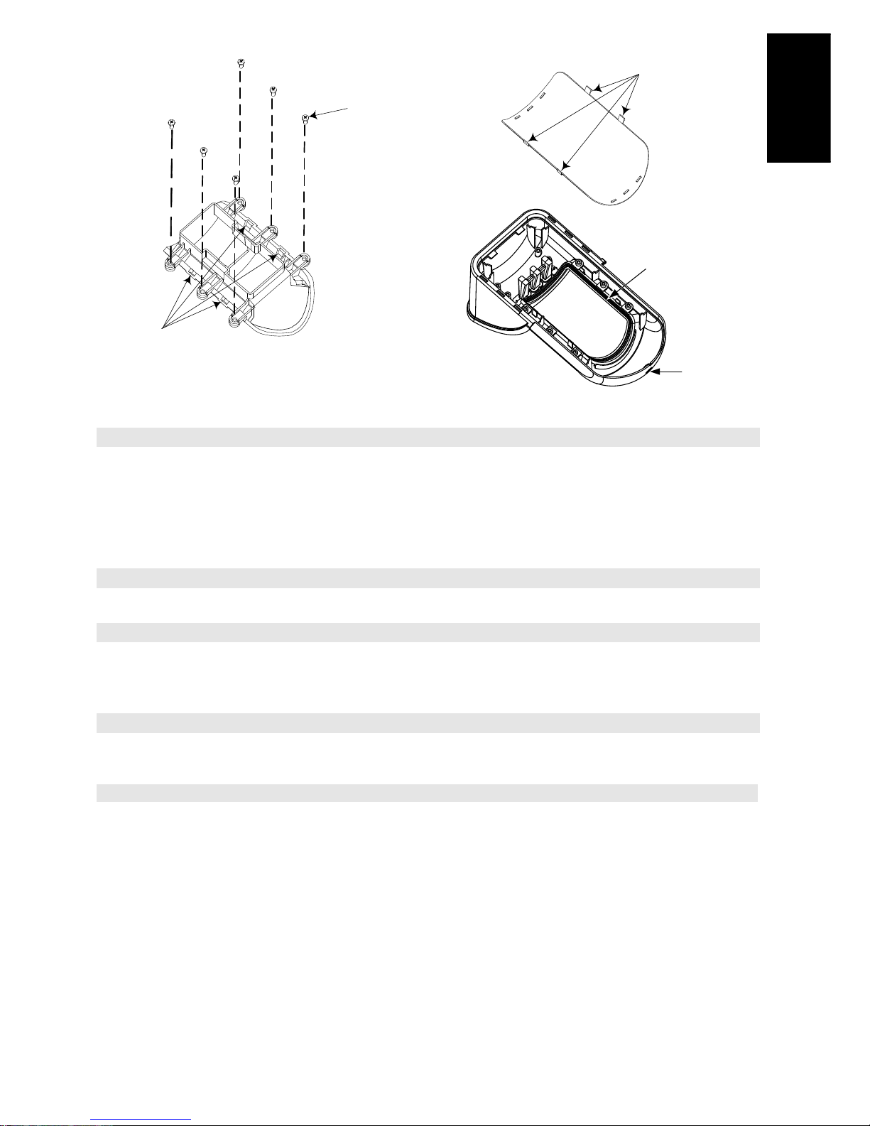
WatchOUT PIR Installation Manual 13
English
Sleeve Locking
Screws
Lens Protecting
Sleeve
Holes for
Lens Clips
Lens Locking
Clips
Sealing Rubber
Front Cover
Locking Screw
Technical Specification
Electrical
Current consumption (Relay
Mode)
31mA at 12 VDC (Stand by)
44mA at 12 VDC (MAX with LED ON)
Current consumption (BUS
Mode)
34mA at 12 VDC (Stand by),
47mA at 12 VDC (Max. with LED ON)
Voltage requirements
9 -16 VDC
Alarm contacts
24 VDC, 0.1A
Auxiliary Relay
30 VDC, 1A
Physical
Size (including hood)
LxWxD
220 x 115 x 123mm (8.7 x 4.5 x 4.85 in.)
Environmental
Operating/Storage temperature
-30°C to 60°C (-22°F to 140°F)
* PIR technology is limited in rough environmental conditions.
Ordering Information
Model
Description
WatchOUT 312PR
WatchOUT PIR
Accessories Kits
Model
Description
Weight
RA300S
RA300P
Standard Swivel Kit
WatchOut Pole Adaptor Kit
0.21 Kg (0.46 lb)
0.25 Kg (0.55 lb)
14 WatchOUT PIR Installation Manual
BUS Mode Installation
Introduction
The information in this section relates to WatchOUT 312PR installation in BUS Mode only. Up to
32 bus detectors can be installed on the ProSYS RS485 bus, saving cabling time and enabling
remote control and diagnostics.
Terminal Wiring
+,-
Used for the connection of 12VDC power supply. Connect the (+) terminal to
the AUX RED and the (–) terminal to the COM BLK of the ProSYS terminals
YELLOW
Used for data communication with the ProSYS. Connect to the terminal to the
BUS YEL of the ProSYS
GREEN
Used for data communication with the ProSYS. Connect to the terminal to the
BUS GRN of the ProSYS
TAMPER
Used for the wiring for tamper detection, see below
LED
ENABLE
Used for the wiring for tamper detection, see below
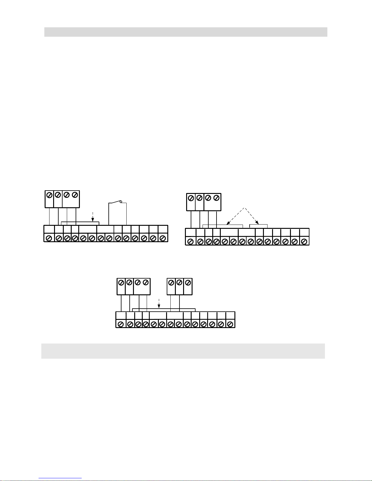
Cover and Back Tamper
+
-
LED
ENABL
ALARM
FREE
N.O COM
GRN
YEL
TAMPER
FREE
N.C
COM
BLK
BUS
GRN
YEL
BUS Mode:
Cover + Back tamper wiring
BACK
TAMPER (N.C)
ProSYS
Short
AUX
RED
Cover Tamper Only
+
-
LED
ENABL
ALARM
FREE
N.O COM
GRN
YEL
TAMPER
FREE
N.C
COM
BLK
BUS
GRN
YEL
BUS Mode:
Cover Tamper Wiring
ProSYS
Short
AUX
RED
Cover Tamper to Zone Input
COM
BLK
BUS
GRN
YEL
BUS Mode:
Cover Tamper to Zone Input
ProSYS
BUS
Short
COM
Z1 Z2
Zone
Input
AUX
RED
+ -
LED
ENABL
ALARM
FREE
N.O COM
GRN
YEL
TAMPER
FREE
N.C
DIP Switch Settings
DIP Switch
Number
Description
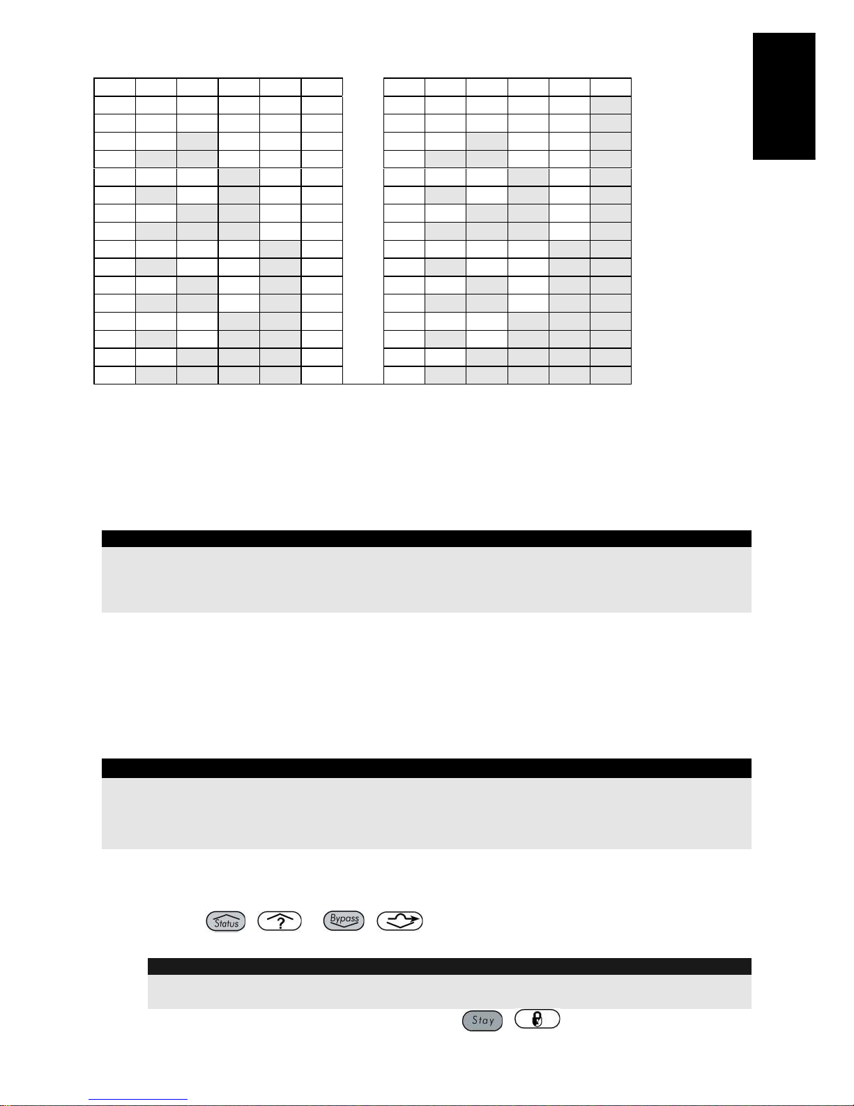
1 - 5
Used to set the detector ID number. (See Table 1) Set the ID number in the
same way as for any other ProSYS accessory (Refer to the ProSYS installation
instruction manual)
6 - 8
Not used
WatchOUT PIR Installation Manual 15
English
WatchOUT ID: DIP Switches 1 - 5
ID 1 2 3 4 5
ID 1 2 3 4
5
01
OFF
OFF
OFF
OFF
OFF
17
OFF
OFF
OFF
OFF
ON
02
ON
OFF
OFF
OFF
OFF
18
ON
OFF
OFF
OFF
ON
03
OFF
ON
OFF
OFF
OFF
19
OFF
ON
OFF
OFF
ON
04
ON
ON
OFF
OFF
OFF
20
ON
ON
OFF
OFF
ON
05
OFF
OFF
ON
OFF
OFF
21
OFF
OFF
ON
OFF
ON
06
ON
OFF
ON
OFF
OFF
22
ON
OFF
ON
OFF
ON
07
OFF
ON
ON
OFF
OFF
23
OFF
ON
ON
OFF
ON
08
ON
ON
ON
OFF
OFF
24
ON
ON
ON
OFF
ON
09
OFF
OFF
OFF
ON
OFF
25
OFF
OFF
OFF
ON
ON
10
ON
OFF
OFF
ON
OFF
26
ON
OFF
OFF
ON
ON
11
OFF
ON
OFF
ON
OFF
27
OFF
ON
OFF
ON
ON
12
ON
ON
OFF
ON
OFF
28
ON
ON
OFF
ON
ON
13
OFF
OFF
ON
ON
OFF
29
OFF
OFF
ON
ON
ON
14
ON
OFF
ON
ON
OFF
30
ON
OFF
ON
ON
ON
15
OFF
ON
ON
ON
OFF
31
OFF
ON
ON
ON
ON
16
ON
ON
ON
ON
OFF
32
ON
ON
ON
ON
ON
ProSYS Programming
The following section describes the additional software programming options, added to the
ProSYS software, that concern the settings of the Without PIR as a BUS detector. Up to 32 BUS
detectors can be added to the system (16 in ProSYS 16) and each of them comes at the expense
of a zone in the system.
It is recommend reading and fully understanding the ProSYS Installation and User Manuals,
before programming the WatchOUT.
Notes:
The WatchOUT is compatible with the ProSYS software Version 4.xx and above.
The WatchOUT can be programmed via the U/D Software from UD Version 1.8 and above.
For maximum operation stability, it is best NOT to exceed a total of 300 meters (1000 feet) of wiring when
connecting the WatchOUT to the BUS
The WatchOUT is part of a new accessory category, BUS zones. Therefore, Adding/Deleting the
WatchOUT is identical to any other accessory with the following exception:
Each BUS Zone Detector should be assigned to a Regular Zone.
Any BUS detector can be assigned to a physical wired zone or to a virtual zone.
Physical zone: Any zone on the ProSYS PCB (zones 1-8) or on a wired zone expander
(ZE08, ZE16).
Virtual zone: Any zone on a BUS zone expander defined as BZ08 or BZ16.
Notes:
Virtual BUS zones are cost effective. They enable to expand your system zones without adding physical zone
expanders.
The virtual BUS zone expander can be used only for BUS zone detectors.
To add a BUS zone expander select type BZ08 or BZ16 when adding a zone expander (Quick key [7][1][2])
To Add / Delete the WatchOUT 312PIR
1. From the installer menu enter the Add/Delete menu: Quick Key [7][1][9][5] for BUS Zones
detectors
2. Use the / or / keys to position the cursor over the Bus Zone
ID number for which you want to assign (or delete) a detector.
Note:
Make sure that the detector's physical ID number is identical to the ID number you select
during programming
3. Place the cursor on the TYPE field and use the / key to select OPR12 for the
WatchOUT 312PIR detector.
16 WatchOUT PIR Installation Manual
4. Press / to confirm.
5. Repeat the process for the other BUS detectors.
Assigning the WatchOUT 312PIR to a Zone
1. From the main installer menu enter Zones: One by One option (Quick key [2][1])
2. Select the zone number that you want to assign the BUS detector.
Note:
If you defined a BUS Zone Expander select a zone number from the virtual zones (defined
by the BUS zone expander).
3. Define Partitions, Groups, Zone Type and Zone Sound.
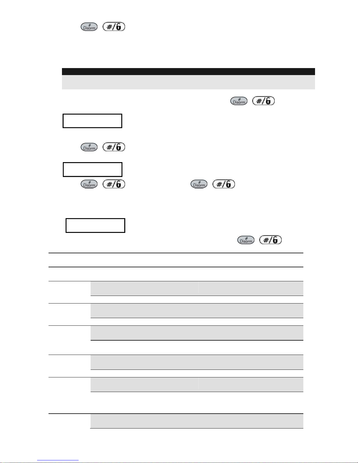
4. In the Termination category select [5] Bus Zone followed by / . The
following display appears:
Z:001 LINK TO:
ID:01 TYPE:OPR12
Z:001 LINK TO:
ID:01 TYPE:OPR12
5. Select the BUS zone number to assign to the programmed zone. The type field will be
updated automatically when selecting the BUS zone.
6. Press / . The loop response category is not applicable to a BUS zone and
the following display appears:
Z:001 RESPONSE:
N/A-BUS ZONE
Z:001 RESPONSE:
N/A-BUS ZONE
7. Press / , assign label and press /
Configuring the WatchOUT 312PIR Parameters
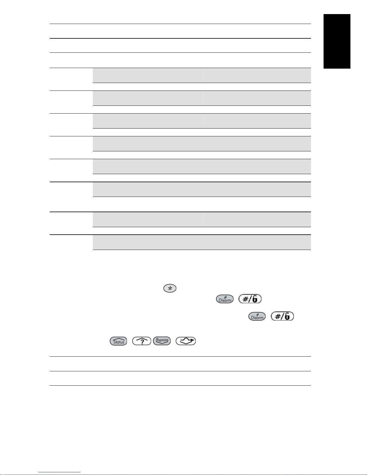
1. To access the WatchOUT settings option press [2][0][3] from the main installer menu.
The following display appears:
B-ZONE PRMS:
ZONE#=001 (M:ZZ)
B-ZONE PRMS:
ZONE#=001 (M:ZZ)
2. Select the zone that the BUS zone was assigned to and press / . You can
now program the WatchOUT parameters as follows:
Zones Miscellaneous: BUS Zone
Quick Keys
Parameter
Default
[2][0][3][zzz]
[1]
LEDS
3 LEDS
Defines the LEDS operation mode
[2][0][3][zzz]
[1][1]
Off
Disables the LEDS operation
[2][0][3][zzz]
[1][2]
Red Only
Only the Red led will operate. This option is highly recommended to avoid
the possibility that the intruder will “Learn” the detector behavior.
[2][0][3][zzz]
[1][3]
3 LEDS
All 3 LEDs will operate
[2][0][3][zzz]
[2]
PIR Sensitivity
Normal
Defines the PIR sensitivity of the detector
[2][0][3][zz]
[2][1]..[4]
Sensitivity Options
WatchOUT PIR Installation Manual 17
English
Zones Miscellaneous: BUS Zone
Quick Keys
Parameter
Default
1) Low
2) Medium
3) Normal
4) High
[2][0][3][zzz]
[3]
Lens Type
Wide Angle
Defines the actual Lens of the detector
[2][0][3][zzz]
[3][1]..[2]
Lens Type Options
1) Wide Angle 2) Barrier / Long Range
[2][0][3][zzz]
[4]
Auxiliary Relay Mode
No
Defines the operation of the Auxiliary relay of the detector
[2][0][3][zzz]
[4][1]
Off
Auxiliary relay is disabled
[2][0][3][zzz]
[4][2]
24 Hours
The Auxiliary Relay will always follow an alarm
[2][0][3][zzz]
[4][3]
Night Only
The auxiliary relay output will follow an alarm condition only during night time.
The time defined by the photocell on the PCB.
[2][0][3][zzz]
[5]
Auxiliary Relay Time
2.2 seconds
Defines the time duration that the auxiliary relay is activated
[2][0][3][zzz]
[5][1]..4]
Auxiliary Relay Time Options
1) 2.2 seconds
2) 2 minutes
3) 4 minutes
4) 8 minutes
Diagnostics
The ProSYS enables you to test parameters that reflect the operation of the detector.
1. From the main user menu press [4] to access the Maintenance menu.
2. Enter the Installer code (or sub-installer) and press / .
3. Press [9] [1] to for the Bus Zones diagnostic menu.
4. Enter the digit of the zone that you want to test and then press / . The
system will perform the diagnostics test and a list of test parameters will appear, as
indicated in the table below.
5. Use the keys / / to view the diagnostics test results
User Menu: 4) Maintenance 9) Diagnostic 1) Bus Zone
Quick Keys
Parameter
[4][9][1][zzz]
Detector Input Voltage: Display the input voltage of the detector.
PIR 1 Level: Displays PIR channel 1 DC level. Range 0.1v - 4v
PIR 1 Noise Level: Displays PIR channel 1 AC level. Range 0VAC
(No noise) - 4VA
PIR 2 Level: Displays PIR channel 1 DC level. Range 0.1v - 4v
PIR 2 Noise Level: Displays PIR channel 2 AC level. Range 0VAC
(No noise) - 4VA

18 Manuale di installazione WatchOUT PIR
INDICE DEI CONTENUTI
Installazione in modalità relé 19
Introduzione 19
Installazione 19
Considerazioni per l’installazione 19
Installazione a parete 21
Installazione piana: 21
Installazione angolare di 45° (installazione a sinistra) 21
Modifica della posizione del tamper antirimozione 22
Cablaggio Morsettiera 22
Predisposizione microinterruttori 23
Regolazione area di copertura 23
Prova di movimento 24
Indicatori LED 25
Microinterruttore Modalità Relé / Bus 25
Installazione dello Snodo Standard 25
Installazione a parete 25
Installazione per tubo elettrico 26
Sostituzione delle Lenti 28
Caratteristiche Tecniche 29
Informazioni per l’ordine 29
Kit Accessori 29
Installazione in modalità BUS 30
Introduzione 30
Cablaggio morsettiera 30
Tamper Antiapertura e Antirimozione 30
Solo Tamper Antiapertura 30
Tamper Antiapertura ad un Ingresso di Zona 30
Predisposizione Microinterruttori 30
Programmazione ProSYS 31
Manuale di installazione WatchOUT PIR 19
Italiano
Installazione in modalità relé
Introduzione
Il rivelatore da esterno ad infrarosso passivo WatchOUT di RISCO, è un dispositivo a
microprocessore che elabora i segnali rilevati tramite due canali all’infrarosso passivo (PIR). Il
WLT312 ha un‟area di copertura regolabile. Il rivelatore può funzionare come rivelatore
tradizionale con uscite a relé collegabili a qualsiasi centrale d’allarme, o come rivelatore
indirizzato via BUS 485 collegato ai sistemi ProSYS di RISCO. Quando viene collegato ai sistemi
ProSYS, il rivelatore può essere programmato e testato sia localmente che in remoto tramite
tastiere LCD ProSYS e/o software di Teleassistenza.
Le istruzioni che seguono descrivono l’installazione e la configurazione del WatchOUT sia in
modalità Relé che via BUS. Per informazioni sul collegamento in modalità BUS ProSYS,
consultare il capitolo il capitolo “Installazione in modalità BUS”.
Installazione
Considerazioni per l’installazione
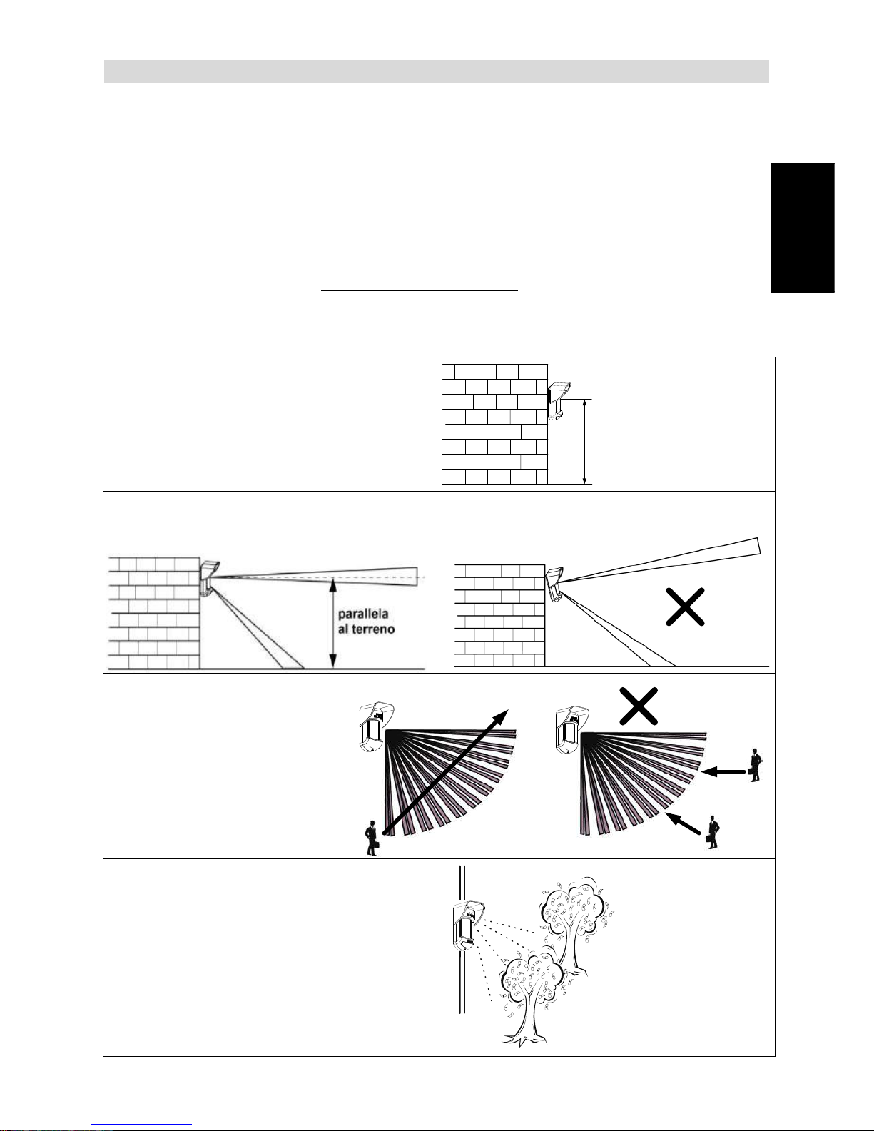
1. Altezza possibile: da 0.8m a 1.2m
Altezza tipica: 1m
Angolo di copertura: 90°
0.8m -1.2m
(2'8" - 3'11")
2. Per ottenere la migliore condizione di funzionamento ed affidabilità, installare il rivelatore
perpendicolare al terreno in modo che la zona di rilevazione superiore sia parallela al terreno.
3. Per una migliore rivelazione
selezionare una posizione
di installazione in modo che
l‟eventuale intruso attraversi
l‟area di copertura.
ü
4. Evitare di direzionare l‟unità verso oggetti in
movimento (alberi ondeggianti, cespugli, ecc.)
20 Manuale di installazione WatchOUT PIR
Installazione del WatchOUT 312PR in situazioni critiche:
Nelle seguenti situazioni variazioni delle radiazioni all‟infrarosso rapide e rilevanti possono far si
che entrambi i canali PIR si attivino contemporaneamente, con conseguenti falsi allarmi.
1. Situazioni in cui oggetti riflettenti di vetro e/o metallo di dimensioni superiori ai 70 cm di
altezza da terra siano nel campo visivo del rivelatore (automobili, cancelli metallici,
saracinesche, muri metallici, finestre, etc.).
2. Situazioni in cui una superficie riflettente a terra con un diametro maggiore di 1m possa
causare un riflesso nelle lenti del rivelatore. Per esempio una piscina, una pozzanghera, la
strada bagnata, asfalto o cemento molto liscio.
Riflesso dell‟acqua
NOTE:
a. Si noti che qualsiasi rivelatore PIR da esterno, per evitare falsi allarmi, richiede una riduzione di portata al
fine di evitare di proteggere superfici riflettenti come auto, oggetti metallici o pozzanghere.
b. Per ottenere una copertura completa a 15m nelle installazioni sopra descritte, si raccomanda di
installare il WatchOUT DT, l’unico rivelatore da esterno con 2 canali PIR e 2 canali a microonde.
c. I rivelatori WatchOUT includono sui sensori PIR dei filtri al silicone di elevata qualità per filtrare le
interferenze causate dalle luci bianche. Questi filtri non bloccano le radiazioni termiche ad infrarossi
necessarie per rilevazione degli intrusi.
Manuale di installazione WatchOUT PIR 21
Italiano
Installazione a parete
Nota:
I numeri di riferimento dei fori a sfondare per
l‟installazione sono marcati sulla base posteriore.
1. Aprire il coperchio frontale del WatchOUT
(Svitare C1, Fig. 1).
2. Sganciare la base interna (svitare I1, Fig. 2).
3. Selezionare l’altezza di installazione come
segue:
Installazione piana:
Aprire i fori a sfondare della base esterna (Fig.3)
B1 - B4: Fori a sfondare per
installazione a parete
T1: Foro a sfondare per il tamper
antirimozione
W2 / W3: Fori a sfondare per il
passaggio cavi
Installazione angolare di 45°
(installazione a sinistra)
a. Aprire i fori a sfondare della base
esterna(Figura 3)
L1, L2: Fori a sfondare per lato
sinistro
T3: Foro a sfondare per tamper lato
sinistro
W5 / W6: Fori a sfondare per il
passaggio cavi
b. Rimuovere la molla del tamper
c. Sostituire la staffa 1 del tamper con la
staffa piana 2 del tamper, fornita.
1
2
d. Inserire la leva B del tamper in T5 e T3
e stringere la vite A (figura 3).
4. Inserire i cavi esterni attraverso la base
esterna W2, W3 (installazione piana) o W5,
W6 (installazione a sinistra)(Fig. 3).
5. Assicurare la base esterna alla parete.
6. Inserire i cavi esterni e i cavi del tamper
attraverso la base interna (Figura 4).
7. Assicurare la base interna a quella esterna
(bloccare I1, Figura 2).
8. Chiudere il coperchio frontale (bloccare C1,
figura 1) dopo aver cablato l’unità e
predisposto i microinterruttori.
9. Effettuare le prove di copertura.
Figura 1
C1
Figura 2
I1
Figura 3
Leva del
Tamper
A
T5
T1
B2
W9
B3
W2
L1
T3
B1
L2
W3
B4
R1
R2
T2
T6
(non visibile)
T4
W5
W6
(non visibile)
W7
W8
B
(non
visibile)
(non
visibile)
Figura 4
Nota:
Per l‟installazione angolare a 45° sul lato destro del rivelatore, usare i riferimenti riportati sulla plastica della
base come da tabella seguente, colonna destra:
Descrizione fori a sfondare
Sinistra
Destra
Fori a sfondare per il fissaggio della base
L1, L2
R1, R2
Fori a sfondare molla tamper
T1,T3
T2,T4
Punto fissaggio vite Tamper
T5
T6
Fori a sfondare per passaggio cavi
W5, W6
W7, W8
22 Manuale di installazione WatchOUT PIR
Modifica della posizione del tamper
antirimozione
Di fabbrica il tamper antirimozione è fissato sul lato
destro della base interna (vista posteriore). Se si
desidera spostarlo nella parte sinistra (vista
posteriore), procedere come segue (Figura 5):
1. Svitare la vite del tamper 1 per rimuoverlo dalla
posizione 7.
2. Assicurarsi che la molla 2 del tamper resti
posizionata sulla base 4 del tamper.
3. Assicurarsi che la staffa 3 del tamper resti tra
2 e 4.
4. Fissare la vite 1 del tamper in 3 sulla
predisposizione 6.
Figura 5
1
3
6
7
5
4
2
Predisposizione
tamper a sinistra
Predisposizione
tamper a destra
Note:
1. Verificare che si senta un "Click" quando la molla del tamper viene spinta verso il muro.
2. Per l‟installazione su palo il tamper può essere spostato nella parte inferiore destra della base interna.
Cablaggio Morsettiera
12Vcc
N.C N.C
+ -
LED
ENABL
ALARM
FREE
N.O COM
GRN
YEL
TAMPER
FREE
N.C
SCHEDA ELETTRONICA - WatchOUT PIR
+,-
12 Vcc
YELLOW
Non Usato. (Solo installazione in modalità BUS)
GREEN
Non Usato. (Solo installazione in modalità BUS)
ALARM
Relè N.C., 24Vcc, 0.1A
TAMPER
Relè N.C., 24Vcc, 0.1A
FREE
Questo morsetto è un morsetto libero per il posizionamento di cavi o resistenze di
fine linea.
LED
ENABLE
Ingresso usato per controllare da remoto i LED quando il microinterruttore 1 è in ON.
LED abilitati: Tensione +12V presente o morsetto non connesso.
LED disabilitati: 0V presente all’ingresso.
N.O
Uscita a relé programmabile per comandare dispositivi ausiliari come ad esempio
telecamere, o luci quando viene rilevato un allarme. Il modo di funzionamento di
questa uscita dipende dalla configurazione dei microinterruttori 4 – 7.
NORMAL IT A'
N.O C OM
N.C
AL L AR ME
N.O C OM
N.C
COM
N.C
SCHEDA ELTTRONICA - WatchOut 312PR - PCB
Manuale di installazione WatchOUT PIR 23
Italiano
Predisposizione microinterruttori
1 2 3 4 5 6 7 8
ON
Default
MIC. 1: Predisposizione LED
ON: LED abilitati
OFF: LED disabilitati
MIC. 2 e 3: Sensibilità rilevazione
Sensibilità
MIC.2
MIC.3
Bassa
Off
Off
Media
Off
On
Normale
(Default)
On
Off
Massima
On
On
DIP 4: Relè uscita ausiliaria
ON: Abilitato
OFF: Disabilitato
MIC. 5: Utilizzato per configurare la modalità di
funzionamento del relè al verificarsi di un
allarme, in funzione della fotocellula che
gestisce il crepuscolare.
ON (Notte): Il relé ausiliario si attiva al
verificarsi di un allarme solo durante la
notte.
OFF (24 Ore): Il relè ausiliario si attiva
sempre al verificarsi di un allarme
MIC. 6-7: Imposta la durata di attivazione del relé
dell’uscita per i dispositivi ausiliari.
Tempo di
Attivazione
Microint. 6
Microint. 7
2.2 secondi
OFF
OFF
2.0 Minuti
OFF
ON
4.0 Minuti
ON
OFF
8.0 Minuti
ON
ON
MIC. 8: LED Rosso /3 LED
ON: Solo LED rosso
OFF: 3 LED
Regolazione area di copertura
Fare scorrere il PIR mobile nella
posizione desiderata, vedere figura 6.
L‟impostazione dell‟area di copertura del
PIR inferiore determina la portata di
rilevazione del sensore.
Il PIR superiore è fisso e la sua area di
copertura è sempre parallela al terreno.
L‟area di copertura inferiore è impostabile
da 2m a 12m a seconda di dove si
posizioni il PIR regolabile. Quindi, la
portata di rilevazione del sensore è
stabilita dal posizionamento del PIR
inferiore. Per generare una condizione di
allarme sia il PIR superiore che quello
inferiore devono essere attivati.
Figura 6
24 Manuale di installazione WatchOUT PIR
Schema di rilevazione (vista laterale)
Portata di rilevazione con
installazione a 1m:
POSIZIONE
MASSIMA
DISTANZA DI
RILEVAZIONE*
A
B
C
D
12m
(40')
7m
(23')
3m
(9'10")
2m
(6'6")
* NOTA:
La portata può variare in funzione delle
condizione climatiche esterne.
Prova di movimento
Dopo 2 minuti dall‟alimentazione del sensore, effettuare una prova di movimento all‟interno
dell‟area protetta e verificare il buon funzionamento e la copertura del rivelatore.
Settare il PIR regolabile per ottenere la portata desiderata.
IMPORTANTE!
Entrambi canali devono essere attivati simultaneamente per generare allarme.
Vedere figura 7 sotto.
NESSUNA RILEVAZIONE
NESSUNA RILEVAZIONE
RILEVAZIONE
Figura 7
Manuale di installazione WatchOUT PIR 25
Italiano
Indicatori LED
LED
Stato
Descrizione
VERDE
Acceso
Indica rilevazione del canale PIR superiore
GIALLO
Acceso
Indica rilevazione del canale PIR inferiore (quello
regolabile)
ROSSO
Acceso
Indica ALLARME (entrambi i PIR hanno rilevato)
Lampeggiante
Indica una anomalia di comunicazione con la
ProSYS (solo modalità BUS)
TUTTI I LED
Lampeggianti (uno dopo l’altro)
Inizializzazione unità all’accensione.
Note:
1. Il microinterruttore 1 va posizionato su ON per abilitare i LED.
2. Solo un LED alla volta può illuminarsi. Per esempio, nel caso di attivazione di entrambi i PIR, o il LED giallo o
quello verde si illumina (il primo che rileva), seguito poi dal LED rosso di allarme.
Microinterruttore Modalità Relé / Bus
Il microinterruttore J-BUS, situato sulla scheda tra i LED rosso e
verde, viene usato per configurare la modalità di funzionamento
del rivelatore.
Modalità
Relè
Modalità
BUS
O
N
O
N
Installazione dello Snodo Standard
Leggere le istruzioni seguenti per installare il rivelatore con questo snodo.
1. Aprire il coperchio frontale (Allentare C1, Figura 1).
2. Sganciare la base interna (Svitare I1, Figura 2).
3. Aprire i fori a sfondare della base esterna (Figura 8, Dettaglio B)
W1: Passaggio cavi
S1,S2: Fori a sfondare per fissare la base esterna allo snodo standard
S3: Predisposizioni per le viti di fissaggio della base esterna
4. Sullo snodo aprire le predisposizioni per il passaggio cavi S2, S7 o S9 (Figura 8, Dettaglio A).
5. Rimuovere il tamper antirimozione dalla base interna (consultare paragrafo "Modifica della
posizione del tamper antirimozione") e collegarlo a S5 (Figura 8, Dettaglio A) sullo snodo standard.
6. Selezionare le opzioni di installazione di seguito descritte:
Nota:
Accertarsi che il marchio UP è presente nella parte frontale superiore dell snodo.
Installazione a parete
a. Inserire il cavo esterno attraverso le predisposizioni S2, S7 o S9 (incluso i cavi del tamper)
ed estrarlo facendolo passare attraverso il passaggio cavi dello snodo (Figura 8, Dettaglio
B).
b. Fissare lo snodo alla parete tramite i fori S1, S3, S6 ed S8.
26 Manuale di installazione WatchOUT PIR
Installazione per tubo elettrico
(utilizzare l’adattatore metallico per tubo elettrico - CSMA, Figura 8, Dettaglio A)
S1
S2
S3
S9
S8
S7 S6
S5
S4
Tamper
(
vedi Dettaglio C
)
Passaggio
cavi dello
snodo
Fori
molla
tamper
Ø 21 mm
Ø 16 mm
CSMA
M1
M2
M3
M4
Dettaglio A Dettaglio B
S1
W1
S2
S3
Linguette
Snodo Standard
Dettaglio C
Figura 8
Nota:
Il CSMA è richiesto quando il cablaggio viene effettuato tramite una tubazione elettrica esterna alla parete.
Questo accessorio va ordinato separatamente con il codice RA300S.
a. Scegliere l’orientamento del CMSA in riferimento al diametro richiesto: 16mm o 21mm.
b. Inserire il tubo elettrico nel CSMA.
c. Fissare il CSMA alla parete tramite i fori M1 e M4.
d. Inserire i cavi esterni e i cavi del tamper che arrivano dal tubo elettrico facendoli passare
tramite il passaggio cavi dello snodo (Figura 8, Dettaglio A).
e. Fissare lo snodo alla parete tramite i fori S1, S3, S6 ed S8.
Nota:
La molla del tamper S5 (Figura 8) deve essere a contatto della parete tramite gli appositi fori M2 o M3 del
CSMA. Assicurarsi di sentire il "Click" dell‟interruttore tamper fissando il dispositivo alla parete.
7. Inserire i cavi del tamper e i cavi esterni che arrivano dallo snodo standard facendoli passare
tramite la predisposizione W1 della base esterna (Figura 8, Dettaglio B).
8. Unire la base esterna allo snodo utilizzando le apposite linguette ad incastro (Figura 9).
Manuale di installazione WatchOUT PIR 27
Italiano
Base esterna
Vite di blocco
orientamento
snodo
(Vedi nota 2)
Vedi Dettaglio A
Viti per la connessione dello
snodo con la base esterna
Dettaglio A
Vite di fissaggio del fermo
posteriore orientamento snodo
(Vedi nota)
Linguette
S1
W1
S2
S3
Base interna
Scheda
elettronica
Figura 9
NOTA:
Per fissare la base del rivelatore allo snodo non usare la vite che blocca il fermo posteriore dello snodo. Questa
vite non va usata poichè serve solo per il blocco dello snodo una volta orientato come desiderato.
9. Fissare la base esterna allo snodo con due viti tramite le predisposizioni S1 e S2 (Figure 9).
10. Inserire nello snodo standard la vite (fornita) di fissaggio ad angolo facendola passare dalla
base esterna attraverso il foro a sfondare S3 (Figura 9).
11. Orientare orizzontalmente e verticalmente lo snodo fino ad
ottenere la posizione desiderata e poi stringere la vite di
blocco orientamento snodo
12. Infilare la base interna nella base esterna ed inserire tutti i
cavi attraverso la base interna.
13. Fissare la base interna a quella esterna (fissare I1, figura 2).
14. Per regolare lo snodo standard quando viene installata la
scheda elettronica (Figura 9):
a. Spostare la gomma nera situata sulla scheda elettronica
sotto al LED rosso (quanto basta per raggiungere la vite di
blocco dello snodo).
b. Utilizzare un cacciavite per svitare la vite di blocco (vedi
Figura 10).
c. Orientare orizzontalmente e verticalmente lo snodo fino ad
ottenere la posizione desiderata.
d. Stringere la vite di blocco orientamento snodo.
Figura 10
NOTA:
Quando i punti marcati delle due parti mobili sono allineati (figura 9), lo snodo standard si trova in posizione 0°.
Ogni “click” verticale da questa posizione corrisponde ad un incremento / decremento di 5°.
15. Chiudere il coperchio frontale (fissare C1, figura 1) e proseguire con la prova di movimento per
verificare l’area di copertura del rivelatore.
NOTA:
La vite deve passare attraverso la base esterna ed essere fissata allo snodo.
 Loading...