

Risco VUpoint RVCM32W Installation Manual
VUpoint
Dome Vandal-Proof P2P
IP Camera
Model: RVCM32W
FR
EN
Installation Guide
IT
ES
Language Page
1
50
25
71
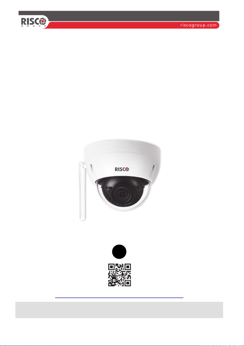
VUpoint
Dome Vandal-Proof P2P
IP Camera
Model: RVCM32W
EN
http://VUpoint-P2P.riscogroup.com/How-to-Install/
Installation Guide

Safety Precautions
These instructions are intended to ensure that the user can use the product correctly to
avoid danger or property loss.
WARNINGS:
Installation or usage of this product that is not in accordance with the intended
use as defined by the supplier and as described in the instructional materials
can result in damage, injury, or death.
Make sure this product is not accessible by children and those for whom
operation of the system is not intended.
All installation and operation should conform to your local electrical safety
codes. The power shall conform to the requirement in the SELV (Safety Extra
Low Voltage) and the Limited power source is rated 12V DC in the IEC60950-1.
If the device is permanently connected to an electrical power supply, then the
connection should include an easily-accessible disconnection device, such as a
circuit breaker. Do not connect the two power supplying sources to the device
at the same time; it may result in device damage!
Do not ever attempt to repair your device by yourself, as doing so could result
in damage, injury or death – always contact your installer / supplier agent for
service.
CAUTIONS:
Make sure the power supply voltage is correct before using the camera.
Do not drop the camera or subject it to physical shock.
Do not touch sensor modules with fingers. If cleaning is necessary, use a clean
cloth with a bit of ethanol and wipe it gently.
Do not aim the camera lens at the strong light such as sun or incandescent
lamp. The strong light can cause fatal damage to the camera.
The sensor may be burned out by a laser beam, so when any laser equipment is
being used, make sure that the surface of the sensor not be exposed to the laser
beam.
Do not place the camera in extremely hot, cold temperatures (the operating
temperature should be between -10°C ~ +50°C).
To avoid heat accumulation, good ventilation is required for a proper operating
environment.
While shipping, the camera should be packed in its original packing.
NOTE: We assume no liability or responsibility for all the fires or electrical shock
caused by improper handling or installation. We are not liable for any problems caused
by unauthorized modification or attempted repair.
2
Introduction
RISCO Group presents VUpoint, a revolutionary live video verification solution
which seamlessly integrates IP Cameras within RISCO’s professional security
systems. Powered by the RISCO Cloud (RISCO Application Server), VUpoint
provides an unprecedented level of security and live video monitoring
capabilities to monitoring stations and end-users alike. The RISCO dome indoor
and outdoor IP Camera is an important part of this solution and
controlled through RISCO’s intuitive Web and Smartphone applications.
Features
Plug & Play installation
1.3 Megapixel
Color HD
Day/Night
IR LED Length 30m
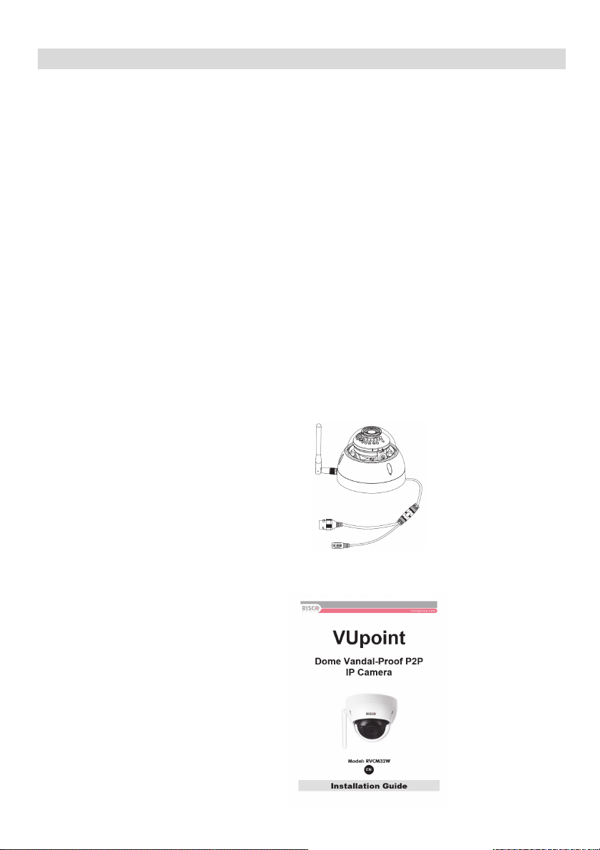
Components and Accessories
is easily
RISCO IP camera and
mounting bracket:
Installation guide:
3
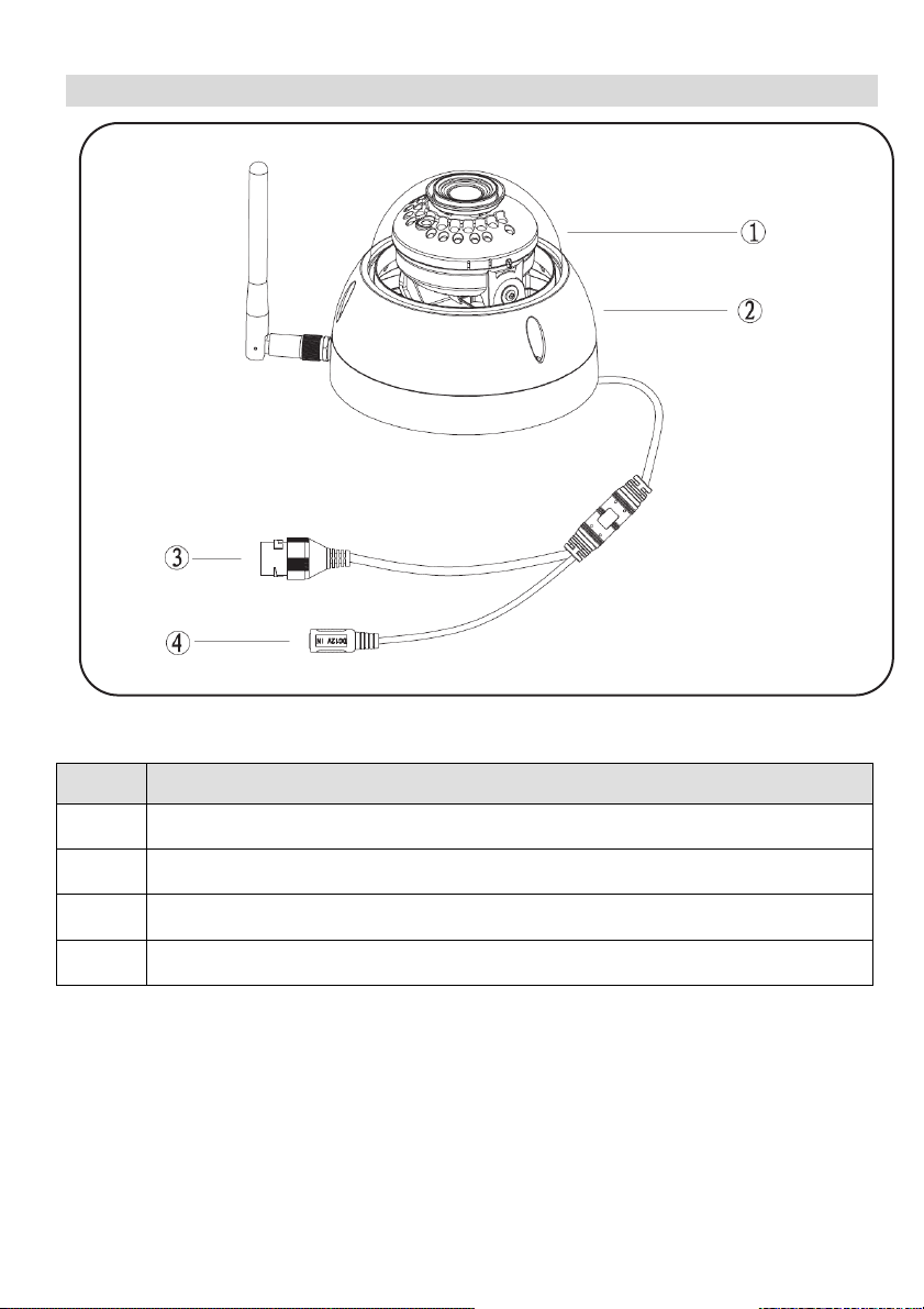
IP Camera Components and Dimensions
Figure 1 External View and Ports
Label Name
1
2
3
4
Dome cover
Dome enclosure
Network port
Power port
4
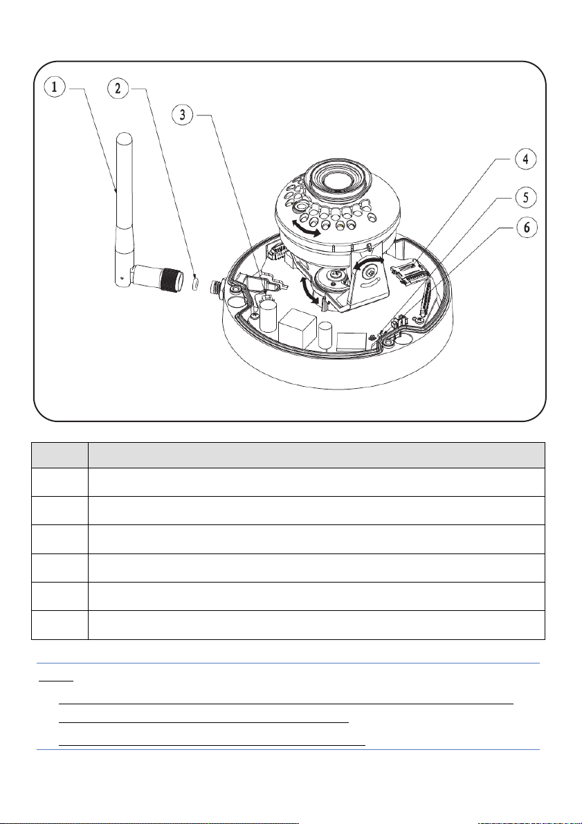
Figure 2 IP Camera Components
Label Name
1
2
3
4
5
6
Wireless antenna
Waterproof ring
Reset/ WPS (Wi-Fi Protected Setup) button
Micro SD card slot
Indicator light 1
Indicator light 2
Note:
For reset (used to return the camera settings to factory default mode), long
press for 15 seconds and then the light turns off
For WPS (Wi-Fi Protected Setup), one quick press.
5
Indication Status
Red light normally on
Booting
Green light slow
flashing
Green light quick
flashing
Green light normally
on
Red and green lights
flash alternately
Red light slow flashing
Red light quick
flashing
IP Camera is not connected to the RISCO Cloud. Please check
for internet connection and try to connect again by rebooting
the IP Camera.
WiFi smart config in progress, including WPS (WiFi Protected
Setup), management frame and etc.
IP Camera is successfully connected to the RISCO Cloud.
Device upgrade
Network connection failure or disconnection after network
connection success.
Device malfunction, fail to boot up; alarm or SD card
malfunction
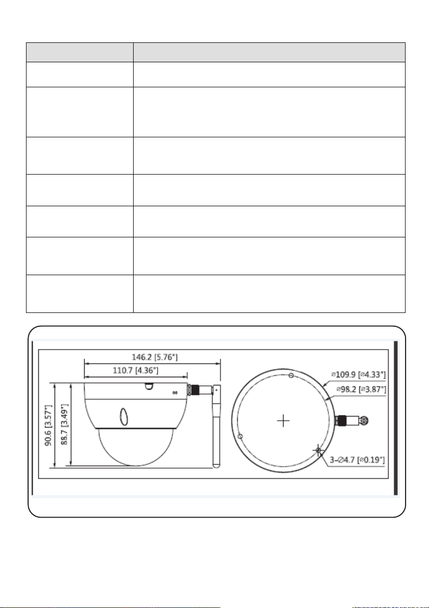
Figure 3 IP Camera Dimensions
6
IP Camera Installation
After reading the installation instructions and before installing your IP camera,
prepare a plan for mounting the IP camera at your protected site. Correct
placement of your IP camera is crucial for optimal security-monitoring
performance. First, determine which areas need to be protected and then map
out the most optimal areas for installing your IP camera.
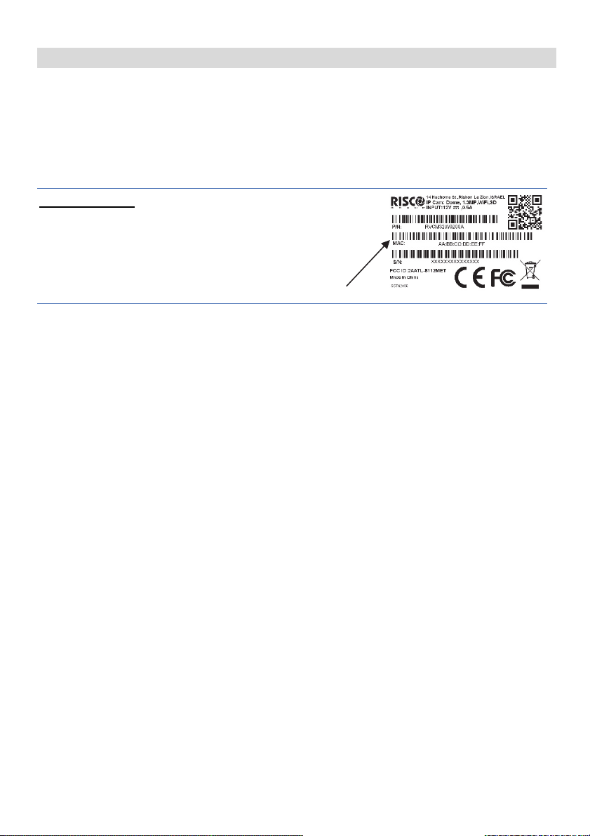
IMPORTANT! – Please make a record of the MAC
address located on the box or on the back cover of
the IP camera before installation. You may need it
during the network connection stage.
MAC address
7
Mounting the IP Camera
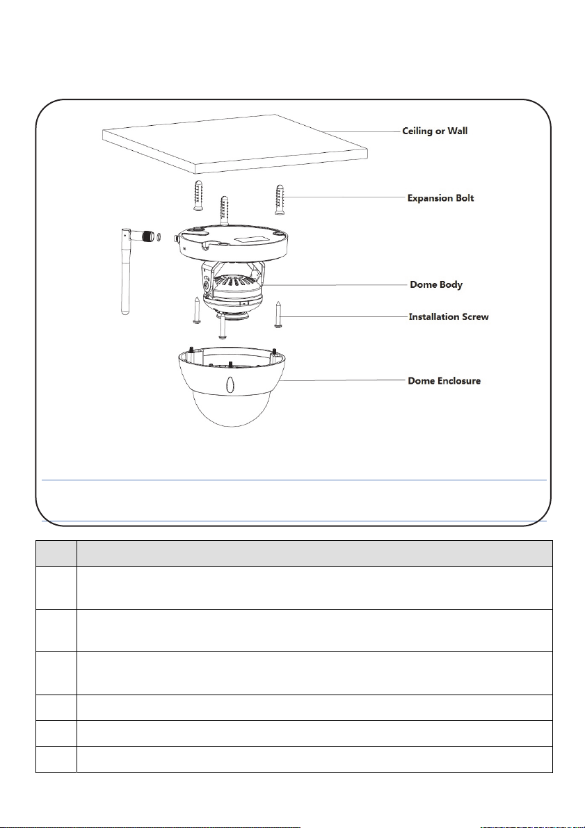
Figure 4 Mounting
IMPORTANT- Please make sure the installation surface can support at least 3
times the weight of the camera and the bracket.
Step Description
1
Use the supplied hex wrench to open the dome enclosure by releasing the three
inner hex screws.
2
Place the installation positioning template on the installation surface such as
ceiling or wall.
3
Make holes in the installation surface according to the installation positioning
template.
4
Insert the three expansion bolts into the holes.
5
Position the IP camera base over the holes
6
Use the screws from the accessories bag to secure the IP camera firmly.
8
Step Description
If you run the cable from the top of the installation surface, make an exit hole
on the installation surface according to the installation positioning template.
If you run the cable from the side of the cable channel, it must go through the
U-shaped channel on the dome support. Take out the cable from the side of the
exit hole located on the support.
7
Adjust the device installation support to the proper position and then run the cable
through the exit hole located on the installation surface.
8
Align the TOP mark on the device installation support with that of the installation
template.
9
Align the three screw holes in the device support with the three plastic expansion
bolt holes in the installation template.
10
Firmly affix the three self-tapping screws to the three plastic expansion bolts.
11
Secure the dome body to the installation surface.
12
Hold both sides of the base of the rotation bracket, rotate horizontally along the
axis and adjust the lens in the horizontal direction to the designated position.
13
Hold the LED cover and rotate it vertically while adjusting the lens in the vertical
direction to the designated position.
If too tight to adjust, first loosen the fixed screws on both sides of the bracket (do not
remove the fixed screws), then adjust the lens and tighten again the fixed screws.
14
While holding the LED cover, rotate it along the axis and adjust the lens image to
the correct surveillance position.
Range of lens:
vertical (0°~+64°)
horizontal (0°~+355°)
image rotation direction (0°~+355°)
NOTE – When rotation is at 64° in the vertical direction, please pay attention to the
image rotation direction in order to prevent blockage of the IR light by the outer
cover, as this can negatively influence the IR effect.
9

Powering-up the IP Camera
1. Connect power to the Power port on the IP camera.
2. Connect power to an electrical outlet. When the IP camera boots up, the
GREEN power indicator light flashes.
Connecting the IP Camera to the Network
The IP camera supports several network connection options including LAN and
Wireless.
Connecting to a LAN Network
Connecting the IP camera to a network using the LAN (Local Area Network)
enables easy connection and setup with compatible APs (Access Points), e.g.
gateway or router.
1. Connect the incoming network cable to the Network port on the IP camera.
2. The GREEN network indicator lights to indicate that your IP camera is now
Connecting to a Wireless Network using WPS
Connecting the IP camera to a wireless network using WPS (Wi-Fi Protected
Setup) requires that the router supports WPS functionality.
connected to the network. Continue as explained in Defining IP Camera
Settings.
NOTE – Some routers have a virtual button on their management software.
(Refer to the router’s documentation for details about using its WPS functions).
1. Once the power cord is connected, wait for slow flashing GREEN network
indicator.
2. Momentarily press the WPS button on the IP camera and hold down the
WPS button on the router for 2 seconds. The GREEN network indicator light
indicates that your IP camera is now connected to the network. Continue as
explained in Defining IP Camera Settings.
10

Connecting to a Wireless Network using the RISCO Cloud
Connecting the IP camera to a wireless network using the RISCO Cloud (RISCO
Application Server) requires that you first connect the IP camera to the router via
the LAN and then, from the RISCO Cloud Installer Application, define the IP
camera settings and establish a wireless connection. Once a wireless connection
has been established the IP camera can then be disconnected from the router and
installed/mounted.
1. Connect the incoming network cable to the Network port on the IP camera.
2. The GREEN network indicator lights to indicate that your IP camera is now
connected to the network. Continue as explained in Defining IP Camera
Settings.
NOTE – Before disconnecting you must configure the wireless network through
the RISCO Cloud.
3. Once a wireless connection has been established, you may disconnect the IP
Camera from the router and install/mount it anywhere within the monitored
area.
11
IP Cameras and the RISCO Cloud Installer Application
The RISCO Cloud Installer Application provides an interface to your control
panel from a local or remote PC via the Web. This enables you to add IP cameras
and define camera and event alarm trigger settings.
IMPORTANT – A control panel must first be defined in RISCO Cloud in order
to accept IP cameras and define camera settings (Refer to the RISCO Cloud
Installer Application Manual)
Defining IP Camera Settings
Once you have connected the IP camera to the network (refer to, Connecting the
IP Camera to the Network) you can define the camera settings.
To define IP camera settings:
1. Log into the Installer Administration application using the Web page address
supplied by your service provider and enter your user name and password.
NOTE – It is recommended to use Google Chrome or Mozilla Firefox to log into
the Installer Administration application.
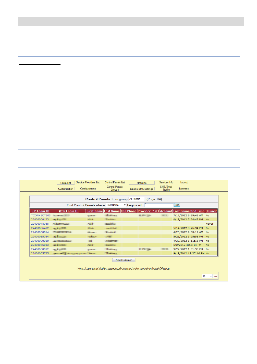
2. Select the Control Panels List link. The Control Panels List page is displayed.
Figure 5 Control Panels List Page
3. From the Control Panels List page, select the Control Panel you wish to view.
The Control Panels Update page is displayed.
12
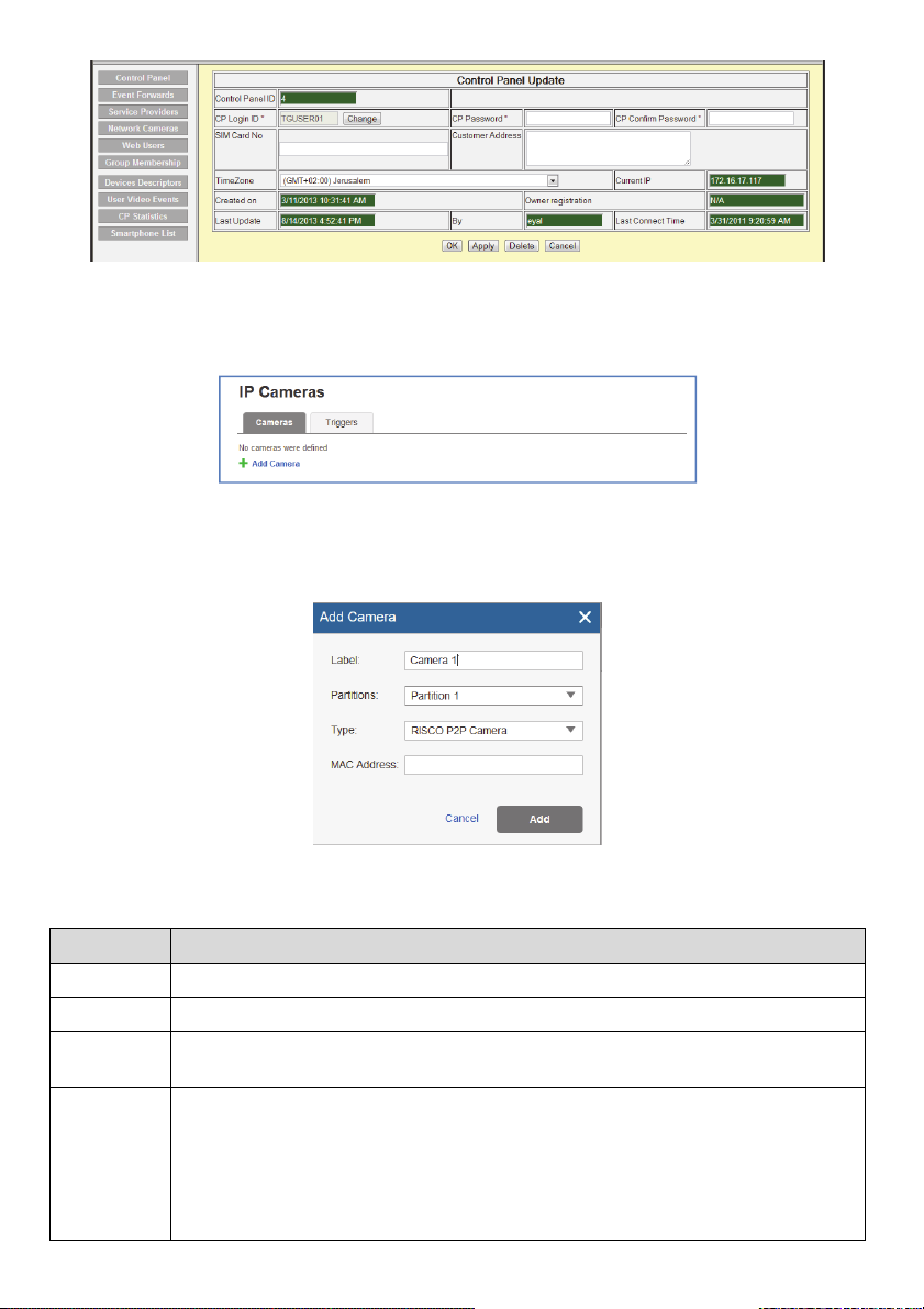
Figure 6 Control Panel Update Page
4. Click the Network Cameras link in the left-hand column; the IP Camera List
page is displayed.
Figure 7 IP Cameras List
5. Click Add Camera; the Add Camera dialog box is displayed.
6. Select the RISCO P2P Camera type.
Figure 8 Add Camera
7. Define the following fields in the Add Camera dialog box.
Field Description
Label
Partitions
Type
MAC
Address
Enter a name for the camera
Select the partition(s) from the list of defined partitions
Choose the RISCO P2P Camera type (for ONVIF or Generic camera type
settings, refer to the RISCO Cloud Installer Application Manual)
Enter the MAC address into this field. The MAC address (media access
control address) is the unique identifier assigned to the IP camera for
communications on the physical network.
NOTE: The MAC address is case sensitive and should be entered exactly as
it is shown on the box or on the back cover of the IP camera, e.g.
AA:BB:CC:DD:EE:FF
13
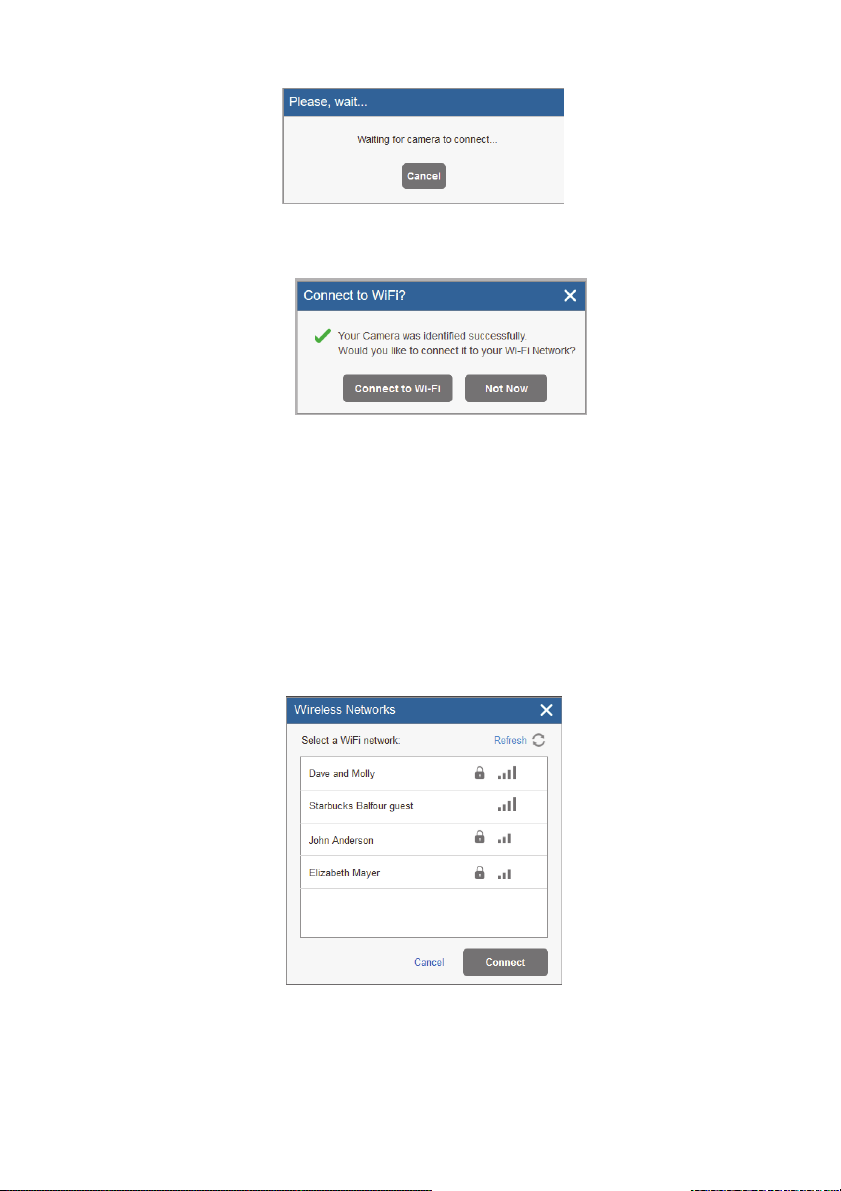
8. Click Add; the following message is displayed.
Figure 9 Waiting for camera to connect message
If the “Connect to WiFi” message is displayed, go straight to step 8.
Figure 10 Connect to WiFi message
9. Select one of the following options:
Connect to Wi-Fi – to establish a wireless network connection (go to step 9 to
connect the IP camera to the wireless network).
Not Now – to maintain IP Camera connection using a LAN network
connection (skip the wireless network connection steps 10, 11 and 12 and
connect the IP camera to the LAN network).
10. If you selected the “Connect to Wi-Fi” option, a list of available wireless
networks is displayed.
Figure 11 List of available wireless networks
11. Select a wireless network from the available list and click Connect.
14
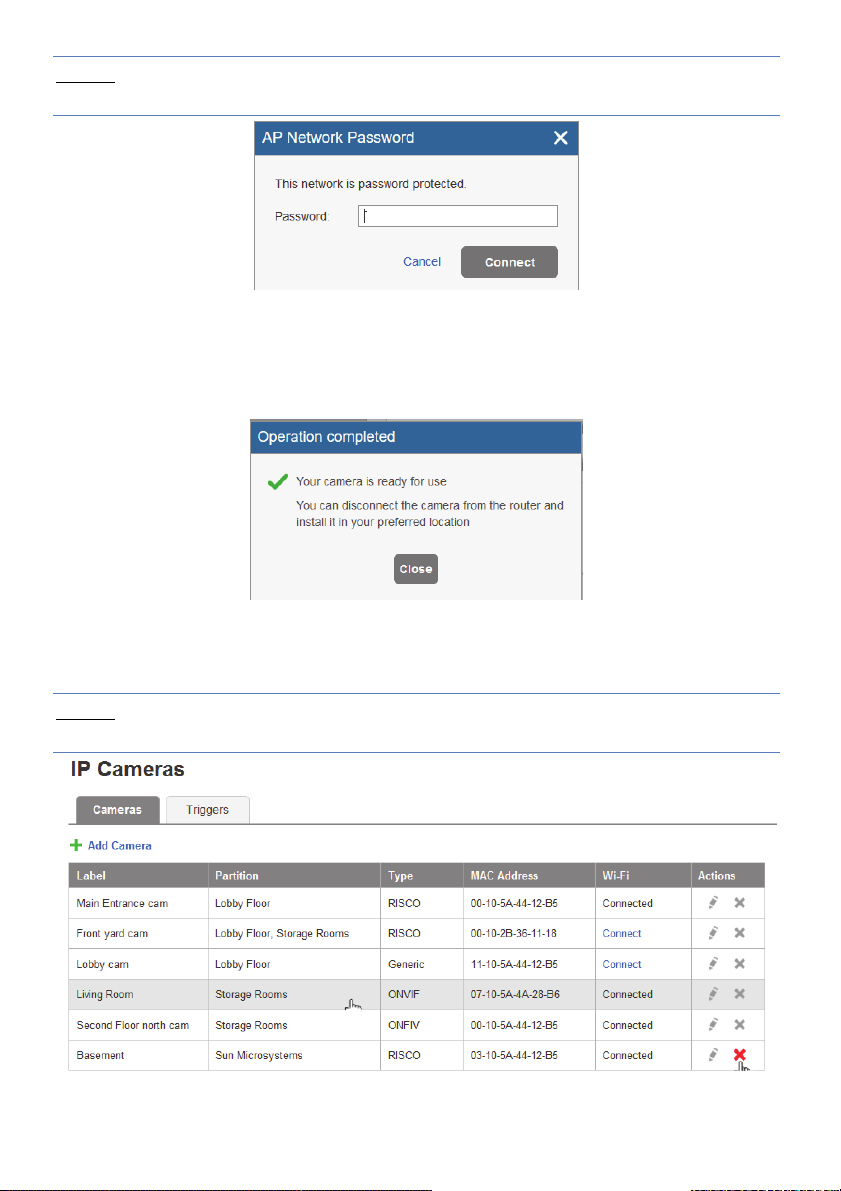
NOTE – If your network is password protected, a password must be entered into
the displayed password screen.
Figure 12 AP Network Password
12. Click Connect to establish the wireless connection (Refer to Connecting to a
Wireless Network using the RISCO Cloud); the following success message is
displayed.
Figure 13 Operation Completed
13. Once the “camera is ready for use” message is displayed, click Close. The
defined IP camera is displayed in the IP Cameras page.
NOTE – Once a wireless connection has been established, don’t forget to
disconnect the IP camera Ethernet cable from the router.
Figure 14 IP Camera List
15

NOTE – You also have the option to edit or delete the selected IP camera.
Click the FW Action button below to check if the firmware is up-to-date.
Figure 15 Firmware Update
The newer Firmware version will be displayed in the screen that opens, if applicable.
Figure 16 Newer Firmware Version
Defining Camera Trigger Settings
Any event from the following list can be defined to trigger an alarm.
Partition Events
Fire Alarm Panic Alarm Medical Alarm Alarm
Full Arm Part Arm Disarmed Duress
Tamper 24 HR-X Alarm Water Alarm Gas Alarm
Environ. Alarm No Motion Alarm Exit Alarm Low Temperature
Detector Events
Alarm Zone Bypassed Zone Un-bypassed Zone Tamper
16
To define camera trigger settings:
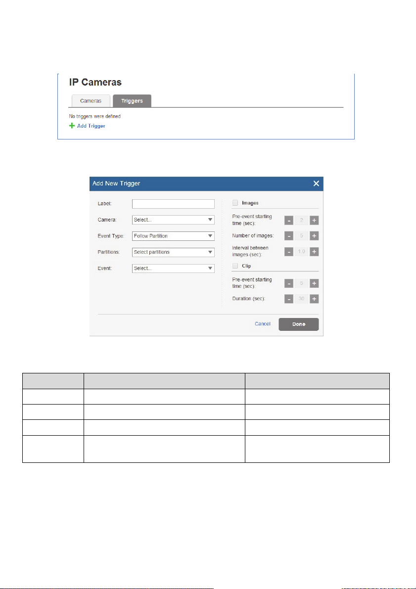
1. From the Control Panel Cameras page, click the Triggers tab, the Camera
Triggers List page is displayed.
Figure 17 Camera Triggers List
2. Click Add Trigger; the Add Triggers dialog box appears.
Figure 18 Add Trigger
3. Define the following fields in the Add Trigger dialog box:
Field Description Event Type
Label
Camera
Event Type
Event
Enter a name for the camera trigger Partition and Detector events
Choose a camera from the list Partition and Detector events
Choose an event type from the list Partition and Detector events
Choose the event from the list, e.g.
alarm, duress, etc.
17
Partition and Detector events
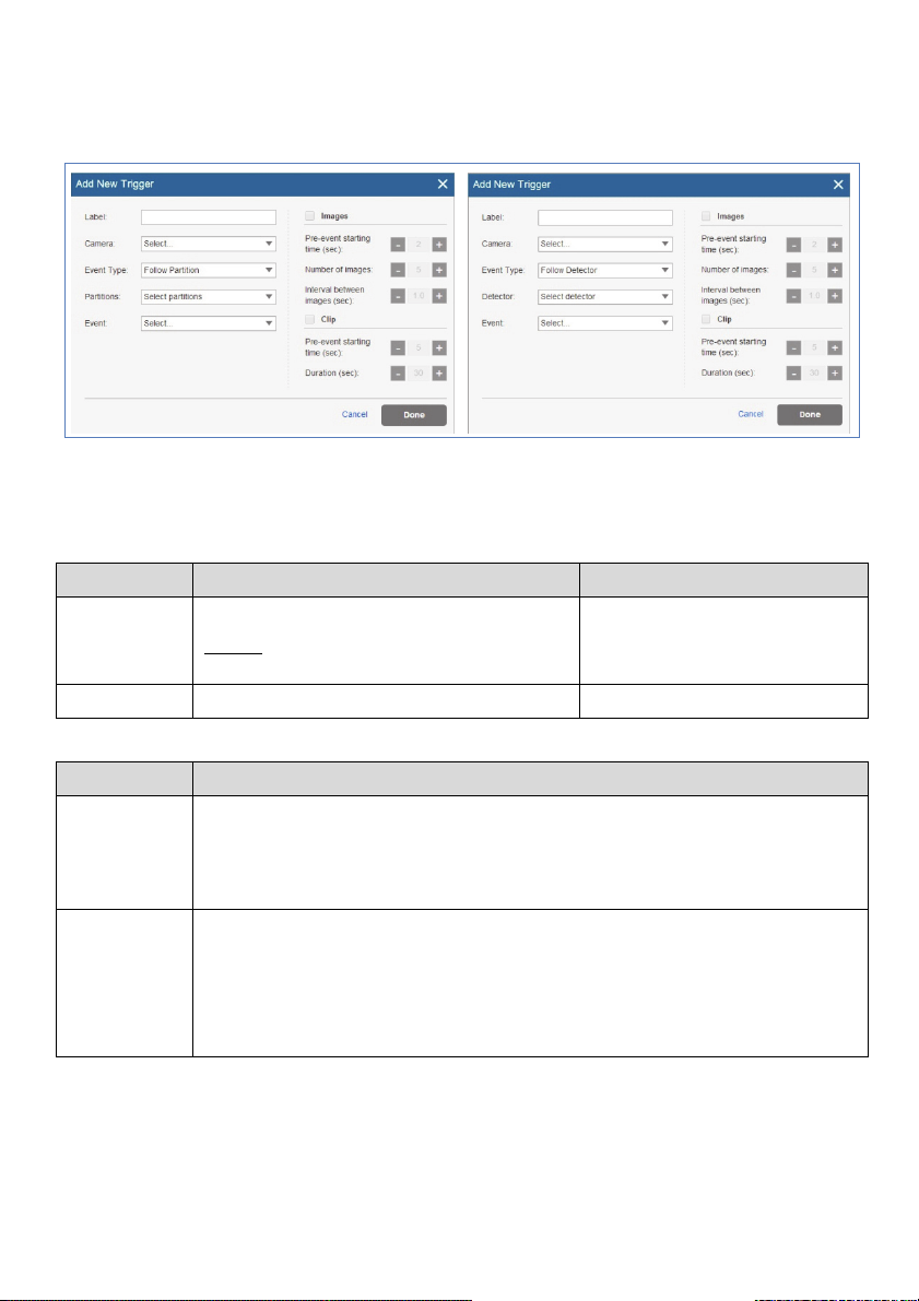
Additional fields are displayed in the Add Trigger dialog box according to the
event type that you selected (see examples below for Partition and Detector event
types).
Figure 19 Add Partition Event Trigger Figure 20 Add Detector Event Trigger
4. Define the following fields in the Add Trigger dialog box according to the
event type that you selected.
Field Description Event Type
Partition(s)
Detectors
Select the partition(s) from the list.
NOTE – Only partitions associated with
the camera are displayed.
Select the detector from the list Detector events only
Partition events only
5. Define the following image (still) and clip (video) definitions:
Field Description
Images
(still)
Clips
(video)
Pre-event starting time (sec) – time, before the actual event occurred, to
start displaying still images.
Number of images – number of still images to display.
Interval between images (sec) – time required between each still image.
Pre-event starting time (sec) – time, before the actual event occurred, to
start displaying video clip.
Duration (sec) – total duration of the video clip
NOTE – These fields are currently locked and the default parameters
cannot be changed.
NOTE: To be able to record video clips, make sure to insert an SD Card and then
power down/up the camera.
18
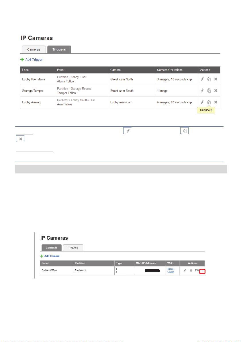
6. Once finished, click Done. The defined camera trigger is displayed in the
Camera Triggers List page.
Figure 21 Camera Triggers List
NOTE – You also have the options to edit , create a duplicate , or to delete
the selected camera trigger.
IMPORTANT – No two camera triggers can be defined as identical. If a camera
trigger is duplicated, the event, camera or both definitions must be changed.
Advanced Settings
For security reasons, measures have been taken to minimize the risks of hacking by
restricting access to the IP Camera. However, in some cases, it is necessary to modify the
default IP Camera settings according to requirement in the field. This is performed by
experienced installers with special permission to access the IP Camera settings.
To Access the IP Camera Settings
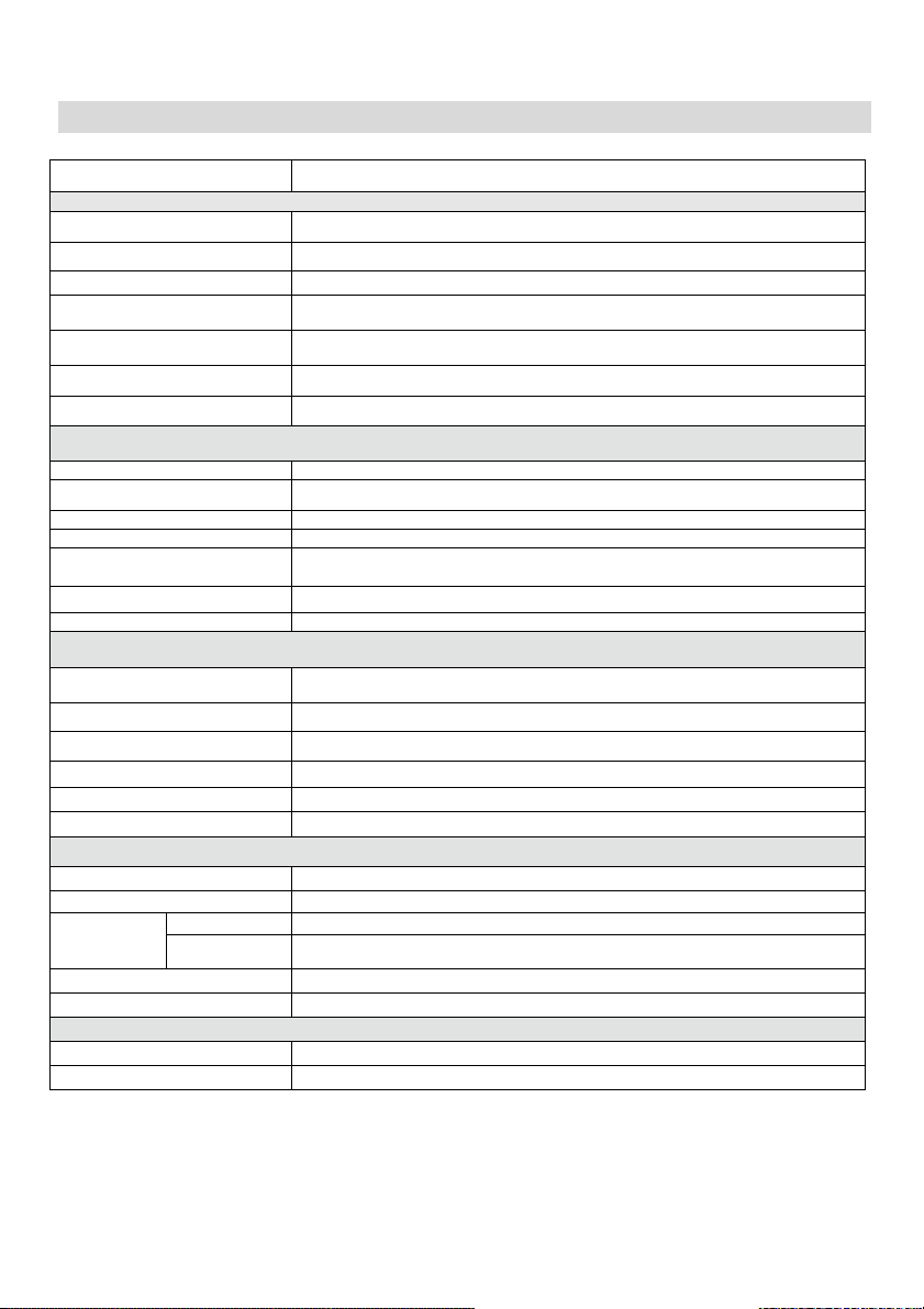
1. Click the “…” button below to enable the UI/CGI option.
Figure 22 IP Cameras Settings
19

The following screen appears.
Figure 23 Enable UI/CGI Option
2. Select the UI/CGI checkbox.
3. Click Save.
The installer is now provided with access to the Web interface of the IP Camera
for a duration of one hour. Open an Internet browser and enter the IP address of
the camera. By Default, the Username and Password for the IP Camera login is
“admin” and “_AdmiN_+ IP Camera MAC address” (for example,
AdmiN_AABBCCDDEEFF).
NOTE: After one hour, access to the camera will be disabled.
Connecting to a Local Network Video Recorder (NVR)
The installer can connect the IP Camera to a local NVR. The installer must
determine the IP Address of the IP Camera and configure it as an ONVIF camera
in the NVR. In addition, the installer must enter the IP Camera’s credentials.
By Default, the Username and Password for the IP Camera login is “admin” and
“AdmiN_+ IP Camera MAC address” (for example,
_AdmiN_AABBCCDDEEFF). The same credentials are used for the ONVIF
camera.
The installer can now also access the live stream from the IP Camera.
NOTE: Changes performed on the default IP Camera settings are at the responsibility of
the installer.
20
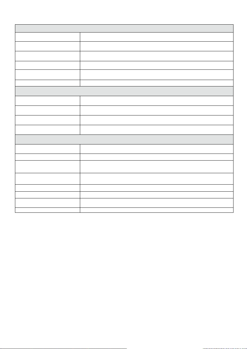
Product Specification
Model RVCM32W0200A
Camera
Image Sensor 1/3” 1.3Megapixel progressive scan CMOS
Effective Pixels
Scanning System Progressive
Electronic Shutter Speed Auto/Manual, 1/3(4)~1/100000s
Min. Illumination
S/N Ratio
Video Output
Camera Features
Max. IR LEDs Length 30m
Day/Night Auto(ICR)/Color/B/W
Backlight Compensation BLC / HLC / DWDR
White Balance Auto/Manual
Gain Control Auto/Manual
Noise Reduction 3D
Privacy Masking Up to 4 areas
Lens
Focal Length 3.6mm
Max Aperture F2.0(F2.0)
Focus Control Manual
Angle of View H: 72°(92°)
Lens Type Fixed lens
Mount Type Board-in Type
Video
Compression H.264/H.264H/H.264B/MJPEG
Resolution
Frame Rate
Bit Rate
Corridor Mode
Audio
Compression
Interface
Main Stream
Sub Stream
1280(H) x960(V)
0. 1Lux/F2.0(Color), 0Lux/F2.0(IR on)
More than 50dB
N/A
1.3MP(1280×960)/720P(1280×720)/ VGA(640×480)/QVGA(320×240)
1.3MP/720P(1 ~ 25/30fps)
VGA/QVGA(1 ~ 25/30fps)
H.264: 32kbps~8192kbps
Support
N/A
N/A
21
Network
Ethernet
Wi-Fi
Protocol
Compatibility ONVIF, CGI
Max. User Access 20 users
Smart Phone iPhone, iPad, Android
Auxiliary Interface
Memory Slot Micro SD card, up to 128GB
RS485 N/A
Alarm N/A
PIR Sensor Range N/A
General
Power Supply DC12V
Power Consumption <4.6W(IR on)
Frequency and Power 2412 – 2462 MHz, 0.0215 W
Working Environment -30°C~+50°C, Less than 95% RH
Ingress Protection IP67
Vandal Resistance IK10
Dimensions Φ110mm×81mm
Weight 0.55kg with package
RJ-45 (10/100Base-T)
Wi-Fi(IEEE802.11b/g/n)
50m(open field)
P2P, IPv4/IPv6, HTTP, HTTPS, TCP/IP, UDP, UPnP, ICMP, IGMP, RTSP, RTP,
SMTP, NTP, DHCP, DNS, PPPOE, DDNS, FTP, IP Filter, QoS
2422 – 2452 MHz, 0.0095 W
22

NOTES
23

NOTES
24
VUpoint
Caméra IP P2P Dôme Anti-Vandale
Modèle : RVCM32W
FR
http://VUpoint-P2P.riscogroup.com/How-to-Install/
Guide d'installation

Consignes de sécurité
Ces instructions sont destinées à faire en sorte que l'utilisateur puisse utiliser le produit
correctement pour éviter tout danger ou toute perte matérielle.
MISES EN GARDE :
Toute installation ou utilisation de ce produit sans respecter l'usage prévu tel
que défini par le fournisseur et comme décrit dans les matériels pédagogiques
peut entraîner des dommages, des blessures ou la mort.
Tenez ce produit hors de portée des enfants et des personnes auxquelles il n'est
pas destiné.
L'installation et l'utilisation doivent être conformes aux codes de sécurité
électrique locaux. L’alimentation doit être conforme aux dispositions de la
SELV (Safety Extra Low Voltage) ; la source d'alimentation limitée doit être de
12 V CC conformément à la norme IEC60950-1.
Si ce produit est raccordé de façon permanente à une source d’alimentation
électrique, un dispositif de déconnexion facilement accessible, tel qu’un
disjoncteur, doit être mis en place. Veillez à ne pas connecter simultanément les
deux sources d’alimentation à l'appareil, car cela risque de l’endommager.
Ne tentez jamais de réparer vous-même cet appareil, car cela risque de
provoquer des dommages matériels, des blessures, voire la mort. Veillez à
toujours contacter votre installateur/fournisseur pour toute maintenance.
AVERTISSEMENTS :
Assurez-vous que la tension d'alimentation est correcte avant d'utiliser la
caméra.
Veillez à ne pas laisser tomber la caméra ou à la soumettre à des chocs
physiques.
Ne touchez pas les modules capteurs avec les doigts. Si un nettoyage est
nécessaire, utilisez un chiffon propre avec un peu d'éthanol et essuyez
délicatement.
N'exposez pas l'objectif de la caméra à une source lumineuse puissante,
notamment à la lumière du soleil ou à une lampe à incandescence. Ces sources
lumineuses risquent de provoquer des dommages matériels irréversibles.
Un faisceau laser peut brûler le capteur ; par conséquent, lors de l'utilisation
d'un appareil laser, vérifiez que la surface du capteur n'est pas exposée au
faisceau laser.
N'exposez pas la caméra à des températures extrêmes froides ou chaudes (la
température de fonctionnement doit être comprise entre -10 °C et +50 °C).
Pour éviter l'accumulation de chaleur et assurer un environnement d'utilisation
correct, une bonne ventilation est nécessaire.
Lors du transport, la caméra doit être placée dans son emballage d'origine.
26

NOTE : nous déclinons toute responsabilité en cas d'incendie ou de choc électrique dû à
une manipulation et/ou une installation incorrectes. Nous ne pouvons être tenus pour
responsables en cas de problèmes causés par une modification ou une tentative de
réparation non autorisées.
27
Introduction
RISCO Group présente VUpoint, une solution de vérification vidéo en direct
révolutionnaire qui intègre de façon transparente les caméras IP au sein de nos
systèmes de sécurité professionnels Géré par RISCO Cloud, VUPoint offre un
niveau de sécurité sans précédent en offrant la surveillance vidéo en direct aux
stations de télésurveillance et aux utilisateurs commerciaux/résidentiels. La
Caméra IP Dôme Intérieure et Extérieure de RISCO est une partie importante de
cette solution et est facilement contrôlé par les applications Smartphone et Web
intuitives de RISCO.
Caractéristiques
Installation Plug & Play
1,3 Mégapixel
Couleur HD
Modes Jour/Nuit
LED IR d'une portée de 30 m
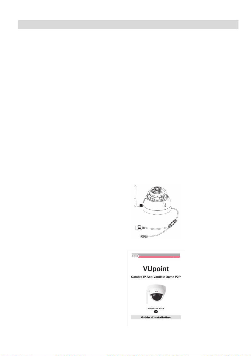
Composants et accessoires
Caméra IP RISCO et
support de montage :
Guide d'installation :
28
 Loading...