

Risco ShockTec Plus Grade 3 Installation Instructions Manual
Introduction
ShockTec Plus Grade 3 is a digital shock detector with magnetic
contact for internal use that provides reliable 24-hour perimeter
protection. A break-in is detected as soon as the intruder attempts to
force, smash, drill or even saw through the protected window, door,
wall or roof. ShockTec employs an advanced digital microprocessor to
analyze the vibration signal received from the piezo electric sensor.
A unique feature of ShockTec Plus Grade 3 is digital sampling of the
signal simultaneously in two separate channels, each channel
amplified at a different gain. This provides an extremely wide dynamic
range of the sampled signal, enabling precise measurement and
analysis of the shock signal.
The ShockTec Plus Grade 3 has a magnetic reed switch for double
protection of shock plus opening of windows or doors. Any attempt to
defeat the detector by using large magnets, as defined by
EN-50131-2-6 Security Grade 3 requirements, will cause a tamper
condition.
Main Features
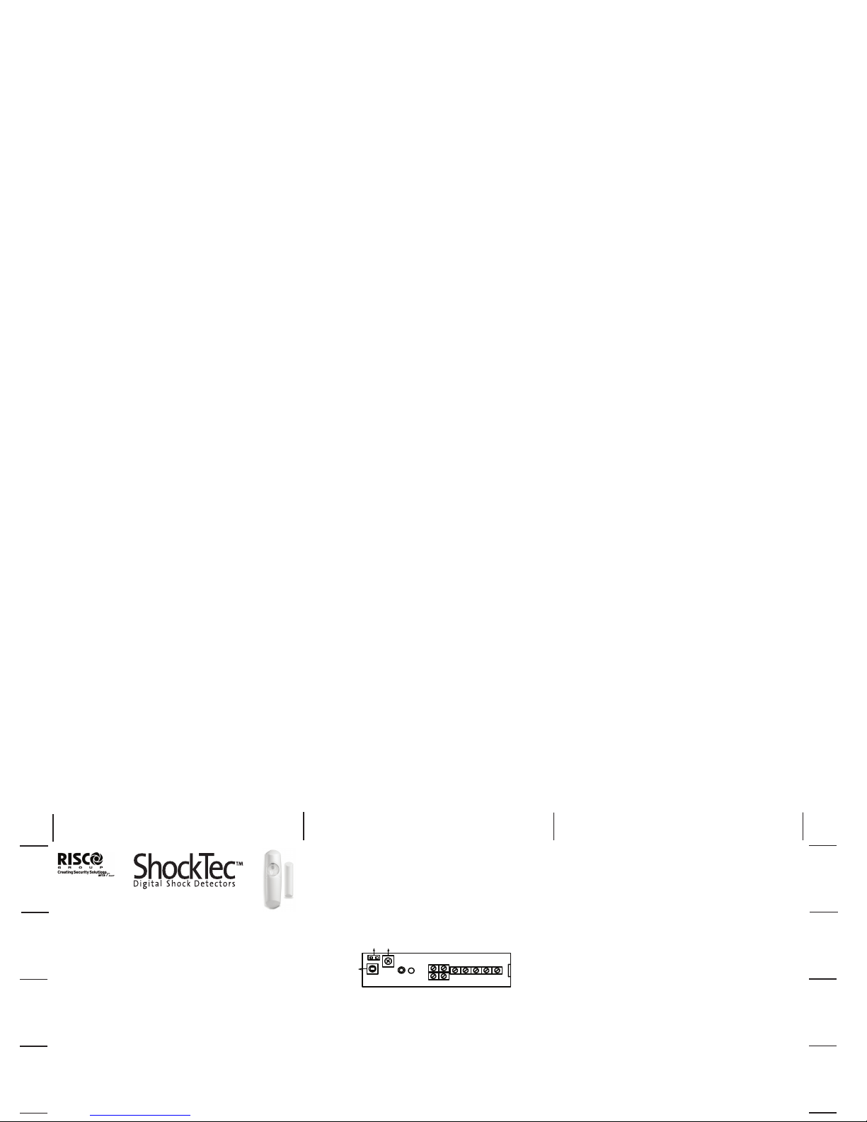
Terminal Wiring
-12V+ 12V power connection, reverse polarity protected
ALARM NC Alarm output contact
LED Connection for +12V remote latch control signal
TAMPER NC Anti-Tamper and Anti-Magnet contact
REED SWITCH NC Door alarm contact switch
Figure 1: Terminal Connections Diagram
Modes of LED Indication
The LED of the ShockTec Plus G3 has three operational modes. The
NC alarm contacts are non-latching in all modes of operation. On alarm
activation, the alarm contacts open the circuit for 2.5 seconds.
1. Normal Operational Mode
No voltage is applied to the LED Terminal. The LED illuminates while
the ALARM contact is open in response to an input signal.
• GREEN: Indicates an alarm condition.
• RED: Under -Sensitive indication.
• ORANGE: Over-Sensitive indication.
Installation Procedure
1 Select the intended position for installation, ensuring the surface
is clean and clear of any irregularities. Refer to Table 1 for
details about detection ranges for the different surface types.
NOTE: When installing the Magnetic Contact, refer to the
Considerations for Magnet Installation section.
2 Remove the cover of the detector by unscrewing the lens using
the special key supplied and then unscrewing the single captive
screw, until the cover is easily removed from the base.
3 Carefully lift the printed circuit board from the base by releasing
the restraining catch.
4 Place the base on the mounting position and mark the desired
fixing holes.
5 If rear cable entry is required, thread the cables through the rear
of the base by removing the appropriate knockout.
6 Fix the base in position.
7 Carefully clip the printed circuit onto the base.
8 If side cable entry is required, draw the cable through the rubber
grommet and complete the electrical connection.
9 Set the detector’s sensitivity as follows:
NOTE: The LED terminal should not be connected to 12V
supply during the sensitivity test.
i With the unit set for normal operation, use a suitable
instrument to bang or tap the protected area.
ii If the sensitivity needs adjustment, use a screwdriver to
adjust the trimmer (turn the trimmer control clockwise to
ShockTec Plus Grade 3
Installation Instructions
HIGH / LOW
SENSITIVITY
SENSITIVITY
ADJUSTMENT
TAMPER
MIN MAX
LED
REED
SWITCH
TAMPER
LED ALARM -12V +
J1
Cut
Fold
Fold
Fold
Fold
Cut
Fold
Fold
Fold
Fold
Cut
Fold
Fold
Cut
Maximum humidity 95% non-condensing
Sensitivity settings Dual stage potentiometer
Tri-colour LED indicator Orange: Over-sensitive
Green: Alarm & correct calibration
Red: Under-sensitive
Relay contact ratings:
Alarm relay 100mA at 24VDC, NC, Opto relay
Tamper relay 500mA at 24VDC, NC
Reed relay 500mA at 24VDC, NC
Time relay open in alarm 2.5 seconds
Latching modes Any or 1st to latch operation modes
Max no. of units on Any Latch loop 80
Max no. of units on 1st to Latch
loop 10
False alarm protection Digital microprocessor signal
processing and noise reduction circuits
with maximum ground plane
Electrostatic discharge No false alarms up to 8kV
RF immunity 40 V/m from 80MHz to 1GHz
Enclosure material Flame retardant ABS
Enclosure dimensions 25x28x95mm – detector,
10x12x58mm – magnet
Considerations for Magnet Installation
1 Install the ShockTec Plus G3 in a place that will enable you to
install the magnet in parallel to it. Generally, this position would
be on the frame of the opening to be protected, for example, a
door frame.
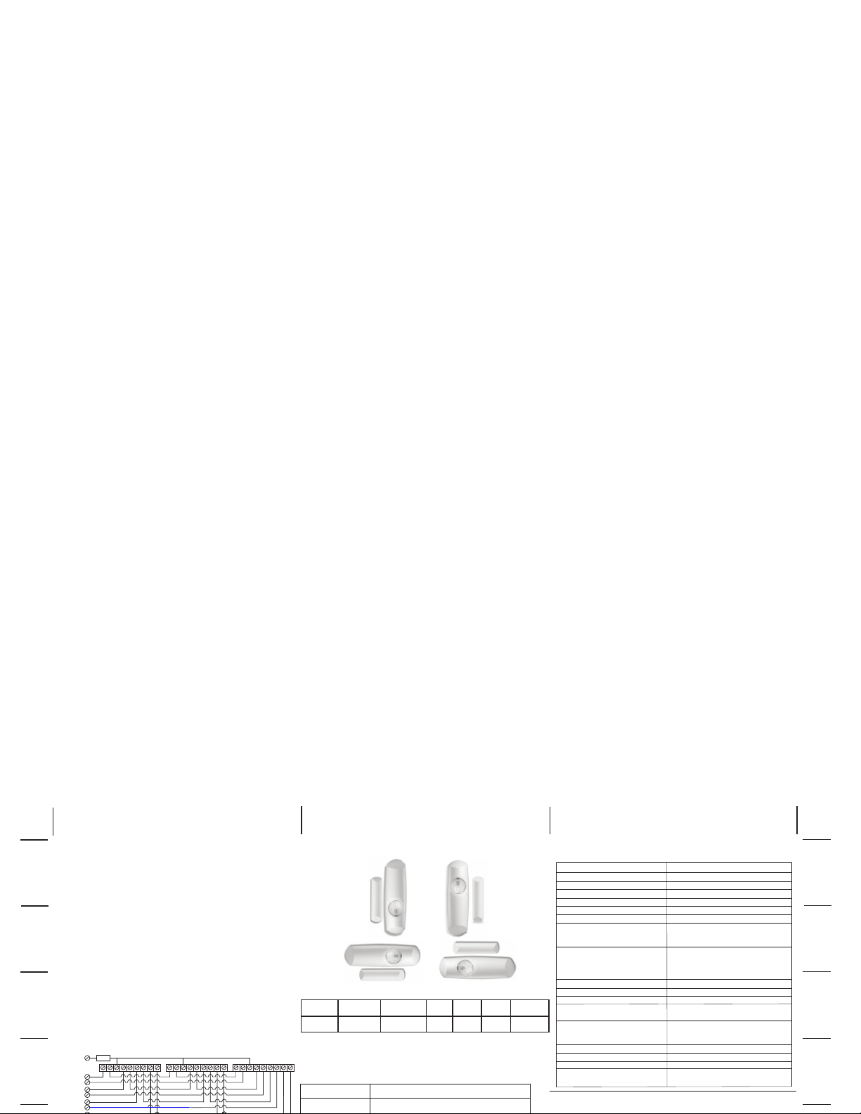
2 Install the magnet on the left side of the ShockTec Plus G3 as
indicated in Figure 3, with the following considerations:
i Mount the magnet opposite the middle of the ShockTec
Plus G3.
ii Maximum distance of the magnet from the Shocktec Plus
G3 is 20mm.
iii Position the magnet as close as possible to the same
plane level as the back surface of ShockTec Plus G3.
NOTE: Placing the magnet on the wrong side of the ShockTec Plus
G3 will cause a tamper alarm signal.
Multiple Unit Connection Procedure
Figure 2: Multiple Unit Connection Procedure
Figure 3: Magnet Mounting Positions
Table 1: Typical Detection Range
The above values are typical and are subject to practical testing, which
must be performed for each installation. In some environments, these
values may differ from the values listed above.
Surface Concrete Brick Wall Steel Glass Wood Plywood
Radius 1.5m 2.5m 3m 3.5m 3.5m 4m
Ordering Information
Part number Description
RK601SM0000A ShockTec Plus with Magnet Grade 3, White
ALARM
TAMPER
12V TO
LED
REED
SWITCH
47K
Cut
Fold
Fold
Fold
Fold
Cut
Fold
Fold
Fold
Fold
Cut
Fold
Fold
Cut
RISCO Group Limited Warranty
RISCO Group and its subsidiaries and affiliates ("Seller") warrants its products to be free from defects in materials and
workmanship under normal use for 24 months from the date of production. Because Seller does not install or connect the
Technical Data
Supply voltage 9V –16V DC
Current drain 7.5 mA Typical (14 mA Max)
Operational temperature -20°C to +55°C (-4°F to 131°F)
Storage temperature -20°C to +60°C (-4°F to 140°F)
ShockTec Plus with Magnet Grade 3
 Loading...