

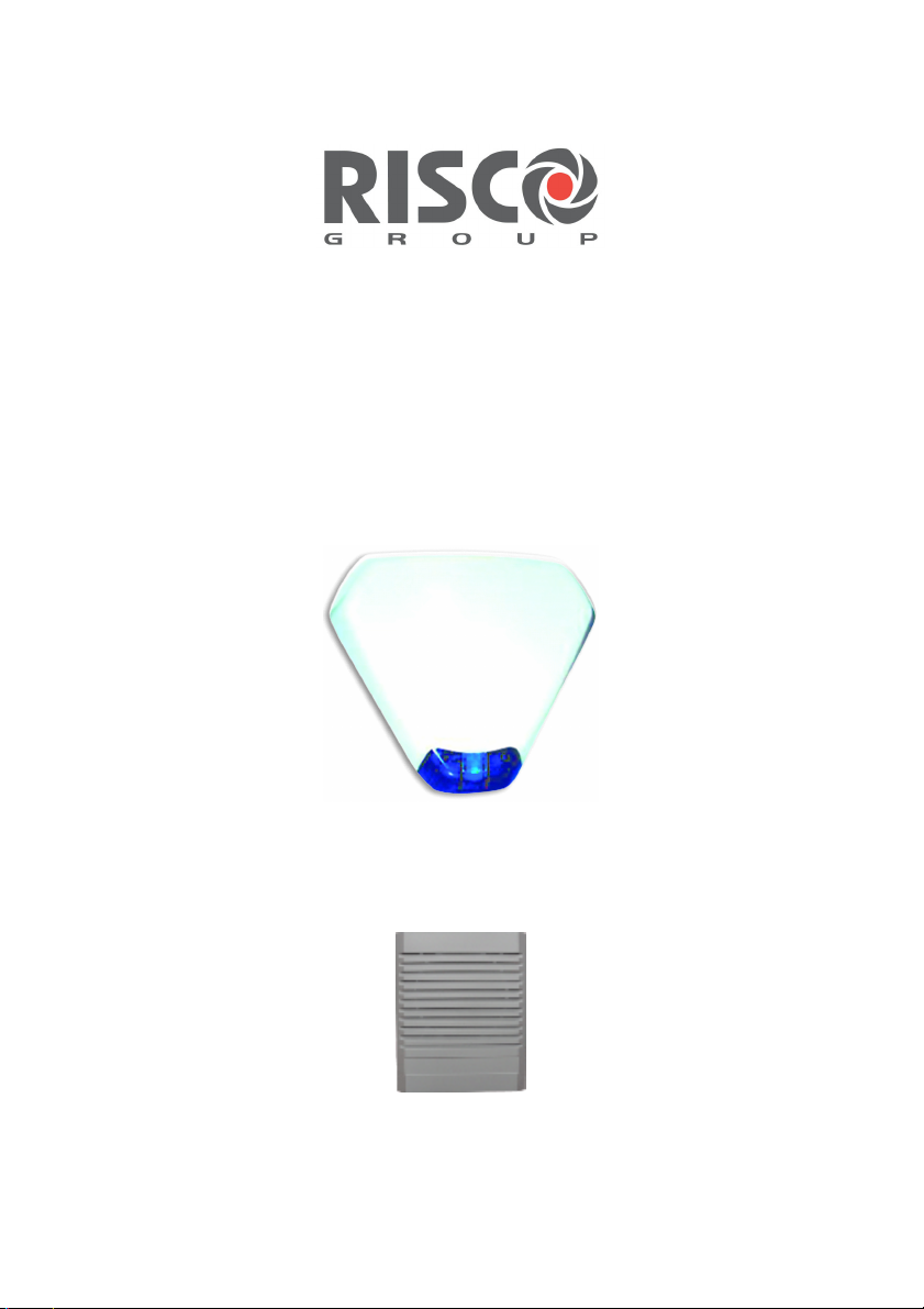
Wireless Sounder
Wireless External
Sounder
Wireless Internal
Sounder
Installation and Programming Instructions

Table Of Contents
Introduction........................................................................................................... 3
Operational Functions.......................................................................................... 3
Alarm / Tamper Indication ...................................................................................3
Low Battery Indication.........................................................................................3
Supervision .........................................................................................................3
Pre Alarm Indication............................................................................................3
Self Testing .........................................................................................................3
Installation LED Indication...................................................................................3
Installation............................................................................................................. 4
Mounting the External Sounder...........................................................................4
Mounting the Internal Sounder............................................................................6
Programming Instructions ................................................................................... 7
Engineer Programming Menu .............................................................................7
[9][2][1] Siren: Allocation ............................................................................... 7
[9][2][2] Siren: Parameters ............................................................................ 8
[9][2][3] Siren: Communication Test .............................................................. 9
[9][2][4] Siren Receiver Calibration.............................................................. 10
[9][2][5] Siren: Tamper Mute........................................................................ 10
[1][1][9] Siren Supervision Time .................................................................. 10
[1][2][35] Siren Pre Alarm Feature............................................................... 11
[6][2][6][4] Siren Report Codes.................................................................... 11
Event Log Messages................................................................................... 12
User Programming Menu ..................................................................................13
Diagnostics.................................................................................................. 13
Siren Version............................................................................................... 13
Replacing Batteries ............................................................................................ 14
Technical Information......................................................................................... 14
Electrical ...........................................................................................................14
Radio.................................................................................................................14
Environmental ...................................................................................................14
2 Wireless Sounder Instructions
Introduction
RISCO Group's two-way wireless sounders are designed to extend the signaling
capabilities of the Risco Group wireless systems within the protected area. The
wireless sounders offer an easy and flexible solution for quick installations. The
sounders are powered by their own batteries and communicate wirelessly with the
security panel using 868MHz or 433MHz frequency band. Up to 3 wireless sounders
(external or internal) can be assigned to a system.
* Sounder and siren are used interchangeably in this document.
Operational Functions
Alarm / Tamper Indication
Upon an alarm condition, the sounder sound will be activated for a period of time
defined by the system (the Bell Time Out parameter).
The maximum time that the sound will be activated is 5 minutes.
Low Battery Indication
Upon a low battery condition a trouble indication is sent to the panel.
There are 2 types of low battery indications:
Radio low battery
Speaker low battery
Supervision
Each sounder can be defined to be supervised by the panel. The system generates
a local trouble signal identifying the sounder which its signal is not received during
a predefined time, followed by a report to the Central Station (if defined).
Pre Alarm Indication
When an entry time starts, the system transmits a pre-alarm signal to the sounder.
If the system is disarmed before the entry delay time expires a cancellation signal is
sent to the sounder.
If the sounder does not receive a canceling signal within the entry delay time, the
sounder will be activated.
NOTE
:
This feature is programmable. For more information please refer to page 11.
Self Testing
Upon pressing on the reset switch located on the PCB, the sounder performs a
functional self test. The strobe flashes and a squawk will sound.
Remote testing can be performed from the system keypad or using the
Upload/Download software.
Installation LED Indication
The sounder incorporate two LEDs located on the PCB. These LEDs are enabled
when the tamper is open and 10 minutes after the tamper is closed.
Red Only: Indicates transmission time
Yellow Only: Indicates low battery
Red + Yellow (3 seconds): Confirmation of successful learning mode.
Wireless Sounder Instructions 3
Installation
Use the following instructions to mount the external and internal wireless sounders.
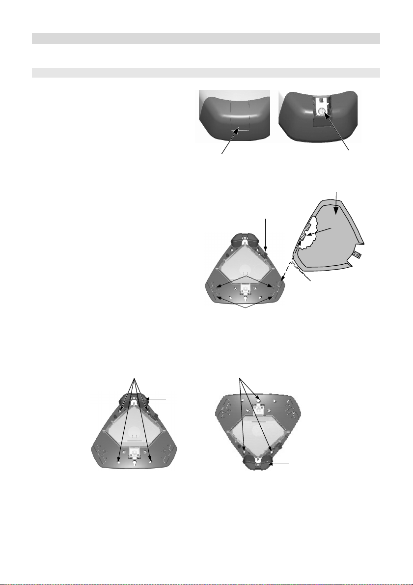
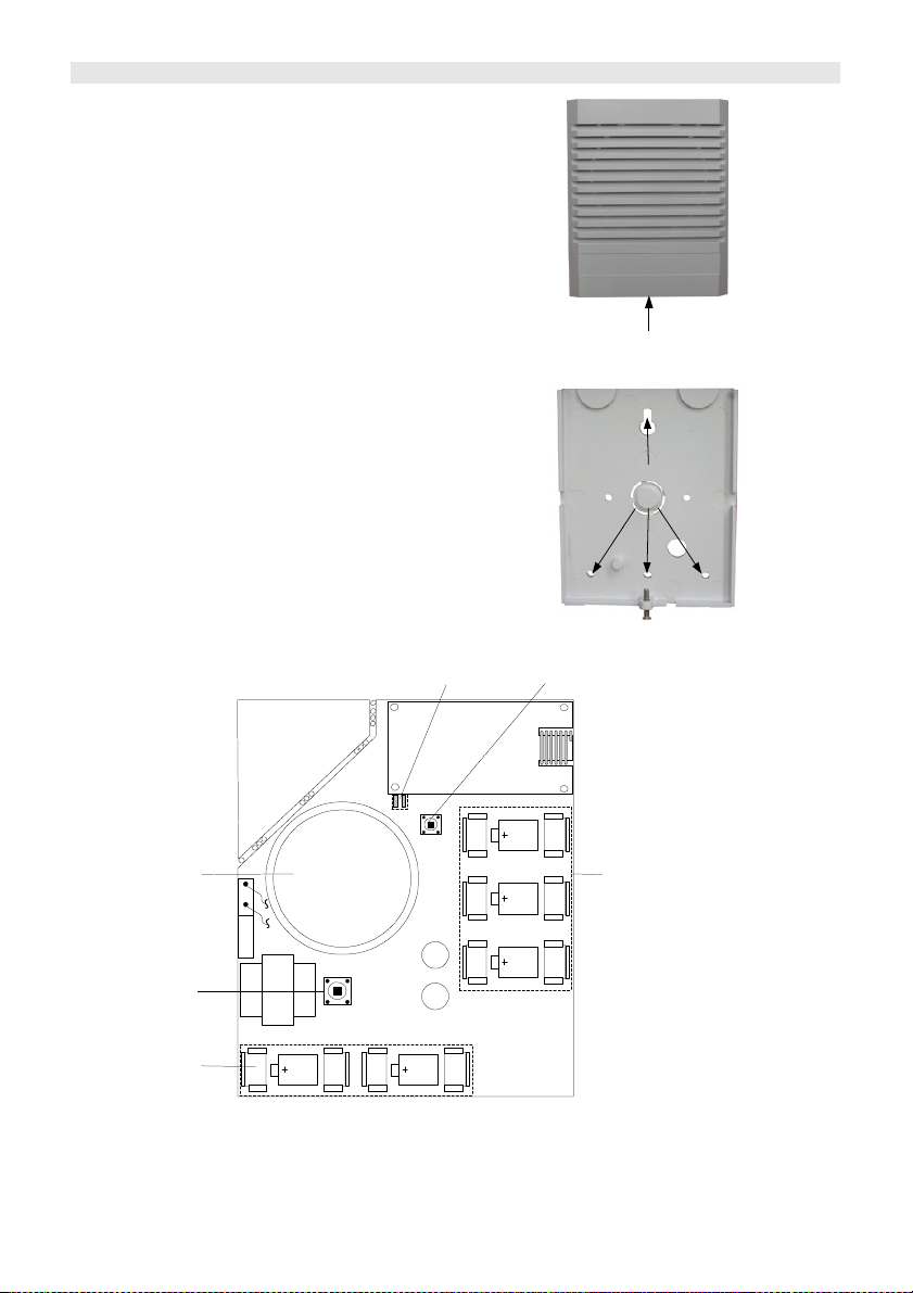
Mounting the External Sounder
1) Open the screw cover by
applying thumb pressure on the
screw cover lower part. When
raised, push outwards. Once
you have gained access to the
cover screw, open screw and lift
the cover away until cleared from
the back plate.
Screw cover -
Lower section
2) Once the cover has been removed it
may be slid into one of the Cover
Retaining Clip -
Inner Cover
Holder Clips. This is done by placing
the cover next to the cover holding
clips and then sliding it into place. To
release cover, press the release tab
and slide cover out.
Release Tabs
3) To reach the PCB release the inner
cover and lift the cover until it locks in
the raised position.
Cover Holder
Clips
into the Cover holder clips
4) Position the sounder base plate against the wall and mark the securing holes
according to the strobe required position. The unit should be mounted to the wall using
at least three 2" No 10 screws and suitable wall anchors.
Fixing points with
strobe at the top
Fixing points with
strobe at the bottom
Siren cover
screw
Cover - Exploded View
Tab
Sliding pattern of Tab
Strobe
Strobe
4 Wireless Sounder Instructions
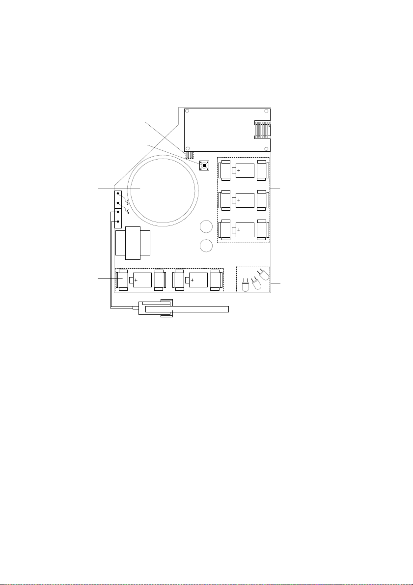
5) Insert the supplied batteries in the metal clips according to the polarity.
6) The sounder is ready for communication set up with the system.
7) Once the communication set up is completed, close the inner cover and reattach the
outer cover.
Two Indication
LEDs
Reset Switch
Speaker
Speaker & Strobe
Batteries
(6V, Serial
Connection)
R
E
K
A
E
P
S
R
E
P
M
A
T
External Sounder - PCB Diagram
Radio Batteries
(3V, Parallel
Connection)
Strobe
LEDS
Wireless Sounder Instructions 5
Mounting the Internal Sounder
the front cover by removing the cover
1. Open
locking screw located at the bottom of the
unit.
2. Hold the back plate against the wall and
mark the locations of the mounting holes.
Drill the desired mounting holes and insert
screw anchors.
3. Mount the back unit to the wall using the
supplied screws.
4. Insert the supplied batteries paying
attention to the polarity
5. Perform communication set up with the
control panel
6. Once communication setup is completed,
close the cover and locking screw.
Two Indication
LEDs
Remove cover
locking screw
Fixing Points to
Wall
Reset
Switch
Speaker
R
E
K
A
E
P
S
R
E
P
M
A
T
Tamper
Speaker Batteries
(6V, Serial
Connection)
Internal Sounder - PCB Diagram
6 Wireless Sounder Instructions
Radio Batteries
(3V, Parallel
Connection)

Programming Instructions
The following section describes programming options added relating to the
programming of the wireless sounder. Up to 3 wireless sounders (external or internal)
can be assigned to the system.
We recommend reading and fully understanding the system Installation and User
manuals, before programming the sounder.
Engineer Programming Menu
To access the sounder menu
1. From the main engineer menu press [9] to access the More "Devices menu".
2. Press [2] for Siren.
3. You are now in the sounder submenus as described below.
[9][2][1] Siren: Allocation
The sounder must identify itself to the system's receiver by writing its ID into the
System.
Step 1: Introducing the Sounder to the System
1. After accessing the siren menu, press [1] for the Allocation menu
2. Select the sounder ID you want to assign.
3. Place the cursor over the Type filed. Use the key to choose one of the
following options and then press [#] :
NONE
ODWS1: Outdoor wireless sounder
INWS1: Indoor wireless sounder
NOTE:
After selecting the NONE option the system will ask you whether to erase the sounder or not.
4. Use the key to choose if the sounder will be audible [Y] or silent [N] and
press [#].
5. Use the key to choose if the squawk sound will be audible [Y] or silent [N]
and press [#].
6. Use the key to choose if the squawk strobe is enabled [Y] or disabled [N]
and press [#].
NOTE:
The definition of the squawk strobe is applicable only for the outdoor (ODWS1) sounder.
Wireless Sounder Instructions 7

Step 2: Setting communication with the system
1. After adding the sounder to the panel, the sounder must identify itself to the
system's receiver by writing its ID into the system's receiver. Select the
appropriate option as follows:
Press [1] to Skip to the next sounder assignment
Press [2] to allocate the sounder into the system. Send a write
signal (within 255 seconds) from the sounder as follows:
a. Press the reset switch on the sounder.
b. After a squawk is sounded and the sounder's
strobe flashes (only in outdoor sounder) you
have 10 seconds to press on the tamper switch
for at least 3 seconds.
If the sounder is successfully recognized, the
system will sound a confirmation beep, the
sounder will initiate a squawk sound and the 2
LEDs on the sounder will flash for 3 seconds.
Press [3] to erase the sounder from the system memory.
Press [4] to select whether the sounder will be supervised or not.
2. Repeat the process for other sounders in the system (up to 3).
[9][2][2] Siren: Parameters
Using this menu you can define parameters that reflect the operation of the sounder.
To set the sounder parameters
1. From the engineer menu, access the siren parameters submenu, Quick Key
[9][2][2].
2. Enter the number of the sounder that you want to program and then press [#].
You can now program the sounder parameters.
NOTE:
For internal sounder (INWS1) only the Volume parameter is available.
Siren: Parameters
Quick Keys Parameter
[9][2][2][1]
Strobe Control
Defines the Strobe operation mode.
[9][2][2][1]
[1]
Always Off
The strobe is deactivated
[9][2][2][1]
[2]
Follow Bell (Default)
The strobe is activated when the sounder bell is triggered.
[9][2][2][1]
[3]
Follow Alarm
The strobe is activated when an alarm event occurs in the system.
8 Wireless Sounder Instructions

[9][2][2][2]
If the sounder’s squawk strobe is defined as NO (Refer to Allocation section) this
[9][2][2][2]
[1]..[5]
[9][2][2][3]
[9][2][2][4]
[9][2][2][4]
[1]
[9][2][2][4]
[2]
[9][2][2][4]
[3]
Strobe Blink
Defines the number of times that the strobe will flash per minute.
Strobe Blink options
[1] 20 times per minute
[2] 30 times per minute
[3] 40 times per minute (Default)
Strobe Arm Squawk
[4] 50 times per minute
[5] 60 times per minute
Default: 05 Range: 01-20
(seconds)
The time that strobe blinking will continue when arm is performed.
NOTE:
parameter will be ignored.
Volume
Defines the sounder sound volume for the following system modes.
The sound volume range is between 0 (silent) to 5 (maximum
volume).
Exit / Entry
The sound produced during exit/entry time
Default: 0
Alarm
The sound produced during alarm. (Default: 9)
Squawk
The sound produced during squawk sounds (Default: 9)
[9][2][3] Siren: Communication Test
The sounder communication test performs a communication test between the sounder
receiver and the system. The value displayed indicates the receiving level of the signal
sent from the system to the sounder's receiver.
To perform communication test
1. From the engineer menu access the siren communication test submenu, Quick
Key [9][2][3].
2. The system sends a test signal to the sounders. A number between 00-99
indicates the strength of the communication signal between the system and the
sounder.
NOTE:
For successful communication, the strength of the signal should be higher that the sounder receiver
noise threshold level (see quick key [9][2][4]) .
Wireless Sounder Instructions 9

[9][2][4] Siren Receiver Calibration
ion time of the system receiver (Quick key [1][3][3]) should be higher than the
This feature establishes the threshold noise level of the wireless sounder receiver for
successful communication with the system.
To calibrate the sounder receiver
1. From the engineer menu access the siren receiver calibration submenu, Quick
Key [9][2][4].
2. Select the sounder for which you want to calibrate its receiver.
3. To perform a new automatic calibration, use the key to select [Y].
After the calibration process is accomplished, the new noise threshold level is
displayed.
4. To confirm the new threshold level, press [#] or change the threshold level
manually and then press [#].
[9][2][5] Siren: Tamper Mute
Selecting this option will disable the tamper sound during the current installation
programming period.
NOTE:
An ongoing tamper alarm will not be disabled.
[1][1][9] Siren Supervision Time
System: Timers
Quick Keys Parameter Default Range
[1][1][9]
Accessory Supervision Time
60 minutes 00-255 minutes
Specifies the siren supervision time parameter, i.e. if set to 60
minutes the siren will send a supervision signal every 60 minutes.
If any of the sounders does not transmit to the panel at least once,
during the supervision time of the system receiver (Quick Key
[1][3][3] ) the system will regard the sounder as Lost.
IMPORTANT:
The supervis
accessory supervision time ([1][1][9]) in order to eliminate false lost event.
10 Wireless Sounder Instructions

[1][2][35] Siren Pre Alarm Feature
This wireless sounder incorporates a pre alarm feature that enhances the security of
the system, by producing a local alarm in case of the sabotage.
NOTE:
In the UK version of the system the quick key of this parameter is [1][2][44].
System: Control
Quick Keys Parameter Default
[1][2][35]
Siren Pre Alarm
No
Specifies if the system will send a Pre Alarm message to the sounder
while an entry delay starts.
Yes: The system sends a pre alarm signal to the sounder at the
beginning of the entry delay. If the sounder does not receive a
cancellation signal from the system at the end of the entry time, the
sounder goes into alarm.
No: Pre Alarm disabled
[6][2][6][4] Siren Report Codes
The following are the new report codes related to the wireless sounders.
Report codes Manual Wireless Siren
Quick Keys Parameter
[6][2][6][4]
[1]
Tamper
Tamper alarm from sounder X
[6][2][6][4]
[2]
Tamper Restore
Tamper alarm restore from sounder X
[6][2][6][4]
[3]
Battery Trouble
Report code for a low battery condition in a wireless sounder
[6][2][6][4]
[4]
Battery Trouble Restore
Report code for the correction of a low battery condition
[6][2][6][4]
[5]
Lost Trouble
A report code that indicates the following condition: If any of the
sounders does not respond to any request from the system, during
the supervision time of the system receiver
(Quick Key [1][3][3] ), the
system will regard the sounder as Lost.
[6][2][6][4]
[6]
Lost Trouble Restore
Restore is established when the system receives any signal from the
sounder.
Wireless Sounder Instructions 11

Event Log Messages
The following list details the wireless sounder dedicated event messages, as displayed
on the system LCD display:
LCD Text Event Description
Tamper Siren=X Tamper alarm from wireless sounder X
Tmp rstr Siren=X Tamper alarm restore from wireless sounder X
Spkr low bat S=X Speaker low battery trouble
Spkr l.bat rsS=X Speaker low battery restore from sounder X
Radio l.bat S=X Radio low battery trouble
Radio l.bat rs=X Radio (Transceiver) low battery restore from sounder X
Siren=X Lost Sounder X is regarded as lost following supervision test.
Siren=X Lost Rst The System received a signal from sounder X after it has
been regarded as lost
12 Wireless Sounder Instructions

User Programming Menu
Diagnostics
The diagnostics menu enables to test parameters that reflect the operation of the
sounder.
To perform diagnostics:
1. From the user menu press [] [4] to access the Maintenance menu.
2. Enter the Engineer code (or sub-engineer) and press [#].
3. Press [7][1] to access the Siren diagnostic menu.
4. Enter the digit representing the sounder you want to test and then press [#].
The system will perform the diagnostics test and a list of test parameters
will appear, as indicated in the table below.
5. Use the arrow keys to view the diagnostics test results.
NOTE:
The diagnostic features can be also performed from Upload/Download software, locally or remotely.
Maintenance: Siren Diagnostics
Quick Keys Parameter
[4][7][1]
Siren Diagnostics
Speaker batteries voltage: Tests the selected sounder’s speaker
batteries voltage.
Radio (Transceiver) batteries voltage: Tests the selected sounder’s
radio's batteries voltage.
Siren Version
This menu displays information regarding the sounder's version. Repeat steps 1 to 4 in
the Siren diagnostic section with the exception of pressing [7][2] in step 3 for the Siren
version option.
Maintenance: Siren Version
[4][7][2]
Siren Version
Sounder part number:
F=Frequency (868MHz / 433MHz) V=Siren type (Internal/External),
C= lens Color
Sounder software version
Sounder software date
Sounder software checksum
Wireless Sounder Instructions 13

Replacing Batteries
1. To silence the tamper alarm enter the engineer programming mode, quick key
[9][2][5] and activate the Tamper Mute option.
2. Remove the sounder cover as described in the installation section.
NOTE:
If required you can silence a tamper alarm by pressing the RESET Switch.
3. Remove the old batteries from the metal clips and replace with new ones. Pay
attention to the polarity.
4. Press the RESET switch.
5. Close the cover and fasten the cover locking screw.
NOTE:
Dispose of batteries according to your local regulations
Technical Information
Electrical
Power Supply 5 X CR123, 3V Lithium Battery (3 batteries for
the Radio Transceiver, 2 batteries for the
Speaker/Strobe, see External and Internal
Sounder - PCB Diagrams on pages 5 and 6)
Battery life 3 years (typical)
Speaker sound level 105 dB @ 1 meters (adjustable)
Strobe lens (External sounder) Polycarbonate, available in amber, red, blue or
transparent
Strobe flash rate (External
sounder)
Size: External sounder (HxWxD) 300x 325x70 mm (11.8 x12.8x2.8 inch)
Size: Internal sounder (HxWxD) 145 x 120 x 50 mm (5.7x4.7x2 inch)
External sounder Weight
(batteries included)
Internal sounder Weight
(batteries included)
Radio
Radio type Two Way Narrow band
Frequency 868 MHz or 433MHz
Range up to: 150m (492’) Line of sight
Supervision Yes
Modulation Type ASK
Environmental
Temperature -25°C to 60°C (-4°F to 140°F)
IP Rating IP 44
Environmental Class Class IV
14 Wireless Sounder Instructions
60 times per minute (maximum)
1 Kg (35.2 oz)
0.44Kg (15.52 oz)

FCC & IC notes
This equipment has been tested and found to comply with the limits for a Class B digital
device, pursuant to part 15 of the FCC Rules.
These limits are designed to provide reasonable protection against harmful interference
in a residential installation. This equipment generates uses and can radiate radio
frequency energy and, if not installed and used in accordance with the instructions, may
cause harmful interference to radio communications.
However, there is no guarantee that interference will not occur in a
particular installation. If this equipment does cause harmful interference to radio or
television reception, which can be determined by turning the equipment on and off, the
user is encouraged to try to correct the interference by one or more of the following
measures:
• Reorient or relocate the receiving antenna.
• Increase the separation between the equipment and the receiver.
• Connect the equipment into an outlet on to a different circuit from that to which
the receiver is connected.
• Consult the dealer or an experienced radio/TV technician for help.
Changes or modifications to this equipment which are not expressly approved by the
party responsible for compliance (RISCO Ltd) could void the user's authority to operate
the equipment.
FCC ID: JE4RWRT433
IC: 6564-RWRT433
RTTE Compliance Statement
Hereby, RISCO Group Ltd, declares that these products (Wireless external siren
and wireless internal siren) are in compliance with the essential requirements and
other relevant provisions of Directive 1999/5/EC.
Wireless Sounder Instructions 15

RISCO
RISCO Group Ltd. and its subsidiaries and affiliates ("Seller") warrants its products to be free from
defects in materials and workmanship under normal use for 12 months from the date of production.
Because Seller does not install or connect the product and because the product may be used in
conjunction with products not manufactured by the Seller, Seller cannot guarantee the performance
of the security system which uses this product. Seller's obligation and liability under this warranty is
expressly limited to repairing and replacing, at Seller's option, within a reasonable time after the
date of delivery, any product not meeting the specifications. Seller makes no other warranty,
expressed or implied, and makes no warranty of merchantability or of fitness for any particular
purpose.
In no case shall seller be liable for any consequential or incidental damages for breach of this or
any other warranty, expressed or implied, or upon any other basis of liability whatsoever.
Seller's obligation under this warranty shall not include any transportation charges or costs of
installation or any liability for direct, indirect, or consequential damages or delay.
Seller does not represent that its product may not be compromised or circumvented; that the
product will prevent any persona; injury or property loss by burglary, robbery, fire or otherwise; or
that the product will in all cases provide adequate warning or protection. Buyer understands that a
properly installed and maintained alarm may only reduce the risk of burglary, robbery or fire without
warning, but is not insurance or a guaranty that such will not occur or that there will be no personal
injury or property loss as a result.
Consequently seller shall have no liability for any personal injury, property damage or loss based
on a claim that the product fails to give warning. However, if seller is held liable, whether directly or
indirectly, for any loss or damage arising from under this limited warranty or otherwise, regardless
of cause or origin, sellers maximum liability shall not exceed the purchase price of the product,
which shall be complete and exclusive remedy against seller.
No employee or representative of Seller is authorized to change this warranty in any way or grant
any other warranty.
WARNING: This product should be tested at least once a week.
Group Limited Warranty
16 Wireless Sounder Instructions

Contacting RISCO Group
RISCO Group Ltd. is committed to customer service and product support. You can
contact us through our website (www.riscogroup.com) or at the following addresses:
UNITED KINGDOM - RISCO Group U.K. Ltd.
National Sales number: 0870 60 510000
Tel: +44-161-655-5500
Fax: +44-161-655-5501
E-mail: info@riscogroup.co.uk
Tech: 00 44 161 655 5600
Fax: 00 44 161 655 5610
E-Mail: technical@riscogroup.co.uk
U.S.A - Rokonet Industries U.S.A Inc.
Toll Free:1-800-344-2025
Tel: (305) 592-3820
Fax: (305) 592-3825
Email: sales@rokonetusa.com
ITALY - RISCO Group S.R.L
Tel: +39 (02) 392-5354
Fax: +39 (02) 392-5131
Email: info@riscogroup.it
SPAIN - Rokonet Iberia S.L
Tel: + 34 (91) 490-2133
Fax: +34 (91) 490-2134
Email: sales@rokonet.es
BRAZIL - Rokonet Electronics Ltda.
Tel: +55 (11) 3661-8767
Fax: +55 (11) 3661-7783
Email: rokonet@rokonet.com.br
ISRAEL - RISCO Group Ltd.
Tel: +972 (3) 9637777
Fax: +972 (3) 9616584
Email: info@riscogroup.com
All rights reserved.
No part of this document may be reproduced in any form without prior written
permission from the publisher.
© RISCO Group 07/06 5INRWS50 C
 Loading...