

Risco RW132KPP1356 User Manual

EN
Agility 2
Agility 2----Way
Agility 2Agility 2
2W WL LCD Keypad, 915
Model: RW132KPPW3
Way
Way Way
Table of Contents
Table of Contents
Table of ContentsTable of Contents
INTRODUCTION .................. ........... ........... .......... ........... ........... .......... ........... ........... ... 4
MAIN FEATURES ............ ........... ........... .......... ..........
COMMUNICATION SETUP ..... ........... ........... .......... ........... ........... .......... ........... ........ 4
MOUNTING THE KEYPAD ..... ........... .......... ........... ........... .......... ........... ........... ......... 5
MAIN USER OPERATIONS .......... ........... .......... ........... ........... .......... ........... ........... .... 6
COMMON OPERATIONS ........... ........... .......... ........... ........... .......... ........... ........... ..... 6
KEY OPERATION DURING PROGRAMMING MODE ....... .......... ........... ........... ... 6
ADVANCED OPERATIONS ................... ........... .......
LEDS INDICATION ....... ........... ........... .......... ........... ........... .......... ........... ........... .......... 7
SLEEP MODE........ ........... .......... ........... ........... .......... ........... ........... .......... ........... ........... 7
REPLACING BATTERIES .......... .......... ........... .......... ........... ........... .......... ........... ......... 7
CHANGING KEYPAD PARAMETERS ......... ........... ........... .......... ........... ........... ........ 7
TECHNICAL SPECIFICATION ........ ........... ........... .......... ........... ........... .......... ........... . 8
3
INTRODUCTION
INTRODUCTION
INTRODUCTIONINTRODUCTION
The 2-Way keypad is used to remotely program and operate the Agility security
system. Being bi-directional the 2-Way keypad receives a reply status indication from
the panel for each command that it has sent to the panel. To use functions of the
keypad you can use a code or a proximity tag.
COMMUNICATION SETUP
COMMUNICATION SETUP
COMMUNICATION SETUPCOMMUNICATION SETUP
The Keypad is automatically programmed to your control panel during the on-line
installation wizard setup. If you later purchase an extra keypad you can enroll it as
follows:
To quickly allocate a keypad at the control panel:
If the control panel is not already in Learn mode, press the button on the control
panel for 5 seconds; the unit beeps once as it enters Learn mode (all the LEDs also light
up, one after the other).
Make sure batteries are installed in each keypad before allocating them.
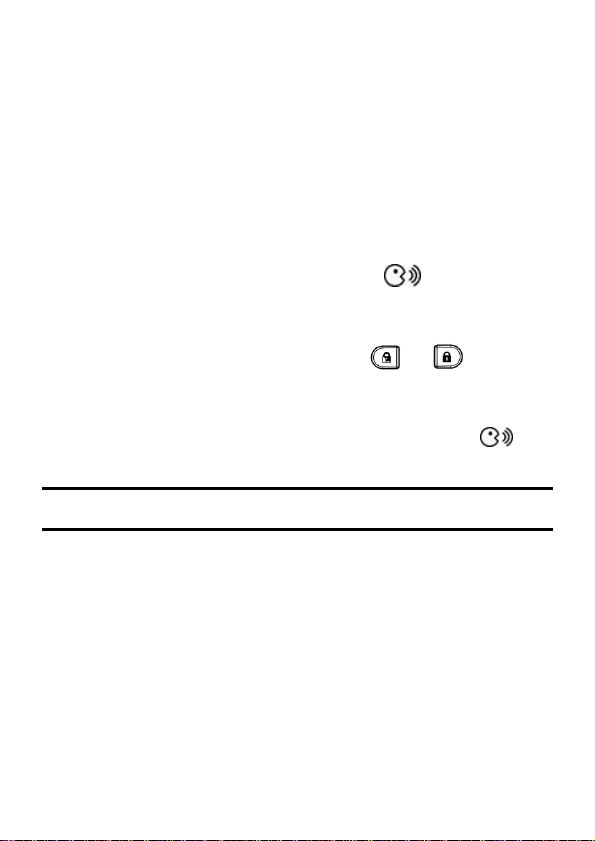
Send a signal transmission from the keypad by pressing and
simultaneously for at least 2 seconds; the control panel beeps once to accept or beeps
three times to reject. Once accepted, the system announces the device type and its zone
(for example, “Keypad, zone 1”).
When the keypads have been enrolled, short-press the control panel button to
exit Learn mode; the unit beeps once and the LEDs stop flashing.
Note:.
Note: For future use, it is recommended to write down the keypad description, zone number, and
installation location of each allocated keypad.
4
MOUNTING THE KEYPAD
MOUNTING THE KEYPAD
MOUNTING THE KEYPADMOUNTING THE KEYPAD
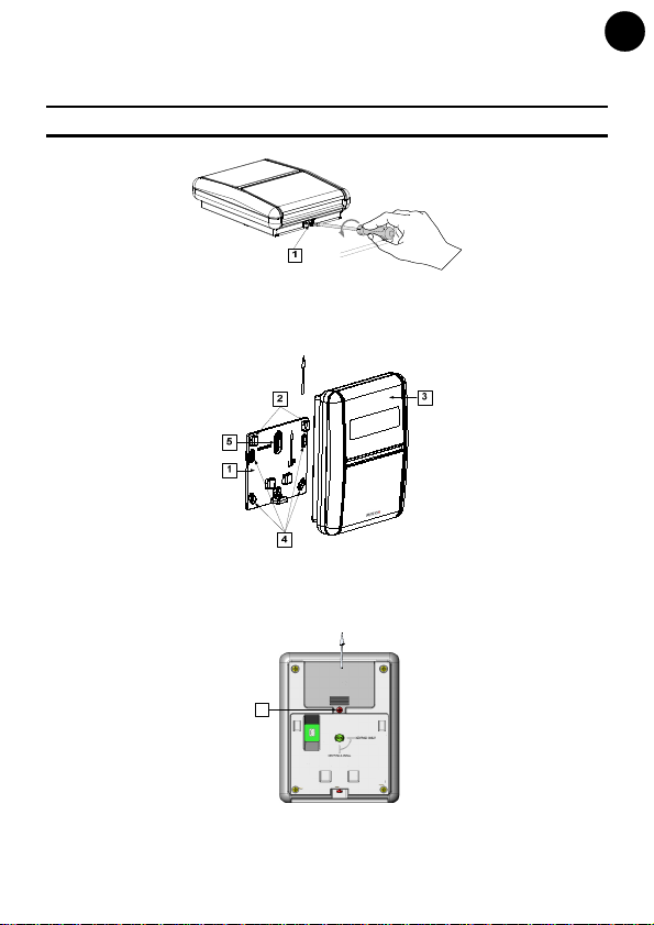
Mount the keypad on the wall using the supplied mounting bracket.
Note: Before mounting the keypad test the keypad communication with the system.
1. Release the Mounting bracket captive screw (1).
EN
Figure 1
2. Slide up the Main Unit (3) to release it from the two mounting bracket's locking tabs
(2).
3. Mount the bracket.
Figure 2
4. Release the battery cover screw (1) and place the supplied 3 batteries.
5. Close the battery compartment and mount the keypad to the mounting bracket in a
reverse sequence to the removal.
1
Tamper
Figure 3
5
 Loading...