

Risco RW132KL1, RW132KL1P Instruction Manual
Agility 2-Way Wireless
Slim Keypad
Model
ModelModel
Modelssss: RW132KL1
: RW132KL1: RW132KL1
: RW132KL1,
, ,
, RW132KL1P
RW132KL1PRW132KL1P
RW132KL1P
Instruction Manual
Instruction ManualInstruction Manual
Instruction Manual

Agility 2
Agility 2Agility 2
Agility 2----Way Wireless Slim
Way Wireless SlimWay Wireless Slim
Way Wireless Slim
Outdoor
OutdoorOutdoor
Outdoor Keypad
Keypad Keypad
Keypad
Table of Contents
Table of ContentsTable of Contents
Table of Contents
INTRODUCTION 3
M
AIN FEATURES
3
COMMUNICATION SETUP 3
MOUNTING THE KEYPAD 4
FULL FUNCTIONAL MODE 5
U
SER OPERATIONS
5
LEDS I
NDICATION
6
BYPASS UNIT MODE 7
U
SER OPERATION
7
BUZZER INDICATION 7
REPLACING BATTERIES 7
CHANGING KEYPAD PARAMETERS 8
USING THE PROXIMITY TAG 9
TECHNICAL SPECIFICATION 9

3
INTRODUCTION
The Agility version-3-compatible 2-Way Wireless Slim Keypad comes in two models:
RW132KL1P—a black protection-insulated outdoor model empowered with a
proximity reader
RW132K1 — a white indoor model
operates in either of two modes:
• Full function Mode: Wireless LED operating keypad
• Bypass unit Mode: Used to activate an entry countdown period
Being bi-directional the 2-Way keypad receives a reply status indication from the panel
for each command that it has sent to the panel.
To use functions of the keypad you can use a proximity tag (1P only) or a code.
Main Features
Bi-directional wireless communication
Up to three wireless keypads per system
Power-save light sensor
Proximity tag operation
Wall tamper protection
Battery economy mode
Wireless doorbell function
2 operation modes
(1P) outdoor certified IPXXXX
COMMUNICATION SETUP
The 2-Way Slim Outdoor Keypad must identify itself to the system receiver. This can be
done by entering the 11-digit serial number of the keypad into the system or using RF
mode.
Setup communication:
1. Set the system to Learn Mode by RF or by Code.
2. Send an allocation message *.
♦ By RF communication: Send a Write message by pressing both keys
simultaneously for at least 2 seconds.
♦ By Code: Enter the keypad's 11 digit serial code number
3. The system automatically recognizes the device and allocates it the next available
index number. The system will announce the keypad device type and the place it
has been allocated to.
4. If required to change the keypad's default settings, configure the keypad's
parameters according to the system installation manual.
4
*
Note: Adding the keypad to the system can be done remotely using the Configuration Software.
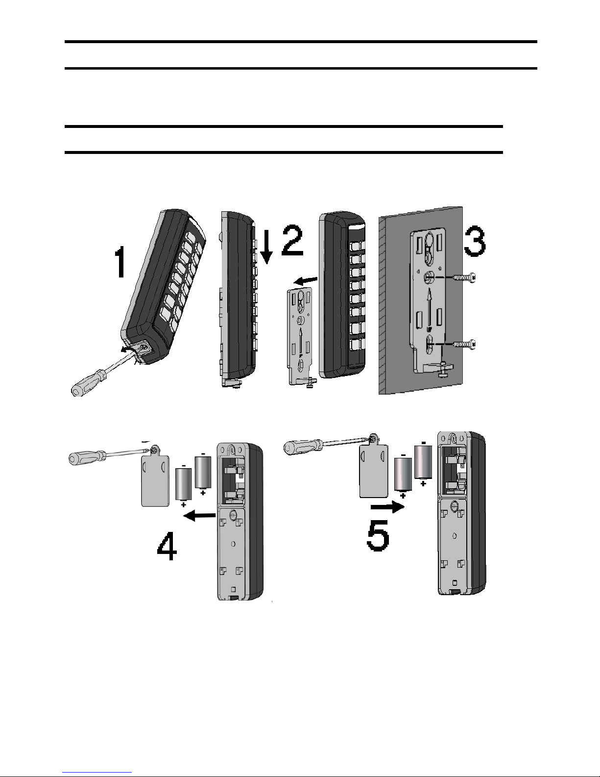
MOUNTING THE KEYPAD
Note: Before mounting the keypad, test the keypad communication with the system.
To mount the keypad on the wall using the supplied mounting bracket.
1. Remove locking pin securing the mounting bracket to the unit(1).
2. Separate the mounting plate from the keypad's main unit (2).
3. Mount the bracket to the wall using the supplied screws (3).
4. Release the battery cover screw and place the supplied two batteries. Pay attention to
polarity (4).
5. Close the battery compartment (5A). Mount the keypad to the bracket (5B).
 Loading...