

Risco RP432KP02 Installation And User Manual
LCD Panda Keypad &
LCD Panda Proximity Keypad
Installation and User Guide
Models: RP432KPP2, RP432KP02
EN
FR ES IT NL

2
Language Page
3
10
18
26
34
EN
FR
ES
IT
NL
3
Introduction
The user-friendly wired LCD & Proximity keypad enables simple operation and
programming of the LightSYS (version 5.63 and above) and ProSYS Plus (version
1.2 and above) security systems, and for the CS (Version 3.1.0.0003).
Main Features
• Optional built-in proximity tag reader
• Wall mounting by screws
• Wall tamper protection
• Modern look and feel
• Simple to install with incorporated mounting bracket
Installation
Mounting the Keypad
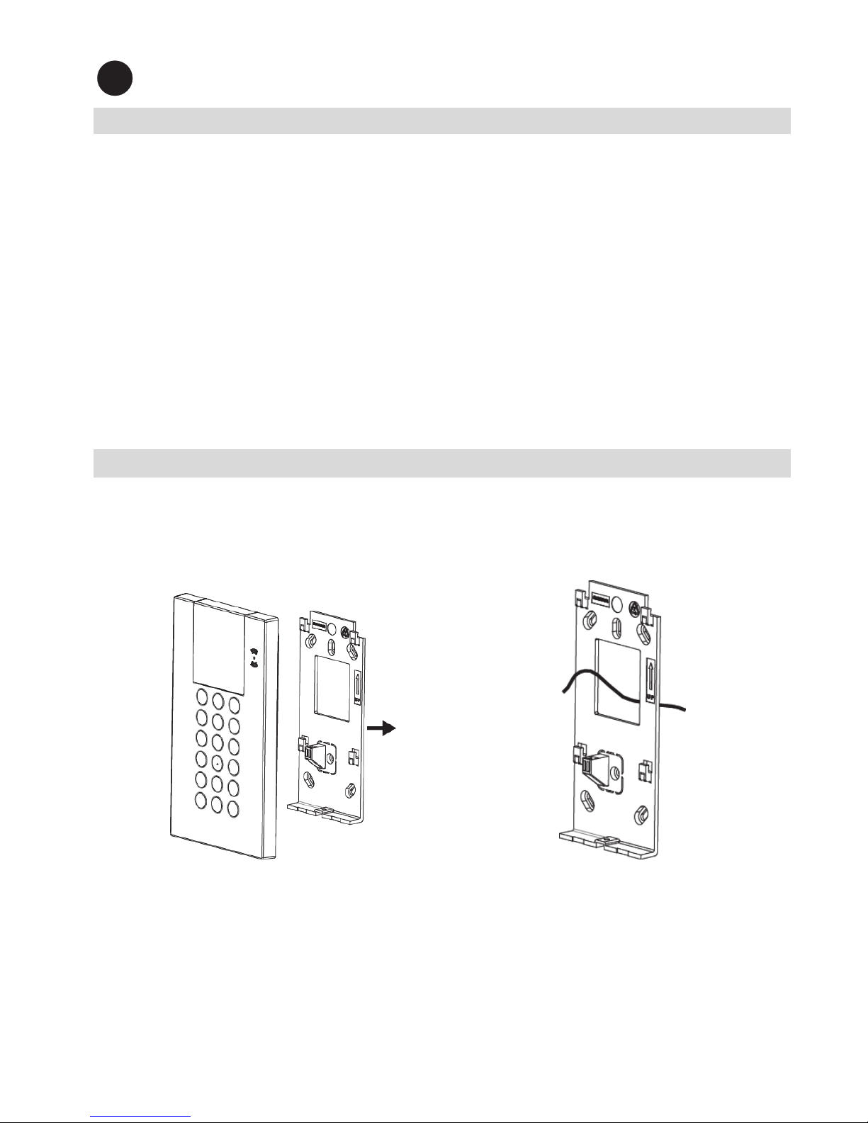
Mount the keypad on the wall using the supplied mounting bracket.
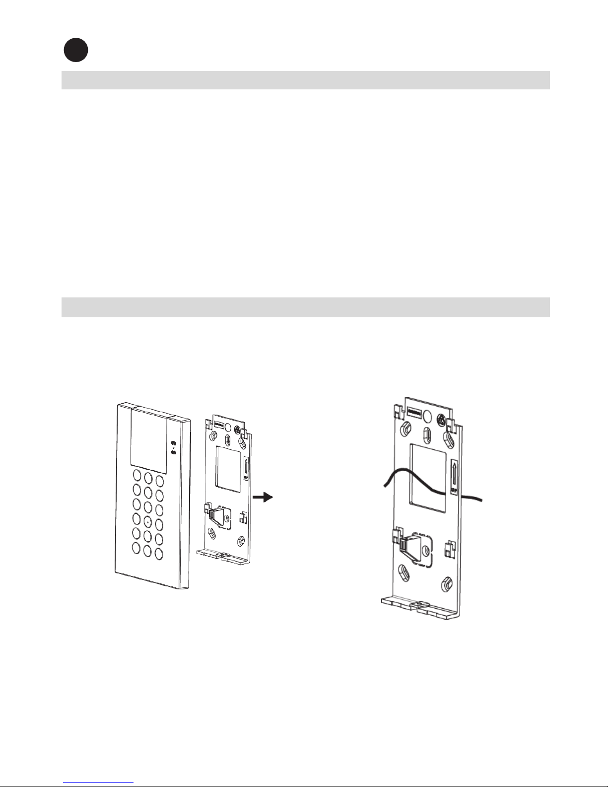
To mount the keypad:
Figure 1 Figure 2
1. Separate the mounting bracket from the keypad (see Figure 1).
2. Insert the wires through the hole in the mounting bracket (see Figure 2).
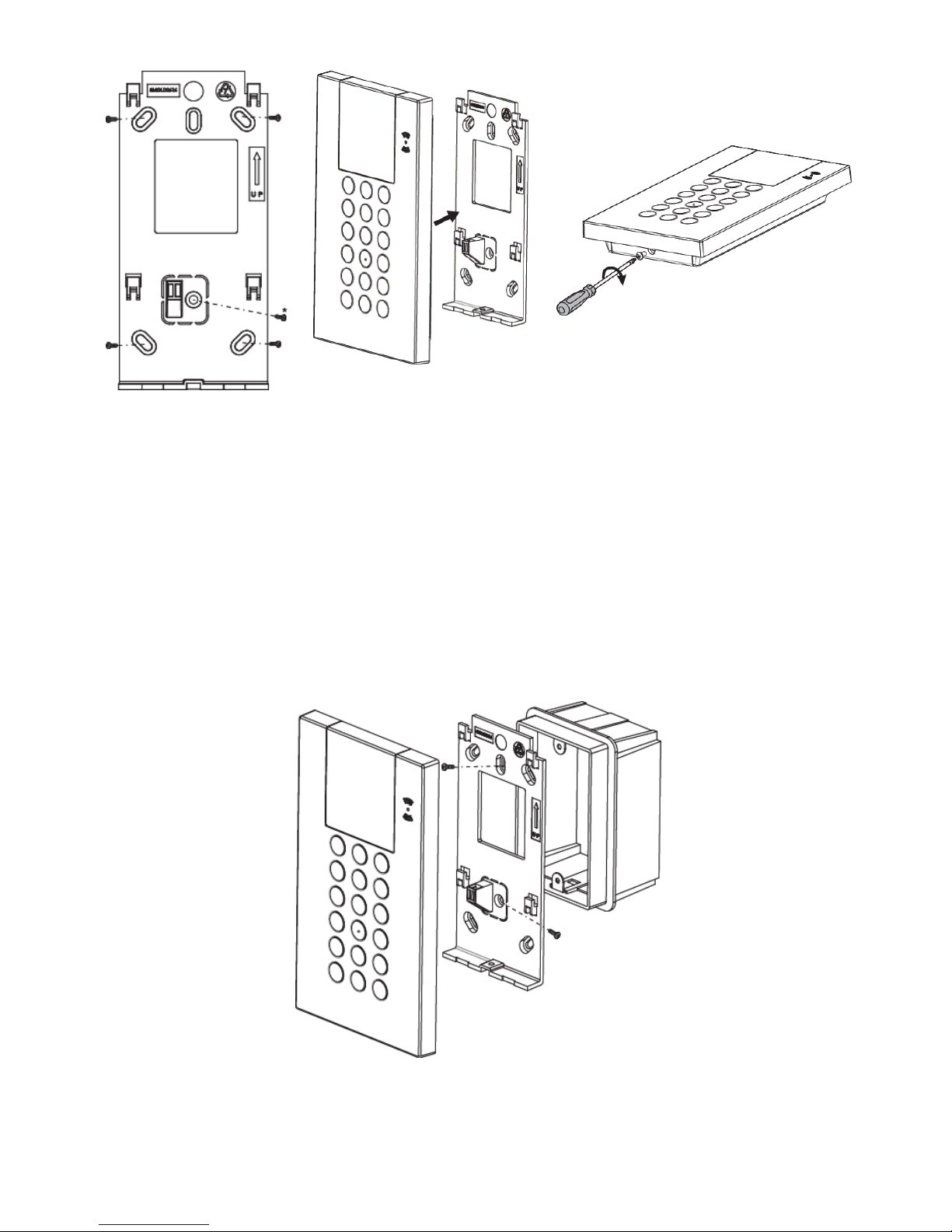
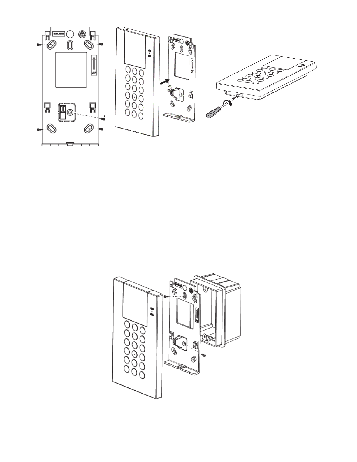
3. Use the mounting holes as a template and secure the mounting bracket to the
wall using 4 screws and 1 extra screw for the tamper (see Figure 3).
EN
4
Figure 3
* Used for tamper
Figure 4 Figure 5
4. Connect the wires to the (AUX, COM and BUS) connector shown in Figure 7.
5. Mount the keypad to the mounting bracket (see Figure 4).
6. Insert the fastening screw to lock the keypad (see Figure 5).
Mounting on Gang Box (Optional):
1. Repeat steps 1 to 2 in the previous procedure.
2. Secure the mounting bracket to the Gang Box using the two screws as
illustrated in Figure 6.
Figure 6
3. Mount the keypad to the mounting bracket and insert the fastening screw to
lock the keypad
5
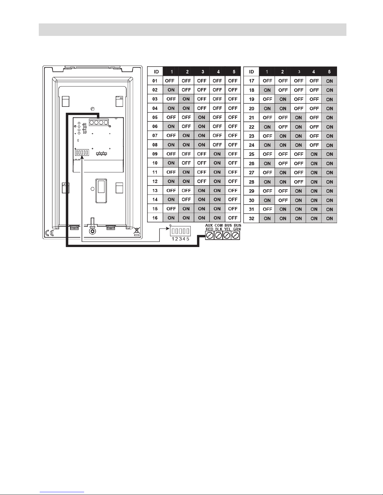
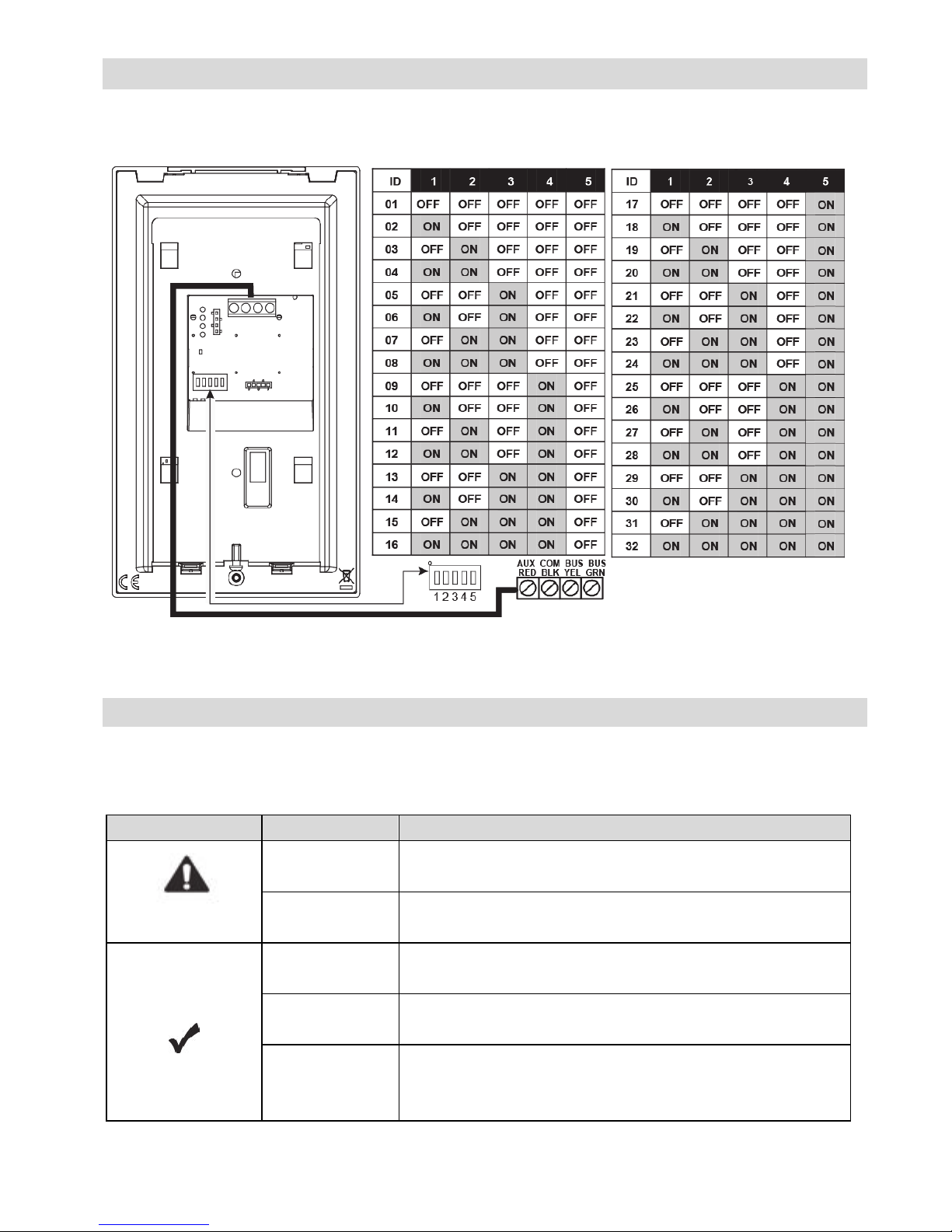
Keypad PCB
Use DIP switches 1 to 5 to define the BUS ID of each accessory / detector
according to the table in Figure 7.
Figure 7
6
Configuration
Visual Indicators
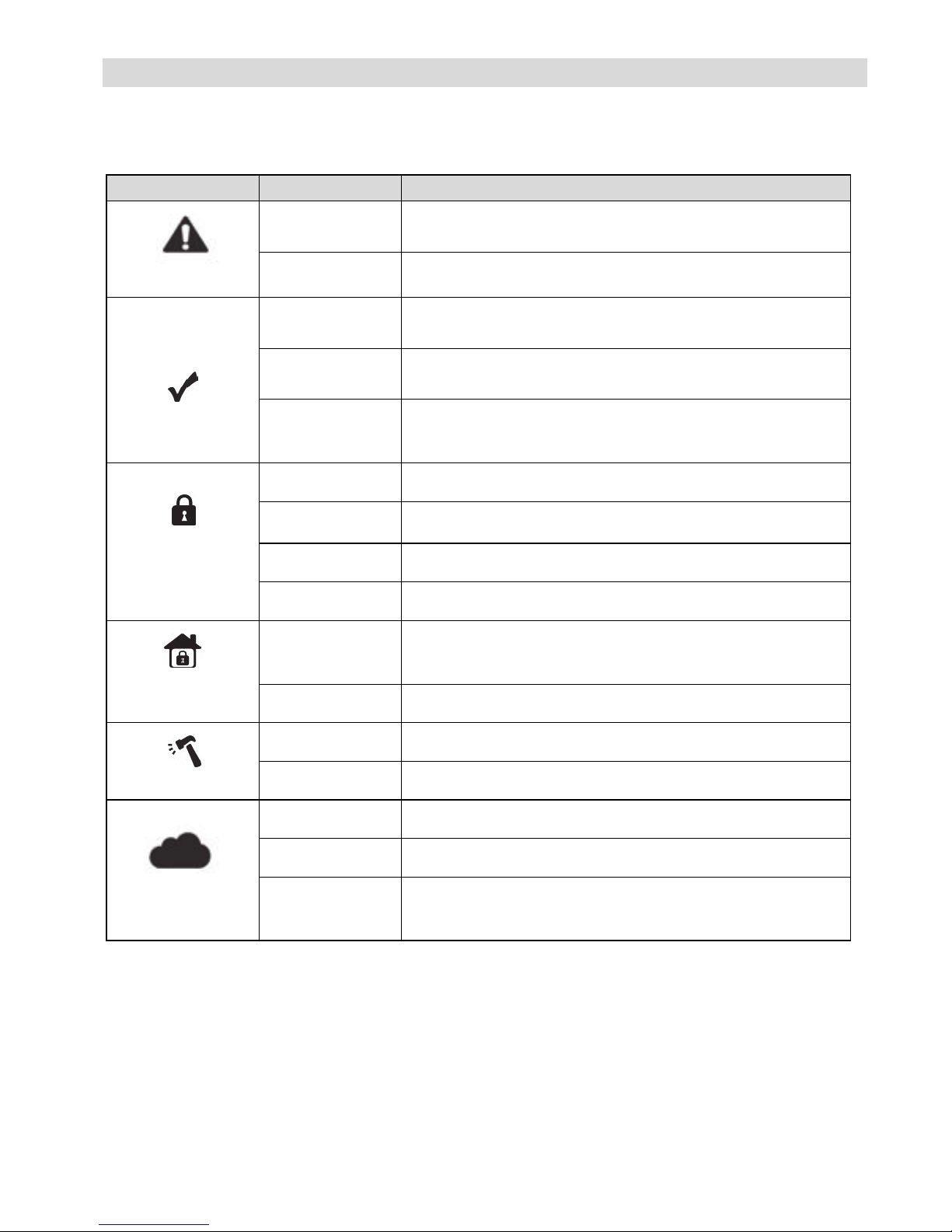
The following visual indicators are displayed on the LCD panel:
Icon Indication Operation
Trouble
On System trouble
Off System is operating normally
On System is ready to be armed
Off System is not ready to be armed
Slow Flash System is ready to be armed while exit/entry zone is
open
Arm / Alarm
On System is armed in Full Arm or Stay Arm mode
Off System is disarmed
Slow Flash System is in Exit Delay
Rapid Flash Alarm condition
Stay / Bypass
On System is Stay Arm mode (Part Set) or Zone Bypass
mode
Off No bypass zones in the system
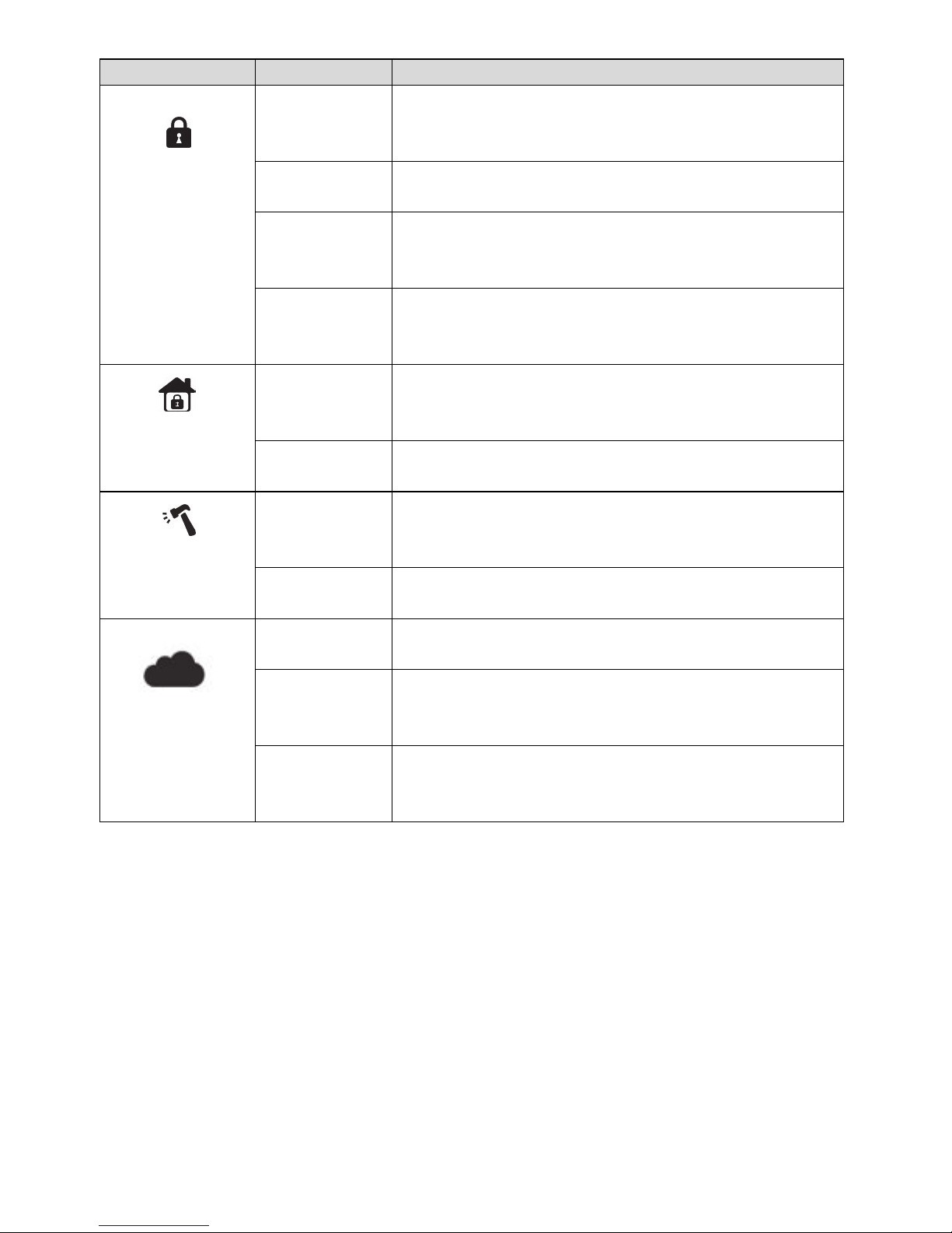
Tamper
On Zone/keypad/external module has been tampered
Off All zones are operating normally
Cloud
Connectivity
On System connected to cloud
Slow Flash Cloud connectivity trouble
Off No cloud connection configured / No cloud
connectivity
7
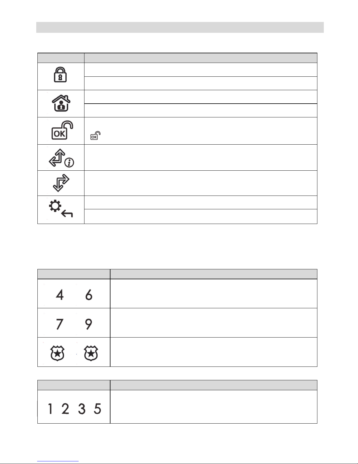
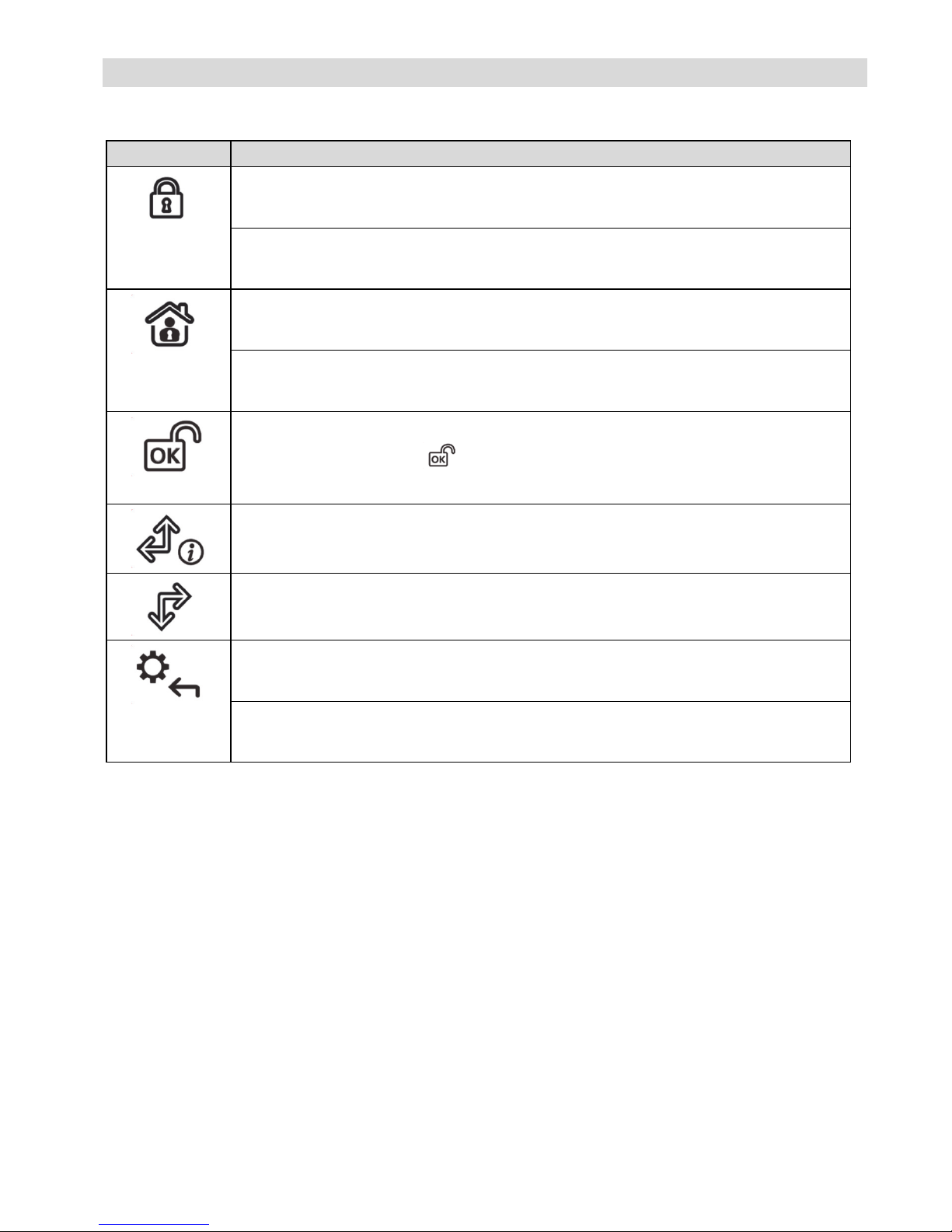
Keypad Keys
Control Keys
Key Operation
In Normal Operation mode: Used for Away (Full setting).
In User Functions menu: Used to change data.
In Normal Operation mode: Used for Stay arming (Part Setting).
In User Functions menu: Used to change data.
Used to disarm (unset) the system after a user code is entered;
is used to terminate commands and confirm data to be stored.
Used to scroll up a list or to move the cursor to the left;
Provides the system status.
Used to scroll down a list or to move the cursor to the right.
In Normal Operation mode: Used to enter the User Functions menu.
In User Functions menu: Used to move back one step in the menu.
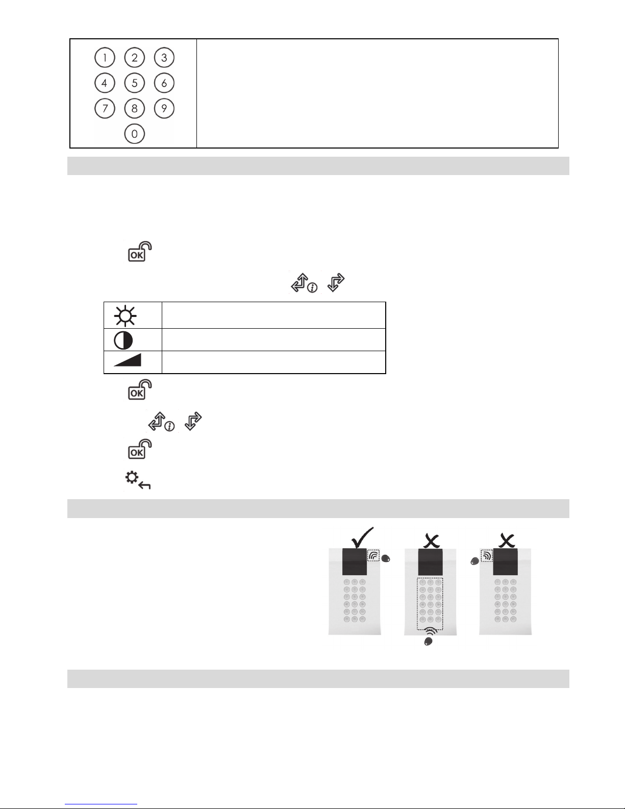
Emergency Keys
The following operations will send emergency notifications to the alarm
monitoring station
Key Operation
+
Pressing both keys simultaneously for at least two seconds
activates a Fire alarm
+
Pressing both keys simultaneously for at least two seconds
activates an Emergency alarm
+
Pressing both keys simultaneously for at least two seconds
activates a Police (Panic) alarm
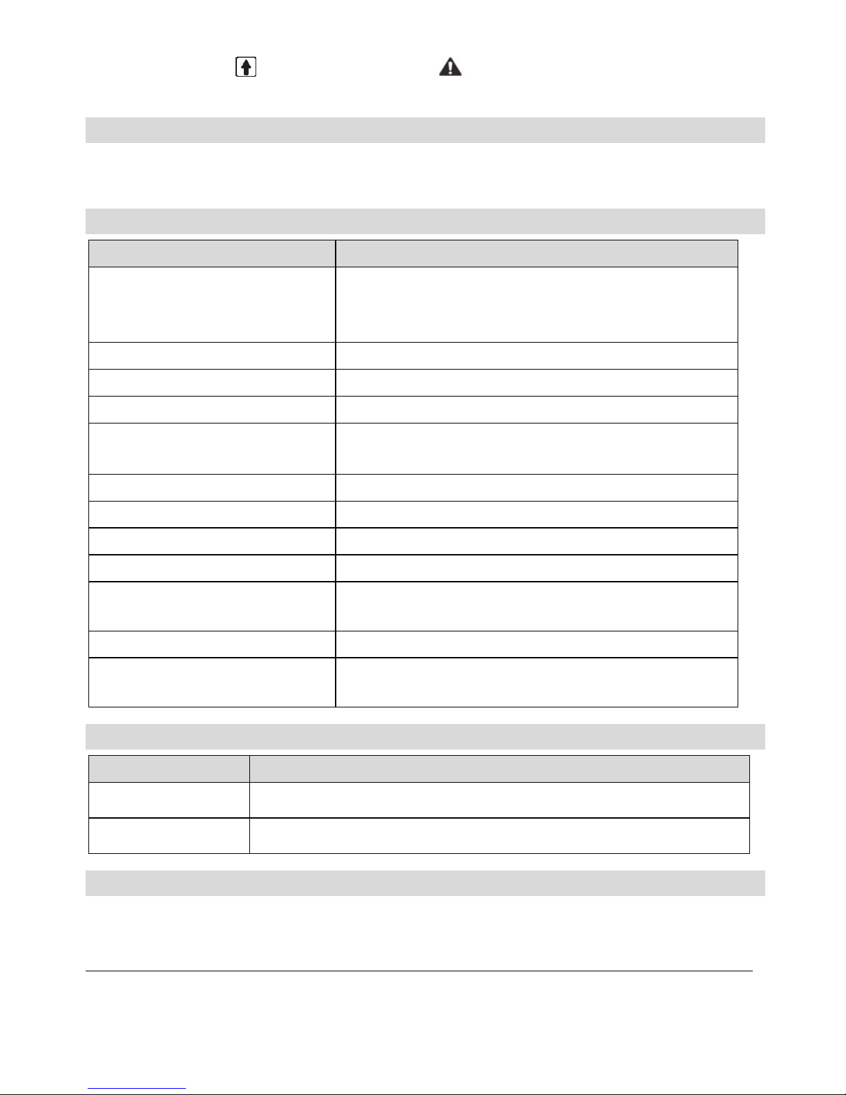
Function Keys
Key Operation
Used to arm (set) groups of zones (by default) or to activate a
prerecorded series of commands (macros).
To activate press for 2 seconds
/ / /
8
Numerical keys that are used to input numeric codes (arming,
disarming or used to activate specific functions)
Keypad Settings
Note: The following settings must be defined individually for each
keypad connected to the system.
To define keypad settings when idle follow this procedure:
1. Press for two seconds until the Keypad Settings menu appears
2. Select the relevant icon using the keys:
Brightness
Contrast
Keypad’s buzzer volume
3. Press .
4. Press the keys to adjust the level settings.
5. Press to save the adjustment.
6. Press to exit the keypad settings.
Proximity Tag Operation
Present the Proximity Tag to the
keypad (after waking the keypad) as
shown in the following illustrations:
Figure 8
Automatic Upgrade Resulting from Panel Manual Upgrade
Upon initiation of the LightSYS2 panel remote upgrade (See LightSYS2 Installer
Manual, Appendix I: Remote Software Upgrade), the keypad software may
automatically also be upgraded. During this approximately three-minute process
9
an upgrade icon ( ) and the power icon ( ) are displayed on the keypad and
the LED light flashes. Do not disconnect during this period.
Cleaning the Keypad
Use a non-abrasive damp cloth to clean the keypad. Do not expose the screen or
the keys directly to liquid.
Technical Specification
Parameter Description
Current Consumption:
RP432KPP2
RP432KP02
13.8v +/-10%, 130 mA typical/180 mA max.
Main Panel Connection 4-wire BUS, up to 300 m (1000 ft) from Main Panel
Proximity RF frequency: 13.56 MHz
Dimensions (H x W x D): 180 x 115 x 35 mm (7.1 x 4.5 x1.4″)
Weight: RP432KPP2: 295 gr.
RP432KP02: 287 gr.
Operating temperature: -10°C to 55°C (14°F to 131°F)
Storage temperature: -20°C to 60°C (-4°F to 140°F)
Humidity Range Average relative humidity: 75%
Standard Compliance EN50131-3 Grade 2 Environmental Class II
Min. number of variations of
PIN codes
10000 for 4-digit codes
Disallowed codes Codes from 0001 to 9999 are acceptable
Number of invalid code entries
before user interface is disabled
After 3 attempts
Ordering Information
Model Description
RP432KPP2 Panda Wired LCD Keypad, Proximity
RP432KP02 Panda Wired LCD Keypad
RED Compliance Statement
Hereby, RISCO Group declares that this equipment is in compliance with the essential
requirements and other relevant provisions of Directive 2014/53/EU. For the CE
Declaration of Conformity please refer to our website: www.riscogroup.com
10
Introduction
Les claviers LCD filaires avec ou sans lecteurs de proximités permettent une
utilisation simple et la programmation des systèmes de sécurité LightSYS
(version 5.63 et supérieures) et ProSYS Plus (version 1.2 et supérieures). Il est pris
en charge par le logiciel de configuration CS à partir de la version 3.1.0.0003.
Caractéristiques principales
• Lecteur de tags de proximité intégré en option
• Montage mural par vis
• Autoprotection à l'arrachement
• Design moderne
• Simple à installer grâce au support de fixation intégré
Installation
Fixation du clavier
Fixez le clavier au mur à l'aide du support de fixation fourni.
Pour fixer le clavier :
Figure 1 Figure 2
1. Séparez le support de fixation du clavier (voir Figure 1).
2. Faites passer les fils dans le trou du support de fixation (voir Figure 2).
3. Utilisez les trous de fixation comme gabarits et fixez le support de fixation au
mur à l'aide de 4 vis et d'une 1 vis supplémentaire pour l'autoprotection (voir
Figure 3)
FR
11
Figure 3
* Utilisée pour
l'autoprotection
Figure 4 Figure 5
4. Raccordez les fils au connecteur (AUX, COM et BUS) conformément à la
Figure 7.
5. Fixez le clavier au support de montage (voir Figure 4).
6. Insérez la vis de fixation pour fixer le clavier (voir Figure 5).
Fixation sur un boîtier électrique (en option)
1. Répétez les étapes 1 à 2 de la procédure précédente.
2. Fixez le support de fixation au boîtier électrique à l'aide de deux vis, comme
le montre la Figure 6.
Figure 6
3. Installez le clavier sur le support de fixation et insérez la vis de fixation pour
fixer le clavier.
12
PCB du clavier
Utilisez les commutateurs DIP 1 à 5 pour définir l'ID de bus de chaque
accessoire/détecteur en vous reportant au tableau de la Figure 7.
Figure 7
Configuration
Indicateurs visuels
Les indicateurs visuels suivants sont affichés sur l'écran LCD :
Icône Indicateu
r
Opération
Défaut
Allumé Il y a un défaut système
Éteint Le système fonctionne normalement
Allumé Le système est prêt pour l'armement
Éteint Le système n'est pas prêt pour l'armement
Clignotement
lent
Le système est prêt pour l'armement alors qu’une
zone de type Entrée / Sortie est ouverte
13
Icône Indicateu
r
Opération
Armement /
Alarme
Allumé Le système est armé en mode Armement Total ou
Armememnt partiel
Éteint Le système est désarmé
Clignotement
lent
Le système est en mode Temporisation de sortie
Clignotement
rapide
Il y a une condition d'alarme
Armement
partiel /
Exclusion
Allumé Le système est en mode Armement partiel ou zone
Exclue
Éteint Il n'existe aucune zone exclue dans le système
Autoprotection
Allumé La zone, le clavier ou le module externe est en
autoprotection
Éteint Toutes les zones fonctionnent normalement
Connectivité au
cloud
Allumé Le système est connecté au cloud
Clignotement
lent
Défaut de connexion au Cloud
Éteint Le connexion Cloud n’est pas configurée / Aucune
connexion au Cloud
14
Touches du clavier
Touches de commande
Touche Commande
En mode de fonctionnement normal : Cette touche permet d’armer
totalement le système.
Dans le menu Fonctions utilisateur : Cette touche permet de modifier les
données.
En mode de fonctionnement normal : Cette touche permet d’armer
partiellement le système.
Dans le menu Fonctions utilisateur : Cette touche permet de modifier les
données.
Cette touche permet de désarmer le système après la saisie du code
utilisateur ; la touche permet aussi de valider les commandes et de
confirmer les données à mémoriser.
Cette touche permet de faire défiler une liste vers le haut ou de déplacer
le curseur vers la gauche ; la touche indique aussi l'état du système.
Cette touche permet de faire défiler une liste vers le bas ou de déplacer le
curseur vers la droite.
En mode de fonctionnement normal : cette touche permet d'accéder au
menu Fonctions Utilisateur.
Dans le menu Fonctions utilisateur : cette touche permet de revenir à
l'étape précédente dans le menu.
 Loading...