

Risco RP432EW9 User Manual
usa@riscogroup.com
Relay 1 COM
Relay 2 COM
Power / Bus
Communication
Fail safe: Relay will change state while power is lost.
Power / Bus
in again.
32 Zone Wireless Receive 915
Model:RP432EW9
© RISCO Group 05/2018 5IN1424 G
Complies with: EN 50131-3; EN 50131-5-3
Grade 2 Class II 14 Hachoma st.
RISCO Group Contacting Info
RISCO Group is committed to customer service and product support. You can
contact us through our website (www.riscogroup.com) or at the following telephone
numbers:
UK Tel: 44-(0)-161-655-5500
support-uk@riscogroup.com
ITALY Tel: +39-02-66590054
support-it@riscogroup.com
SPAIN Tel: +34-91-490-2133
support-es@riscogroup.com
FRANCE Tel: +33-164-73-28-50
support-fr@riscogroup.com
RED Compliance Statement :
Hereby, RISCO Group declares that this equipment is in compliance with the essential
requirements and other relevant provisions of Directive 2014/53/EU. For the CE Declaration
of Conformity please refer to our website: www.riscogroup.com.
RISCO Group Limited Warranty
RISCO Group and its subsidiaries and affiliates ("Seller") warrants its products to
be free from defects in materials and workmanship under normal use for 24 months
from the date of production. Because Seller does not install or connect the product
and because the product may be used in conjunction with products not
manufactured by the Seller, Seller cannot guarantee the performance of the
security system which uses this product. Seller's obligation and liability under this
warranty is expressly limited to repairing and replacing, at Seller's option, within a
reasonable time after the date of delivery, any product not meeting the
specifications. Seller makes no other warranty, expressed or implied, and makes
no warranty of merchantability or of fitness for any particular purpose. In no case
shall seller be liable for any consequential or incidental damages for breach of this
or any other warranty, expressed or implied, or upon any other basis of liability
whatsoever.
Seller's obligation under this warranty shall not include any transportation charges
or costs of installation or any liability for direct, indirect, or consequential damages
or delay.
Seller does not represent that its product may not be compromised or
circumvented; that the product will prevent any personal injury or property loss by
burglary, robbery, fire or otherwise; or that the product will in all cases provide
adequate warning or protection. Buyer understands that a properly installed and
maintained alarm may only reduce the risk of burglary, robbery or fire without
warning, but is not insurance or a guarantee that such event will not occur or that
there will be no personal injury or property loss as a result thereof.
Consequently seller shall have no liability for any personal injury, property damage
or loss based on a claim that the product fails to give warning. However, if seller is
held liable, whether directly or indirectly, for any loss or damage arising under this
limited warranty or otherwise, regardless of cause or origin, seller's maximum
liability shall not exceed the purchase price of the product, which shall be complete
and exclusive remedy against seller.
No employee or representative of Seller is authorized to change this warranty in
any way or grant any other warranty.
CHINA (Shanghai) Tel:
+86-21-52-39-0066 supportcn@riscogroup.com
ISRAEL Tel: +972-3-963-7777
support@riscogroup.com
BELGIUM Tel: +32-25227622 supportbe@riscogroup.com
U.S.A Tel: +1-631-719-4400
support-
Rishon LeZion
ISRAEL
WARNING: This product should be tested at least once a week.
ENGLISH
Introduction
The LightSYS 2-Way Wireless Expander is a flexible unit that can be
used either as a wireless expander when connected to the LightSYS
security panel or as a stand-alone receiver, with support for up to 200
keyfobs and 2 outputs.
Main features
Support for RISCO’s range of 2-Way wireless sounders,
slim keypads, 8-button keyfobs and detectors Up to 4 2Way wireless slim keypads
Up to 32 supervised wireless zones (bus mode)
Up to 16 multi-function keyfobs (bus mode)
Up to 200 stand alone keyfobs (bus and stand-alone modes)
Two utility outputs
Rolling code technology
Signal jamming detection
Threshold-level calibration
Tamper detection
Transmitter supervision low battery detection
Nominal center frequency: 868.65MHz or 433.92MHz or 915MHz
Can be installed inside or outside the LightSYS main enclosure
Up to two WL Expanders per LightSYS system
Installation
The WL Expander can be mounted as a separate unit with its own
installation manual.
plastic housing or as PCB inside the LightSYS main
polycarbonate enclosure. For mounting the expander
inside the LightSYS enclosure refer to the LightSYS
Mounting considerations
When installed in its plastic housing: Do not install the WL Expander
close to metal objects and RF generating devices such as TV sets
or computers. Mount the expander at a height of at least 1.5 m (5 ft)
above the floor. Mount the expander relatively close and central to
the transmitter locations.
Wall Mounting
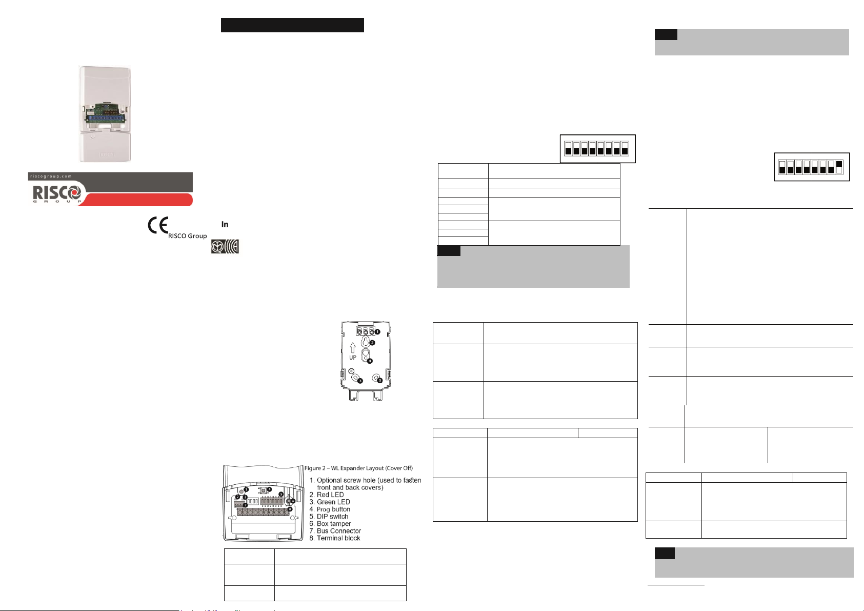
Figure 1 – Rear Panel
1. Screw cap
2. Upper mounting hole
3. Lower mounting holes (optional)
4. Wall tamper hole
1. Separate the mounting bracket from the main unit.
2. Use the mounting bracket as a marking template.
3. Tear off screw caps, as needed for covering front screw hole.
4. Mount the bracket to the wall.Wiring the WL Expander
Terminal
(left to right)
AUX Red
Com BLK Black 0V common. (In bus connection,
Description
+13.8V power VDC. (In bus connection,
3. Allocate the WL expander to the system (Programming menu
- Quick key [7 > 1 > 2 > 05]
Note:
I
4. Allocate the relay outputs of the expander as an output expander
(UO02) to the system (Programming menu - Quick key [7 > 1 > 2
> 03]
5. Calibrate the expander (Programming menu - Quick key [7 > 2 > 1])
6. Allocate wireless device (Programming menu - Quick key [7 > 2 >
2]) 7. Perform communication test between the expander and the
device
(Main menu > Maintenance> Wireless Test)
8. Set the WL device parameters (Zones: Quick key 2 > 1,
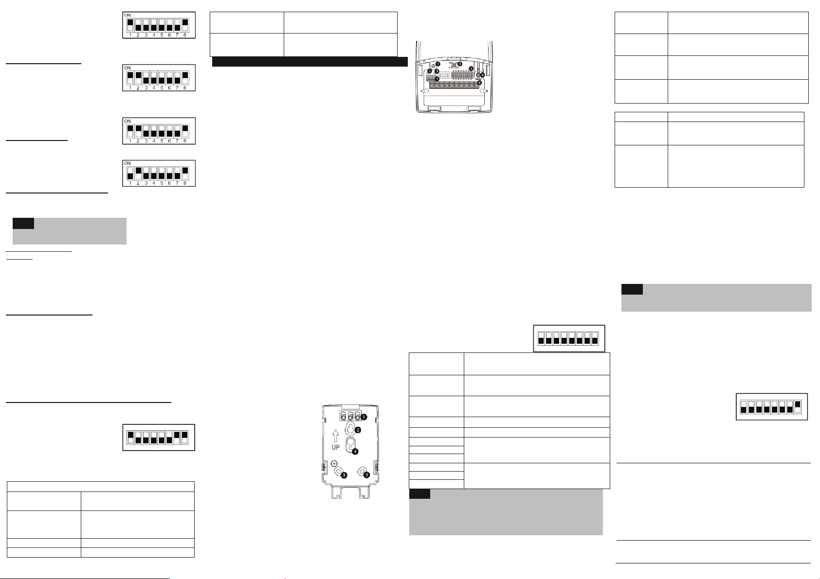
ON
12345678
BUS YEL Data bus connection (Not for SA mode)
BUS GRN
Relay 1 N.O.
Relay 1 N.C.
Relay 2 N.O.
Relay 2 N.C.
Notes:
1
2
Data bus connection (Not for SA mode)
12VDC @ 1A max Dry Contact Relays
12VDC @ 1A max Dry Contact Relays
regardless of the wiring gauge used.
Bus Mode
(SW8 in OFF position)
Keyfobs - Quick key 8 > 2) and the outputs parameters (Quick key
3)
Stand Alone Mode
(SW8 in ON position)
When the expander is set to Stand Alone mode it can support 200
keyfobs that can control its 2 outputs. Each output is controlled by a
dedicated button. Dipswitch Settings
SW1 + SW2
SW3
Dipswitch Settings
SW1- SW3
SW4 – SW6 Three switches to set ID of the output expander.
SW7
SW8
LEDs Indication
LED
(RED)
WL Comm
(GREEN)
Programming Steps in the LightSYS
The following instructions define the main programming steps for
performing wireless expansion to the LightSYS using the expander.
Two expanders can be allocated to the LightSYS. For full
programming instructions refer to the LightSYS full installation
manual.
1. Define the expander ID using switches [1]-[3]. The expander ID is
set to 1 by default
2. Define the output expander ID using switches [4]-[6]
Three switches to set ID of the WL Expander.
UO expander Enable/Disable
Off: Disable
On: Enable
Operational mod
Off: Bus mode
On: Stand-alone mode
Condition
Bus communication between the LightSYS and
the WL Expander
Steady: Bus Communication OK
Flash: In Prog Mode OR Bus Communication
Communication between a WL device and the
WL Expander
Steady: Bus Communication OK
Flash: Bus Communication trouble
Description
SW4
SW5
SW6
SW7 Changing output keys control in the keyfobs
SW8* Receiver mode
Leds Indication
LED
Communication
(RED)
WL Comm
(GREEN)
Programming
Note:
Enrolling Keyfobs
1. Set SW1 ON, SW2 OFF.
2. Press Prog button shortly. Red LED flashes slowly.
must be defined as Yes
ON
12345678
Receiver operation mode:
SW1 SW2 Mode
OFF OFF Normal mode
ON OFF Program mode
OFF ON
ON ON Delete keyfobs
Relay 1 / 2
Off: Relay 1
On: Relay 2
Used to define the Relays operation
Off: Pulsed
On: Latched
Setting pulse duration
Off: Pulsed counter is
off On: Pulsed counter
is on
Relay Fail secure / Relay fail safe
Off: Fail secure: Relay will not change state while power is
On:
Off: Changing UO process in disabled
On: Changing UO process in activated
Off: Bus mode
On: Stand alone mode
Condition
Receiver mode
Slow flash: Learn mode = assign device
Quick flash: Delete mode
One Pulse: Confirmation during program mode
Flash: In communication
Restore to manufacturer settings
lost
* Receiver mode
changes only after
powering the receiver
Description
Normal mode
-alone mode, unplug the
-
3. Press the keyfobkey. Green
LED lights steadily for confirmation.
4. Repeat steps 2-3 to assign
additional keyfobs.
5. Press Prog to exit this mode.
Deleting A Single Keyfob
1. Set SW1 and SW2 ON.
2. Press Prog button shortly. Red
LED flashes slowly.
3. Press the keyfobkey. The Green
LED lights steadily for
confirmation.
4. Repeat steps 2-3 to delete
additional keyfobs.
Deleting All Keyfobs
1. Set SW1 and SW2 ON.
2. Press Prog button for 5 seconds.
Red LED lights steadily.
3. When finished, Green LED lights
steadily for confirmation.
Restoring to manufacturer default
1. Set SW1 OFF, SW2 ON.
2. Press Prog button shortly. Red LED flashes slowly.
3. When finished, green LED lights steadily for confirmation.
Note:
Setting Relay Pulsed /
Latched 1. Set SW1 ON, SW2
OFF.
2. Using SW3 select relay 1 (OFF) or relay 2 (ON).
3. Using SW4 select latched (ON) or pulsed (OFF).
4. Press Prog button for 5 seconds to change relay status. Green
LED lights steadily for confirmation.
5. Repeat steps 2-4 for the second relay.
Setting Relay Pulse Duration
1. Set SW1 ON, SW2 OFF.
2. Using SW3 select relay 1 (OFF) or relay 2 (ON).
3. Set SW4 OFF (pulsed).
4. Set SW5 ON. The system is ready to start a counter for a pulse
(5 minutes maximum).
5. Press Prog button to start the timer. Red LED flashes slowly. 6.
Press Prog button again to stop the timer. Green LED lights
steadily for confirmation.
7. Set SW5 Off.
8. Repeat steps 4-7 for the other relay.
Changing Buttons for Outputs on the 4-Button Keyfob By default,
button 3 (small round key) of the keyfob controls output 1 and button 4
(egg shape) controls output 2. This can be changed for all the keyfobs
that are already assigned to the WL Expander.
1. Set SW1 ON, SW2 OFF.
2. Set SW7 On.
3. Press Prog button for 5 seconds.
Red LED lights steadily.
4. This will replace button 3 to button 1 and button 4 to button 2.
Green LED lights steadily for confirmation.
5. Set SW7 Off.
Technical specification
Operating Voltage:
13V +/- 10%
Current consumption:
Typical: 40 mA; max 65mA
RF immunity:
Range (L.O.S):
300 meters
Relay outputs:
12VDC @ 1A max Dry Contact Relays
Operating temperature:
Storage temperature:
-20°C to 60°C (-4°F to 140°F)
Size:
(4.94 X 3.07 X 1 inch)
Frequency:
RP432EW8 – 868.65 MHz
RP432EW4 – 433.92 MHz
RP432EW9 – 915 MHz
ITALIANO
Introduzione
L’espansione radio bidirezionale LightSYS è una unità che può
essere utilizzata come un modulo di espansione radio su bus della
centrale LightSYS o come ricevitore radio stand-alone, ideale per il
controllo di passi carrai in aree di parcheggio. Utilizzata come
ricevitore radio stand alone supporta fino a 200 telecomandi e 2
uscite.
Caratteristiche principali
Supporta la gamma di accessori radio bidirezionali RISCO come
sirene, tastiere a LED e telecomandi 8 tasti. Fino a 4 tastiere
radio bidirezionali a LED
Fino a 32 zone radio supervisionate (modalità bus)
Fino a 16 telecomandi a 4 tasti (modalità bus)
Fino a 200 telecomandi indipendenti (modalità bus e stand-
alone)
Due uscite di utilità
Tecnologia “Rolling code”
Rilevazione segnali RF di interferenza
Calibrazione livello soglia di rumore RF
Rilevazione manomissione
Rilevazione batteria scarica dei trasmettitori memorizzati
Frequenza di funzionamento: 868.65 MHz o 433.92 MHz o 915MHz
Può essere installata sia all’interno del contenitore della
centrale
LightSys che all’esterno tramite il suo contenitore in plastica
Fino a due espansioni radio per sistema LightSYS
Installazione
L’espansione radio bidirezionale può essere montata sia come unità
separata con un suo contenitore in plastica sia come scheda
elettronica all’interno del contenitore della centrale LightSYS. Per
montare l’espansione all’interno della centrale, fare riferimento al
manuale di installazione e programmazione LightSYS.
Considerazioni di Montaggio
In caso di installazione nel suo contenitore in plastica: Non
installare l’espansione radio vicino a oggetti metallici e dispositivi
che generano campi elettromagnetici come televisori o computer.
Montare l’espansione a un’altezza minima di 1,5 m da terra.
Montare l’espansione relativamente vicino e in posizione centrale
rispetto ai punti di installazione dei trasmettitori.
Montaggio a muro
Figura 1 – Base di fissaggio
1. Tappi per viti/fori
2. Foro di fissaggio superiore
3. Fori di fissaggio inferiori
(opzionali)
4. Foro per tamper antirimozione
1. Separare la base di fissaggio dall'unità principale.
2. Utilizzare la base di fissaggio come dima per segnare i fori da
effettuare.
3. Rimuovere i tappi per le viti necessari per coprire i fori della vite.
4. Montare la base alla parete.
Cablaggio del espansione radio
Figura 2 –
Schema dell’espansione radio
(senza coperchio)
1. Foro della vite
opzionale (utilizzato per
chiudere il coperchio
anteriore e posteriore)
2. LED rosso3. LED
verde 4. Pulsante Prog.
5. Microinterrutori
6. Tamper contenitore
7. Microinterruttori
8. Morsettiera
Morsettiera
(da sinistra a
destra)
AUX Rosso
COM BLK
BUS YEL
BUS GRN
Relè 1 N.O.
Relè 1 COM
Relè 1 N.C.
Relè 2 N.O.
Relè 2 COM
Relè 2 N.C.
Note:
1
2
Modalità BUS
(Microinterruttore 8 in posizione OFF)
Impostazione Microinterruttori (Micro)
Micro 1 - 3
Micro 4 – 6
Micro 7
Off: Disabilita
On: Abilita
Micro 8
Off: Modalità BUS
On: Modalità Stand-alone
Indicazioni dei LED
LED
Bus
Comm./POWER
(LED ROSSO)
WL Com.
(LED VERDE)
Passaggi di programmazione nella
LightSYS
Le seguenti istruzioni definiscono i passaggi principali di programmazione
per quanto riguarda la sezione radio di LightSYS utilizzando l’ espansione
radio bidirezionale. Alla centrale LightSYS possono essere assegnati fino a
due espansioni radio. Per le istruzioni complete di programmazione fare
riferimento al manuale di installazione e programmazione LightSYS. 1.
Definire l’indirizzo ID dell’ espansione utilizzando i microinterruttori
[1]-[3]. L’indirizzo dell’ espansione preimpostato di fabbrica è ID=1 2.
Definire l’indirizzo ID dell’espansione uscite utilizzando i
microinterruttori [4]-[6].
3. Memorizzare l’ espansione radio nel sistema (Menù di
Programmazione Tecnica - Tasti Rapidi [7 > 1 > 2 > 05]
Nota:
Se l’
4. Memorizzare le uscite a relè dell’ espansione come modulo di
espansione uscite (UO02) nel sistema (Menù di Programmazione
Tecnica - Tasti Rapidi [7 > 1 > 2 > 03]
5. Calibrare l’ espansione radio (Menù di Programmazione Tecnica -
Tasti Rapidi [7 > 2 > 1]
6. Memorizzare gli accessori radio (Menù di Programmazione Tecnica
- Tasti Rapidi [7 > 2 > 2]
7. Eseguire i test di comunicazione radio tra l’ espansione e gli
accessori radio (Menù Principale > manutenzione > Test Accessori
Radio) 8. Impostare i parametri degli accessori radio (Zone: Tasti
Rapidi 2 > 1, Telecomandi – tasti rapidi 8 > 2) ed i parametri delle
uscite a relè dell’espansione (tasti
rapidi 3)
Modalità Stand-Alone
(Microinterruttore 8 in posizione ON)
Quando l’espansione è impostato in modalità Stand-Alone diventa un
ricevitore che supporta 200 telecomandi che possono controllare le sue due
uscite. Ogni uscita è controllata da un tasto del telecomando.
Impostazione Microinterruttori (Micro)
Mic.1 + Mic.2
Micro
ricevitore
Micro
Modalità
OFF
OFF
Modalità normale
ON
OFF
Modalità Programmazione
OFF
ON
Riprist. impostazioni di fabbrica
ON
ON
Cancellazione telecomandi
Micro 3
Relè 1 / 2
Off:Relè 1
On: Relè 2
12345678
ON
12345678
ON
12345678
ON
 Loading...