

Risco RK825DTGL User Manual
iWISE
TM
Models: RK815DTGL
RK825DTGL
© RISCO Group 03/2017 5IN2635
Standard Limited Product Warranty (“Limit ed Warranty”)
RISCO L td. (“RISCO ") guarante e RISCO’s hardware pr oducts (“Pr oducts”) to
be free fr om defe cts in m aterials and wor kmanshi p when used and stored
under nor mal con ditions and in accordance with the instructions f or use
supplied by RISCO, for a period of (i) 24 months from the date o f deliver y of
the Prod uct (the “W arranty Peri od”). This Lim ited Warra nty covers the Product
only withi n the country wh ere the Product was ori ginally purchased and only
covers Pr oducts purchased as new.
Contact with cu stomers only. This Limi ted War ranty is solely for the b enefit
of custom ers who purchas ed the Products directly from RISCO or from a n
authorized distributor of RISCO. RISCO does not warrant the Product to
consumer s and nothing i n this Warranty obligates RISCO to accept Product
returns directly from end users who purch ased th e Produc ts for their own use
from RISC O’s custom er or from any installe r of RISCO, or otherwis e provide
warranty or other se rvices to an y such end user directl y. RISCO’s a uthorized
distributor or installer shall handle all inter actions with its end users in
connecti on with this Limited Warr anty. RISCO ’s authori zed distribu tor or
installer s hall make no w arranties, repres entations, guarantees or statements
to its end users or other t hird parti es that sugges t that RISCO has any
warranty or service obligation to, or any contractual privy with, any recipient
of a Product.
Remedi es. In the event that a m aterial d efect in a Product is disc overed and
reported to RISCO during the Warranty Pe riod, RISCO shall acc ept return of
the defecti ve Pro duct in accordance with the below RMA procedur e and, at
its option, either (i) repair or have repaired the defective Pr oduct, or
(ii) provide a replacemen t product to the c ustomer.
Return M aterial Authori zation. In the event that you need to return your
Product for repair or replacement, RISCO will pro vide you with a Return
Merchandise Aut horizati on Number (RMA#) as well as return instructions. Do
not return your Pr oduct without pri or approval from RISCO . Any Product
returned without a valid, unique RMA# will be refused and return ed to the
sender a t the sender ’s expense. T he return ed Product must be acc ompanied
with a d etailed descri ption of the defect disc overed (“De fect Descri ption”) and
must oth erwise follo w RISCO’s t hen-curren t RMA procedure published in
RISCO’s website at www.riscogroup.com in connection with any such r eturn.
If RISCO determi nes in its reasonable discretion that any Product returned
by customer conf orms to the ap plicable war ranty (“Non -Defective Product”),
RISCO will notify the cust omer of such determina tion and will return the
applicabl e Product t o customer at customer ’s expense. In addition,
RISCO m ay prop ose and assess customer a charge for testing and
examinati on of N on-Defective Pr oduct.
Entire L iability. T he repair or replacement of Pr oducts in accordance with
this Limit ed Warrant y shall be R ISCO’s entir e liability an d customer ’s sole
and exclusive remedy in case a materi al defec t in a Product is discovered
and repor ted as requi red herein . RISCO’s obligation an d this Limit ed
Warranty are contingent upon the full payment by customer for such Prod uct
and upon a proven weekly testing and examination of the Pr oduct
functionality.
Limitations. This Limited Warranty is the only warranty m ade by RISCO with
respect to the Pr oducts. T he warr anty is not transf erable to any thir d part y.
To the maxi mum extent permitted by applic able law, this Lim ited Warranty
shall not appl y and will be voi d if: (i) the conditi ons s et forth above are not
met (including, but not limited to, full payment by c ustomer for the Product
and a pro ven weekly testing and examina tion of t he Product functionality);
(ii) if the P roducts or any part or component thereof: (a) have been subjected
to improper oper ation or i nstallati on; (b) have been subjec t to negl ect, abuse,
willful dam age, abnor mal worki ng conditions , failure to follow RISCO ’s
instructions (whether oral or in writing); (c) have been misused, altered,
modified or repaired without RIS CO’s writte n approval or combined with,
or installed on products, or equipment of the customer or of any t hird party;
(d) have b een dama ged by any factor beyon d RISCO’s r easonabl e control
such as, but not limited to , power failure, electric power su rges, or unsuitable
third part y components and the i nteractio n of soft ware the rewith or (e) an y
failure or delay in the performance of the Product attribut able to any means
of communication provided by an y third p arty ser vice provider, including, but
not limited to, GS M interr uptions, l ack of or internet outage and/or telephony
failure. BATTERIES ARE EXPLIC ITLY EXCLUDED FRO M THE WARRANTY
AND RISC O SHALL NOT BE HELD RESPONSIBLE OR LIABLE IN
RELATIO N THERETO, AND THE ONLY WARRANTY AP PLICABLE
THERETO, IF ANY, IS THE BATT ERY M ANUFAC TURER'S WARRANTY.
RISCO d oes not inst all or integr ate the Prod uct in the e nd user’s se curity
system and is therefore not respo nsible for and cannot guarantee the
perform ance of the end user’s s ecurity syst em which us es the Pro duct or
which the Product is a componen t of.
This Limited Warr anty applies onl y to Products manufactured by o r for
RISCO. Further, t his Limi ted Warr anty does not apply to any soft ware
(including operati ng system) added to or provided with the Produc ts or an y
third-party software, even if packaged or s old with the RISCO Product.
Manufacturers, suppliers, or third parties other than RISC O may provide their
own warr anties, but RISCO , to the extent permitted by law and exc ept as
otherwis e specificall y set forth h erein, provi des its Prod ucts “AS IS”.
Software and applications distributed or m ade available b y RISCO in
conjuncti on with the Product (wit h or without the RISCO brand), i ncluding,
but not limited to system software , as well as P2P services or an y other
service m ade available by RISCO in relati on to th e Product, are n ot cover ed
under this Limite d Warranty. Refer to the T erms o f Service at:
https://ris cocloud.com/EL AS/Web UI/User Login/License for details of your
rights and obligati ons with respect to the use of such applic ations,
software or any s ervice. RISCO d oes not represe nt that the Product may not
be compromised or circumvented; that t he Product will prevent a ny pers onal
injury or property loss by burglar y, robber y, fire or otherwis e, or that the
Product will in all cases pr ovide adequate warning or protection. A properly
installed and mai ntained alarm may only r educe the risk of a burglary, r obbery
or fire wit hout warning, b ut it is not insurance or a guarantee that such will not
occur or will not c ause or l ead to personal injury o r property loss.
CONSEQ UENTLY, RISCO SHALL HAVE NO LIABILITY FOR AN Y
PERSON AL INJURY, PR OPERT Y DAMAGE O R OTHER LOSS BASED ON
ANY CLA IM AT ALL INCLUDING A CLAI M THAT THE PR ODUCT FAILED
TO GIVE W ARNING. EXCEPT FOR THE WARR ANTIES SET FORTH
HEREIN, RISCO AND IT S LICEN SORS H EREBY DISCLAIM ALL EXPRE SS,
IMPLIED OR STATUTORY, REPRESENTAT IONS, W ARRANTIES,
GUARANTEES, AND CO NDITIO NS WIT H REGARD TO THE PRODUCT S,
INCLUDING BUT NOT L IMITED T O ANY REPRE SENTATIONS,
WARRANTIES, GUARANTEES, AND CO NDITIONS OF
MERCHANTABILITY, FIT NESS FOR A PARTICU LAR PU RPOSE, TITL E
AND WARRANT IES AGA INST HIDDEN OR LAT ENT DEFECTS, TO THE
EXTENT PERMITTED BY LAW. W ITHOUT LIMIT ING THE GE NERALITY
OF THE FOREGOING, RISCO AND ITS LICENSO RS DO NOT
REPRESENT OR WARRANT THAT: (I) T HE OPERATION OR USE OF T HE
PRODUCT WILL BE TIMELY, SECURE, UNINTERRUPT ED OR
ERROR-FREE; (ii) T HAT ANY FILES, CONT ENT OR INFORMATIO N OF
ANY KIND THAT MAY BE ACCESSED T HROUG H THE PRODU CT SHALL
REMAIN SECURED OR NON DAMAGED. CUST OMER ACKNOW LEDG ES
THAT NEITHER RISCO NOR IT S LICENSORS CONTR OL THE TRANSFER
OF DATA OVER COMMUN ICATIONS FACILITIES, INCLUDING THE
INTERNET, GS M OR OT HER ME ANS OF COMMUNICATIONS AND THAT
RISCO’S PRODUCT S, MAY BE SUBJECT TO LIMITAT IONS, DEL AYS, AND
OTHER PROBLE MS INH ERENT IN THE USE OF SUCH MEANS OF
COMMUN ICATIO NS. RISCO IS NOT RESPONSIBLE FOR ANY DELAYS,
DELIVERY FAILU RES, OR OTHER DA MAGE R ESULT ING FRO M SUCH
PROBLE MS. RISC O WARRANTS THAT ITS PRODUCT S DO NOT, TO THE
BEST OF ITS KN OWLED GE, INFRINGE UPON ANY PATENT, COPYRIGHT,
TRADEMARK, T RADE SECRET OR OTHER INT ELLECT UAL PR OPERT Y
RIGHT IN ANY EVENT RISCO SHALL NO T BE LIABLE FOR ANY
AMOUNT S REPR ESENT ING LOST REV ENUES OR PR OFITS, PUNITIV E
DAMAGES, OR F OR AN Y OTHER INDIR ECT, SPECIAL, INCIDENTAL, OR
CONSEQ UENTIAL DAMAGES, EVEN IF THEY W ERE FORESEEABLE OR
RISCO HAS BEEN INFOR MED O F THEI R POT ENTIAL.
ENGLISH
iWISE RK815DTGL/RK825DTGL detectors are the ultimate
motion detectors for professional installations, incorporating Anti-Cloak
Technology (ACTTM), adhering to new environmentally friendly guidelines.
RK815DTGL/R K825DTGL detectors are available in 1 0m,
15m and 25m models, and include built -in end-of-line (EOL) resistors to
simplify installation.
Installation / M aintenance
1. Mounting - The RK815DTGL/RK825DTGL can be
mounted either on a flat surface or on a wall corner (corner mounting).
• Using a suitable tool, open the following knockouts on the detector’ s
base (see Figure 1).
Note: Bac k tamper “ Breakabl e plate” not applicable in this vers ion.
2. To select the correct vertical adjustment position for wide angle lens,
use the sc ale on the bottom left hand side of the PCB as follows:
Mounting height and scale position based on room size:
Mounting Height L - LONG S - SHORT
For RK815DTGL
2.1m-2.7m (6'11"-8’ 10")
For RK825DTGL
1.8m-2.0m (5'11"-6’ 7") 25m (82 ’) 8m (26’ )
Note: For Corridor in stallations , select pos ition to ”L” and moun t the
detect or at 2.5m/8’ 2” height.
3. Set jumpers (see Jumper Setting section).
Note: R eset the detector after each change made to the settings.
4. Install the front cover back to its place (in a revers e sequence of
the removal.
5. Perform a Walk test (see W alk Test section).
6. Changing Lenses (see Figure 2).
Terminal Wiring (Figure 5)
Terminal Description
- 12 + 12VDC Input
ALARM N.C. Relay
TAMPER N.C. Tamper switch
FAULT/AM
LED
**Activation Signal-
If 12VDC is applied, and the LED/SET Input Jumper is on 12V position
0V is applied and LED/SET Input Jumper is on 0V position
Jumper Settings
Jumper Function
SW1-1: LED
ON
(Default)
OFF
SW1-2: ACT
ON
OFF
(Default)
SW1-3: Green Line
The RK815DTGL/RK825DTGL includes a Green Line featur e
that follows en vironmental guidelines by avoidin g surplus emission.
ON
OFF
(Default)
SW1-4: Self
Test
J1 - Alarm EOL
J2 - Tamp er EOL
J4 - LED/SET
INPUT
15m (50 ’) 6m (20’ )
Not applicable in this version.
LED operation remote control
When an ”A ctivation S ignal”** is applied to the LED
input terminal, all LEDs will be disabled.
LEDs are enabled if nothing is connected (unless LED
jumper is OFF) or 0V/12V is applied (according to the
LED/SET Input Jumper position, 12V or 0V).
- Or -
Used to determine the operation of the d etector’s LEDs
LEDs are enabled, allowing LED control via the LED
input terminal.
LEDs are disabled
Used to determine if ACT mode is enabled or disabled
ACT Enabled
Important: D o not use A CT™ mod e if you ar e
expecting that there will be moving objects outside the
required protected area, a corridor for example.
ACT Disabled.
Green Line feature is enabled: To deacti vate the MW
module, the LE Ds must be r emotely disabled b y the
LED terminal.
Note: W hen ‘Gr een Line’ is on (Microw ave off), th e
detector will still activate (PIR only)
Green Line feature in disabl ed: MW is constantly in
use.
Not applicable in this version.
Jumpers J1 and J2 allow the selection of Tamper
and Alarm resistance (1K, 2.2K, 4.7K, 5.6K, 6.8K)
accordin g to the control panel (see Figur e 3).
Follow the terminal block connection diagram in
Figure 3 when connecting the detector to a
Double End Of Line (DEOL) Zone.
Used to determine the polarity of the external input.
See Terminal W iring section, LED Terminal
Jumper Function
TM
Walk Test
1. Two min utes after applying power (warm-up p eriod), walk test the
2. The MW range can be adjusted by using the potentiometer located
MW range adjustment (Figure 4)
LEDs Di splay
Technic al Spe cification
See Terminal W iring section, LED Terminal
Detector over the entire protected area to verify proper operation of
the unit (see Figure 6).
on the PCB. It is important to set the potentiometer to the lowest
possible setting that will still provide enough coverage for th e inner
boundary protected area (s ee Figure 4).
1 Over power
2 Under power
3 Correct adjustment
LED State Description
Yellow
Green On MW detection
Red
All LEDs
Electrical
Current consumption 16mA at 12VDC (Typical)
Voltage requirements 9 -16VDC***
Alarm contacts 24VDC, 0.1A
Tamper contacts 24VDC, 0.1A
Environmental
RF immunity According to EN50130-4
Operating temperature 0°C to 49°C (14°F to 131°F)
Storage temperature -20°C to 60°C (-4°F to 140°F)
Optical
Filtering White Light Protection
Physical
Size 127.6 x 64.2 x 46.6 mm (5 x 2.5 x 1.84 in.)
Weight 120 gr. (4.2 oz.)
*** Power to be supplied by 5A max. pow er source using safety
approved wires, with a min G auge of 20AW G.
A Detector
B Corridor
On PIR detection
Flashing Trouble in PIR channel
Flashing Trouble in MW channel
On ALARM
Flashing
(consecutively)
At power-up, the LEDs will flash
consecutively until the end of the warmup period (2-3 minut es).
41mA at 12VDC (max.)
FRANÇAIS
Les détecteurs iWISE RK815DTGL/RK825DTGL sont
les tout derniers mod èles de détecteurs de mou vement conçus pour
établissements professionnels. Ils intègrent la technologie de
l'Anti-C loak™ (AC T™), répo ndant aux n ouvelles d irectives d e
protection de l'environnement.
Disponibles en modèles 10m, 15m et 25 m, les détecteurs iWISE
RK815DTGL/R K825DTGLc omprennent des résistanc es
de Fin de ligne (EOL = end-of-line) intégrées qui facilitent l'installation.
Installation
1. Montage – RK815DTGL/RK825DTGL peut être installé
soit sur une surface plane s oit en coin (gauche ou droit).
• A l’aide d’un outil adequat, ouvrez les pastilles pré-perc ées
correspondant es sur la báse du dé tecteur (cf. Figure 1).
Remarque: Retour falsification "cassabl e plaque" pas applicable
dans cette version.
2. Pour définir le bon r églage vertical, positionnez l'appareil en
LENTILLE GRAND ANGLE. Servez-vous de l'échelle figurant sur le
côté inférieur gauche de la carte PCB (cf. Figure 6) comme suit:
Hauteur de montage et position selon la taille de la pièce:
Hauteur de montage L - LONG C - COURT (SHORT)
Pour RK815DT GL
2,1m-2,7m (6'11"-8’ 10") 15m (50 ’) 6m (20’)
Pour RK825DT GL:
1.8m-2,0m (5'11"-6’ 7") 25m (82’) 8m (26’)
Remarque: Pour les installations en couloir, sélectionnez la position
“L” et appliquez l'option de montage à hauteur de 2,5m/ 8’2”.
3. Réglez les cavaliers (cf. § Réglage des cavaliers).
4. Replac ez le couvercle frontal (en inversant pour cela l'ordre des
étapes d e la procédure de retr ait).
5. Exécutez un test de passage (cf. § Test de passage).
6. Changement des lentilles (cf. Figure 2).
Câblage des T erminaux (cf. Figure 5)
Terminal Description
- 12 + Entrée 1 2VCC
ALARM Relais N.F., 24VCC, 0,1A
TAMPER Relais N.F., 24VCC, 0,1A
MIN MAX
Terminal Description
FAULT / AM
LED
**Signal d'Activation-
Si une tension de 12VCC est appliquée et que le Cavalier d'entrée
LED/SET est en position 12V
Si la Terre (GND) est reliée, le Cavalier d'entrée LED/SET est en
position 0V.
Réglage des c avaliers
Cavalier Fonction
SW1-1: LED
Marche (ON)
(Défaut)
Arrêt (OFF)
SW1-2: ACT Définit si le mode ACT est activé ou non
Marche (ON)
Arrêt (OFF)
(Défaut)
SW1-3: Green Line
RK815DTGL/R K825DTGL compr end une caractéristique
‘Green Line’, conc ept qui per met aux dét ecteurs d e respecter les
directives environnementales en évitant les émissions excessives.
Marche (ON)
Arrêt (OFF)
(Défaut)
SW1-4:
J1 - Alarm EOL
J2 - Tamper EOL
J4 - Entrée
LED/SET
Test de passage
1. Deux minutes après avoir réalisé la mise sous tension (séquence
d'échauffement), effectuez un test de passage pour vérifier l'efficacité
du détecteur sur la totalité d e la zone à protéger.
2. Assurez-vous d'avoir bien réinstallé le couvercle frontal avant de
mettre le détecteur sous tension (cf. Figure 6).
3.Le potentiomètre situé sur la carte PCB permet de régler la portée de
détection hyperfréquence. Il est important de régler le potentiomètre
sur le niveau le plus bas possible qui fournira cependant une couverture
suffisante sur la totalité de la zone à protéger.
Réglage de la portée HF (cf. Figure 4)
1 Trop puissant
2 Pas assez puissant
3 Réglage corr ect
Affichage LED
LED Position Signification
Jaune
Verte Allumée (ON) Détection HF (hyp erfréquence)
Rouge
Toutes
diodes LED
Non applicable dans cette version.
Contrôle à distance des indicateurs LED
Lorsqu' un ”Signal d 'Activation ”** est appl iqué à
l'entrée LED du bloc des terminaux ou bornes d e
connexi on, les indicateurs LED se désactivent
(cf. aussi l'entr ée Test automatique dans le
tableau consacré au Réglage des cavaliers).
Les voyants LE D sont activés si rien n'est relié
(sauf si le cavalier LED est éteint (OFF).
Définit le fonctionnement des indic ateurs LED du
détecteur.
L'activation des indicateurs LED dépend du
paramétrage du contrôle à distanc e de leur
fonctionnement (cf. § Câblage des Terminaux, borne
de connexion LED).
Les indicateurs LED sont désactivés.
ACT activé.
Important! N 'utilisez pas le mode ACT™ dans une
zone en dehors de laquelle le pass age d'objets
en mouvement vous paraît logique et att endu, u n
couloir p ar exemple.
ACT désactivé.
"Green Line" activée: Pour désactiver le module HF
pendant les périodes d'inactivité, les indicateurs LED
doivent être désactivés à distance.
Green Line dés activé (OFF): le canal HF est
constamment activé.
Non applicable dans cette version.
Les cavaliers J1, J2 permettent de sélectionner
les résistances EOL (fin de ligne)
d'Autoprotection, Alarme et FAULT /AM (1K,
2,2K, 4,7K, 5,6K, 6,8K et 12K) en f onction de la
centrale (cf. Figure 3 ci-dessous).
Suivez les indications du diagramme de c onnexion
du bloc des terminaux de la Figure 3 pour relier le
détecteur à un e zone EOL Double (DEOL).
Détermine la polarité de l'entrée externe.
Cf. § Câblage des Terminaux, bornes de connexion
LED (Mise en service).
Cf. § Câblage des Terminaux, bornes de connexion
LED (Mise en service).
A Détect eur
B Couloir
Allumée (ON) Détection IRP
Clignotante Panne de canal IRP
Clignotante Panne de canal HF
Allumée (ON) Indique une ALARME
Clignotante
(l'une après
l'autre)
Lors de la mise sous tension, les
diodes L ED clignotent de manière
ininterrompue, l'une après l'autre,
jusqu'à la fin d e la séquenc e
d'échauffement (2 à 3 minutes).
Spécifications techniques
Electriques
Consom mation électrique 14.8 mA à 12VCC (en utilisation
Tension requis e 9 -16VCC
Contacts d'alarme 24VCC, 0,1A
Temps minimal de changement d’ét at: 2.2 seconds
Contacts d'aut oprotection 24VCC, 0,1A
-Ou-
MIN MAX
Rétsistance de la boucle de Détection: Etat ouvert: plus que 10
Ondulations résiduell es maximales
admissibles:
Environnementales
Immunité RF Selon EN50130-4
Tempér ature de fonctionnement D e 0ºC à 49ºC (14ºF à 131ºF)
Tempér ature de stockage De -20ºC à 60ºC (-4ºF à 140ºF)
Indice d e protection: IP 31/IK 02
Taille du càble à utiliser:
Optique s
Filtrage Protection anti-lumière blanche
Physiques
Dimensions
Poids 120g
Organisme de certification
AFNOR CERTIFICAT ION: 11 rue Francis de Pr essens é
93571 LA PLAINE SAINT-DENIS Cedex, http://www.marque-nf.com
CNPP: BP 2265, 27950 ST MARCEL, http://www.cnpp.com
ESPAÑOL
Los detectores RK815DTGL/RK825DTGL son la última
palabra en detectores de movimiento para instalaciones profesionales,
incorporando la tecnología Anti-Cloak ™ (ACT™), adhiriéndos e a las
nuevas directrices respetuosas con el medioambiente.
Los detectores RK815DTGL/RK825DTGL están disponibles
en versiones de 10m, 15m y 25m, e incluyen resistencias incorporadas
de final de línea (EOL) para simplificar la instalación.
Instalación / M antenimiento
1. Montaje - El RK815DTGL/RK825DTGL puede montarse
en una superficie plana o en un rincón de pared (montaje en rincón).
• Usando una herramient a apropiada, abra los siguientes agujeros
pre-marcados en la base del detector (ver Figura 1).
Nota: Volver manipulaciones "rompi ble plac a" no se aplica en esta
versión.
2. Para selecccionar la posición correcta de ajuste vertical para lentes
gran angular utilice la escala en el lado izquierdo del P CB, según
se indica:
Altura d e montaje y posición de la esc ala se gún el tamaño de
la habitación:
Altura d e Montaje L - LONG S - SHORT
Para RK 815DTGL
2.1m-2.7m (6'11"-8’ 10") 15m (50’) 6 m (20’)
Para RK 825DTGL
1.8m-2.0m (5'11"-6’ 7")
Para ins talaciones de Pasillo, seleccion e la posici ón “L” e
Nota:
instale a 2.5m/8’2” de altura.
3. Configure los puentes (véase la sección Configuración de Puentes).
Reinicie el detector d espués de que se haga un cambio en las
Nota:
configur aciones.
4. Coloque de nuevo la tapa delantera en su lugar (de modo invers o
al de retir arla)
5. Realic e una prueba de Movimiento (véase la sección Prueba de
Movimiento).
6. Cambiando las Lentes (ver Figura 2).
Cableado del Terminal (ver Figura 5)
Terminal Descripción
- 12 +
Entrada de 12VCC
ALARM Relé N.C.
TAMPER Conmutador del Tamper N.C.
FAULT/AM
No se aplica en esta versión.
(Fallo/AM)
Control remoto del funcionamiento del LED
LED
Cuando se aplica una ”S eñal de Activac ión”** al terminal
de entrada del LED, se desactivan todos los LEDs.
Los LEDs se activan si no hay nada conectado (a menos
que el puente del LED esté en OFF) o se aplican 0V/12V
(según la posición del Puente LED/SETInput, 12V ó 0V)
**Señal de Activación-
Si se aplican 12VCC, y el puente (jumper) LED/S ET INPUT está en la
posición 12V
Se aplican 0V y el puente (jumper) LED/SET INPUT está en la posición 0V.
typique)
39.5 mA à 12VCC (max. avec
tous les voyants LED allumés)
Etat fermé: moins que 18ohm
0.25 créte à créte
Fil de diamétre au moins 0.5 mm
pour une longueur ne dépassant
pas 300 métres
127.6 x 64.2 x 46.6 mm
(5 x2.5 x 1.84 in.)
25m (50 ’) 8m (26’)
- O -
Configuración de los Puentes
Puente Función
SW1-1: LED
SW1-2: ACT
SW1-3: Green Line
El RK815DTGL/RK825DTGL incluye una característica
Green Line que sigue las directivas medioambientales evitando un
exceso de emisión.
SW1-4: SELF
J1 - Alarm EOL
J2 - Tamp er EOL
EOL (Fin de Línea)
J4 - LED/SET
(ENTRADA
LED/SET)
Prueba de Movimiento
1. Dos minutos d espués de la puesta en marcha (periodo de
2. El rango de MW puede ajustarse mediante el potenciómetro situado
Ajuste del Rango de MW (véase Figur a 4)
Visualiz ación de los LEDs
Especificaciones Técnicas
Eléctricas
Consumo de c orrient e 16mA a 12VCC (T ípico)
Requisitos de voltaje 9 -16VCC
Contact os de Alarma 24VCC, 0.1A
Contact os de T amper 24VCC, 0.1A
Ambientales
Inmunidad a RF Según E N50130-4
Temper atura de funcionami ento 0ºC a 49ºC (14°F a 131°F)
Temper atura de almacenamiento -20ºC a 60ºC (-4°F a 140°F)
Óptica
Filtrado Protección contra luz blanc a
Físicas
Tamaño
Peso 120 gr. (4.2 oz.)
Usado para determin ar el funcionamient o de los LEDs
del detector.
ON
Los LEDs están habilitados, permitiendo el control del
(Predeterm.)
LED a través del terminal de entrada del LED
Los LEDs están deshabilitados.
OFF
Usado para determin ar si el modo ACT está habilitado
o deshabilitado
ACT Habilitado
Importante: N o use el m odo ACT™ si usted es pera
ON
que haya objetos en movimiento fuera d el área
protegida requerida, p.ej. un pasillo.
OFF
ACT Deshabilitado.
(Predeterm.)
La característica Green Line está habilitada: Para
ON
desactivar el módulo de MW , los LEDs deben
deshabilitarse remotamente mediante el terminal LED.
NOTA: Cuan do ‘Green Line’ está activado (MW
desactivado), el detector aún se activará (sólo PIR).
La característica Green Line está deshabilitada: el
OFF
MW est á constantemente en uso
(Predeterm.)
Usado para testar las tecnologías de detección.
TEST
(Auto Test)
INPUT
calentamiento), haga la prueba de movimi ento al detector en toda el
área protegida para verificar el corr ecto funcionamiento de la unidad
(véase Figura 6).
en el PC B (placa de circuito impreso). Es importante ajustar el
potenciómetro a la c onfigur ación más baja posible que aún pueda
proporcionar suficiente cobertura al límit e interno del área pr otegida.
1 Energí a excesiva
2 Energí a baja
3 Ajuste correcto
LED Estado Descripción
Amarillo
Verde
Rojo Encendido ALAR MA
Todos los LE Ds
Los puentes J1 y J2 permit en la s elección de la
resistencia del Tamper y de la Alarma (1K, 2.2K,
4.7K, 5.6K, 6.8K) según el panel de control
Siga el diagrama de conexión del bloque de
terminales de la Figura 3 cuando c onecte el
detector a una Zona de Doble Fin-de-Línea
(DEOL).
Usado para determin ar la polaridad de la entrada
externa.
Véase la sección Cableado del Terminal, Terminal
LED
Véase la sección Cableado del Terminal, Terminal
LED
A Detect or
B Pasillo
Encendido Detección PIR
Parpadeando Problema en el canal PIR
Encendido Detección MW
Parpadeando Problema en el canal MW
Parpadeando
(sucesivamente)
Al poner en marcha, los LEDs
parpadearán consecutivamente
hasta el final d el periodo de
calentamiento (2-3 minutos).
41mA a 12VCC (Máx.)
127.6 x 64.2 x 46.6 mm
(5 x 2.5 x 1.84 pul)
MIN MAX
(Factory Settings)
Feet
RL17 (Corridor)
30
6
20
4
Feet
10
10
2
2
30
ITALIANO
I rivelatori iWISE RK815DTGL/RK825DT GLsono rivelatori
di movimento che integrano le tecnologie più avanzate per l e installazioni
profess ionali. Qu esti rivelatori includono la tecnolo gia (ACT™) e la
funzion e Green Li ne per evit are emissi oni superfl ue nell’ambi ente.
iRK815DTGL/RK825DTGL sono disponibili nei mod elli 10,
15 e 25 metri ed hanno le r esistenze di fine linea integrate nel circuito
per sem plificarne al massim o l’installazi one.
Installazione / Manutenzione
1. Installazione - RK815DTGL/RK825DTGL può essere
installato sia su di una superficie piana che ad angolo.
• Utilizzando uno strumento appr opriato aprire i fori a sfondare, di
seguito elencati, della base del contenitore come illustrato in Figura 1.
Nota: Il foro a sf ondare per il tamper antirimozione non è applicabile
in quest a versi one.
2. Per selezionare la posizione corretta della scheda elettronica con la lente
grandangolo montata, usare i riferimenti ( LONG / SHORT) situati nella
parte inferiore sinistra della scheda elettronica seguendo le indicazioni
della tabella di seguito illustrata:
Altezza di installazione e regolazione scheda elettronica in funzione
dell’are a di coper tura:
Altezza di installazione L - LONG S - SHORT
Per il modello RK815DTGL
2.1m - 2.7m 15m 6m
Per il modello RK825DTGL
1.8m - 2.0m
Nota: Per installazioni con Lente Corridoio selezionare sempre la
posizion e “L” e mo ntare il ri velatore a 2. 5m di altezza.
3. Predisporre i ponticelli (Vedere la s ezione relativa).
Nota: Ad ogni modifica delle predisposizioni/regolazioni, effettuare
sempre un res et del rivelatore rimuovendo e applicando tensione.
4. Rimontare il coperchio frontale e stringere la vite di blocco coperchio.
5. Effettuar e una prova di copertura (Sezione Prova di movimento).
6. Sostituzione delle Lenti ( vedere Figura 2).
Cablaggio Morsettiera (vedere Figura 5)
Morsetto Descrizione
- 12 +
Ingresso di alimentazione 12V
ALARM R elé N.C.
TAMPER
Interrutt ore N.C.
FAULT/AM
Non applicabile in questa versione.
Controll o remoto dei LED e funzione GREEN LINE (con
LED
ponticello GREEN LINE ins erito)
Quand o viene app licato un ”S egnale di A ttivazion e”** al
morsetto LED, tutti i LED vengono disabilitati e, se il
ponticello GREEN LINE è INSERITO, la sezione
microonda viene disabilitata.
Nota: affinché la microonda venga disabilitata non ci deve
essere alcun c omando sul morsetto SET.
I LED sono abilitati s e al morsetto LED non è collegato
niente (a meno che il ponticello LED sia estratto).
**Per Segnale di attivazione si intende quanto segue-
- Viene applicata una tensione 12 Vcc e il ponticello LED/SET Input è
nella posizione 12v
- Viene applicato un riferimento di alimentazione 0V e il ponticello
LED/SET Input è nell a posizione 0V
Predisp osizione microinterruttori e ponticelli
Microint./Pontic. Funzion e
SW1-1: LED
ON
(Default)
OFF
SW1-2: ACT
ON
OFF
(Default)
SW1-3: Green Line
RK815DTGL/R K825DTGL include la funzione Green Line
che evit a emission i radio sup erflue nell’ ambiente.
ON
25m 8m
Usato p er abilitare o disabilitare il f unzion amento
dei LED.
I LED sono abilitati ed è possibile anche c ontrollarli
via com ando remo to tramite l’ingresso LED.
I LED sono dis abilitati. Non è possibile alcun
controllo remoto.
Usato p er abilitare o disabilitare la funzione ACT
ACT abilitato
Importante: Non us are la funz ione ACT ™ se nel
luogo di installazione del rivelatore si prevede
movim ento di ogg etti al di fu ori dell’area protetta
come, ad esempio, il movimento di persone in un
corridoio attiguo.
ACT dis abilitato.
La funzione Green Line è abilitata: Per disabilitare
la sezione microonda (MW) va applicato un
comando di attivazione al morsett o LED (0V o 12V
in funzione della polarità configurata tramite il
ponticello LED/SET INPUT). I LED verranno in
questo c aso disabilitati. La sezione microonda
viene disabilitata in questo modo solo se al
morsetto SET non viene applicata alcuna tensione.
NOTA: Quando la funzione Green Line è attiva
(Microonda spenta), il rivelatore si attiva usando
la sola s ezione ad inf rarossi (PIR).
Microint./Pontic.
SW1-4: Self
J1 - Alarm EOL
J2 - Tamper EOL
J4- LED/S ET
Prova di movimento (Walk Test)
1. Due o tre minuti dopo aver alimentato il rivelatore (preriscaldamento)
2. La port ata della microonda va regolat a tramite l’ apposito
Regolazione Portata MW (vedere Figura 4)
LED Stato Descrizione
LED
Giallo
La funzione Green Line è disabilitata. La sezione a
OFF
microonda (MW ) è sempre accesa.
(Default)
Non applicabile in questa versione.
Test
I ponticelli J1 e J2 permettono la s elezione dei
valori resistivi da assegnare ai circuiti di Tamper
e di Allarme (1K, 2.2K, 4.7K, 5.6K, 6.8K) in
funzione della centr ale d’allar me utilizzata (vedere
la Figura 3 in basso).
Seguire lo schema di collegamento dei morsetti
illustrato in Figura 3 quando si vuole collegare il
sensor e ad una c entrale d’all arme usan do il
doppio bilanciamento resistivo (DEOL).
Usato p er impostare la polarità dei comandi di
INPUT
attivazione per gli ingressi LED e SET.
Posizionato sul lato 12V richiede come c omando di
attivazione una tensione positiva. Fare riferimento
alla sezione relativa il Cablaggio Morsettiera,
morsetto LED.
Posizionato su 0V richiede c ome c omando di
attivazione un riferimento negativo di alimentazione
0V. Fare riferimento alla sezione relativa il Cablaggio
Morsettiera, morsetto LED.
effettuare la prova di copertura d ell’area da proteggere verificando
la risp osta del riv elatore trami te l’accens ione dei L ED (veder e
Figura 6).
potenziometro situato sulla scheda elettr onica. Regolare il
potenziometro della microonda al minimo possibile rif erito all’ area
da proteggere.
1 Regolazione Alta
2 Regolazione Bassa
3 Regolazione corrett a
Stato
Illuminato Rilevazione del canale PIR
A Rivelatore
B Corridoio
Descrizione
Funzion e
Lampeggiante Anomalia del can ale PIR
Verde
Illuminato Rilevazione del canale MW
Lampeggiante Anomalia del can ale MW
Rosso
Illuminato ALLARME
Lampeggiante
Tutti i LED
(consecutivamente)
Specifiche Tecniche
Elettriche
Assorbimento di corrente 16mA a 12V − (Nominale)
Alimentazione richiesta da 9V −
Contatti di allarme 24V −, 0.1A
Contatti Tamper 24V −, 0.1A
Ambientali
Immunità RF Conforme a EN50130-4
Temp. funzionamento da 0ºC a 49ºC
Temp. stoccaggio da -20ºC a 60ºC
Ottica
Filtro Protezione contro le luci bianche
Fisiche
Dimensioni 127.6 x 64.2 x 46.6 mm
Peso 120 gr.
All’alim entazione t utti i LED
lampeggiano in sequenza fino alla
fine del periodo di pr eriscaldament o
(2-3 minuti).
41mA at 12V − (Massimo)
a 16V−
PORTUGUÊS
Os detectores RK815DTGL/RK825DTGL são a última
palavraem detectores de movimento para instalações profissionais,
incorporando a tecnologia Anti-C loak™ e (A CT™), ad erindo às novas
normas amistosas do meio-ambiente.
Os detectores RK815DTGL/RK825DTGL estão disponíveis
em modelos de 10m, 15m e 25m, e inclu em r esistências embutidas de
fim-de-linha (EOL) para simplificar a instalaç ão.
Instalaç ão / M anutenção
1. Montagem - O iWISE 815DTGL/825DTGL pode s er montado
numa superfície plana ou num canto da parede (montagem de canto).
• Usando uma ferramenta apropriada, abra os seguintes furos
pré-marcados na bas e do d etector (ver Figura 1).
Nota: V oltar adulterar "quebrável chapa" não s e aplica a esta versão.
MIN MAX
2. Para usar a posiç ão correta de ajuste vertical para lentes de ângulo
aberto, use a escala localizada no lado esquerdo inferior do PCB,
como segue:
Altura d e montagem e posição da escala baseada no tamanho
do local:
Altura d e Montagem L - L ONGA C - CURT A
Para RK 815DTGL
2.1m-2.7m (6'11"-8’ 10") 1 5m (50’) 6m (20’)
Para RK 825DTGL
1.8m-2.0m (5'11"-6’ 7") 2 5m (82’) 8m (26’)
Nota: Par a instalaç ões de Corr edor, selec ione a pos ição “L” e instale
a 2.5m/ 8’2” de altu ra.
3. Configure os jumpers (ver a seção Configuração de Jumpers).
Nota: Reajuste o detector depois d e cada modificação f eita nas
configur ações.
4. Recoloque a tampa dianteira em seu lugar (na seqüência contrária à
da remoção)
5. Realize uma prova de Caminhada (ver a seção Prova de Caminhada).
6. Troca de Lentes (ver. Figura 2).
Terminais de Fiação (ver. Figura 5)
Terminal Descr ição
- 12 + Entrada de 12V DC
ALARM E Relé N.F.
TAMPER
FALHA/ AM
LED
**Sinal de Acioname nto-
Se 12VDC é aplicado, e o Jumper de Entrada do LED/SET está na
posição 12V
oV é aplicado e o Jumper de Entrada do LED/SET está na posição 12V
Configuração dos Jumpers
Jumper Função
SW1-1: LED
ON
(Predeterm.)
OFF
SW1-2: ACT
ON
OFF
(Predeterm.)
SW1-3: Green Line
O RKDT 810DTGL/RK815DTGL/RK825DTGL inclui uma característica
Green Line que segu e as diretrizes de proteção ao meio ambiente,
evitando a emissão de energia em excesso.
ON
OFF
(Predeterm.)
SW1-4: Auto
Teste
J1 - Alarm EOL
J2 - Tamp er EOL
J4 - ENTRADA Usado para determinar a polaridade da entrada
DO LED/SET externa.
Chave do tamper N.F.
Não aplicável nesta versão.
Controle remoto da operação do LED
Quand o um “Sinal de Aciona mento”** é aplicado ao
terminal de entrada do LED, todos os LEDs serão
desativados .
Os LEDs são ativados se nada estiver conectado (a
menos que o jumper do LED esteja em OFF) ou 0V/12V
for aplic ado (segundo a posição do Jumper de Entrada
do LED, 12V ou 0V)
- OU -
Usado para determin ar a operação dos LEDs do
detector.
LEDs estão habilitados, permitindo o controle do LED
através do Terminal de Entrada do LED
LEDs estão desativados.
Usado para determin ar se o modo ACT está
habilitado ou desativado.
ACT Habilitado
Importante: Não use o modo AC T™ se pensa que
possam existir objetos que se movam fora da área
protegida requerida, um corredor por exemplo.
ACT Desativado.
A característica Green Line está habilitada: Para
desativar o módulo de microondas quando os LED’s
forem desativados remotamente.
NOTA: Quando ‘Gr een Line’ é ativado (Microondas
Desligado), o d etector ainda estará funcionando
(apenas Infravermelhor Passivo).
A característica Green Line está desativada: o
Microondas está constantemente em uso
Não se aplica a esta versão.
Os jumpers J1 e J2 permitem a seleção da
resistência do Tamp er e d o Alarme (1K, 2.2K, 4.7K,
5.6K, 6.8K) de acordo com o painel de c ontrole
(ver Figura 3 abaixo).
Siga o diagrama de conexão do bloco de terminais
na Figura 3, ao conectar o detector a uma Zona
de Dupl o Fim-de-Linha (DEOL).
Ver a seção Terminais de Fiação, terminai LED.
Ver a seção Terminais de Fiação, terminai LED.
Prova d e Movim ento
Importante: As distâncias podem variar de acordo com as condições
térmicas ambientais.
1. Dois minutos depois de ativar (período de aquecimento), caminhe
para testar o Detector através de toda a área protegida para verificar
a correta operação da unidade (ver Figura 6).
2. O alcance de Microondas deve ser ajust ado us ando-se o
potenciômetro, que está localizado no PCB. É import ante c olocar o
potenciômetro na configuraç ão mais baixa possível que ainda possa
proporcionar suficiente cobertura para toda a ár ea protegida.
Ajuste do Alcance do Microondas (ver Figura 4)
1 Energia em excesso
2 Energia fraca
3 Ajuste correto
Visualiz ação dos LEDs
LED Estad o Des crição
Amarelo
Verde
Vermelho
Todos os LEDs
Especificaçõe s Técnicas
Elétricas
Consumo de Corrent e
Requisitos de voltagem 9 -16VDC
Contatos de alarme 24V DC, 0.1A
Contatos de Tamper 24VDC, 0.1A
Ambientais
Imunidade a RF De acordo com EN50130-4
Temper atura de operação 0°C a 49°C (14°F a 131°F)
Temper atura de armazenamento -20°C a 60°C (-4°F a 140°F)
Ótica
Filtragem Proteção contra luz branca
Físicas
Tamanho
Peso 120 gr. (4.2 oz.)
A Detector
B Corredor
Aceso
Piscando Problema no canal de
Aceso Detecção no Microondas
Piscando
Aceso ALARME
Piscando
(sucessivamente)
Detecção de Infravermelho
Passivo
Infravermelho Passivo
Problema no c anal de
Microondas
Ao conectar, os LEDs piscarão
consecutivamente até o final do
período de aqu ecimento (2-3
minutos). Ao final do período de
aquecimento, o LED VERMELHO
continuará pisc ando até o final
da iniciação do AM.
16mA a 12VDC (Típico)
41mA a 12VDC (Máx.)
127.6 x 64.2 x 46.6 mm
(5 x 2.5 x 1.84 pol.)
U.S. Patent Number:
This product is protected under Patent N o. US 7,126,4 76 B2.
Other patents pending.
RED Co mpliance Statement:
Hereby, RISCO Group declares th at this equipment is in compliance
with the essential requirements and other relevant provisions of Directive
2014/53/EU For the CE Declaration of Conformity pleas e refer to our
website: www.riscogroup.com.
RK815DTGL/R K825 DTGL applic able c ountries
(Europe an version):
AT BE CY CZ DK
EE FI FR DE GR
HU IE IT
LU MT NL PL PT
SE SL ES SK GB
BG RO TR CH NO
RK815DTGL/R K825 DTGL applic able c ountries
(German Version): AT, CZ, SL, DE, TR, RU, EE
Clarification
EN50131-1 Grade 2
EN50131-2-4 Grade 2
EN50130-5 Cl ass II
EN50130-4
LT
LV
MIN MAX
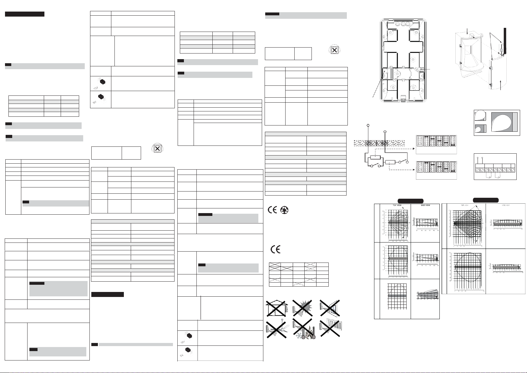
Figure 1.
Back cover - Knockouts
Back tamper
“Breakable” plate -
Not applicable in
this version
Figure 3.
Schematic of EOL Resistors
Tamper / Alarm EOL Jumpers
+12- ALARM TAMPER FAULT/AM LED
PANEL DEOL
ALARM
Figure 6.
RK815DTGL/RK825DTGL
Lenses and Microwave Range
Feet
RL115D (Wide Angle)
Meters
Feet
RL15 (Corridor)
Feet
2
0 0
10 2
4
20 6
RL115C (Curtain)
30 8
4 6
Meters
0 2
0 10 20 30
Feet
TAMPER
8
RK815DTGL
Feet
Meters
Feet
Feet
Meters
Feet
4
0
0
Meters
Feet 0
10 12
40
No
Resistor
0
Range
Adjustment Bolt
Thread
J1 - ALARM EOL JU MPERS
1K 2.2K 4.7 K 5.6K 6.8K
J2 - TAMPER EOL JUMPERS
No 1K 2.2K 4.7 K 5.6K 6.8K
Resistor
(Factory Settings)
Feet
RL125H (Wide Angle)
Meters
Feet
Feet
Meters
4
6
10
20
Feet
8
10
12
40
Figure 2.
Lens Replacement
Sleeve
Figure 4.
MW range adjustment
Figure 5.
Terminal Wiring
Short Pin
(Facing
upwards)
Cut
Corners
Lens
1
2 A
3
12VDC
+ 12 - ALARM TAMPER FAULT/AM LED
RK825DTGL
Meters
Feet
B
 Loading...