

Risco RK350DT User Manual
Beyond DT Wired
Outdoor Detector
Installation Instructions
Model: RK350DT

Description
The Beyond™ DT has been designed to provide enhanced 24-hour outdoor protection, with Active IR
Anti-mask capabilities. Integrated Dual Technology (DT) combines two K-band microwave channels
with two PIR sensors for better catch performance and pet immunity, minimizing false alarms. The
Beyond™ DT can also be installed on the RISCO Bus saving time and money.
Features include
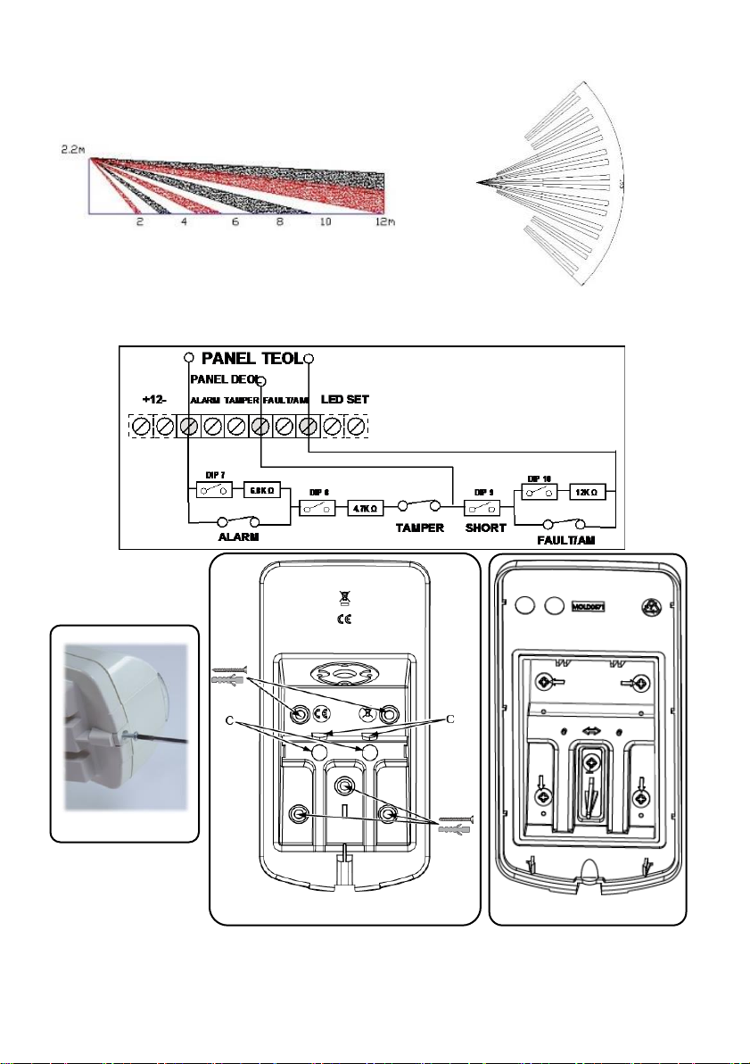
• PIR coverage: 12m, 90°
• Two channel K band - MW detection (Sway Recognition)
• Pet friendly (pet immunity)
• Two correlated PIR Sensors
• Light sensor for reducing false alarms due to sunlight
• Active IR Anti mask
• Mounting at 2.2m with optional swivel bracket
• Designed for outdoor installation, UV resistant, IP 54
• Cover and wall tampers
• Optional Swivel Bracket (Model: RA350S)
Installation
Step 1: Preliminary Considerations
Select the mounting location for best coverage of the area that is to be protected (see Coverage
Patterns). Pay attention to the following:
• Install the device at a height of 2.2m (7 ft 2 in). Any lower installation will reduce the detection
range accordingly.
• For pet immunity, the height of an animal (without weight limitation) is up to 50 cm (1ft 6 in)
when the device is installed at 2.2 m (7ft 2 in). Any lower installation will reduce the pet
immunity accordingly.
• Install the device in a location where the detector’s field of view is clear of any static obstacles.
• Mount the device so that walking traffic cuts across the beam pattern.
• Do not install the device close to any moving objects.
• Do not install more than one DT detector within a 1m radius.
Step 2: Mounting the Detector on Wall Bracket
1. Unscrew the fastening screw and remove the detector from the mounting bracket (see Figure 1).
2. Open the 5 knockout holes of the wall bracket, and use as a template for mounting (see Figure 2).
3. Insert external wiring through the cable channel on the back of the wall bracket (see Figure 2).
4. Secure the wall bracket to the wall (see Figure 3).
5. Connect the Terminal Block to the detector (see Figure 4).
6. Connect the terminal wiring (see Step 5a).
7. Set the DIP switch settings (see Step 5b).
8. Mount the detector to the wall bracket (see Figure 5).
2
9. Perform a walk test (see Step 7).
Mounting height [m]
Swivel Angle [°]
Distance [m]
1.8 0 10
5
7
10
5
2.2 (optimal)
0
12
5
8
10
6
2.5 0 N/A
5
10
10
7
2.7 0 N/A
5
10 10
7
10. Insert and fasten the screw to lock the detector (see Figure 5).
Step 3: PIR Coverage
NA = Avoid such installation
Step 4: Setting Detector Mode
Standalone Mode
1. DIP SW 6 is OFF
2. Terminal wiring as in Step 5a
RISCO BUS Mode
1. DIP SW 6 is ON
2. Wiring:
a) + - terminal − Detector 12 VDC, - GND
b) Connecting YEL / GRN – Detector BUS
c) Continue to step 6
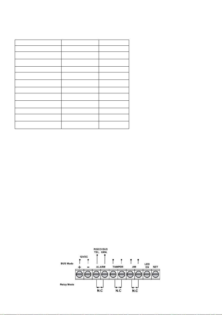
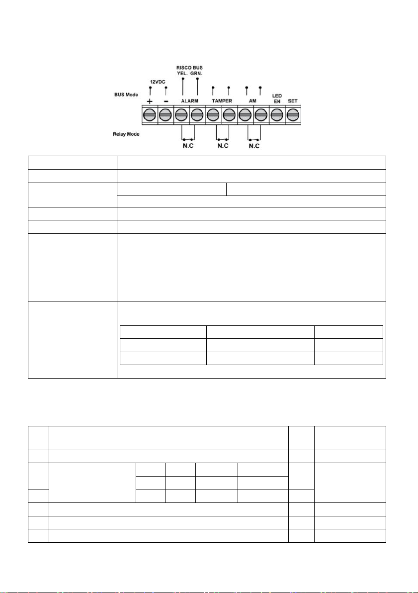
Step 5a: Connecting the Terminal Wiring (Standalone Mode)
Connect the terminal wiring according to the following:
3
Terminal
Description
+ -
+12 VDC, - GND
ALARM YEL GRN
N.C alarm relay
YEL / GRN (RISCO BUS)
NOTE: As defined by DIP SW 6
TAMPER +-
N.C tamper switch
AM +-
N.C anti mask alarm relay
LED ENABLE
Used to remotely control the LEDs when DIP1 is set to ON
Enable: input is +12V OR no terminal connection
Disable: Connect the input to 0V
This feature prevents an intruder from gaining knowledge of the
detector’s status and disables anti-mask detection.
SET / UNSET
This input enables controlling anti-masking operation in accordance to the
system status, Set (Arm) / Unset (Disarm).
System Status
Input Status
AM Relay
Set (Arm)
0V
Off
Unset (Disarm)
12V or no connection
On*
* DIP SW 4 is ON (Anti mask enabled)
NOTE: Make sure that jumper J5 is installed to bypass the Swivel Tamper.
DIP
SW
Description
Def.
Def. Status
1*
LEDs: ON: Enable / OFF: Disable
ON
LEDs ON
2*
Sensitivity (PIR)
Low
Mid.
Norm.
Max.
ON
Normal
OFF
OFF
ON
ON
3*
OFF
ON
OFF
ON
OFF
4*
Anti Masking: ON: Enable / OFF: Disable
ON
Enable
5*
High Sensitivity (Anti Mask): ON: High /OFF: Low
OFF
Low 6 Mode: ON: BUS / OFF: Relay (see Defining BUS ID)
OFF
Relay
Relay mode
DIP SW 7
DIP SW 8
DIP SW 9
DIP SW 10
Normal
OFF
OFF
OFF
OFF
DEOL
ON
ON
OFF
OFF
TEOL
ON
ON
ON
ON
MIN
MAX
Adjust microwave coverage area by using the trimmer on the PCB.
Step 5b: Setting DIP Switch Settings (Standalone Mode)
Set the DIP switch settings according to the table, below:
NOTES:
1. For DEOL DIP switches 7 and 8 should both be ON.
2. For TEOL DIP switch 7-10 should be ON.
4
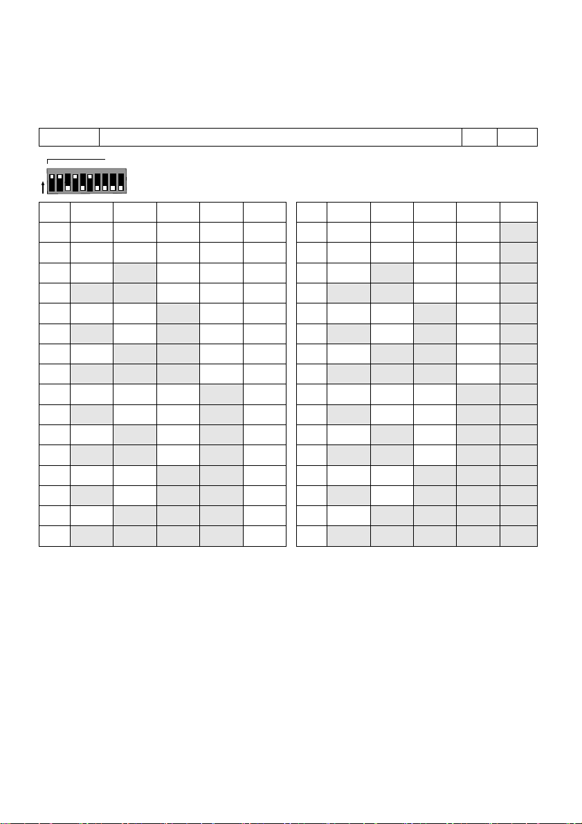
Step 6a: Defining the BUS ID (BUS Mode)
6
Mode: ON: BUS / OFF: Relay (see Defining BUS ID)
ON
BUS
ID
1 2 3 4 5 ID 1 2 3 4
5
01
OFF
OFF
OFF
OFF
OFF 17
OFF
OFF
OFF
OFF
ON
02
ON
OFF
OFF
OFF
OFF 18
ON
OFF
OFF
OFF
ON
03
OFF
ON
OFF
OFF
OFF 19
OFF
ON
OFF
OFF
ON
04
ON
ON
OFF
OFF
OFF 20
ON
ON
OFF
OFF
ON
05
OFF
OFF
ON
OFF
OFF 21
OFF
OFF
ON
OFF
ON
06
ON
OFF
ON
OFF
OFF 22
ON
OFF
ON
OFF
ON
07
OFF
ON
ON
OFF
OFF 23
OFF
ON
ON
OFF
ON
08
ON
ON
ON
OFF
OFF 24
ON
ON
ON
OFF
ON
09
OFF
OFF
OFF
ON
OFF 25
OFF
OFF
OFF
ON
ON
10
ON
OFF
OFF
ON
OFF 26
ON
OFF
OFF
ON
ON
11
OFF
ON
OFF
ON
OFF 27
OFF
ON
OFF
ON
ON
12
ON
ON
OFF
ON
OFF 28
ON
ON
OFF
ON
ON
13
OFF
OFF
ON
ON
OFF 29
OFF
OFF
ON
ON
ON
14
ON
OFF
ON
ON
OFF 30
ON
OFF
ON
ON
ON
15
OFF
ON
ON
ON
OFF 31
OFF
ON
ON
ON
ON
16
ON
ON
ON
ON
OFF 32
ON
ON
ON
ON
ON
1 2 3 4 5 6 8 97 10
BUS ADDRESS
O
N
Use DIP switches 1 to 5 to define the BUS ID of each detector. Define the BUS ID settings according to
the table below.
Set DIP switch setting 6 according to the following data:
* Default settings
NOTE: This step is only relevant for detectors that are connected to the RISCO BUS.
Step 6b: Defining System Settings (BUS Mode)
LightSYS / ProSYS Plus – Add the BUS detector
1. Select Installer menu: [7] Install > [1] BUS Device > [1] Automatic. The system automatically searches
for the detectors BUS ID and assigns a zone (according to the defined DIP switch settings).
2. Scroll to the defined zone with type ODT50 and click OK to confirm.
Configure the BUS detector parameters:
Select Installer menu: [2] Zones > [1] Parameters > [2] By Category > [7] Advanced [4] BUS Zone
Parameters (see LightSYS / ProSYS Plus Installation Manual).
NOTE: For LightSYS Version 5.20 and above.
5

Step 7: Performing a Walk Test
LED
State
Description
YELLOW
Blink ON
Indicates start of PIR detection analysis
Steady ON
Indicates PIR detection
Flashing
Indicates Active IR AM (Anti mask) detection
GREEN
Steady ON
Indicates MW detection
RED
Steady ON
Indicates ALARM
Flashing
Indicates malfunctioned communication with
the RISCO system (BUS Mode only)
All LEDs
Flashing (One after another)
Unit initialization on power up
Electrical
Current consumption:
30mA at 12 VDC (Stand by)
42mA at 12 VDC (MAX with LED ON)
Power output
16dBm
Voltage requirements
9 -16 VDC
Alarm contacts
24 VDC, 0.1A
AM contacts
24 VDC, 0.1A
Tamper contacts
24 VDC, 0.1A
Physical
Size (LxWxD):
170 x 90 x 90mm
Weight:
0.532 Kg
Environmental
RF Immunity:
According to EN50130-4
Operating Temperature:
-30C to 60C (90% humidity)
Storage Temperature:
-30C to 70C (90% humidity)
The detector cover should be closed during the walk test. Apply power and wait at least two minutes for
the detector to stabilize. Upon detection the detector transmits a signal and the LEDs light-up. Walk
through the entire protected area and observe the LEDs to confirm full coverage (see LED Status).
Manually initiate a walk test:
Select User Menu: Maintenance > Walk Test > Select Full Walk Test or Quick Walk Test. The detector
remains in walk test mode until any key on the panel is pressed.
LED Status
NOTE: DIP-SW 1 should be in ON position to enable LED indications.
Self-Test
Every hour the detector performs an internal self-test for both PIR and MW channels. A fault detected
in the self-test will be indicated by a momentary open anti-mask relay (in relay mode) or by a
corresponding message in the panel (in BUS mode).
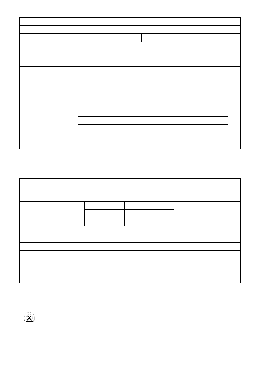
Specifications
6
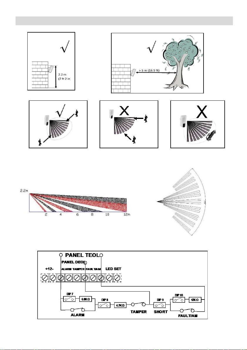
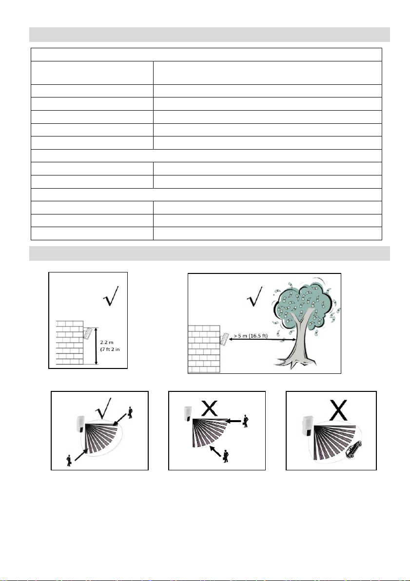
Preliminary Considerations
Side View
Top View
NOTE: Avoid installation facing moving cars / road at a distance of up to 30m.
PIR Coverage Pattern: 12m, 90°
Termination Resistance
7
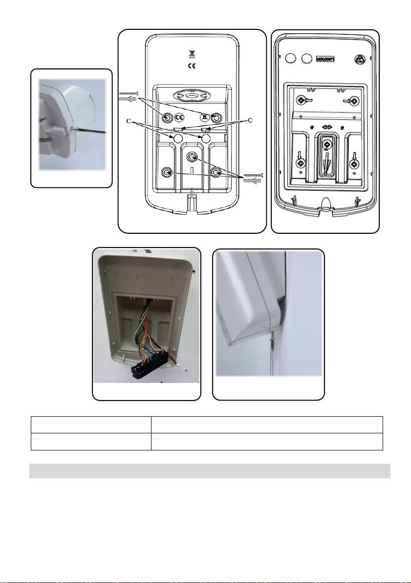
Figure 1
Figure 2
Figure 3
Figure 4
Figure 5
RK350DT0000A
Beyond DT, K Band Detector
RA350S00000A
180 Swivel for Beyond DT
Ordering Information
RED Compliance Statement
Hereby, RISCO Group declares that this equipment is in compliance with the essential requirements
and other relevant provisions of Directive 2014/53/EU. For the CE Declaration of Conformity please
refer to our website: www.riscogroup.com
8

Description
Le Beyond™ DT a été conçu pour assurer une protection extérieure fiable 24 heures sur 24, avec une
fonction d’anti-masque à IR actif. La double technologie (DT) intégrée associe deux canaux
hyperfréquences bande K à deux capteurs IRP de façon à optimiser les performances de détection et
l'immunité aux animaux, pour ainsi minimiser les fausses alarmes. Le Beyond™ DT peut aussi être
installé sur le Bus RISCO pour un gain de temps et d'argent.
Principales fonctionnalités
• Couverture IRP : 12 m, 90°
• 2 canaux de détection hyperfréquence bande K (reconnaissance des mouvements de balancier)
• Immunité aux animaux
• Deux capteurs IRP en corrélation
• Capteur optique pour réduire les fausses alarmes provoquées par la lumière du soleil
• Anti-masque à IR actif
• Installation à 2,2 m avec un support de fixation en option
• Conçu pour une installation en extérieur, résistant aux UV, indice IP 54
• Autoprotection à l'ouverture et à l'arrachement
• Support pivotant en option (modèle : RA350S)
Installation
Étape 1 : Considérations préliminaires
Sélectionnez l'emplacement de montage le mieux adapté pour couvrir la zone à protéger (reportezvous à la section Couverture IRP). Respectez les consignes suivantes :
• Installez l'appareil à une hauteur de 2,2 mètres. Toute installation à une hauteur inférieure risque
de réduire la portée de détection.
• Pour l'immunité aux animaux, l'animal doit mesurer 50 cm maximum (sans limitation de poids)
lorsque l'appareil est installé à 2,2 m. Toute installation à une hauteur inférieure réduira
l’immunité aux animaux en conséquence.
• Installez l'appareil dans un lieu où aucun obstacle statique n'obstrue le champ de vision du
détecteur.
• Installez l'appareil de façon à ce que les personnes qui marchent dans la zone surveillée coupent
les faisceaux de détection.
• N'installez pas l'appareil à proximité d'objets en mouvement.
• N'installez pas plusieurs détecteurs DT dans un rayon de 1 mètre.
Étape 2 : Installation du détecteur sur le support mural
1. Desserrez la vis de fixation et retirez le détecteur du support de montage (reportez-vous à la
Figure 1).
9

2. Ouvrez les 5 trous marqués du support mural et utilisez-les comme gabarits pour l'installation
Hauteur d'installation [m]
Angle de pivotement [°]
Distance [m]
1,8 0 10
5
7
10
5
2,2 (optimale)
0
12
5
8 10
6
2,5 0 N/A
5
10
10
7
2,7 0 N/A
5
10 10
7
(reportez-vous à la Figure 2).
3. Insérez les câbles externes dans la voie de câbles à l'arrière du support mural (reportez-vous à la
Figure 2).
4. Fixez le support de montage au mur (reportez-vous à la Figure 3).
5. Récupérez le bornier débrochable pour le câbler (reportez-vous à la Figure 4).
6. Câblez le bornier débrochable (reportez-vous à l'Étape 5a).
7. Raccordez le bornier débrochable, puis configurez les DIP Switchs (reportez-vous à l'Étape 5b).
8. Montez le détecteur sur le support mural (reportez-vous à la Figure 5).
9. Effectuez un test de marche (reportez-vous à l'Étape 7).
10. Insérez la vis et serrez-la pour fixer le détecteur (reportez-vous à la Figure 5).
Étape 3 : Couverture IRP
N/A = Évitez ce type d'installation
Étape 4 : Sélection du mode du détecteur
Mode Autonome
1. Le DIP Switch 6 est en position OFF
2. Câblage du bornier conformément à l'Étape 5a
Mode Bus RISCO
1. Le DIP Switch 6 est en position ON
2. Câblage :
a) Borne + - − Alimentation du détecteur 12 V CC, - 0 V
b) Câblages des bornes YEL/GRN – Bus du détecteur
c) Passez à l'étape 6
10
Étape 5a : Câblage du bornier (mode Autonome)
Borne
Description
+ -
+12 V CC, - 0 V
ALARM YEL GRN
Relais d’alarme N.F
YEL/GRN (Bus RISCO)
REMARQUE : selon la configuration du DIP Switch 6
TAMPER + -
Relais d'autoprotection N.F
AM + -
Relais d’alarme anti-masque N.F
LED ENABLE
Borne utilisée pour contrôler à distance les LEDs lorsque le DIP Switch 1
est réglé sur ON
Activé : l'entrée est de +12 V ou aucune connexion à la borne
Désactivé : raccordez cette entrée sur 0 V
Cette fonction empêche un intrus de connaître l'état du détecteur et
désactive la détection anti-masque.
SET/UNSET
Cette entrée permet de contrôler l'opération d'anti-masquage en fonction de
l'état du système : Set (Armé) / Unset (Désarmé).
État du système
État de l'entrée
Relais AM
Set (Armé)
0 V
Désactivé
Unset (Désarmé)
12 V ou pas de connexion
Activé*
* Le DIP Switch 4 est réglé sur ON (anti-masque activé)
DIP
SW
Description
Déf.
État déf.
1*
LEDs : ON : activées / OFF : désactivées
ON
LEDs activées
2*
Sensibilité (IRP)
Faible
Moyen
Normal
Max.
ON
Normal
OFF
OFF
ON
ON
3*
OFF
ON
OFF
ON
OFF
4*
Anti-masque : ON : activé / OFF : désactivé
ON
Activé
5*
Haute sensibilité (AM) : ON : élevée / OFF : faible
OFF
Faible
6
Mode : ON : Bus / OFF : Relais (voir Définition de l'ID Bus)
OFF
Relais
Câblez le bornier en procédant comme suit :
REMARQUE : vérifiez que le cavalier J5 est installé pour ignorer l'autoprotection du support.
Étape 5b : Configuration des DIP Switch (mode Autonome)
Configurez les DIP Swicth en vous reportant au tableau ci-dessous :
11

Mode relais
DIP Switch 7
DIP Switch 8
DIP Switch 9
DIP Switch 10
Normal
OFF
OFF
OFF
OFF
DEOL
ON
ON
OFF
OFF
TEOL
ON
ON
ON
ON
REMARQUES :
MIN
MAX
Réglez la zone de couverture des canaux hyperfréquences à l'aide du potentiomètre du
PCB.
6
Mode : ON : Bus / OFF : Relais (voir Définition de l'ID Bus)
ON
BUS
ID
1 2 3 4 5 ID 1 2 3 4
5
01
OFF
OFF
OFF
OFF
OFF 17
OFF
OFF
OFF
OFF
ON
02
ON
OFF
OFF
OFF
OFF 18
ON
OFF
OFF
OFF
ON
03
OFF
ON
OFF
OFF
OFF 19
OFF
ON
OFF
OFF
ON
04
ON
ON
OFF
OFF
OFF 20
ON
ON
OFF
OFF
ON
05
OFF
OFF
ON
OFF
OFF 21
OFF
OFF
ON
OFF
ON
06
ON
OFF
ON
OFF
OFF 22
ON
OFF
ON
OFF
ON
07
OFF
ON
ON
OFF
OFF 23
OFF
ON
ON
OFF
ON
08
ON
ON
ON
OFF
OFF 24
ON
ON
ON
OFF
ON
09
OFF
OFF
OFF
ON
OFF 25
OFF
OFF
OFF
ON
ON
10
ON
OFF
OFF
ON
OFF 26
ON
OFF
OFF
ON
ON
11
OFF
ON
OFF
ON
OFF 27
OFF
ON
OFF
ON
ON
12
ON
ON
OFF
ON
OFF 28
ON
ON
OFF
ON
ON
13
OFF
OFF
ON
ON
OFF 29
OFF
OFF
ON
ON
ON
14
ON
OFF
ON
ON
OFF 30
ON
OFF
ON
ON
ON
15
OFF
ON
ON
ON
OFF 31
OFF
ON
ON
ON
ON
16
ON
ON
ON
ON
OFF 32
ON
ON
ON
ON
ON
1 2 3 4 5 6 8 97 10
BUS ADDRESS
O
N
1. Pour un câblage DEOL, les DIP Switch 7 et 8 doivent être sur ON.
2. Pour un câblage TEOL, les DIP Switch 7 à 10 doivent être sur ON.
Étape 6a : Définition de l'ID Bus (mode BUS)
Utilisez les DIP Switch 1 à 5 pour définir l'ID Bus de chaque détecteur. Définissez les paramètres d'ID
Bus en vous reportant au tableau ci-dessous.
Configurez le commutateur DIP 6 en fonction des données suivantes :
* Paramètres par défaut
REMARQUE : cette étape s'applique uniquement aux détecteurs connectés au bus
RISCO.
12

Étape 6b : Configuration des paramètres système (mode Bus)
LED
État
Description
JAUNE
1 seul clignotement
Indique le début de l'analyse de détection IRP
Fixe
Indique une détection IRP
Clignotement continu
Indique une détection AM (anti-masque) à IR actif
VERT
Fixe
Indique une détection hyperfréquence
ROUGE
Fixe
Indique une alarme
Clignotement continu
Indique une erreur de communication avec le
système RISCO (mode Bus uniquement)
Toutes les LEDs
Clignotement continu
(l’une après l’autre)
Initialisation de l'unité après la mise sous tension
LightSYS / ProSYS Plus – Ajout du détecteur Bus
1. Allez dans le menu Installateur : Programmation > [7] Install > [1] Access. BUS > [1] Automatique.
Le système cherche automatiquement l’ID Bus des détecteurs et les assigne à une zone (selon l’ID
défini par la configuration des DIP Switch).
2. Vérifiez que la zone est bien reconnue en type ODT50 et cliquez sur OK pour confirmer.
Configuration des paramètres du détecteur Bus :
Allez dans le menu Installateur : Programmation > [2] Zones > [1] Paramètres > [2] Par catégorie > [7]
Avancée > [4] Param. Z. Bus (reportez-vous au guide d'installation de la LightSYS/ProSYS Plus).
REMARQUE : pour LightSYS v5.20 et les versions ultérieures.
Étape 7 : Test de marche
Le couvercle du détecteur doit être fermé lors du test de marche. Mettez le détecteur sous tension et
attendez au moins deux minutes qu'il se stabilise. Pendant la détection, le détecteur transmet un
signal et la LED s'allume. Parcourez la zone protégée et observez les LEDs pour vérifier que la zone
est entièrement couverte (reportez-vous à la rubrique État des LEDs).
Lancement manuel du Test de marche :
Allez dans le menu Utilisateur ou Installateur : Maintenance > Test de marche > Test complet ou Test
rapide. Le détecteur reste en mode Test de marche tant que vous n'appuyez sur aucune touche.
État des LEDs
REMARQUE : Le DIP Switch 1 doit être en position ON pour activer les indications
LEDs.
Test automatique
Toutes les heures, le détecteur effectue un test automatique interne pour les canaux IRP et
hyperfréquences. Toute erreur détectée au cours d'un test automatique est indiquée par un relais antimasque momentanément ouvert (en mode Relais) ou par un message correspondant sur la centrale
(en mode Bus).
13
Spécifications
Électriques
Consommation électrique :
30mA à 12 VCC (Repos)
42mA à 12 VCC (MAX avec LEDs activées)
Puissance disponible
16dBm
Tension requise :
9 -16 VCC
Contacts d'alarme :
24 VCC, 0.1A
Contacts anti-masque :
24 VCC, 0.1A
Contacts autoprotection :
24 VCC, 0.1A
Physiques
Dimensions (LxlxP) :
170 x 90 x 90mm
Poids :
0.532 Kg
Environnementales
Immunité RF :
Selon la norme EN50130-4
Température de fonctionnement :
-30C à 60C (90% d’humidité)
Température de stockage :
-30C à 70C (90% d’humidité)
Considérations préliminaires
REMARQUE : Evitez d'installer le détecteur face à une route / des véhicules en
mouvement à moins de 30 m maximum.
14
Couverture IRP : 12 m, 90°
Figure 1
Figure 2
Figure 3
Vue latérale
Vue de dessus
Résistances de fin de ligne
15
 Loading...