

Risco RK315DT Users Manual
Dual Technology Outdoor Detector
RReellaayy M
Mooddee IInnssttaallllaattiioonn IInnssttrruuccttiioonnss
WatchOUT DT Relay Mode Installation
WatchOUT Dual Technology Outdoor Detector: Relay Mode Installation
Rokonet’s Dual Technology Outdoor detector, WatchOUT, is a unique detector with signal processing based on two Passive Infrared (PIR)
channels and two Microwave (MW) channels. The detector can operate as a regular relay detector connected to any control panel, or as a BUS
accessory when connected to Rokonet’s ProSYS control panel via the RS485 BUS, thus having unique remote control and diagnostic
capabilities.
The following instructions describe the installation of the WatchOUT in Relay mode. For detailed information regarding BUS mode installation
refer to BUS mode installation instructions (5IN315DTB)
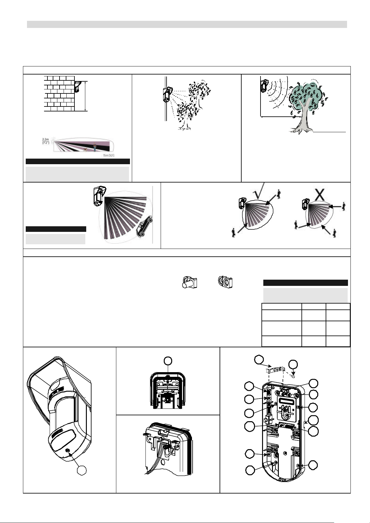
Mounting Considerations
1m - 2.7m
(3'3" - 8'9")
Optional Height: 1m – 2.7m (3'3"-8'9 ")
Typical Height: 2.2m (7'2")
Default Lens: Wide angle 15m (50') 90°
Note:
For low installations, below 1.7m (5'6") in which pet
immunity is required, use the supplied RL300F lens
(Low wall or fence installations)
For installations with
extensive vehicle traffic or
targets beyond the
required detection range it
is recommended to adjust
the MW sensitivity and/or
to tilt the detector down.
Note:
Tilting the detector down may
reduce the pet immunity
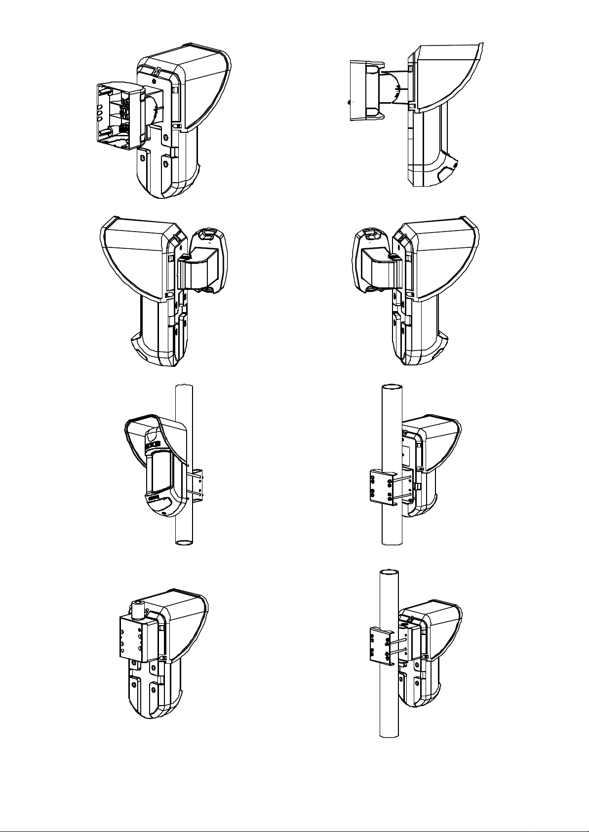
Wall Mount Installation
1. Open WatchOUT front cover. (Unlock C1, figure 1).
2. Release internal base (unlock I1, figure 2).
3. Select mounting installation as follows:
Flat Mounting:
a. Open knockouts on external base (figure 3)
Ø B1-B4: Wall mounting knockouts.
Ø T1 : Back tamper knockout
Ø W2 / W3: Wire entry knockouts.
45° angle Mounting (Left side mounting)
a. Open knockouts on external base (figure 3)
Ø L1, L2 : Left mounting knockouts
Ø T3 : Left tamper knockout
Ø W2 / W3: Wire entry knockouts
Figure 1:
If possible avoid pointing the detector to
moving objects (swaying trees, bushes etc)
Figure 2:
For optimum detection,
select a location that is
likely to intercept an
intruder moving across
the coverage pattern at a
45° trajectory.
b. Remove tamper sp ring
c. Replace tamper bracket 1 with supplied
flat tamper bracket 2.
1
d. Insert tamper lever B onto T5 and T3
and secure screw A (figure 3)
4. Insert external wires through external
base W2, W3. (figure 3)
5. Secure external base to the wall.
6. Insert external wires and tamper wires
through internal base. (figure 4)
7. Secure internal base to external base
(lock I1, figure 2).
I1
2
Figure 3:
5m (16')
Keep distance of
minimum 5m (16')
from moving objects
Out of
Detection Range
Ensure any objects do not obstruct the field of
view for both technologies. Pay attention to
growing trees or bushes, plants with big
moving leaves etc.
8. Close the front cover (Lock C1,
figure 1) after wiring and setting
Dip switches.
9. Walk test the detector
Note:
For 45° right side installation use the
equivalent units on the external base as
follows:
Left Right
Tamper
Lever
Mounting
Knockouts
Tamper
spring
knockouts
Tamper
screw anchor
B
L1, L2 R1, R2
T1,T3 T2,T4
T5 T6
A
C1
Figure 4:
WatchOUT DT Relay Mode Installation
T3
L1
B1
W3
L2
B4
T1
T5
B2
W9
W2
B3
 Loading...