


D T
A M
G r a d e
3
H i g h
C e i l i n g
M o u n t
D e t e c t o r
I n s t a l l a t i o n
G u i d e
M o d e l : R K 2 0 0 D T G 3
DT AM Grade 3
Model: RK200DTG3
High Ceiling Mount Detector Installation Guide
General Description
The Industrial LuNAR DT AM Grade 3 (RK200DTG3) is a dual technology ceiling detector with a mounting height of
up to 8.6m (28ft) that incorporates RISCO Group’s Anti-Cloak™ Technology (ACT™). The detector has an Intelligent
Digital Signal Processing method that automatically adjusts the alarm threshold and pulse count verification
according to actual intruder crossing speed and environmental factors, providing superior detection and false
alarm immunity.
The Ind. LuNAR RK200DTG3 can operate as a regular relay detector connected to any control panel, or as an
addressable BUS detector when connected to RISCO Group’s ProSYS control panel via the RS485 BUS.

Ind. LuNAR RK200DTG3 Features
♦
PD6662, EN50131-1, EN50131-2-4 Grade 3
♦
Addressable Dual Technology detector with Anti-Cloak™ Technology
♦
Up to 8.6 m (28ft) mounting height
♦
3600 by 18m (60ft) diameter coverage pattern
♦
3 independent PIR channels for customized coverage
♦
Intelligent Digital Signal Processing – alarm verification and decision thresholds adjusted according to
actual intruder crossing speed
♦
Built-in Triple EOL resistors, jumper selectable
♦
Active IR for Anti-Masking meeting EN50131 requirements
♦
Ceiling and cover tampers
♦
"Green Line" setting – for disabling the MW when the premises are occupied
♦
Opto–relays for low current consumption and long life
♦
Remote and Local Self Test
♦
Remote SET input
♦
Remote RC control input
♦
PIR coverage optimization by sliding the lenses
♦
Microwave Range Adjustment manually (analog trimmer) and remotely (digital setting)
♦
Trouble Indication (by LEDs or via communication)
♦
3 Triple color LEDs for easy walk testing
♦
Advanced Remote control and diagnostics
♦
Reduced Power Consumption when connected to RISCO Group’s ProSYS
2 Ind. LuNAR RK200DTG3 Installation Guide

Remote Control and Diagnostic Features
*
♦
Remote microwave adjustment enables one-man walk test.
♦
Diagnostic tools include detector input voltage reading and status of each PIR channel and MW
channel (signal voltage and noise levels), AM channel (signal voltage), SW version verification.
♦
Remote display and control of detector settings: MW adjustment, ACT on/off, LEDs on/off.
♦
Remote trouble indication (Pass/Fail) for the PIR, MW and power supply input
♦
Control of MW bypass (during MW trouble) and MW disable during Disarm ("Green Line") when
connected to ProSYS.
*Via the optional Bi-Directional Infrared Remote Control, or the ProSYS Upload/Download Software and
Keypad.
Detection Method
The Ind. LuNAR RK200DTG3 detection is based on:
♦ PIR (Passive Infra-Red) - which responds to changes in the IR radiation caused when an intruder crosses
the protected area.
♦ MW (Microwave) - which transmits signals and analyzes the frequency changes of the reflected echo
from an intruder using Doppler Effect.
ALARM is initiated only when both technologies trigger simultaneously (except for certain situations in the ACT
mode-see page 4 – “How ACT™ Works”), thus greatly reducing the possibility of false alarms.
How ACT™ Works
Anti-Cloak™ Technology (ACT™) provides the benefits of DT (Dual Technology) while avoiding its
drawbacks. This patent pending innovation has created a new standard for detectors. Dual Technology, a
combination of PIR +MW, was an important development for the security industry...but, it has 2 major
weaknesses:
IR emission blocking cloaks employed by intruders enable avoidance of detection.
PIR sensitivity is reduced when the protected area’s ambient temperature approaches body temperature.
Responding to requests from its customer base to solve these pressing problems, RISCO Group developed
ACT™ -a revolutionary anti-cloak solution.
Ind. LuNAR RK200DTG3 Installation Guide 3

ACT™ prevents the alarm system from being bypassed, by neutralizing attempts to camouflage IR radiation.
Using unique pattern recognition algorithms, ACT™ distinguishes between the weak IR signal of a moving
intruder and the background noise and thermal interferences that may cause false alarms.
Once the presence of an intruder is recognized, ACT™ switches the system automatically from dual channel
PIR/MW mode to single channel MW mode for a predetermined period of time, in order to trigger an alarm
utilizing the MW channel, and then returns to dual channel mode.
In the second case, when the ambient temperature approaches body temperature, the ACT™ switches to
microwave-only detection.
Offering significantly higher detection capabilities as well as immunity from false alarms, ACT™ thwarts even
the most sophisticated burglars.
Ind. LuNAR RK200DTG3 Configuration Options
The Ind. LuNAR RK200DTG3 can be configured and/or diagnosed remotely via one of the options:
4 Ind. LuNAR RK200DTG3 Installation Guide
Manual
configuration
Remote
Control
Device
ProSYS Bus
Control
ACT Mode
LEDs
MW Sensitivity
(by trimmer)
Diagnostics
-
Status/Trouble/Info Reports
-
AM Diagnostics
-
-
MW Bypass
-
-
MW Disable on Disarm ("Green
Line")
-
-
LED Display
The three Tri color LEDs in the Ind. LuNAR RK200DTG3, operate as herein described:
Ind. LuNAR RK200DTG3 Installation Guide 5

LED
STATE
MEANING
Red
Steady
Detector alarm (simultaneous PIR and MW
detection)
Flashing with low frequency
Indicates malfunctioned communication with
ProSYS
Flashing with high frequency
AM detection
Green
Steady
Microwave detection
Flashing
Trouble in the MW channel
Orange
Steady
PIR detection
Flashing
Trouble in the PIR channel
All LEDs
Flashing with change of color
Upon power up
♦
Before installation, study the space to be protected carefully in order to choose the exact location of
the unit for the best possible coverage.
♦
Never install the Ind. LuNAR RK200DTG3 in an environment that causes an alarm condition in one
technology.
♦
Avoid installations where rotating machines (e.g. fans) are normally in operation within the coverage
pattern. Point the unit away from glass exposed to the outdoors and objects that may change
temperature rapidly.
♦
Do not mount the detector in direct sunlight or near any heat sources. Detection sectors should be
pointed either towards a wall, floor but not towards windows or curtains. The installation surface
should be solid, smooth and vibration free
♦
Eliminate interference from nearby outside sources.
INSTALLATION
Preliminary steps:
6 Ind. LuNAR RK200DTG3 Installation Guide

♦
For optimum detection, select a location likely to intercept an intruder moving across the coverage
pattern.
♦
Recommended mounting heights that allow 18m (60ft) detection, are from 3.7m to 8.6m.
♦
The detector must be mounted on the ceiling, preferably in the center of the room.
Typical Ind. LuNAR RK200DTG3 detection coverage and installation height, are illustrated below:
Ind. LuNAR RK200DTG3 Installation Guide 7
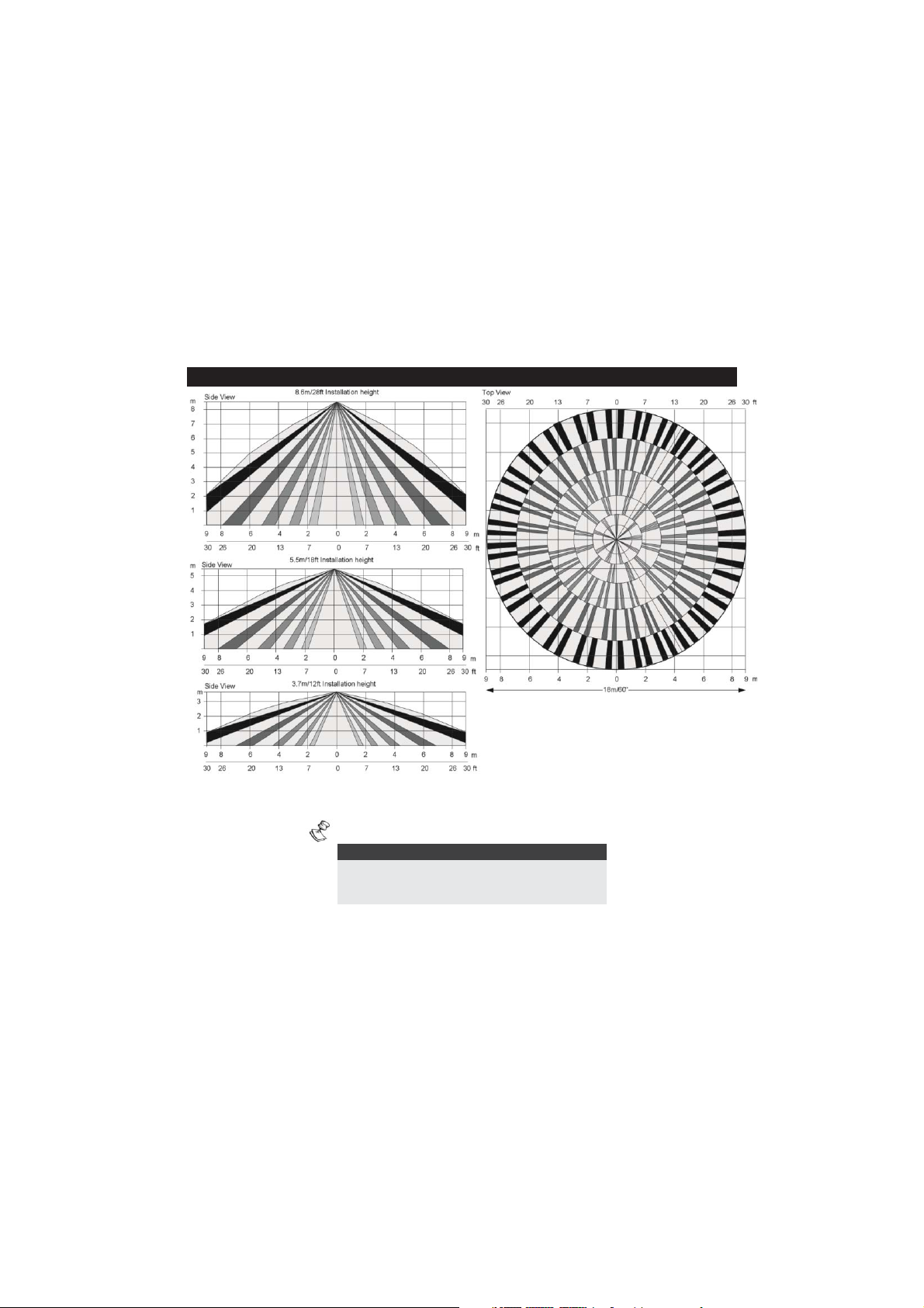
NOTE:
When installing the Ind. LuNAR RK200DTG3 detector in a
room occupied with high volume interfering elements, MW
detection may be affected.
8 Ind. LuNAR RK200DTG3 Installation Guide

Ind. LuNAR RK200DTG3 Installation Guide 9

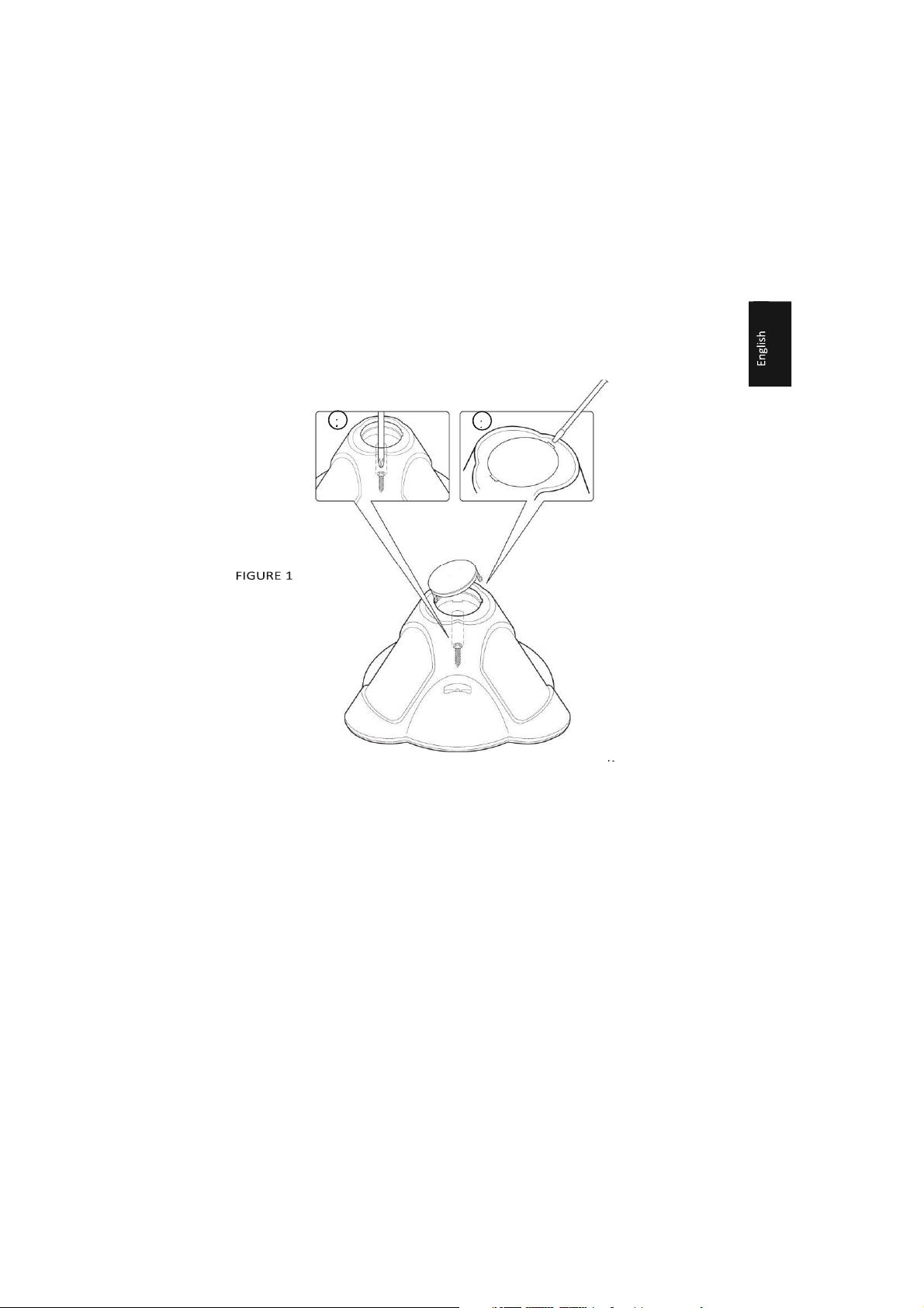
Installation Process:
To open the detector (Figure 1), remove the cover by inserting a screwdriver (1) in the recess between the
detector’s protection cap and the cover. The cover will remain attached to the base of the detector.
Using a Philips screwdriver, release the upper cover screw (2) and gently pull upward the detector’s upper
cover.
10 Ind. LuNAR RK200DTG3 Installation Guide
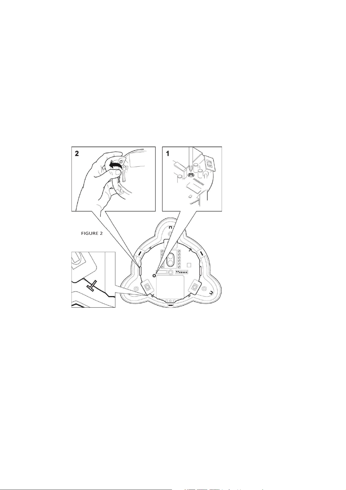
Release the PCB holding screw (Figure 2) located on the right hand side of the PCB (1), pull gently the two
release clips (2) outward and remove the PCB.
Ind. LuNAR RK200DTG3 Installation Guide 11
using a screwdriver.
Do not touch the PIR
sensors!
Do not remove
the white filters from
their
position! They are
essential for
correct operation
of the detector.
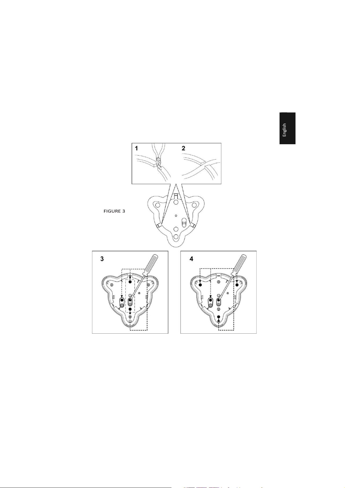
If required, open (Figure
3) the wiring channels
knockout using a cutter
(1, 2) and knockout holes
in the rear cover (3, 4)
12 Ind. LuNAR RK200DTG3 Installation Guide
Ind. LuNAR RK200DTG3 Installation Guide 13

Insert the cable via the cable opening (Figure 4) and connect the desired wires as described in “Step 4-
Wiring”.
14 Ind. LuNAR RK200DTG3 Installation Guide
Return the PCB to its previous location and verify that it is well secured by the holding clips and the screw.
Ind. LuNAR RK200DTG3 Installation Guide 15
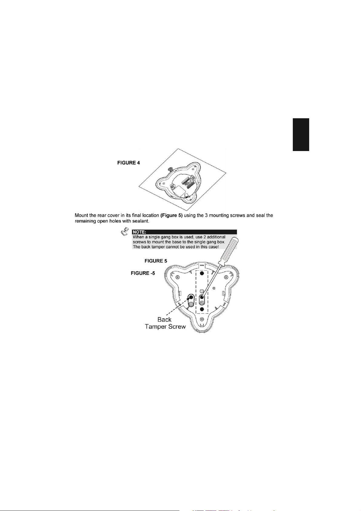
NOTE:
For a ceiling tamper, affix the back tamper screw as
shown in Figure 5.
Perform lens adjustment and DIP switch settings as described in “Lens Adjustment” on page 12 and on page
15.
Mount the top cover on the detector’s base.
Tighten the top cover’s central screw.
Replace the detector’s protection cap.
Lens Adjustment:
The Ind. LuNAR RK200DTG3 has three - Fresnel lenses attached to the cover, located in sensor protective
sleeves. Adjust the position of the lenses based on the ceiling mounting height as follows:
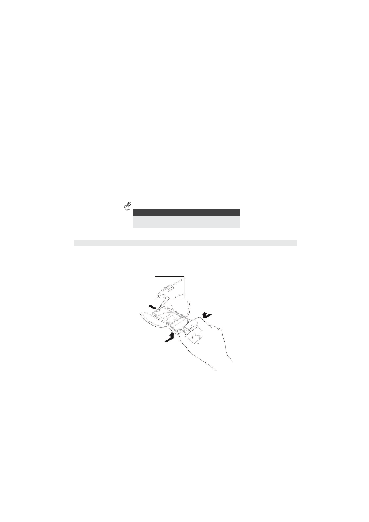
Press the 2 clips attaching the sleeve (Figure 6) to the detector’s cover, and gently pull out the sleeve.
16 Ind. LuNAR RK200DTG3 Installation Guide
FIGURE 6
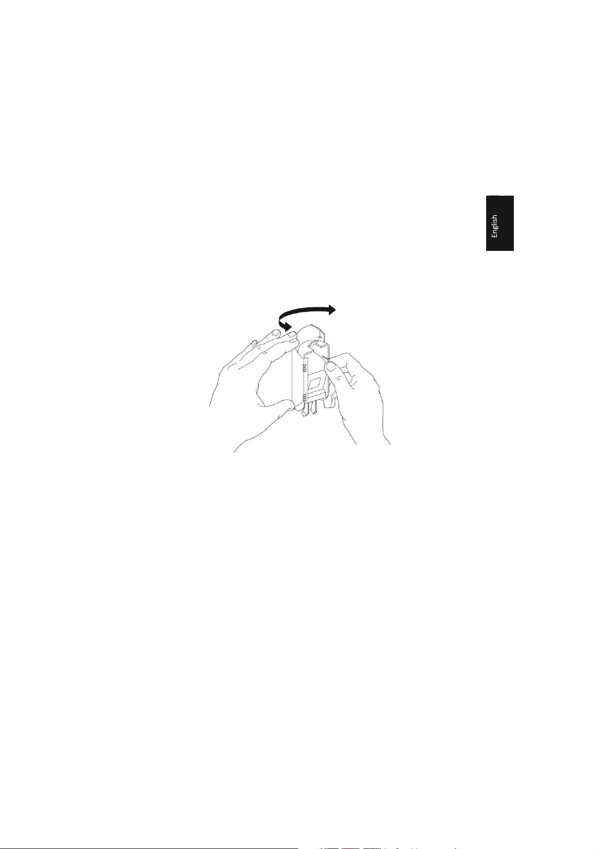
Remove the lens from the sleeve (Figure 7) by gently lifting it from the holding pins that secure it to the sides
of the sleeve.
FIGURE 7
Place the two pins, which are located on both sides of the sleeve into the matching slots on the lens. Use the
following table to select the desired lens position.
Ind. LuNAR RK200DTG3 Installation Guide 17
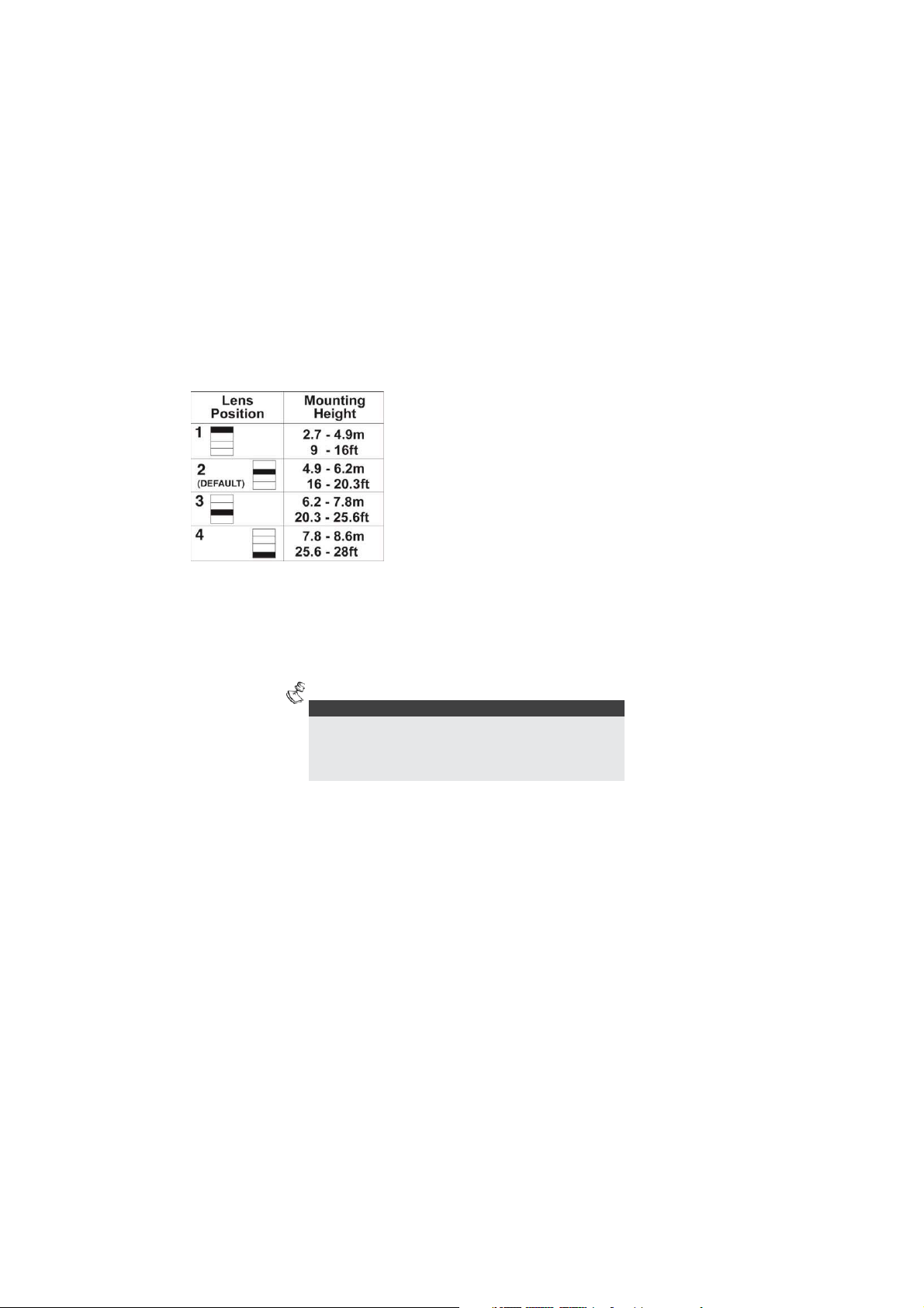
NOTES:
Below 3.7m mounting height, the coverage diameter starts
decreasing, and at 2.7m height coverage diameter is 15m (50ft). For
customized coverage, it is possible to set the position of each lens to a
different height, according to the installation conditions.
Return the protective sleeve back into place on the detector front cover.
Repeat steps 1 to 5 for the remaining 2 lenses.
18 Ind. LuNAR RK200DTG3 Installation Guide
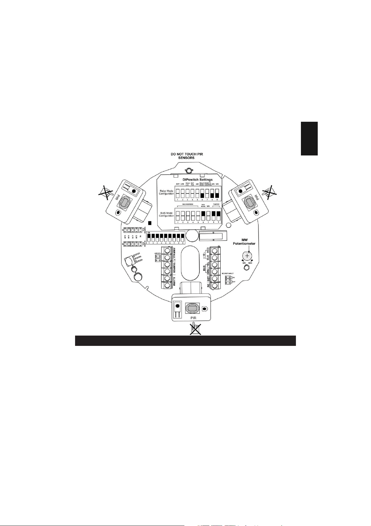
Selectors and Jumpers
Ind. LuNAR RK200DTG3 Installation Guide 19
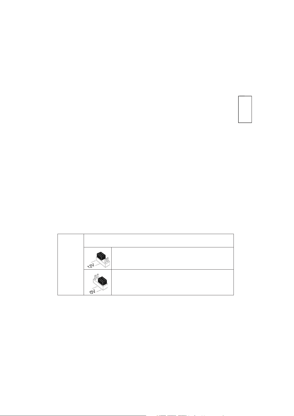
RC/SET INPUT
Used to determine the polarity of the external inputs.
0V: The GND has to be connected in order to activate the function.
12V: 12v has to be connected in order activate the function.
GND or N.C. has no influence on the RC/SET status. (see Relay
mode DIP switches configuration)
20 Ind. LuNAR RK200DTG3 Installation Guide
12v or N.C. has no influence on the RC/SET status. (see Relay
mode DIP switches configuration)

EOL RESISTORS
JUMPERS
The jumpers are used when connecting the detector to
a DEOL or TEOL Zone. The jumpers allow the selection
of TAMPER, ALARM E.O.L resistors (1K, 2.2K, 4.7K, 5.6K
or 6.8K), according to the control panel settings. An
additional double jumper allows the connection of 12K
FAULT/AM E.O.L resistor (see EOL Resistors Schematic).
Follow the terminal block connection diagram when
connecting the detector to a Double/Triple
End Of Line (DEOL/TEOL) Zone
Ind. LuNAR RK200DTG3 Installation Guide 21

1 2 3 4 5 6 7 8 9
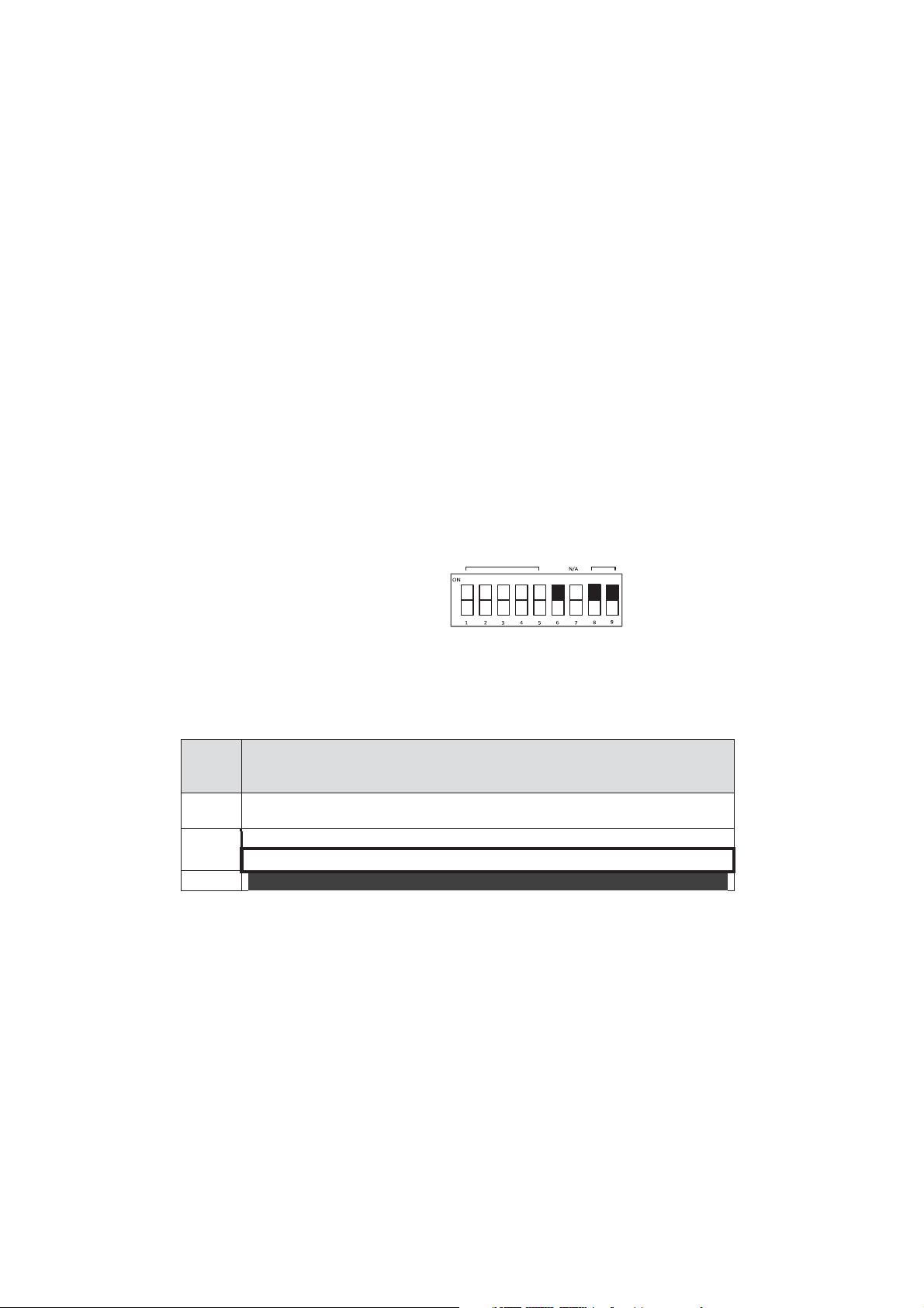
DIP Switch Settings
The Ind. LuNAR RK200DTG3 has a 9 position DIP switch that changes functionality for use in Relay mode or in
BUS operation mode. Set the DIP switch according to the tables below:
Factory Default Settings:
ON
22 Ind. LuNAR RK200DTG3 Installation Guide

Relay Mode Configuration (DIP
switch 6=OFF)
:
Number
Green Self RELAY REMOTE
ACT LED AM N/A
N/A Line Test
MODE CONTROL
ON
1 2 3 4 5 6 7 8 9
DIP switch Description
1 Used to determine the operation of the ACT
DIP switch ON: ACT is enabled
DIP switch OFF: ACT is disabled (default factory)
2 Used to determine the operation of the detector’s LEDs Dip switch ON: LEDs are
enabled (default factory)
DIP switch OFF: LEDs are disabled
3 Used to determine the operation of the "Green Line" (See Note below)
DIP switch ON: "Green Line" is enabled
DIP switch OFF: "Green Line" is disabled (default factory)
4 Used to determine the type of Self Test (See Note below) DIP switch ON: Local
Self Test:
In case the local self test fails, the FAULT/AM Relay is activated for a period of 2.5 secs. DIP
switch OFF: Remote Self Test (default factory):
In case the remote self test passes, the Alarm Relays are activated for a period of 5 secs.
In case the test fails, FAULT/AM Relay is activated for a period of 2.5 seconds.
5 Used to determine whether Active IR Anti-Masking is active. (See Note below)
DIP switch ON: Enable
DIP switch OFF: Disable (default factory)
IMPORTANT:
If the AM is enabled via DIP Switch 5, the cover must be fitted within 1 minute from applying the power.
If the detector is already powered up and DIP Switch 5 is turned on, the unit must be down powered to
reset the AM calibration.
6 Used to determine the detector’s connection mode DIP switch OFF: Relay mode
Used to determine if the Remote Control communication is enabled or disabled.
Ind. LuNAR RK200DTG3 Installation Guide 23
DIP switch
Number
Description
Used to set the detector ID number. (See Table 1)
Set the ID number in the same way as for any other ProSYS accessory.
Used to determine the detector’s connection mode.
DIP switch ON: ProSYS connection – BUS configuration
NOTE:
DIP switch ON: RC communication is always enabled.
DIP switch OFF: RC communication depends on the voltage applied to the terminal block 7 “RC”
(default factory)
8-9 DIP switches OFF
When an activation signal is applied to the RC input of the terminal block, RC is enabled.
IMPORTANT:
Turn dipswitch 7 “OFF” after installation and when leaving the site for security reasons. This will prevent
unauthorized use of a remote control unit that may be used to disable the detector.
NOTE:
See Set Terminal Blocks for activation details.
BUS Mode Configuration (DIP
MODE switch 6=ON):
1-5
6
24 Ind. LuNAR RK200DTG3 Installation Guide
BUS ADDRESS TAMPER
BUS
Upon power up or normal operation, the Ind. LuNAR RK200DTG3 waits 10 seconds for ProSYS
communication. Communication problem may occur due to bad wiring, wrong address, or ProSYS not
configured properly; RED LEDs will continuously flash until the problem is solved.
7
Not applicable (RC communication is automatically enabled when entering Walk Test mode in the
ProSYS and disabled otherwise).
8-9
DIP Switch ON: in order to enable the detector to report the tamper status to ProSYS.
01
OFF
OFF OFF OFF OFF
17 OFF OFF OFF
OFF
ON
02
ON
OFF
OFF
OFF
OFF
18
ON
OFF
OFF
OFF
ON
03
OFF
ON
OFF
OFF
OFF
19
OFF
ON
OFF
OFF
ON
04
ON
ON
OFF
OFF
OFF
20
ON
ON
OFF
OFF
ON
05
OFF
OFF
ON
OFF
OFF
21
OFF
OFF
ON
OFF
ON
06
ON
OFF
ON
OFF
OFF
22
ON
OFF
ON
OFF
ON
07
OFF
ON
ON
OFF
OFF
23
OFF
ON
ON
OFF
ON
08
ON
ON
ON
OFF
OFF
24
ON
ON
ON
OFF
ON
09
OFF
OFF
OFF
ON
OFF
25
OFF
OFF
OFF
ON
ON
10
ON
OFF
OFF
ON
OFF
26
ON
OFF
OFF
ON
ON
11
OFF
ON
OFF
ON
OFF
27
OFF
ON
OFF
ON
ON
12
ON
ON
OFF
ON
OFF
28
ON
ON
OFF
ON
ON
13
OFF
OFF
ON
ON
OFF
29
OFF
OFF
ON
ON
ON
14
ON
OFF
ON
ON
OFF
30
ON
OFF
ON
ON
ON
15
OFF
ON
ON
ON
OFF
31
OFF
ON
ON
ON
ON
Table 1: ID Settings for BUS connection
Ind. LuNAR RK200DTG3 Installation Guide 25
Terminal Blocks
TERMINAL BLOCK 1
DESCRIPTION
+12V (RED)
Power supply positive (+) input voltage
- (BLK)
Common to control panel power supply
BUS (GRN)
Used for data communication with the ProSYS
BUS (YEL)
Used for data communication with the ProSYS
Used to remotely SET/UNSET the detector.
When an activation signal (see RC/SET Activation jumper for settings) is applied to the SET input
of the terminal block:
Removing an activation signal will cause a Self Test (if the Remote Self Test DIP switch 4 was
previously OFF).
1 2 3 4 5
ID
1
2
3
4
5
ID
SET כ
16 ON ON ON ON OFF 32 ON ON ON ON ON
AM will be disabled (if the AM DIP switch 5 was previously ON)
MW module is enabled (if the Green Line DIP switch 3 was previously ON).
26 Ind. LuNAR RK200DTG3 Installation Guide

Used to enable/disable the remote control communication, only when DIP switch 7 is “OFF”.
When an activation signal (see RC/SET input jumper for settings) is applied to the RC input of the
terminal block, Remote Control will be enabled.
Note: DIP switch 7 “ON” constantly enables RC communication.
WARNING:
Turn DIP switch 7 “OFF” after installation and when leaving the site for security reasons. This
will prevent unauthorized use of a remote control unit that may be used to disable
detector.
כ
Not relevant in BUS mode
TERMINAL BLOCK 2
DESCRIPTION
AM/FAULT
Normally closed output
The AM/FAULT output opens in the following events:
Input voltage is low (6VDC-8VDC)
TAMPER
Normally closed output
ALARM
Normally closed output
RC כ
(REMOTE
CONTROL)
the
Detector is masked (ALARM also opens in this case)
Self Test failed
Ind. LuNAR RK200DTG3 Installation Guide 27
NOTE:
To perform the walk test, first enable the LEDs.
NOTE:
If the PIR/MW LEDs do not TURN ON, probably it means that there
is a problem with either the lens (PIR) position, or MW adjustment!
NOTE:
Adjust the MW to the lowest possible setting that will still
provide enough coverage for the entire protected area!
Walk Test
Two minutes after applying power (warm-up period), walk test the detector over the entire protected area
to verify proper operation of the detector and observe the Tri - color LED. The edge of the microwave
pattern is determined by the first red LED activation (both PIR and MW LEDs are triggered).
Adjust the microwave sensitivity by turning the PCB potentiometer (using a screwdriver), or by using the
Remote Control device. Walk test the unit from all directions to determine all the detection pattern
boundaries.
28 Ind. LuNAR RK200DTG3 Installation Guide

IMPORTANT:
Turn DIP switch 7 “OFF” after installation and when leaving
the site for security reasons. This will prevent unauthorized
use of a remote control unit, that may be used to disable the
detector.
Troubleshooting
When using the Remote Control device, it is recommended to perform the LuNAR Self Test; for further
instructions refer to the Remote Control Instructions.
Upon completion of installation and testing stages, ensure that all switches are in their desired positions.
This section describes possible system problems and their solutions:
Always perform the following preliminary checks before referring to the troubleshooting table:
Ind. LuNAR RK200DTG3 Installation Guide 29

Trouble
Meaning
Response
ProSYS Configuration of detectors
fails/not accepted by the system
ID configuration
problem
Disconnect all power sources, configure
the desired IDs and reconnect power
again
Tamper indication while working in
the BUS mode
Tamper connection
malfunction
Verify that both DIP 8 and 9 are in ON
position
Perform a complete visual inspection of the Ind. LuNAR RK200DTG3, for signs of mechanical damage, loose
connections or torn wires.
Check the connections of the incoming AC power source.
30 Ind. LuNAR RK200DTG3 Installation Guide

Tamper indication in the Relay or
BUS mode
Tamper probably
not closed
Visually verify that ceiling tamper and
spring are correctly installed
Walk test cannot be initiated via the
ProSYS keypad
Wrong code
Insert the appropriate code
Green LED doesn’t operate during
Walk test
MW channel does not
function
Ind. LuNAR
RK200DTG3
configured (via the
ProSYS) to the
“MW
DISARM”
during ProSYS’s
DISARM mode
Normal behavior
Ind. LuNAR
RK200DTG3
operating in
Bypass mode
due to “Bypass
MW channel
mode”
Reset the detector.
If MW channel trouble reoccurs, replace
the detector with a new one
Coverage
Coverage pattern consists of 192 fingers (96 Fresnel facets) divided
into 3 lens sections.
Each lens section has 4 adjustable vertical positions for variable
mounting height and customized coverage.
360° by 18m (60ft) diameter. When moun
3.7m, the coverage diameter starts to decrease up to 15m (50ft).
Variable Mounting Height
From 2.7m to 8.6m (9’ to 28’), 4 lens positions according to installation
height
RFI immunity
According to EN50130-4
-
Specifications
is
disable on
ting the detector under
Ind. LuNAR RK200DTG3 Installation Guide 31

Operating voltage
9 to 16VDC
Current consumption
20mA at 12VDC, 30mA at 16 VDC, Maximum 40mA with all LEDs on.
Alarm and AM contacts
Opto-relay NC, 100mA, 24 VDC
Tamper contacts
NC, 500mA, 24 VDC
Alarm Time
2.2 seconds
Warm-up time
2 minutes
Optical Filtering for white light
protection
Pigmented Fresnel lens
Operating temperature
-20° C to 55° C (-4° F to 131° F)
Storage temperature
-20° C to 60° C (-4° F to 140° F)
Dimensions (Height x Diameter)
99mm x 194mm (3.9’’x 7.6’’)
The Ind. LuNAR RK200DTG3 detector is suitable for use in installations
complying with PD6662, EN50131-1 and EN501312-4 Grade 3, Class II.
32 Ind. LuNAR RK200DTG3 Installation Guide

DT AM Grade 3
Modello: RK200DTG3
Descrizione Generale
Il LuNAR industriale DT AM Grado 3 (RK200DTG3) è un rivelatore doppia tecnologia da soffitto che può essere
installato fino ad una altezza di 8.6 metri e integra la rivoluzionaria tecnologia Anti-Cloak™ Technology (ACT™) di
Rivelatore da Soffitto
Manuale di Installazione

RISCO. Il rivelatore ha un’intelligente elaborazione digitale del segnale che configura automaticamente le soglie di
♦
Conforme alle normative europee PD6662, EN50131-1, EN50131-2-4 Grado 3
♦
Rivelatore doppia tecnologia indirizzato con tecnologia Anti-Cloak™
♦
Installazione fino a 8.6 metri di altezza
♦
Copertura di 3600 con 18 metri di diametro
♦
3 rivelatori PIR indipendenti per una copertura programmabile
♦
Elaborazione Digitale del Segnale – verifica dell’allarme e modifica delle soglie di allarme in
funzione del movimento dell’intruso all’interno dell’area protetta
♦
Resistenze di fine linea selezionabili tramite ponticelli
♦
IR attivo Anti-Mask conforme alle specifiche tecniche europee EN50131
♦
Interruttori antimanomissione contro l’apertura e la rimozione
♦
Configurazione "Green Line" per dis abilitare le emissioni della sezione microon da ad impianto
disinserito
♦
Relè opto isolati a basso assorbimento di corrente e lunga durata
♦
Auto-test locale o remoto tramite comando remoto
♦
Ingresso di stato impianto inserito/disinserito (SET)
♦
Ingresso per l’abilitazione del dispositivo di controllo remoto (RC)
♦
Ottimizzazione della copertura PIR tramite lo spostamento delle Lenti
♦
Portata Microonda regolabile manualmente tramite potenziometro (regolazione analogica) e
in remoto (regolazione digitale)
♦
Indicazione di anomalia (tramite LED o in remoto)
allarme e il conteggio degli impulsi in funzione del movimento dell’intruso all’interno dell’area protetta rispetto ai
fattori ambientali, garantendo la migliore rivelazione possibile.
Il Ind. LuNAR RK200DTG3 può funzionare sia come unità “stand alone”, collegabile a qualsiasi centrale d’allarme, sia come
Accessorio BUS, collegabile via BUS RS-485 ai sistemi d’allarme RISCO serie ProSYS.
Caratteristiche del Ind. LuNAR RK200DTG3
2

♦
3 LED con tricolore per effettuare agevolmente la prova di copertura
♦
Controllo e diagnostica remota avanzata
♦
Limitazione dell’assorbimento in corrente se collegato ai sistemi d’allarme ProSYS
Ind. LuNAR RK200DTG3 - Guida all’installazione
*
Caratteristiche di Controllo e Diagnostica Remota
♦ Regolazione remota della microonda.
♦ Le utilità di diagnostica includono la lettura della tensione di alimentazione del rivelatore,
lo stato dei 3 canali PIR (Infrarosso) e del canale MW (microonda) (tensione del segnale
e livelli di rumore) e la verifica della versione del firmware.
♦ Visualizzazione remota e controllo della configurazione dell’unità per quanto riguarda la regolazione
della microonda, l’ACT (on/off) e i LED (on/off).
♦ Indicazione remota di anomalia per la sezione PIR, MW e l’ingresso di alimentazione.
♦ Controllo ed esclusione microonda MW (in caso di anomalia MW) e disabilitazione
microonda MW durante il periodo in cui l’impianto d’allarme è disinserito (funzione
“Green Line”), se collegato via bus ai sistemi d’allarme ProSYS.
*Tramite il dispositivo bidirezionale di controllo all’infrarosso (opzionale) o il software di teleassistenza se
l’unità è collegata via BUS ad un sistema d’allarme ProSYS.
Sistema di Rilevazione
La rilevazione del Ind. LuNAR RK200DTG3 si basa sulle seguenti tecnologie:
♦ PIR (Infrarosso Passivo) – rileva il cambiamento di temperatura che viene generato da un intruso che
attraversa l’area protetta dal sensore.
Ind. LuNAR RK200DTG3 - Guida all’installazione 3

♦ MW (Microonda) – trasmette segnali e analizza la variazione di frequenza degli stessi
causata da un intruso che si muove all’interno dell’area protetta. Questa tecnologia
lavora con il principio dell’effetto Doppler.
L’ALLARME viene generato solo quando entrambe le tecnologie di rilevazione vengono attivate simultaneamente
(ad eccezione del funzionamento con ACT – consultare la pagina 4 – “Come funziona l’ACT™”), riducendo
drasticamente la percentuale di allarmi impropri.
4

Come funziona l’ACT™
Anti-Cloak™ (ACT™) è la prima vera innovazione della tecnologia di rivelazione volumetrica antintrusione
dall'introduzione della tecnologia ad Infrarosso Passivo. Offrendo i benefici di un rivelatore a Doppia
Tecnologia ma allo stesso tempo sopperendo ai suoi punti deboli, questa innovazione, in attesa di brevetto,
costituisce un nuovo standard nella tecnologia dei rivelatori antintrusione.
I rivelatori a doppia tecnologia Microonda e Infrarosso Passivo sono stati un importante sviluppo per
l'industria della sicurezza per la loro capacità di riduzione degli allarmi impropri. Essi però hanno due grandi
punti deboli:
Gli intrusi possono evitare di essere rilevati dal canale IR bloccando le radiazioni infrarosse del proprio corpo
con un grosso ombrello, un cartone o altro.
La sensibilità del PIR si riduce notevolmente quando vengono protette aree in cui la temperatura ambientale
raggiunge quella del corpo umano.
In risposta alle richieste dei clienti di risolvere queste problematiche, RISCO ha sviluppato la rivoluzionaria
tecnologia chiamata ACT™.
ACT™ previene la neutralizzazione del sistema di allarme quando il canale all'infrarosso dei normali rivelatori
a doppia tecnologia viene messo in condizione di non rilevare un intruso. Utilizzando algoritmi che analizzano
la forma d'onda e la frequenza dei segnali infrarossi, ACT™ identifica il segnale particolarmente basso di un
intruso in movimento rispetto ad interferenze termiche che potrebbero essere causa di allarmi impropri.
Una volta che la presenza di un intruso è stata rilevata, ACT™ commuta automaticamente il rivelatore da
doppia tecnologia al funzionamento in solo Microonda per un periodo di tempo determinato al fine di
attivare l'allarme con il solo canale Microonda.
Nel secondo caso, quando la temperatura dell'ambiente protetto si avvicina alla temperatura del corpo
umano, ACT™ commuta in microonda singola.
ACT™ garantisce rilevazione dell’intruso anche in condizioni critiche ed elevata immunità ai falsi allarmi.
5 Ind. LuNAR RK200DTG3 - Guida all’installazione

Locale sul
rivelatore
Dispositivo
Remoto
Da centrale
ProSYS
Modo ACT
Abilitazione LED
Sensibilità MW
(via trimmer)
Diagnostica
-
Stato/Anomalie/Informazioni
-
Diagnostica AM
-
-
Esclusione MW se in anomalia
-
-
Disabilita MW in disinserito
(Funzione "Green Line")
-
-
Opzioni di Configurazione del Ind. LuNAR RK200DTG3
Il Ind. LuNAR RK200DTG3 può essere configurato e/o testato in remoto tramite le opzioni elencate nella
tabella che segue:
6 Ind. LuNAR RK200DTG3 - Guida all’installazione

Indicatori LED
LED
STATO
SIGNIFICATO
Acceso
Rivelatore in allarme (rilevazione simultanea su
canale PIR e MW)
Lampeggiante lento
Anomalia di comunicazione con la centrale
ProSYS
Lampeggiante veloce
Rilevazione circuito Anti-Mask (AM)
Acceso
Rilevazione canale Microonda (MW)
Lampeggiante
Anomalia canale Microonda (MW)
Acceso
Rilevazione canale Infrarosso (PIR)
I tre LED tricolori del Ind. LuNAR RK200DTG3, riportano le informazioni che seguono:
Rosso
Verde
Arancio
Ind. LuNAR RK200DTG3 - Guida all’installazione 7

Lampeggiante
Anomalia canale Infrarosso (PIR)
Tutti i LED
Lampeggianti con cambio di colore
Alimentazione iniziale
♦
Prima di procedure con l’installazione, studiare attentamente l’area da proteggere al
fine di trovare la corretta locazione del rivelatore per la migliore copertura possibile.
♦
Non installare mai il LuNAR in un ambiente con un disturbo che causa una condizione
d’allarme persistente in una delle due tecnologie.
♦
Evitare installazioni in presenza oggetti in movimento (ad esempio ventole) che
operano normalmente nell’area coperta dal rivelatore. Puntare l’unità lontano da
vetrate che danno all’esterno o oggetti che possono cambiare temperature
rapidamente.
♦
Non installare il rivelatore in posizioni che possano essere colpite da raggi solari diretti
o vicino a sorgenti di calore. Le zone di rilevazione dovrebbero essere posizionate
davanti a pareti, pavimenti ma non di fronte a tendaggi. La superficie di installazione
deve essere solida, liscia ed esente da vibrazioni.
♦
Per un’ottima rilevazione scegliere la posizione di installazione in modo che l’eventuale
intruso si introduca nell’area prot
♦
L’altezza di installazione consigliata, per una copertura con un diametro di 18 metri, và
da 3.7 a 8.6 metri. Installato a 2.7 metri di altezza il rivelatore ha una copertura
caratterizzata da un diametro di 15 metri.
♦
Il rivelatore và montato a soffitto, preferibilmente al centro dell’area da proteggere.
INSTALLAZIONE
Fase preliminare:
etta attraversando le zone sensibili del rivelatore.
8 Ind. LuNAR RK200DTG3 - Guida all’installazione

I diagrammi di copertura tipici e le relative altezze di installazione sono di seguito illustrate:
Ind. LuNAR RK200DTG3 - Guida all’installazione 9

NOTE:
Quando il rivelatore Ind. LuNAR RK200DTG3 viene
installato in un ambiente ove sono presenti elementi che
causano interferenze, la MW potrebbe avere una
copertura ridotta o un funzio namento anomalo.
Procedura di installazione:
1. Per aprire il rivelatore (Figura 1), inserire un cacciavite nella fessura tra il tappo di protezione superiore e
il coperchio. Il coperchio rimarrà agganciato alla base del sensore.
2. Con il cacciavite svitare la vite del coperchio e tirare a sé il coperchio.
10 Ind. LuNAR RK200DTG3 - Guida all’installazione

3. Allentare la vite di fissaggio della scheda elettronica (Figura 2) posizionata sul lato destro della scheda (1),
premere verso l’esterno le 2 clip di sblocco (2) e rimuovere la scheda elettronica.
Ind. LuNAR RK200DTG3 - Guida all’installazione 11

Non
toccare
con le dita
l’elemento
FIGURA 2
piroelettrico !
Non rimuovere i filtri bianchi di protezione dei PIR dalla loro posizione. Essi sono
indispensabili per il corretto funzionamento
del sensore.
4. Se necessario, aprire con una tronchesina (Figura 3) le predisposizioni per il passaggio cavi (1, 2) e con un
cacciavite i fori a sfondare situati nella base del contenitore (3, 4).
12 Ind. LuNAR RK200DTG3 - Guida all’installazione

FIGURA 3
Ind. LuNAR RK200DTG3 - Guida all’installazione 13

NOTA:
Se si utilizza una scatola elettrica per montare il
rivelatore, usare 2 viti aggiuntive per fissare la base
del rivelatore alla scatola.
In questo caso verificare che sia possibile utilizzare il
tamper antirimozione!
5. Inserire il cavo facendolo passare (Figura 4) tramite gli appositi passaggi ed effettuare i collegamenti
descritti nel paragrafo “Fase 4- Cablaggio”.
FIGURA
6. Installare la base del contenitore (Figura 5) nella posizione finale usando 3 viti di fissaggio e sigillare i
restanti fori aperti con del sigillante.
4
14 Ind. LuNAR RK200DTG3 - Guida all’installazione

NOTA:
Per montare il tamper antirimozione a soffitto, posizionare
la vite del tamper come mostrato in Figura 5.
7. Inserire la scheda elettronica nella posizione originale e verificare che sia bloccata dalle clip e dalla vite di
fissaggio.
8. Effettuare la regolazione delle lenti e la predisposizione dei microinterruttori come descritto nel paragrafo
“Regolazione delle Lenti” alla pagina 12 e “Configurazione Microinterruttori” alla pagina 15.
9. Montare il coperchi del rivelatore sulla base.
10. Stringere il coperchio tramite l’apposita vite centrale.
11. Riposizionare il tappo di protezione del rivelatore.
Regolazione delle Lenti:
Il Lunar ha tre lenti di Fresnel pigmentate integrate nel coperchio del rivelatore inserite all’interno di una
sezione plastica che protegge gli elementi piroelettrici. Regolare la posizione di queste tre lenti in funzione
dell’altezza di installazione come di seguito spiegato:
Ind. LuNAR RK200DTG3 - Guida all’installazione 15

1. Premere le 2 clip di sblocco del supporto plastico (Figura 6) che mantiene la lente tirandolo verso
l’esterno.
2. Rimuovere la lente sganciandola dai supporti laterali (Figura 7) che la fissano alla sua custodia plastica.
16 Ind. LuNAR RK200DTG3 - Guida all’installazione

3. Posizionare i 2 supporti laterali posizionati ai lati della custodia plastica negli appositi fori della scala
verticale della lente facendo riferimento alla tabella seguente.
FIGURA 7
Ind. LuNAR RK200DTG3 - Guida all’installazione 17

NOTE:
Al di sotto dei 3.7 metri di altezza di installazione il diametro di copertura
di 18 metri inizia a diminuire fino ad arrivare a 15 metri ad una altezza di
installazione di 2.7 metri.
Per una copertura personalizzata è possibile predisporre la posizione di
ognuna delle 3 lenti ad altezze differenti in funzione delle condizioni di
installazione.
4. Riposizionare la custodia plastica della lente nel coperchio del Lunar.
5. Effettuare la stessa procedura per le altre 2 lenti.
18 Ind. LuNAR RK200DTG3 - Guida all’installazione

Ind. LuNAR RK200DTG3 - Guida all’installazione 19

RC/SET
INPUT
Usa
ti per impostare la polarità dei comandi di attivazione per gli ingressi RC e SET.
Posizionato sul lato 12V richiede come comando di attivazione una
tensione positiva. Fare riferimento alla sezione relativa il Cablaggio
Morsettiera, morsetti RC e SET.
Posizionato su 0V richiede come comando di attivazione un riferimento
negativo di alimentazione 0V. Fare riferimento alla sezione relativa il
Cablaggio Morsettiera, morsetti RC e SET.
Predisposizione Ponticelli
20 Ind. LuNAR RK200DTG3 - Guida all’installazione

Ind. LuNAR RK200DTG3 ha un banco di microinterruttori a 9 posizioni le cui funzioni cambiano a seconda della
modalità di funzionamento impostata, RELE’ o BUS.
Ind. LuNAR RK200DTG3 - Guida all’installazione 21

N. Micro interruttore
Descrizione
1
Usato per determinare lo stato del sistema ACT
Microinterruttore ON: l’ACT è abilitato
Microinterruttore OFF: l’ACT è disabilitato (impostazione di fabbrica)
2
Usato per determinare il funzionamento dei LED
Microinterruttore ON: I LED sono abilitati (impostazione di fabbrica).
Microinterruttore OFF: I LED sono disabilitati.
1 2 3 4 5 6 7 8 9
ON
Configurazione di fabbrica:
DISP.
Auto
AM N/A N/A
Modo Collegamento a Relé
(Microinterruttori 6, 8 e 9=OFF):
CTRL
ACT LED
Green
MODO
22 Ind. LuNAR RK200DTG3 - Guida all’installazione

3
Usato per determinare il funzionamento della funzione "Green Line" Microinterruttore ON: La
funzione "Green Line" è abilitata.
Quando la funzione Green Line è attiva (Microonda spenta), il rivelatore si attiva usando la sola
sezione ad infrarossi (PIR).
NOTA: Per avere maggiori dettagli sull’attivazione della funzione fare riferimento al morsetto
SET nella sezione cablaggio morsettiere.
Microinterruttore OFF: La funzione “Green Line” è disabilitata. La sezione a microonda (MW) è
sempre accesa. (impostazione di fabbrica)
4
Usato per testare le tecnologie di rilevazione.
Microinterruttor
Se non viene rilevata alcuna attivazione del canale PIR per 1 ora, il rivelatore eseguirà un auto
test. Se il test fallisce, l’uscita a relè FAULT/AM verrà attivata per 2,5 secondi.
Microinterruttore OFF (Auto
A conferma che l’auto
secondi. Nel caso in cui l’auto
avere maggiori dettagli sull’attivaz
Test remoto fare riferimento al morsetto SET
nella sezione cablaggio morsettiere.
5
Usato per determinare lo stato di funzionamento dell’Anti-Mask.
Microinterruttore ON: Il circuito di Anti
NOTA: Per avere maggiori de
Mask fare riferimento
al morsetto SET nella sezione cablaggio morsettiere.
Microinterruttore OFF: Il circuito di Anti-Mask è disabilitato.(impostazione di fabbrica)
IMPORTANTE:
Se l’Anti-Mask (AM) viene abilitato tramite il microinterruttore 5, il coperchio del rivelatore deve
essere chiuso correttamente entro 1 minuto da quando viene alimentato. Se il rivelatore è già
alimentato e il microinterruttore 5 viene spostato su ON, togliere e ridare alimentazione al rivelatore
per resettare correttamente la stabilizzazione del circuito di Anti-Mask.
6
Usato per stabilire il modo di collegamento del rivelatore
Microinterruttore OFF: Modo Relé
e ON (Auto-Test locale):
-
-Test remoto) - (impostazione di fabbrica):
-test remoto è stato superato l’uscita a relé di allarme si attiverà per 5
-test sia fallito si attiverà l’uscita a relé FAULT/AM. NOTA: Per
ione dell’Auto-
ttagli sullo stato di funzionamento dell’Anti-
-Mask è abilitato.
Usato per abilitare o disabilitare il dispositivo remoto.
attivazione al morsetto RC del rivelatore (0V o 12V in funzione della polarità 7 configurata tramite il
ponticello RC/SET INPUT). (impostazione di fabbrica).
Ind. LuNAR RK200DTG3 - Guida all’installazione 23
Microinterruttore ON: Dispositivo remoto SEMPRE abilitato.
Microinterruttore OFF: Il dispositivo remoto viene abilitato solo se presente un segnale di
IMPORTANTE:

Per la sicurezza del sistema, spostare il microinterruttore 7 in posizione OFF dopo l’installazione. Questo
eviterà che un male intenzionato, in possesso di un dispositivo di controllo remoto, disabiliti le funzioni di
rilevazione del sensore.
8-9 Microinterruttori su OFF
IMPORTANTE:
Scollegare l’alimentazione del rivelatore prima di configurare i Microinterruttori. Alimentare
nuovamente l’unità dopo aver completato la configurazione!
24 Ind. LuNAR RK200DTG3 - Guida all’installazione

N. Microinterruttore
Descrizione
1-5
Usati per impostare l’indirizzo ID del rivelatore. (Consultare la Tabella 1)
6
Imposta il modo di collegamento del rivelatore.
Microinterruttore ON: Modo di collegamento via BUS PROSYS
All’alimentazione, in modo normale di funzionamento, il LuNAR attende 10 secondi per la
comunicazione con la centrale ProSYS. Problemi di comunicazione possono essere causati da
cablaggio errato, indirizzo errato, o sistema ProSYS non configurato correttamente; in queste
condizioni tutti i LED del rivelatore lampeggeranno fino alla soluzione del problema.
7
Non applicabile. Il dispositivo di controllo remoto RC viene automaticamente
abilitato entrando nel menù Test Sensori della centrale ProSYS e disabilitato quando
si esce dal menù.
8-9
Microinterruttore ON: Abilita il rivelatore a comunicare lo stato del tamper alla centrale
ProSYS.
Modo collegamento via BUS ProSYS INDIRIZZO ID RIVELATORE TAMPER
MODO
BUS (Microinterruttore 6, 8 e 9=ON):
Ind. LuNAR RK200DTG3 - Guida all’installazione 25

01
OFF
OFF OFF OFF OFF
17 OFF OFF OFF
OFF
ON
02
ON
OFF
OFF
OFF
OFF
18
ON
OFF
OFF
OFF
ON
03
OFF
ON
OFF
OFF
OFF
19
OFF
ON
OFF
OFF
ON
04
ON
ON
OFF
OFF
OFF
20
ON
ON
OFF
OFF
ON
05
OFF
OFF
ON
OFF
OFF
21
OFF
OFF
ON
OFF
ON
06
ON
OFF
ON
OFF
OFF
22
ON
OFF
ON
OFF
ON
07
OFF
ON
ON
OFF
OFF
23
OFF
ON
ON
OFF
ON
08
ON
ON
ON
OFF
OFF
24
ON
ON
ON
OFF
ON
09
OFF
OFF
OFF
ON
OFF
25
OFF
OFF
OFF
ON
ON
10
ON
OFF
OFF
ON
OFF
26
ON
OFF
OFF
ON
ON
11
OFF
ON
OFF
ON
OFF
27
OFF
ON
OFF
ON
ON
12
ON
ON
OFF
ON
OFF
28
ON
ON
OFF
ON
ON
13
OFF
OFF
ON
ON
OFF
29
OFF
OFF
ON
ON
ON
14
ON
OFF
ON
ON
OFF
30
ON
OFF
ON
ON
ON
15
OFF
ON
ON
ON
OFF
31
OFF
ON
ON
ON
ON
5
Tabella 1: Predisposizione Indirizzi ID
ID 1
2 3
4 5
ID
1 2
3 4
16 ON
ON ON
ON OFF
32 ON
ON ON
ON ON
26 Ind. LuNAR RK200DTG3 - Guida all’installazione

Cablaggio Morsettiere
MORSETTIERA 1
DESCRIZIONE
+12V (RED)
Ingresso di alimentazione positiva (+)
- (BLK)
Comune da collegare all’alimentatore della centrale
BUS (GRN)
Usato per la comunicazione dei dati con la ProSYS
BUS (YEL)
Usato per la comunicazione dei dati con la ProSYS
Controllo remoto dello stato impianto.
Stato Inserito: Quando viene applicato un **”Segnale di Attivazione” a questo morsetto, il circuito di An
viene disabilitato (se il microinterruttore 5 è su ON).
Stato Disinserito: Se all’ingresso non viene collegato niente il circuito Anti-Mask viene abilitato (se il
microinterruttore 5 è su ON) e la sezione a microonda viene disabilitata “funzione Green Line” (se il
microinterruttore 3 è su ON). Rimuovendo un **”Segnale di Attivazione” a questo morsett o, verrà anche
attivato l’Auto-Test remoto (se il microinterruttore 4 è su OFF).
Usato per abilitare/ disabilitare il dispositivo a d infrarossi di Con trollo Remoto (RC) tramite una uscita della
centrale d’allarme, solo quando il microinterruttore 7 è in posizione “OFF”.
Quando viene applicato un **”Segnale di Attivazione” al morsetto RC, il Dispositivo di Controllo Remoto
verrà abilitato.
Nota: : il microinterruttore 7 in posizione “ON” abilita costantemente il dispositivo di Controllo Remoto R
** Per Segnale di Attivazione si intende quanto segue:
Viene applicato un riferimento di alimentazione 0V e il ponticello RC/SET INPUT è nella posizione 0V
IMPORTANTE:
Per garantire la sicurezza del sistema, spostare il microinterruttore 7 in posizione OFF dopo l’installazione. Questo eviterà ch
male intenzionato, in possesso di un dispositivo di controllo remoto, possa disabilitare le funzioni di rilevazione del sensore
כ
Non rilevante nella configurazione BUS ProSYS.
SET כ
RC כ
(Dispositivo di
Controllo Remoto ad
Infrarossi)
-
Viene applicata una tensione 12Vcc e il ponticello RC/SET INPUT è nella posizione 12V
-
Ind. LuNAR RK200DTG3 - Guida all’installazione 27

MORSETTIERA 2
DESCRIZIONE
AM/FAULT
Uscita Normalmente Chiusa
L’uscita AM/FAULT si attiva per i seguenti eventi:
L’ingresso di alimentazione è sotto gli 8 V
TAMPER
Uscita tamper Normalmente Chiusa
ALARM
Uscita di allarme Normalmente Chiusa
NOTE:
Per effettuare la prova di movimento ovvero la prova di
copertura del rivelatore, abilitare il funzionamento dei LED.
Il rivelatore è mascherato (anche l’uscita di ALLARME viene attivata) Auto-test del
rivelatore è fallito
Prova di Movimento (Walk Test)
28 Ind. LuNAR RK200DTG3 - Guida all’installazione

1. Dopo due minuti dalla alimentazione (periodo di riscaldamento), verificare la copertura del rivelatore
NOTA:
Se il LED del PIR (Giallo) o della MW (Verde) non si Illumina indica
un problema di regolazione della Lente del PIR o del
potenziometro di sensibilità della MW. Effettuare le regolazioni e
riprovare.
muovendosi all’interno dell’area da proteggere e osservare i LED a tre colori dell’unità. L’accensione
del LED rosso determina la corretta copertura del rivelatore (attivazione PIR e MW).
2. Regolare la sensibilità della microonda (MW) ruotando con un cacciavite il potenziometro posizionato
sulla scheda elettronica del prodotto o tramite il dispositivo di comando remoto ad infrarossi.
Camminare in tutte le direzioni all’interno dell’area da proteggere per determinare l’area coperta dal
rivelatore.
Ind. LuNAR RK200DTG3 - Guida all’installazione 29

NOTA:
Regolare la sensibilità della microonda al valore minimo
possibile per coprire l’area da proteggere !
3. Utilizzando il Dispositivo di Controllo Remoto a infrarossi, si raccomanda di effettuare l’Auto Test del
IMPORTANTE:
Per garantire la sicurezza del sistema, spostare il
microinterruttore 7 in posizione OFF dopo l’installazione.
Questo eviterà che un male intenzionato, in possesso di un
dispositivo di controllo remoto, possa disabilitare le funzioni
di rilevazione del sensore.
Anomalia
Spiegazione
Soluzione
La configurazione dei rivelatori
non viene accettata dalla centrale
ProSYS
Problema di
configurazione
dell’indirizzo ID del
rivelatore
Scollegare tutte le sorgenti di
alimentazione (rete elettrica e
batterie), verificare la configurazione
dell’indirizzo ID dei rivelatori e ridare
alimentazione.
LuNAR. Per maggiori informazioni fare riferimento alle Istruzioni fornite con il Dispositivo di Controllo
Remoto.
Una volta terminata la fase di installazione e test dell’unità, assicurarsi che tutti i microinterruttori siano
posizionati correttamente per le funzioni richieste.
Ricerca Guasti
Questo paragrafo descrive le possibili problematiche del prodotto e le rispettive soluzioni.
Ricordarsi di effettuare tutti i controlli preliminari descritti in questo manuale prima di fare riferimento alla
tabella Ricerca Guasti che segue.
Effettuare una ispezione preliminare del rivelatore per rilevare eventuali danni meccanici, connessioni
allentate, o cavi danneggiati.
Controllare le connessioni alla sorgente di alimentazione e verificare che ci sia la corretta alimentazione al
rivelatore.
30 Ind. LuNAR RK200DTG3 - Guida all’installazione

Segnalazione di Tamper
(manomissione) utilizzando il
modo di collegamento BUS ProSYS
Connessione del
Tamper errata per il
funzionamento in modo
BUS ProSYS
Verificare che i microinterruttori 8 e 9
siano in posizione ON.
Segnalazione di Tamper
(manomissione) nel modo di
funzionamento Relé o BUS
L’interruttore del
Tamper è
probabilmente aperto
Verificare che la molla di chiusura
dell’interruttore del tamper del
contenitore sia posizionata
correttamente.
La Procedura di Test Sensori
(Prova di Movimento) non viene
attiv
ata dalla tastiera della
centrale ProSYS
Il codice inserito è errato.
Inserire un codice abilitato ad
effettuare la procedura di test sensori.
Il LED verde non si accende
durante la prova di movimento
(test sensori). Il canale
Microonda (MW) non funzi
(nessuna rilevazione)
1. LuNAR è configurato
(via centrale ProSYS)
per disabilitare la
sezione microonda a
sistema
disinserito
Il funzionamento è corretto, il LED
verde della microonda non deve
illuminarsi.
2. Il LuNAR sta operando
in modo
Microonda a causa di
un’anomalia
del canale microonda
(MW)
Togliere l’alimentazione al sensore e
darla nuovamente, se il problema
persiste, sostituire il rivelatore.
ona
Esclusione
Ind. LuNAR RK200DTG3 - Guida all’installazione 31

Specifiche Tecniche
Copertura
Il diagramma di copertura include 192 elementi sensibili
(96 zone) suddivisi in 3 ottiche. Ogni ottica ha 4 posizioni
per la regolazione verticale per adattarsi all’altezza di
installazione o a coperture personalizzate.
360° e 18m di diametro. Al di sotto dei 3.7 metri di altezza
di installazione il diametro di copertura di 18 metri inizia a
diminuire fino ad arrivare a 15 metri ad una altezza di
installazione di 2.7 metri.
Altezza di installazione variabile
Frequenza sezione MW
Tipo di segnale emesso MW
Potenza Max. irradiata MW
Da 2.7m a 8.6m, 4 posizioni per ogni ottica in
funzione dell’altezza di installazione 10.587 GHz.
Tipo pulsato
13.5 dBm erp
Immunità RFI
Conforme alla normativa EN50130-4
Alimentazione
Da 9 V a 16 V
Assorbimento di corrente
20mA a 12 V, 30mA a 16 V, Massimo 40mA con tutti i
LED accesi.
Contatti di allarme
NC, 100mA, 24 V
Contatti tamper
NC, 500mA, 24 V
Tempo di allarme
2.2 secondi
Tempo di preriscaldamento
2 minuti
Filtro ottico per la protezione
contro le luci bianche
Lenti di Fresnel pigmentate
Temp. di funzionamento
Da -20° C a 55° C
Temp. di funzionamento
certificate
Da 5° C a 40° C
Temp. di stoccaggio
Da -20° C a 60° C
Dimensioni (Altezza x Diametro)
99mm x 194mm
32

Ind. LuNAR RK200DTG3 - Guida all’installazione

Ind. LuNAR RK200DTG3 - Guida all’installazione
DT AM Grau 3
Modelo: RK200DTG3
Detector para instalação em tetos altos
Guia de instalação
34


♦
PD6662, EN50131-1, EN50131-2-4 Grau 3
♦
Detector com Dupla Tecnologia (Microondas + Infravermelho Passivo) com Tecnologia Anti-Cloak™
♦
Altura de montagem de até 8.6 m (28 pés)
♦
Padrão do diâmetro de cobertura de 360° por 18m (60 pés)
♦
3 canais de Infravermelho Passivos para uma cobertura ajustável para cada necessidade
♦
Processamento I nteligente do Sinal Digita l – verificação do alar me e limiares de decisão a justados segundo a atual
velocidade de passagem do intruso
♦
Resistências de fim de linha triplas embutidas, selecionável através de jumper.
♦
Anti-Mascaramento através de Infravermelho Ativo, atendendo aos requisitos EN50131
♦
Tampers de teto e tampa
♦
Configuração “Green” – para desativar o Microondas quando o sistema estiver desarmado
♦
Opto-relés para baixo consumo de corrente e longo ciclo de vida
♦
Autoteste local e remoto
♦
Entrada de SET (ajuste) remoto
♦
Entrada para habilitar/desabilitar o controle remoto
♦
Ajuste das lentes para maior eficiência da cobertura do Infravermelho Passivo
Descrição Geral
O Industrial LuNAR DT AM Grau 3 (RK200DTG3) é um detector de teto de Dupla Tecnologia com uma altura de
montagem de até 8.6m (28 pés), que incorpora a Tecnologia (ACT™) Anti-Cloak™ do RISCO Group. O detector
possui um método de Processamento Inteligente do Sinal Digital que ajusta automaticamente o limiar do alarme e
a verificação do contador de pulsos, segundo a real velocidade de passagem do intruso e fatores ambientais,
proporcionando uma melhor detecção e imunidade a falsos alarmes.
O Ind. LuNAR RK200DTG3 pode funcionar como um detector convencional de relé conectado a qualquer painel de
controle, ou como um acessório direcionável do BUS quando conectado ao painel de controle do ProSYS do RISCO
Group, através do BUS RS485.
Características do Ind. LuNAR RK200DTG3
2 Ind. LuNAR RK200DTG3 – Guia de Instalação

♦
Ajuste do Alcance de Microondas manualmente (Através de Trímmer - Analógico) ou remotamente
(configuração digital)
♦
Indicação de Problemas (por LEDs ou via comunicação)
♦
3 LEDs tricolores para um teste de caminhada fácil
♦
Avançado Controle Remoto e Diagnóstico
♦
Consumo de Corrente reduzido quando conectado ao ProSYS do RISCO Group
♦
Ajuste remoto do canal de microondas permite habilitar o teste de caminhada por uma pessoa.
♦
Ferramentas de diagnóstico incluem a leitura da voltagem de entrada ao detector e o estado de
cada canal de Infravermelho Passivo do canal de microondas (voltagem do sinal e níveis de
ruído), canal AM (voltagem do sinal), verificação da versão do Software.
♦
Apresentação remota e controle da configuração do detector: ajuste do microondas, ACT Ativo /
Inativo, LEDs Ativo / Inativo.
♦
Indicador remota de problemas (Passa / Falha) para o Infravermelho Passivo, o microondas e a
entrada de alimentação de energia
♦
Controle da anulação do canal de Microondas (durante problema de Microondas) e de desabilitar
o canal de Microondas durante o Desarme ("Green Line") quando conectado ao ProSYS.
*
Características de Controle Remoto e Diagnóstico
Ind. LuNAR RK200DTG3 – Guia de Instalação 3

*Através do Controle Remoto Infravermelho Bidirecional opcional, ou do Software Upload/ Download do
ProSYS e o teclado numérico.
Método de Detecção
A detecção do Ind. LuNAR RK200DTG3 está baseada em:
♦ IVP (Infravermelho Passivo) – que responde as mudanças na radiação de Infravermelho causadas
quando um intruso cruza a área protegida.
♦ Microondas – que transmite sinais e analisa as mudanças de freqüência do eco refletido de um
intruso usando o Efeito Doppler.
Um ALARME é iniciado somente quando ambas as tecnologias são acionadas simultaneamente (exceto em
certas situações no modo ACT – ver página 4 – “Como Funciona o ACT™”), reduzindo assim em grande
escala a possibilidade de falsos alarmes.
Como Funciona o ACT™
A Tecnologia Anti-Cloak™ (ACT™) proporciona os benefícios de um detector DT (Dual Technology – Dupla
Tecnologia) enquanto evita as suas desvantagens. Esta inovação (Patente Pendente) criou um novo padrão
para os detectores.
A Dupla Tecnologia, uma combinação de Infravermelho Passivo + Microondas, foi um importante
crescimento para a indústria da segurança... Mas possui 2 grandes pontos fracos:
A emissão de Infravermelho dos intrusos pode ser bloqueada, evitando a detecção.
A sensibilidade do Infravermelho Passivo é reduzida quando a temperatura do ambiente da área protegida
se aproxima à temperatura do corpo.
4 Ind. LuNAR RK200DTG3 – Guia de Instalação

Configuração
Manual
Controle
Remoto
Controle Bus
ProSYS
Modo ACT
LEDs
Respondendo às solicitações de seus clientes para solucionar estes problemas urgentes, o RISCO Group
desenvolveu a ACT™ - uma revolucionária solução anti-camuflagem.
O ACT™ impede que o sistema de alarme seja anulado – neutralizando as tentativas de camuflar a radiação
de Infravermelho. Usando algoritmos de reconhecimento de padrão único, a ACT™ distingue entre o sinal
fraco de Infravermelho de um intruso em movimento e o ruído de fundo e as interferências térmicas que
podem causar falsos alarmes.
Uma vez verificada a presença de um intruso, a ACT™ troca automaticamente o sistema do modo de dupla
tecnologia Infravermelho Passivo/Microondas para o modo de canal único de Microondas por um período
de tempo predeterminado, com a finalidade de ativar um alarme usando o canal Microondas, e depois
retorna ao modo de canal duplo.
No segundo caso, quando a temperatura do ambiente se aproxima à temperatura do corpo, o ACT™ passa a
detecção somente por microondas.
Oferecendo uma capacidade de detecção excepcionalmente alta, assim como imunidade a falsos alarmes, a
ACT™ frustra até aos mais sofisticados intrusos.
Opções de Configuração do Ind. LuNAR RK200DTG3
O Ind. LuNAR RK200DTG3 pode ser configurado e/ou diagnosticado remotamente através de uma das
seguintes opções:
Ind. LuNAR RK200DTG3 – Guia de Instalação 5

Sensibilidade Microondas
(Através do
trimmer)
Diagnóstico
-
Estado/Problema/Informes de
Informação
-
Diagnóstico Antimáscara
-
-
Anulação Microondas
-
-
Microondas Desativadas ao
Desarmar ("Green Line")
-
-
LED
ESTADO
SIGNIFICADO
Constante
Alarme do detector (detecção Infravermelha
Passivo e Microondas simultâneo)
Visualização dos LED’s
Os três LEDs tricolores no Ind. LuNAR RK200DTG3, operam como descrito a seguir:
Vermelho
6 Ind. LuNAR RK200DTG3 – Guia de Instalação

Piscando em baixa freqüência
Indica mau funcionamento da comunicação com
o ProSYS
Piscando em alta freqüência
Detecção Anti-máscara
Constante
Detecção microondas
Piscando
Problema no canal de Microondas
Constante
Detecção Infravermelho Passivo
Piscando
Problema no canal Infravermelho Passivo
Todos os LEDs
Piscando com mudança de cor
Ao ativar
Verde
Laranja
-se
Ind. LuNAR RK200DTG3 – Guia de Instalação 7

♦
Antes de instalar, estude cuidadosamente o espaço a ser protegido para escolher a localização
exata da unidade para a melhor cobertura possível.
♦
Nunca instale o LuNAR num ambiente que cause uma condição de alarme em uma das
tecnologias.
♦
Evite as instalações onde máquinas rotativas (por exemplo, ventiladores) estejam normalmente
em operação dentro da área de cobertura. Aponte a unidade para longe de vidros expostos ao
exterior e a objetos que podem mudar rapidamente de temperatura.
♦
Não monte o detector com luz direta do sol nem perto de nenhuma fonte de calor. Os setores de
detecção devem apontar em direção a uma parede, ou a um assoalho mas nunca em direção a
janelas ou cortina
s. A superfície de instalação deve ser sólida, lisa e sem vibrações.
♦
Elimine a interferência de fontes exteriores próximas.
♦
Para uma ótima detecção, selecione uma localização propensa a interceptar um intruso
movendo-se através do padrão de cobertura.
♦
A altura de montagem recomendada, que permite um diâmetro de detecção de 18m (60 pés), é
de 3.7m até 8.6m.
♦
O detector deve ser montado no teto, preferentemente no centro do recinto.
INSTALAÇÃO
Passos preliminares:
A típica cobertura de detecção do Ind. LuNAR RK200DTG3 e a altura de instalação são ilustradas
abaixo:
8 Ind. LuNAR RK200DTG3 – Guia de Instalação

Ind. LuNAR RK200DTG3 – Guia de Instalação 9

NOTAS:
•
Quando o detector Ind. LuNAR RK200DTG3 é
instalado em um local que contenha uma quantidade
de fatores que causem interferência, a detecção por
Microodas pode ser afetada
•
As distâncias podem variar de acordo com as
condições térmicas ambientais.
Processo de Instalação:
Para abrir o detector (Figura 1), retire a tapa inserindo uma chave de fenda (1) no encaixe entre a tampa
de proteção e a capa. A capa permanece unida à base do detector.
Usando uma chave de fenda Philips, libere o parafuso superior da tapa (2) e puxe suavemente para cima a
tapa superior do detector.
10 Ind. LuNAR RK200DTG3 – Guia de Instalação

Libere o parafuso que mantém o PCB (Figura 2) localizado no lado direito do PCB (1), puxe suavemente os
dois clipes de liberação (2) para fora e retire o PCB.
Ind. LuNAR RK200DTG3 – Guia de Instalação 11

instalados nos sensores de Infravermelho,
eles são essenciais para evitar falsos alarmes
causados por luz branca
Não Retire os filtros contra luz branca
12 Ind. LuNAR RK200DTG3 – Guia de Instalação

Se requerido, abra (Figura 3) o furo pré-marcado dos canais de fiação usando um alicate de corte (1, 2) e os
furos pré-marcados na tampa posterior (3, 4) usando uma chave de fenda.
FIGURA 3
Ind. LuNAR RK200DTG3 – Guia de Instalação 13

Introduza o cabo através da abertura do cabo (Figura 4) e conecte os cabos desejados como descrito no
“Passo 4- Fiação”.
Monte a tampa posterior em sua localização final (Figura 5) usando os três parafusos de montagem e sele
os furos abertos remanescente com um material impermeabilizante.
14 Ind. LuNAR RK200DTG3 – Guia de Instalação
FIGURA
4

NOTA:
Para um tamper de teto, fixe o parafuso do tamper
traseiro, como demonstrado na figura 5
Retorne o PCB à sua localização anterior e verifique que tudo está bem assegurado pelos clipes de
sustentação e pelo parafuso.
Execute o ajuste da lente e a configuração dos Interruptores Dip como descrito em “Ajuste de Lentes”
nesta página e “Configuração dos Interruptores Dip” na página 15.
Monte a tampa superior na base do detector.
Aperte o parafuso central da tampa superior.
Recoloque a tampa de proteção do detector.
Ind. LuNAR RK200DTG3 – Guia de Instalação 15

Ajuste de Lentes:
O LuNAR tem três lentes Fresnel unidas à tampa, localizadas em mangas protetoras do sensor. Ajuste a
posição das lentes baseando-se na altura de montagem em teto como segue:
Pressione os 2 clipes que unem a manga (Figura 6) à tampa do detector, e retire suavemente a manga.
FIGURA 6
Retire as lentes da manga (Figura 7) levantando-a suavemente dos pinos de sustentação que a asseguram
nos lados do protetor de elemento piroelétrico.
16 Ind. LuNAR RK200DTG3 – Guia de Instalação

FIGURA 7
Coloque os dois pinos, que estão localizados
em ambos os lados do protetor de elemento
piroelétrico ranhuras apropriadas na lente. Use a seguinte tabela para selecionar a desejada posição da
lente.
Retorne o protetor de elemento piroelétrico a seu lugar na tampa dianteira do detector. Repita os
passos 1 a 5 para as 2 lentes remanescentes.
Ind. LuNAR RK200DTG3 – Guia de Instalação 17

NOTAS:
•
Abaixo da altura de montagem de 3.7m, o diâmetro de cobertura começa a diminuir, e na altura de
2.7m, o diâmetro de cobertura é de 15m (50 pés).
•
Para uma cobertura personalizada, é possível fixar a posição de cada lente numa altura diferente, segundo as
condições de instalação.
•
Todos os detectores da RISCO Group que possuem o sistema de anti-máscara através de Infravermelho Ativo,
possuem uma proteção contra luz branca diretamente em cima do sensor piroelétrico, isso não é uma
proteção para transporte. Não retire a proteção contra luz branca, pois isso além de não melhorar o
desempenho, torna o detector passivo de disparos falsos gerados por rajadas de luz.
18 Ind. LuNAR RK200DTG3 – Guia de Instalação

ENTRADA DE
CONTROLE
Usado para determinar a polaridade das entradas externas.
Jumpers de controle
Ind. LuNAR RK200DTG3 – Guia de Instalação 19

REMOTO/SET
12V: Para ativar o funcionamento é necessário aplicar 12V. GND
0V: Para ativar o funcionamento é necessário aplicar GND. 12v ou
Desligado não tem influência no estado do Controle remoto/SET.
ou Desligado não tem influência no estado do Controle
remoto/SET.
(veja as configurações dos dipswitches no modo Relé)
(veja as configurações dos dipswitches no modo Relé)
20 Ind. LuNAR RK200DTG3 – Guia de Instalação

JUMPERS
RESISTÊNCIA
EOL
Os jumpers são usados ao conectar-se o detector a
uma Zona DEOL ou TEOL. Os jumpers permitem a
seleção de resistências EOL de TAMPER, ALARME (1K,
2.2K, 4.7K, 5.6K ou6.8K), de acordo com as
configurações do painel de controle. Um jumper duplo
adicional permite a conexão de uma resistência EOL de
12K FALHA/AM (ver Diagrama de Resistências EOL).
Siga o diagrama de conexão do bloco de terminais ao
conectar o detector a uma Zona de Duplo/Triplo Fim
-
de-Linha (DEOL/TEOL).
Diagrama Esquemático das Resistências EOL
Configuração dos Interruptores DIP
O Ind. LuNAR RK200DTG3 tem um interruptor DIP de 9 posições que muda de funcionalidade para uso no
modo de operação Relé ou BUS. Configure o interruptor DIP de acordo com as tabelas abaixo:
Ind. LuNAR RK200DTG3 – Guia de Instalação 21

Número do
Interruptor DIP
Descrição
1
Usado para determinar a operação do ACT
Interruptor DIP ON:
Interruptor DIP OFF: ACT está desativado (predeterminado em fábrica)
2
Usado para determinar a operação dos LEDs do detector
Interruptor DIP ON: LEDs estão ativados (predeterminado em fábrica) Interruptor DIP OFF:
LEDs estão desativados
3
Usado para determinar a função "Green Line" (veja nota abaixo)
Interruptor DIP ON: "Green Line" está ativada
Interruptor DIP OFF: "Green Line" está desativada (Ajuste de fábrica)
4
Usado para determinar o tipo de Autoteste (veja nota abaixo) Interruptor DIP
ON: Autoteste Local:
No caso de falhar o autoteste local, o Relé FALHA/AM é ativado por um período de 2.5
segundos.
Interruptor DIP OFF: Autoteste Remoto (predeterminado em fábrica):
No caso de o autoteste remoto ser bem sucedido, os
período de 5 segundos. No caso de o teste falhar, o Relé FALHA/AM é ativado por um período
de 2.5 segundos.
5
Usado para determinar se o Anti-Mascaramento por Infravermelho Ativo está ativado.
(veja nota abaixo)
Inter
Interruptor DIP OFF: Desativado (predeterminado em fábrica)
IMPORTANTE:
1 2 3 4 5 6 7 8 9
ON
Configuração Predeterminada em Fábrica:
Configuração do Modo Relé (Interruptor DIP
:
6=OFF)
ACT está ativado
ruptor DIP ON: Ativado
22 Ind. LuNAR RK200DTG3 – Guia de Instalação
Relés Alarme são ativados por um

Caso o Jumper do AM esteja habilitado através do Dipswitch 5, a tampa do detector deve ser
colocada dentro de 1 minuto após a ligação da alimentação el
alimentado eletricamente e o Dipswitch 5 esteja ligado, a unidade deve ter a sua alimentação
desligada e re
6
Usado para determinar o modo de conexão do detector
Interruptor DIP OFF: Modo Relé
Usado para determinar se a comunicação do Controle Remoto (RC) está ativada ou
desativada.
Interruptor DIP ON: A comunicação do RC está sempre ativada.
étrica. Caso o detector já esteja
-ligada, para re-iniciar a calibração do sistema de Anti-Máscara (AM).
7
Interruptor DIP OFF: A comunicação do Controle Remoto depende da voltagem aplicada ao
bloco de terminais “RC” (Ajuste de fábrica)
Quando um sinal de ativação é aplicado à entrada do Controle Remoto do bloco de
terminais, o controle remoto estará ativado.
Passe o interr uptor 7 para “OFF” depois da instalação e quando sa ir do local por razões de se gurança.
Isto evitará o uso não-autorizado de uma unidade de controle remoto que pode ser utilizada para
8-9 Não Aplicável – Dipswitches desligados
IMPORTANTE:
LuNAR RK200DTG3. Ligue as fontes de energia ao completar a configuração!
Consulte os ajustes de do bloco de terminais para detalhes de ativação.
BUS
Configuração do Modo BUS
Ind. LuNAR RK200DTG3 – Guia de Instalação 23
desativar o detector.
Desconecte todas as fontes de energia antes de configurar os interruptores DIP do Ind.
NOTE:
IMPORTANTE:
BUS ADDRESS TAMPER
N/A

Número do
Interruptor
DIP
Descrição
1-5
Usado para configurar o número de ID do detector. (Ver Tabela 1)
Configure o número de ID da mesma maneira como para qualquer outro acessório do ProSYS.
6
Usado para determinar o modo de conexão do detector.
Interruptor DIP ON: Conexão ProSYS– Configuração BUS
NOTE:
Ao ser ativado ou em operação normal, o LuNAR espera 10 segundos para a comunicação com o
ProSYS. Pode ocorrer um problema de comunicação devido à má fiação, endereço errado, ou se o
ProSYS não foi devidamente configurado; todos os LEDs piscarão continuamente até ser
solucionado o problema.
7
Não aplicável (a comunicação RC é automaticamente ativada ao passar para o modo teste de
caminhada no ProSYS e desativada em caso contrário).
8-9
Interruptor DIP ON: A fim de habilitar o detector para informar o estado do tamper ao ProSYS.
MODE (Interruptor DIP 6=ON):
ID 1 2 3 4 5 ID 1 2 3 4 5
Tabela 1: Configuração do ID para a conexão BUS
24 Ind. LuNAR RK200DTG3 – Guia de Instalação

01
OFF
OFF
OFF
OFF
OFF
17
OFF
OFF
OFF
OFF
ON
02
ON
OFF
OFF
OFF
OFF
18
ON
OFF
OFF
OFF
ON
03
OFF
ON
OFF
OFF
OFF
19
OFF
ON
OFF
OFF
ON
04
ON
ON
OFF
OFF
OFF
20
ON
ON
OFF
OFF
ON
05
OFF
OFF
ON
OFF
OFF
21
OFF
OFF
ON
OFF
ON
06
ON
OFF
ON
OFF
OFF
22
ON
OFF
ON
OFF
ON
07
OFF
ON
ON
OFF
OFF
23
OFF
ON
ON
OFF
ON
08
ON
ON
ON
OFF
OFF
24
ON
ON
ON
OFF
ON
09
OFF
OFF
OFF
ON
OFF
25
OFF
OFF
OFF
ON
ON
10
ON
OFF
OFF
ON
OFF
26
ON
OFF
OFF
ON
ON
11
OFF
ON
OFF
ON
OFF
27
OFF
ON
OFF
ON
ON
12
ON
ON
OFF
ON
OFF
28
ON
ON
OFF
ON
ON
13
OFF
OFF
ON
ON
OFF
29
OFF
OFF
ON
ON
ON
14
ON
OFF
ON
ON
OFF
30
ON
OFF
ON
ON
ON
15
OFF
ON
ON
ON
OFF
31
OFF
ON
ON
ON
ON
ON
16
ON
ON
ON
ON
OFF
32
ON
ON
ON
ON
Ind. LuNAR RK200DTG3 – Guia de Instalação 25

Blocos de Terminais
BLOCO TERMINAL 1
DESCRIÇÃO
+12V (RED)
Voltagem de entrada positiva (+) da fonte de alimentação
- (BLK)
Comum à fonte de alimentação do painel de controle
BUS (GRN)
Usado para comunicação de dados com o ProSYS
BUS (YEL)
Usado para comunicação de dados com o ProSYS
Usado para ativar/desativar remotamente o detector.
Quando um sinal de ativação (ver os ajustes de ativação do Jumper de RC/SET) é aplicado à ent
LED no bloco de terminais os LEDs serão desativados.
Os LED’s de AM serão desabilitados(Se o Dipswitch 5 de AM for ajustado em ON)
O módulo de Microondas é habilidado (Se o Dipswithc 3 de GreenLine for ajustado como ON).
Removendo o sinal de ativação será causado um teste Self Test (Se o Dipswith 4 de Self Test est
previamente ajustado na posição OFF)
.
IMPORTANTE:
Usado para ativar/desativar a comunicação do controle remoto, somente quando o interruptor
estiver em “OFF”.
Quando um sinal de ativação (ver Jumper de controle dos LED’s) é aplicado à entrada do RC no
de terminais, o Controle Remoto será ativado. Nota: O interruptor DIP 7em “ON” ha
constantemente a comunicação do RC.
Passe o interruptor 7 para “OFF” depois da instalação e quando sair do local por razões de segurança. Isto evitará o uso
autorizado de uma unidade de controle remoto que pode ser utilizada para desativar o detector.
כ
Não relevante no modo BUS
SET כ
26 Ind. LuNAR RK200DTG3 – Guia de Instalação
RC כ
(CONTROLE
REMOTO)

BLOCO TERMINAL 2
DESCRIÇÃO
AM/FAULT
Saída normalmente fechada
A saída AM/FALHA se abre nos seguintes eventos:
A voltagem de entrada é baixa (6VDC-8VDC)
TAMPER
Saída normalmente fechada
ALARM
(Alarme)
Saída normalmente fechada
NOTA:
Para realizar o teste de caminhada, primeiro ative os LED’s.
NOTA:
Se os LED’s Infravermelho Passivo/Microondas não se LIGAM, isto
provavelmente significa que há um problema com a posição das
lentes (PIR), ou com o ajuste do Microondas!
(AM/Falha)
O detector é encoberto (o ALARME também se abre neste caso)
O Autoteste falhou
Teste de caminhada
Dois minutos depois de ativado (período de aquecimento), faça o teste de caminhada no detector em toda
a área protegida para verificar a correta operação do detector e observar o LED tricolor. A margem do
padrão de microondas é determinada pela ativação do primeiro LED vermelho (ambos os LED’S de
Infravermelho Passivo e Microondas são acionados).
Ind. LuNAR RK200DTG3 – Guia de Instalação 27

Ajuste a sensibilidade do microondas girando o potenciômetro do PCB (usando uma chave de fenda), ou
NOTA:
Ajuste o Microondas à configuração mais baixa possível que ainda
proporcione suficiente cobertura a toda a área protegida!
IMPORTANTE:
Passe o interruptor 7 para “OFF” depois da instalação e quando
sair
autorizado de uma unidade de controle remoto que pode ser
utilizada para desativar o detector.
Problema
Causa
Solução
usando o dispositivo de Controle Remoto. Faça o teste de caminhada da unidade em todas as direções para
determinar todos os limites do padrão de detecção.
Ao usar o dispositivo de Controle Remoto, recomenda-se realizar o Autoteste do LuNAR; para maiores
instruções dirija-se às Instruções do Controle Remoto.
Ao completar a instalação e as fases de teste, certifique-se de que todos os interruptores estejam em suas
desejadas posições.
do local por razões de segurança. Isto evitará o uso não -
Localização e Solução de Problemas
Esta seção descreve os possíveis problemas do sistema e suas soluções.
Realize sempre as seguintes verificações preliminares antes de referir-se à tabela de solução de problemas.
Realize uma inspeção visual completa do LuNAR para observar sinais de danos mecânicos, conexões
perdidas ou cabos rompidos.
Verifique as conexões da fonte de energia de entrada CA.
28 Ind. LuNAR RK200DTG3 – Guia de Instalação

A configuração dos
detectores do ProSYS
falhou/não foi aceita pelo
sistema
Problema de configuração
do ID
Desconecte todas as fontes de
energia, configure os ID’s
requeridos e re
-conecte
novamente
Indicação de Tamper
enquanto opera no modo BUS
Mau funcionamento da
conexão do Tamper
Verifique se ambos os DIPs 8 e 9
estão na posição ON
Indicação de Tamper no modo
Relé ou BUS
Tamper provavelmente
não fechado
Verifique visualmente se o tamper
do teto e a mola estão instalados
corretamente
Teste de Caminhada não pode
ser iniciado através do
teclado numérico do ProSYS
Código errado
Introduza o código apropriado
O LED Verde não funciona
durante a Prova de
Movimento
Microondas não funciona
O Ind. LuNAR
RK200DTG3 está
configurado (através do
ProSYS) para
“Microondas desativado
ao DESARMAR” durante o
modo
DESARMAR do
ProSYS
Comportamento normal
O Ind. LuNAR RK200DTG3
está operando no modo
Anulação
"Modo Anulação do
Canal Microondas”
Reajuste o detector.
Se o problema no canal de
Microondas voltar a ocorrer,
deve-se substituir o detector por
um novo
– o canal de
devido ao
Ind. LuNAR RK200DTG3 – Guia de Instalação 29

Especificações
Cobertura
O padrão de cobertura consiste de 192 Segmentos (96 facetas
Fresnel) divididos em 3 seções de lentes. Cada seção de lente
tem 4 posições verticais ajustáveis para altura variável de
montagem e para uma cobertura configurada de acordo com
as necessidades do usuário. Diâmetro de 360° por 18m (60’).
Quando o det
ector é instalado em uma altura interior a 3,7
metros, o diâmetro da cobertura começa a ser reduzido até 15
metros (50ft).
Altura Variável de Montagem
Deste 2.7m até 8.6m (9’ até 28’), 4 posições de lentes de
acordo com a altura de instalação
Imunidade RFI
De acordo com EN50130-4
Voltagem de operação
9 a 16VDC
Consumo de corrente
20mA a 12VDC, 30mA a 16 VDC, Máximo 40mA com todos os
LEDs ativados.
Contatos de Alarme e AM
Opto-relé NC, 100mA, 24 VDC
Contatos do Tamper
NC, 500mA, 24 VDC
Tempo de Alarme
2.2 segundos
Tempo de aquecimento
2 minutos
Filtragem ótica para proteção de luz
branca
Lentes pigmentadas Fresnel
Temperatura de operação
-20° C a 55° C (-4° F a 131° F)
Temperatura de armazenamento
-20° C a 60° C (-4° F a 140° F)
Dimensões (Altura x Diâmetro)
99mm x 194mm (3.9’’x 7.6’’)
O detector Ind. LuNAR RK200DTG3 é apropriado para uso em instalações que cumprem com PD6662,
EN50131-1 e EN50131-2-4 Grau 3, Classe II.
30 Ind. LuNAR RK200DTG3 – Guia de Instalação

Ind. LuNAR RK200DTG3 – Guia de Instalação 31

32 Ind. LuNAR RK200DTG3 – Guia de Instalação

DT AM Grade 3
Modèle: RK200DTG3
Guide d'installation du
Détecteur pour haut plafond
Description générale
L'Industrial LuNAR DT AM Grade 3 (RK200DTG3) est un détecteur double technologie, à monter au plafond ; il peut
être installé jusqu'à une hauteur 8,6 m (28 pieds), et intègre la Technologie Anti-Cloak™ (ACT™) de RISCO Group. Le
détecteur dispose d'une technologie de traitement intelligent de signaux numériques, qui ajuste automatiquement
le seuil des alarmes ainsi que la vérification du comptage des impulsions selon la vitesse réelle de passage de l'intrus
 Loading...