


Installation and Programming Manual
ProSYS version 7.xx

ii ProSYS Installation and Programming Manual
CE Declaration of Conformity
Hereby, RISCO Group declares that this control panel (ProSYS 128, ProSYS 40, ProSYS
16), with wired accessories (including cables) and wireless accessories, is in compliance with
the essential requirements and other relevant provisions of Directive 1999/5/EC.
For the CE Declaration of Conformity please refer to our website: www.riscogroup.com.
Compliance Statement
Hereby, RISCO Group declares that the ProSYS series of control panels and accessories are
suitable for use in systems designed to comply with:
EN50131 Grade 3, Environmental Class II
EN50136 Series; GSM/LAN ATS 5; PSTN ATS 2
UK versions of ProSYS comply with PD6662 :2010

ProSYS Installation and Programming Manual iii
Table of Contents
CHAP TER 1 INTRO DUCING PROSYS ............................................................................................................................. 5
WHAT IS PROSYS? .............................................................................................................................................................. 5
INSTALLING PROSYS .......................................................................................................................................................... 6
ABOU T WIRE....................................................................................................................................................................... 6
PROSYS ARCHITECTURE AND CAPABILITIES ........................................................................................................................ 9
PROSYS FEA TUR ES ........................................................................................................................................................... 10
CHAP TER 2 MOUN TING AND WIRING THE MAI N PAN EL ...................................................................................... 16
STEP 1: MOUNTING T HE MAIN PANEL................................................................................................................................. 16
STEP 2: WIRING THE MAIN PANEL ...................................................................................................................................... 18
CHAPTER 3 INSTALLING EXTERNAL MODULES AND DEVICES .......................................................................... 29
STEP 3: IDENTIFYING AND WIRING KEYPADS AND EXPANSION MODUL ES ............................................................................ 29
STEP 4: ADDING MODULES ................................................................................................................................................ 31
STEP 5: APPLYIN G POWE R ................................................................................................................................................. 35
CHAPTER 4 PROGRAMMING THE PROSYS ............................................................................................................... 36
USING THE PRO SYS MAIN PAN EL PROGRAMMING OPTIONS ............................................................................................... 36
USING THE LCD KEYPA D .................................................................................................................................................. 37
PROGRAMMING FROM THE LCD KEYPAD ........................................................................................................................... 38
CHAPTER 5 USING THE INSTALLER PROGRAMMING MENUS ............................................................................. 45
INSTALLER PROGRAMMING MEN U CONVENTIONS............................................................................................................... 45
SYSTEM ............................................................................................................................................................................ 46
ZONES............................................................................................................................................................................... 62
UTILITY OUT PUT ............................................................................................................................................................... 93
CODE MAI NTENA NC E ...................................................................................................................................................... 103
DIALER ........................................................................................................................................................................... 110
REPORT CODES ............................................................................................................................................................... 137
ACCESSORIES .................................................................................................................................................................. 154
MISCELLANEOUS ............................................................................................................................................................. 171
ACCESS CONTROL ........................................................................................................................................................... 182
EXIT PROGRAMMING ....................................................................................................................................................... 187
CHAP TER 6 INS TALL ER PROGRAM MING WITH IN TH E US ER FUNCT IONS M ODE ....................................... 189
APPENDIX A : TECHNICAL DATA .............................................................................................................................. 200
APPENDIX B : PROSYS ACCESSORIES ...................................................................................................................... 204
APPENDIX C REPORT CODES ..................................................................................................................................... 208
APPENDIX E : EVENT LOG MESSAGES ..................................................................................................................... 215
APPENDIX F : INSTALLER PROGRAMMING MAPS ................................................................................................ 225

iv ProSYS Installation and Programming Manual
Table of Figures
FIGURE 1: PROSYS ARCHITECTURE AND CAPABI LITI ES ......................................................................................................... 9
FIGURE 2: LCD KEYPAD ........................................................................................................................................................12
FIGURE 3: MOUNTING THE MAIN PAN EL ...............................................................................................................................16
FIGURE 4: MAI N PANEL WIRING DIAGRAM .............................................................................................................................18
FIGURE 5: 4-WIRE EXPAN SION BUS .....................................................................................................................................19
FIGURE 6: ZONE CONNECTION DIAGRAMS .............................................................................................................................21
FIGURE 7: WIRING THE BOX TAMPER ....................................................................................................................................24
FIGURE 8: CONNECTING THE J10 CONNECTOR .....................................................................................................................25
FIGURE 9: GROUNDING THE METAL BOX ...............................................................................................................................26
FIGURE 10: GROUNDING TH E MET AL BOX DOOR ...................................................................................................................26
FIGURE 11: DIP SWI TCH SETTINGS .......................................................................................................................................29
FIGURE 12: KEYPAD INSTALLATION FRONT VIEW...................................................................................................................30
FIGURE 13: 8 Z ONE EXPANSIO N MODUL E .............................................................................................................................31
FIGURE 14: 16 ZONE EXPANSION MODULE ...........................................................................................................................31
FIGURE 15: UTILIT Y OUT PUT MODULE UO4 (SHOWING AN EXAMPLE OF UO4 WIRING) ........................................................32
FIGURE 16: UTILITY OUTPUT MODULE E08 ...........................................................................................................................32
FIGURE 17: UTILITY OUTPUT MODULE X-10 ..........................................................................................................................32
FIGURE 18: 1.5A POWER SUPPLY MODULE PS.....................................................................................................................34
FIGURE 19: 3A POWER SUPPLY MODULE PS ........................................................................................................................34
FIGURE 20: THE LCD KEYPA D FAC E .....................................................................................................................................37

ProSYS Installation and Pr ogramming Manual 5
Chapter 1 Introducing ProSYS
This chapter provides a basic introduction to the ProSYS system and its architecture and
capabilities, as described in the following sections:
♦ What is ProSYS?, below
♦ Installing ProSYS, page 6
♦ About Wire, page 6
♦ ProSYS Architecture and Capabilities, page 9
♦ ProSYS Features, page 10
What is ProSYS?
ProSYS is an integrated security system with unrivalled flexibility and advanced
expansion capabilities, together with being simple to install, program and maintain.
ProSYS features integrated Dual-Path and Triple-Path reporting, with integrated Advanced
Communication Modules (ACM) for IP communication, Advanced GSM/GPRS modules
(AGM) for advanced cellular communication all in one box, and an IP/GSM Receiver package
for Monitoring Stations (MS).
Additional accessories include integrated Access Control, Interactive Voice Module, 868/433
MHz Wireless expansion, Bus detectors providing Remote Control & Diagnostics, Program
Transfer Module, Printer adaptors for parallel printers and more.
ProSYS provides a new level of remote service and installation convenience, with unique
Remote Diagnostic capabilities, Auto-Install™ Technology and Bus Test which checks
communication quality of the bus and enables pinpointing intermittent wiring faults.
ProSYS can be programmed and/or controlled through the Upload/Download software
installed on a PC computer with a Windows operating system.

6 ProSYS Installation and Programming Manual
Installing ProSYS
This ProSYS Installation and Programming Manual details how to install the ProSYS
hardware and to program the ProSYS Main Panel, as described in the following main steps:
♦ Step 1: Mounting the Main Panel (Chapter 2)
♦ Step 2: Wiring the Main Panel (Chapter 2)
♦ Step 3: Identifying and Wiring Keypads and Expansion Modules (Chapter 3)
♦ Step 4: Adding Modules (Chapter 3)
♦ Step 5: Applying Power (Chapter 3)
♦ Step 6: Programming the ProSYS (Chapters 4 and 5)
♦ Step 7: Programming within t he User Functions Mode (Chapter 6)
NOTE:
While this manual describes all of the above steps, the section on programming the Main Panel comprises
the bulk of the information, as it covers all the programmable functions that can be performed using the
keypad.
ETL NOTE:
This document describes how to install, wire and program the ProSYS security system and the
accessories attached, to comply with UL compatible standards as tested and listed by ETL.
The system is listed to the following standards:
Central-Station Burglar Alarm Units, ANSI/UL 1610
Digital Alarm Communicator System Units - ANSI/UL1635
Police Station Connected Burglar Alarm Units and Systems - ANSI/UL365, Household
Fire Warning System Units - ANSI/UL985
Proprie tary Burgla r Alarm Units and System s ANSI/UL1076
Household Burglar-Alarm System Units, ANSI /UL 1023
Preliminary Standard for Household Burglar Alarm System Units - ULC C1023 Standard for
Residential Fire Warning System Control Units - ULC-S545-02
About Wire
The proper use of wire and cable is necessary for the successful installation and operation of
the ProSYS system. It is important to select wire of the correct thickness to minimize power
loss and ensure reliable system operation. Take into account both the installation's current
requirements and the wiring distances involved. The following tables provide useful
information to help make your installation trouble-free.
ETL NOTES:
Wiring shall be done according to the National Electrical code ANSI/NFPA 70. Use a min gauge of 22AWG
for all wiring.
Make sure to route wires away from any sharp edges or other parts which can cause.
ProSYS Installation and Pr ogramming Manual 7
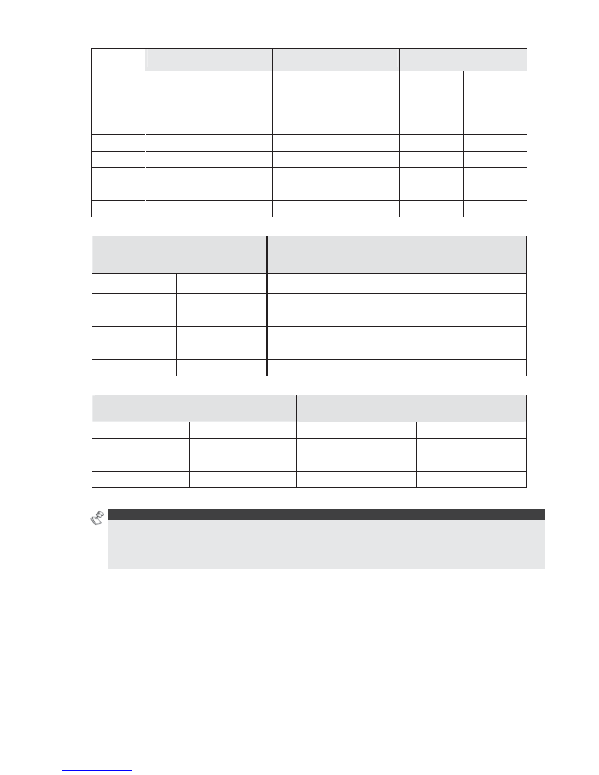
AWG
Gauge
Size
Wire Diameter Resistance: Feet Resistance: Meters
Inches Millimeters Ω Per F oo t Ω Per 1000
Feet
Ω Per Meter Ω Per 100
Meters
24 0.020 0.50 0.026 26.0 0.085 8.5
22 0.025 0.64 0.016 16.0 0.052 5.2
20 0.031 0.80 0.010 10.0 0.032 3.2
19 0.035 0.90 0.008 8.0 0.026 2.6
18 0.040 1.00 0.006 6.0 0.020 2.0
16 0.050 1.27 0.004 4.0 0.013 1.3
14 0.064 1.63 0.0025 2.5 0.008 0.82
Table A-1: Wire Facts
One-Way Wire Distance Between
ProSYS and Plug-In Transformer
AWG (American Wire Gauge)
For best results use the indicated wire size
or larger (numerically lower) size
In Feet In Meters 22 20 18 16 14
Up to 15 feet Up to 5 meters
15 - 25 feet 5 - 8 meters
25 - 40 feet 8 - 12 meters
40 - 60 feet 12 - 20 meters
60 - 100 feet 20 - 30 meters
Table A-2: Wiring Between the ProSYS Main Panel and the 16.5 VAC/40VA Plug-In Transformer
Wire Gauge
Max Combined Length of ALL Expansion BUS
Wiring
24 AWG 7/02mm 150 meters 492 feet
22 AWG 16/02mm 200 meters 656 fe et
20 AWG 24/02mm 333 meters 1092 fee t
19 AWG 28/02mm 400 meters 1312 fee t
Table A-3: Wire Gauge
NOTES:
For maximum system stability, it is best NOT to exceed a total of 300 meters (1000 feet) of wire when
wiring the Expansion BUS.
For a distance of more than 300 meters, refer to RISCO Group’s customer support service for detailed
information.

8 ProSYS Installation and Programming Manual
Total
Auxiliary
Power
(Max Current
Draw per
Branch)
Desired Wire Gauge in Particular Branch
32/02 mm
18 AWG
28/02 mm
19 AWG
24/02 mm
20 AWG
16/02 mm
22 AWG
7/02 mm
24 AWG
Max Run Max Run Max Run Max Run Max Run
Meters Feet Meters Feet Meters Feet Meters Feet Meters Feet
20mA 1195 3920 945 3100 750 2460 472 1550 296 970
30mA 793 2600 628 2060 500 1640 314 1030 197 646
40mA 597 1960 472 1550 375 1230 236 775 148 485
50mA 478 1568 378 1240 300 984 189 620 118 388
60mA 296 1300 314 1030 250 820 157 515 98 323
70mA 341 1120 270 886 214 703 135 443 84 277
80mA 299 980 237 775 187 615 118 388 74 243
90mA 264 867 209 687 166 547 105 343 66 215
100mA 239 784 189 620 123 492 94 310 59 194
Table A-4: Total Auxiliary Power
NOTE:
The wire lengths indicated represent the one-way distance between the source of power and the last detector
in the branch.
Max External
Siren Current
(Max current
draw per
branch)
Desired Wire Gauge in Particular Branch
32/02 mm 28/02 mm 24/02 mm 16/02 mm
Max Run Max Run Max Run Max Run
Meters F eet Meters Feet Meters Feet Meters Feet
100mA 238 780 191 625 151 495 94 310
200mA 229 390 95 313 76 248 47 155
300mA 79 260 63 208 50 165 31 103
400mA 59 195 48 157 38 124 24 78
500mA 48 156 38 125 30 99 19 62
650mA 37 120 29 96 23 76 15 48
Table A-5: Maximum External Siren Current
NOTE:
The wire lengths indicated represent the one-way distance between the ProSYS and the external siren in
the branch.
ProSYS Installation and Pr ogramming Manual 9
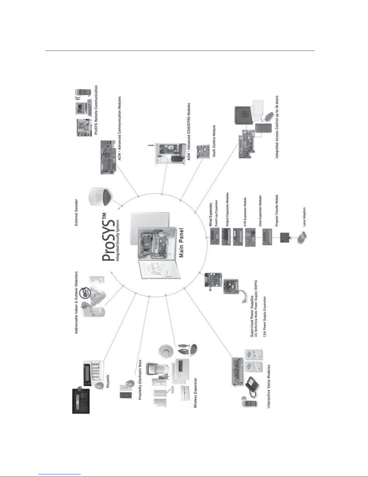
ProSYS Architecture and Capabilities
The following diagram provides an overview of the ProSYS's architecture and capabilities.
Examine this figure before beginning your ProSYS installation to obtain an overall picture of
the full extent of the ProSYS system's capabilities.
Figure 1: ProSYS Architecture and Capabilities

10 ProSYS Installation and Programming Manual
ProSYS Features
This section describes the features of the ProSYS system, including features specific to each
ProSYS model.
Feature-Specific Limitations
Each ProSYS model has several feature-specific limitations, as described in the following
table:
Feature ProSYS 16 ProSYS 40 ProSYS 128
Total Zones 8-16 8-40 8-128
Main Expansion Zones (wired
or wireless)
1x8
(EZ or WR)
4x8 or 2x16 or
2x8 + 1x16
(EX or WR)
1x8 + 7x16
(EX or WR)
Max BUS Zones 16 32 32
Max Current 1,5 A 1,5 A 1,5 A
Number of Expansion BUSes 2 2 2
Total Number of Expansion
Modules
64 (32 for ea ch data
BUS)
64 (32 for each data
BUS)
64 (32 for ea ch data
BUS)
Box NC Tamper Input 1 1 1
Bell Tamper EOL Input 1 1 1
Total Utility Outputs 6-22 6-38 6-70
Utility Output Expansion
Modules
Up to 2 modules
(max 16 UO)
Up to 4 modules
(max 32 UO)
Up to 8 modules (max
64 UO)
Partitions/Areas 4 4 8
Groups Per Partition/Area 4 4 4
User Codes 00-29 00-59 00-98
Access Control Modules
(# of Doors)
2 (4 doors) 4 (8 doors) 8 (16 doors)
Proximity Key Reader 16 16 16
Keypads 8 12 16
Accoun t Numbers 8 8 12
Follow Me Numbers 8 8 16
Event Log
256 Built-in (No
Possible Expansion)
512 (with Expansion) 999 (with Expansion)
GSM/GPRS Communication
Module
1 1 1
IP Communication Interface
(ACM)
1 1 1
NOTES:
The zone expansion modules can be either with wire or wireless.
All panels can work with a battery of up to 17AH according to the applicable regulations.
The relay output should have the option to supply COM positive -12V or negative -0V.

ProSYS Installation and Pr ogramming Manual 11
Main Panel
The Main Panel is the foundation of the system's operation and has the following features:
♦ 8 basic hardwired zones
♦ 6 Utility Outputs:
1 x relay (programmable output) (3 Amps)
1 x 500mA transistor (Open Collector)
4 x 70mA transistors (Open Collector)
♦ Box tamper input (normally open)
♦ Bell tamper input (using a 2.2KΩ end-of-line resistor)
♦ Two different 4-wire BUSes with "quick connectors" from the Main Panel, which is the
initial point for all system. If one BUS is shorted or there is any kind of problem that
interrupts the BUS data, the other one continues to operate normally
♦ Power for the operation of an external sounder
♦ Offers the required type of voltage for one or more electronic sirens, bells, or
loudspeakers, respectively
♦ Supports more than 20 zone types
♦ 6 zone terminations, including: closed-circuit (NC), open-circuit (NO), end-of-line
(EOL) resistors, double end-of-line (DEOL) resistors, triple end-of-line (TEOL)
resistors (refer also to Chapter 2, Mounting and Wiring the Main Panel) and BUS
zone.
♦ Event log (on board up to 256 events)
Zone Expansion
♦ Support for additional 16 (ProSYS 16), 32 (ProSYS 40) or 120 (ProSYS 128) wired or
wireless zones
♦ 8-Zone or 16-Zone wired/wireless-868MHz expansion modules
♦ 6 zone terminations, including closed-circuit (NC), open-circuit (NO), end-of-line (EOL)
resistors, double end-of-line (DEOL) resistors and triple end-of line(TEOL) resistors
♦ BUS zones support and BUS Zones expander
♦ Supports more than 20 zone types
♦ Forced setting zone capability
Wireless Devices
When using wireless zones, the ProSYS 8/16 Wireless expansion modules respond to
different wireless detectors, such as:
♦ PIR/PET detectors
♦ Smoke detectors
♦ Door contacts/Door magnet/universal transmitter/door contact +universal
♦ Up to 32 rolling code 4-buttons keyfobs
♦ Double key panic keyfob
♦ Flood detector
♦ Shock detectors
♦ CO detectors
♦ Gas detectors
♦ Glassbreak detectors
♦ External PIR WatchOUT detectors
The Wireless expansion module includes the following features:

12 ProSYS Installation and Programming Manual
♦ Super heterodyne technology
♦ Programmable supervision time
♦ Tamper detection
♦ Low battery in transmitters detection
♦ Signal jamming indication
♦ Programmable supervision time
Partitions/Areas
♦ Up to 8 independent partitions/areas
♦ Any zone can be assigned to any partition/area
♦ Each partition/area supports both zone sharing and cross zoning.
♦ Each partition/area can be assigned with its own account number
Groups
Groups are combined zones within a partition/area that are used for partial arming.
♦ Up to four groups of zones can be defined for each partition/area.
♦ Group arming is performed by using the Function keys on the keypad (A, B, C, and D).
Each key represents a different group of zones.
♦ Each zone can be assigned to any of the 4 groups
♦ Users can arm any of the four groups individually
♦ Group setting is performed by using the function keys on the keypad or using a keyfob
Keypads
The ProSYS can support up to 16 keypads, with a choice of four styles (LCD, two LED types,
and one LCD proximity type) from which virtually all system features can be accessed.
Figure 2: LCD Keypad
Each keypad is equipped with:
♦ Three Emergency Key zones (Panic, Fire, and Auxiliary Emergency)
♦ The ability to produce a Duress (Ambush) Code
♦ Double tamper-protected
♦ Internal buzzer
♦ Audible feedback for keypad operations
♦ Easy-to-use hot-key sequences for simple zone bypassing
♦ A one-key Quick-Arm feature for both "Stay" and "Away"
♦ In partitioned systems, keypads can be selectively assigned to specific partitions
♦ 4 function keys (A,B,C,D) can be programmed to carry a sequence of commands

ProSYS Installation and Pr ogramming Manual 13
User Codes and Authority Levels
♦ 1 engineer code
♦ 1 sub engineer code
♦ 1 Grand Master code
♦ Up to 99 user codes (ProSYS 128)
♦ 8 Authority levels
♦ Double code option for high security
♦ Codes can be defined to 4 or 6 digits (By default 6 digits)
Programmable Utility Outputs
♦ Supports additional 16 (ProSYS 16), 32 (ProSYS 40) or 64 (ProSYS 128) outputs
♦ 4-relay or 8-transistor expansion output modules
♦ Outputs operation follows system events, codes or scheduling programs.
♦ Output can follow up to 5 zone events (All/Any definition)
♦ X-10 Module: The ProSYS also supports the connection of an X-10 Transmitter
module to its 4-wire Expansion BUS. X-10 technology converts the ProSYS's
programmable output events into a protocol understood by the Transmitter module.
When triggered, this module generates activation and control signals along existing
AC premises wiring to the appropriate X-10 Receiver modules, appropriately placed
and connected within the premises to control lighting and appliances. X-10 Transmitter
modules are available for the ProSYS, supporting either 8- or 16-premises Receiver
modules.
Communication
♦ On-board Digital Communicator
♦ Numerous transmission formats to MS including ADEMCO Contact ID and SIA.
♦ Account number for each partition with additional backup accounts.
♦ 3 MS link up options using:
PSTN report
GSM report
IP report
GPRS report
SMS report
♦ Flexible split reporting for backup
♦ Call Save mode from which non-urgent reports can be collected over a designated
time period and then transmitted all at once (windowing), and support daily system
testing, along with reports of entry into, and exit from, the system's Installer
Programming mode
♦ Follow Me report: In addition to standard communication with the MS, the ProSYS
employs a Follow-Me feature in which the system can report a homeowner at work, or
a business owner at home, that there has been an alarm at a specific location by voice
message over the phone, SMS or Email.
Advanced Digital Voice Module
The Advanced Digital Voice module provides audible information about the status of your
ProSYS system and enables any remote, touch-tone (DTMF) telephone to act as a keypad
for the system. The Advanced Digital Voice Module can be used in the following situations:
♦ Upon event occurrence, such as alarm activation, the Advanced Digital Voice module
informs you of a security situation, such as intrusion or fire, by calling you and playing

14 ProSYS Installation and Programming Manual
a pre-recorded Event announcement. You can then acknowledge the event and
remotely operate the system.
♦ Remotely operating the system, which includes:
O Partition arming and disarming
O Zone bypassing
O UO activation/deactivation
O Changing Follow-Me numbers
O Performing Listen and Talk options that enable you to listen in to your property
and talk back, if necessary
Power Supply Expansion Module
Although the ProSYS's Main Panel provides 600mA of auxiliary power (900mA for Bell), the
use of a number of additional system modules and detectors will likely exceed this limitation.
As a result, the ProSYS permits the addition of up to eight remote Power Supply expansion
modules, each operating from AC power and connected to the BUS.
There are 2 types of power supply modules. One provides a total current capacity of 1.5
Amps and the other is a switched power supply that provides a total current capacity of 3
Amps. Both modules have connections for powering auxiliary devices and triggering bells,
electronic sirens, or loudspeakers during an alarm. Each Power Supply expansion module
also supports its own standby battery and is supervised for the loss of AC, a low battery
condition, tamper input, the failure of its auxiliary output power, and the loss of sounder loop
integrity.
Access Control Expansion Module
One of ProSYS's most unique features is its integration with an Access Control sub-system.
With a maximum connection of eight such Access Control modules, a total of 16 readers is
possible (each module supporting up to two readers). Each reader can operate with
magnetic, proximity, bar code, touch, and/or Weigand technology. Up to 999 users can be
accommodated, and up to 1000 "transactions" can be stored in a module.
Scheduling
Through the use of the system's built-in clock, it is possible to automate system operations at
the same time on selected days of the week or at a specific time within the subsequent 24hour period or during vacation periods.
The system operations include:
♦ Scheduling automatic arming and disarming (of one or more partitions).
♦ Scheduling automatic operation of Utility Outputs.
♦ Restricting users from disarming during predefined time periods.
Event Logging
The ProSYS has the capability of storing up to 999 significant events, including arming,
disarming, bypassing, alarms, troubles, restorals, and resets. These events are logged in
order according to date and time, and when applicable, according to Zone, Partition, Area,
User Code, Keypad, etc. When appropriate, such events can be displayed on an LCD keypad
or uploaded to the MS via the Upload/Download software and printed for further analysis.

ProSYS Installation and Pr ogramming Manual 15
Printer Module
A Printer module, designed to interface between the ProSYS's 4-wire Expansion BUS and a
Centronics-type parallel printer, enables the printing of all significant system events as they
occur, including access control activities, if applicable. Each event includes the date, time and
if applicable, the affected partition and the user involved.
Advanced Installation Tools
♦ Auto Installation: For quick and easy installation, the system performs automatic
installation of the modules connected to the BUS. The system searches for the
modules by automatically verifying their connection and operation through the BUSscanning feature and prompts the user to approve each module connection. The auto
installation feature is performed automatically after defaulting the system or can also
be performed manually.
♦ Self Monitoring
The BUS Test enables the system to verify the connection and the operation of
the modules connected to the BUS by indicating the efficiency of each one on a
0-100% scale. Each result is individually displayed on the LCD keypad (or via
the Upload/Download software).
A watchdog feature, which periodically and automatically performs a
comprehensive self-test and reports when operating faults are found.
A Maintenance Mode which, when selected, performs an active self-check on
many of its components.
One-man walk testing capabilities, enabling an Installer or technician to check
the operation of each contact and detector which, when tripped, produces
audible feedback and is visibly logged at the keypad from which the test was
initiated.
♦ System programming
Local keypad keys
Program Transfer Module: Used to store the programmed configuration of any
ProSYS without the need for power.
Local/Remote Upload/Download software
False Alarm Reduction
In an effort to deter false alarms, the ProSYS provides various programmable features,
including the following programmable features: cross zoning, swinger shutdown,
audible/visual entry/exit delays, fire alarm verification, dialer delay before an alarm
transmission, cancel report option, double knock, soak test and exit termination zone.
16 ProSYS Installation and Programming Manual
Chapter 2 Mounting and Wiring the
Main Panel
This chapter covers the first two steps of the ProSYS installation procedure, as
follows:
Step 1: Mounting the Main Panel, below
Step 2: Wiring the Main Panel, page 18
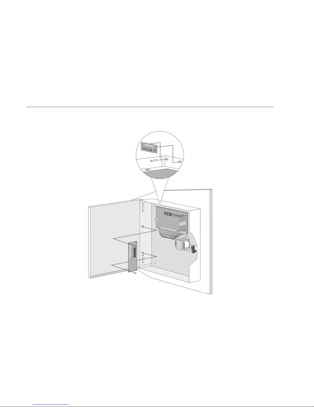
Step 1: Mounting the Main Panel
The ProSYS Main Panel . should be installed inside a metal box Attach the box to the
wall using the proper hardware, as shown below.
Figure 3: Mounting the Main Panel
The mounting location should be:
Dry.
Near an AC power supply (switched off).
With a good earth connection.
With access to the customer's phone lines.

ProSYS Installation and Pr ogramming Manual 17
Safety Precautions
When mounting the Main Panel, the following safety precautions are relevant:
When the Main Panel is powered on, mains voltage is present on the main PCB. To prevent
risk of electric shock, disconnect all power (AC transformer and battery) and phone cords
before servicing. Under no circumstances should mains power be connected to the PCB
other than to the main terminal block.
For AC mains connection, a readily accessible disconnect device shall be incorporated in the
building installation wiring.
The equipment should be installed in accordance with the National Fire Protection
Association's Standard #74 (N.F.P.A. Batterymarch Park, Qulncy, MA 02269) and local
National Electrical Codes.
For continued protection against risk of fire, replace fuses only with fuses of the same type
and rating.
There is a risk of explosion if a battery is replaced with an incorrect type. Dispose of used
batteries according to the proper instructions. (The Main Panel is designed to work with a
12 V, 7 Amp-hour sealed lead battery as a backup for the primary power supply.)
Do no short the terminals of the transformer together. This causes the internal fuse to blow.
The transformer must be connected to a 230 VAC, 24-hour outlet not controlled by a switch
other than an approved over-current protection device.
The Main Panel is designed with reverse polarity protection on the battery charging circuit.
However, prolonged improper connection of the battery to the Main Panel will result in
damage. The power should remain disconnected until all connections have been made
and checked for accuracy.
Discharging Static Electricity
Please note that it is important to discharge static electricity that may have built up in
your body before you touch a circuit. To do this, touch the earth. (Refer also to What
Makes a Good Ground? in Chapter 2, Mounting and Wiring the Main Panel.)
Following Local Regulations
Be sure to follow your local regulations regarding fire protection, electrical installation,
noise pollution, and security systems installation.
What Makes a Good Ground?
Grounding provides a degree of protection against lightning and induced transients for
any piece of electronic equipment that may, due to lightning or static discharge,
experience permanent or general malfunctions. The ideal ground is considered to be a
unified earth ground in which an 8-foot copper-clad rod, located close to the existing
power and telephone ground rods, is sunk several feet into the earth. Appropriate
hardware and clamps are then used to electrically connect each of these rods together
and then to the ground terminal of the device to be protected.
It may be possible to use an existing electrical ground on the premises if one is close
enough to the Main Panel. Ideally, that ground can be obtained at the metal service
panel where the incoming electrical power originates. When connecting the ground
wire, use a solid 14-gauge wire [or larger (numerically lower) size] connected between
the ProSYS's GND terminal and an acceptable electrical ground connection. Keep this
wire as short as possible and do not run it in conduit, coil it, bend it sharply, or run it
alongside other wiring. If you must bend it or change its direction, it should have a
radius of at least 8 inches at the point from which it is bent. If in doubt, you may want
to enlist the help of a licensed electrician in matters concerning such grounding.
18 ProSYS Installation and Programming Manual
Step 2: Wiring the Main Panel
This step explains the various wiring and connection procedures that must be
performed when wiring the Main Panel, as follows:
Wiring the Main Panel, page 18
Wiring the Zones to Sensors and Detectors (Zone Terminals Z1 through Z8), page 19
Wiring the Auxiliary Devices, page 22
Wiring the Bell Sounders, page 23
Wiring the Bell Tamper, page 23
Wiring the Box Tamper, page 24
Wiring External Triggerable Devices, page 24
Connecting the J10 Connector, page 25
Connecting to Ground (Earth), page 26
Connecting Telephone Lines, page 26
Jumper Settings, page 27
Connectors, page 28
Connecting AC Power, page 28
IMPORTANT: Before wiring the Main Panel, ensure that the connection to the power
supplies, mains or battery, is switched OFF during wiring.
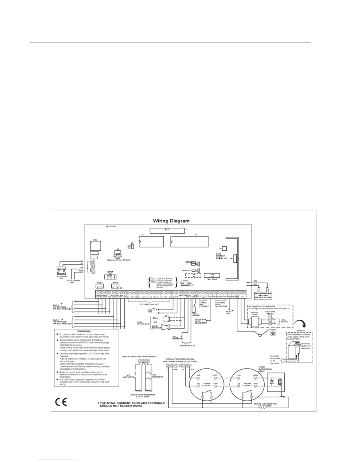
Wiring the Main Panel
Figure 4: Main Panel Wiring Diagram
ProSYS Installation and Pr ogramming Manual 19
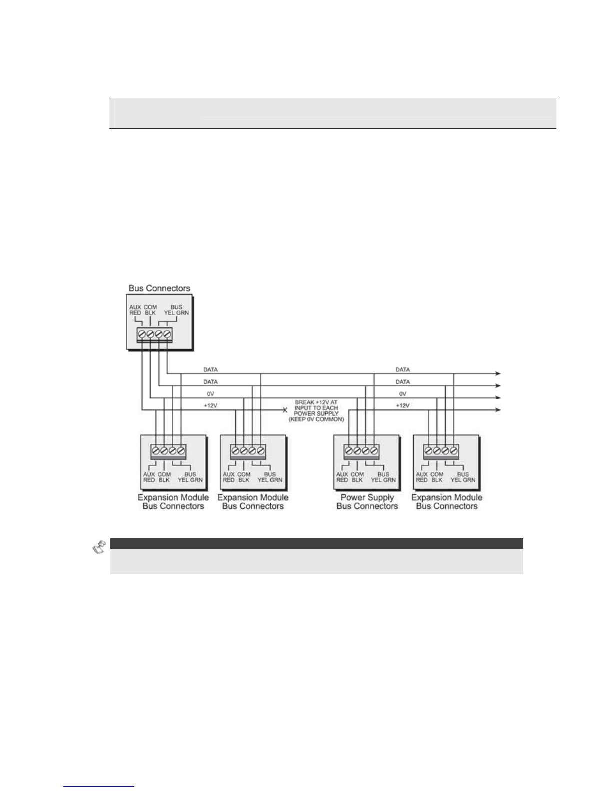
The second set of four terminals on the left of the Main Panel represent the Expansion
BUS. These support the connection of keypads and expansion modules.
The connections are terminal-to-terminal with color-coded wires, as follows:
BUS
Terminal
Description
AUX RED
+12V power for BUS expansion modules
COM BLK
Black 0V common for BUS expansion modules
BUS YEL
Yellow DATA connection for BUS expansion modules
BUS GRN
Green DATA connection for BUS expansion modules
To prevent a possible drop in voltage due to multiple keypads and long wire runs, use
a quality 4-conductor cable with an appropriate gauge size (refer to the table of gauge
sizes in Chapter 1, Introducing ProSYS).
The parallel wiring system supports parallel connections from any point along the
wiring (refer to
Figure 5 below). The maximum wire run permitted is 300 meters (1000
feet) for all legs of the BUS.
Figure 5: 4-Wire Expansion BUS
NOTE:
The ProSYS has 2 separate BUS connections. If one BUS is shorted or there is any kind of
problem that interrupts the BUS data, the other BUS will continue to operate normally.
Wiring the Zones to Sensors and Detectors
(Zone Terminals Z1 through Z8)
To wire the zones to sensors and detectors:
1 Connect up to 8 hardwired zones, using twisted-pair or 4-conductor cable wiring.
2 Connect each zone to the appropriate Zone (Z) terminal and its related COM terminal.
Each pair of zones shares a COM terminal. For example, Z1 and Z2 share a COM
terminal, as do Z3 and Z4, and so on.
20 ProSYS Installation and Programming Manual
NOTES:
It is recommended that you use an End-of-Line Resistor at the far end of each hardwired zone
to prevent short-circuits (16 resistors are supplied).
For a zone with a tamper switch, you can use a Double End-of-Line Resistor to save additional
Main Panel connections (refer to
Figure 6 on page 21).
3 Terminate unused zones at the Main Panel.
4 Connect the power to the sensors and/or detectors, as described in Wiring the Auxiliary
Devices, page 22.
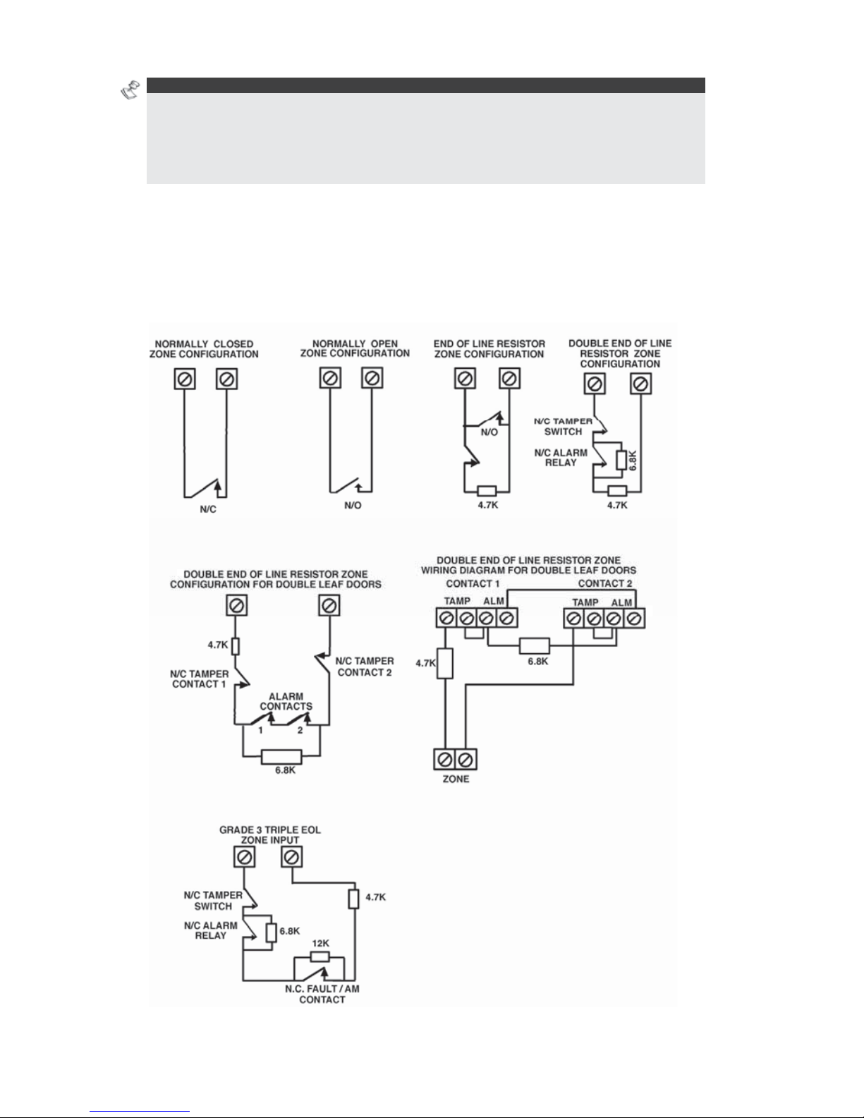
The following diagrams illustrate the various possible zone connections depending on
the zone expanders.
Connection on the main units or on the G3 zone expanders (ProSYS EZ8G3, EZ16G3):
ProSYS Installation and Pr ogramming Manual 21
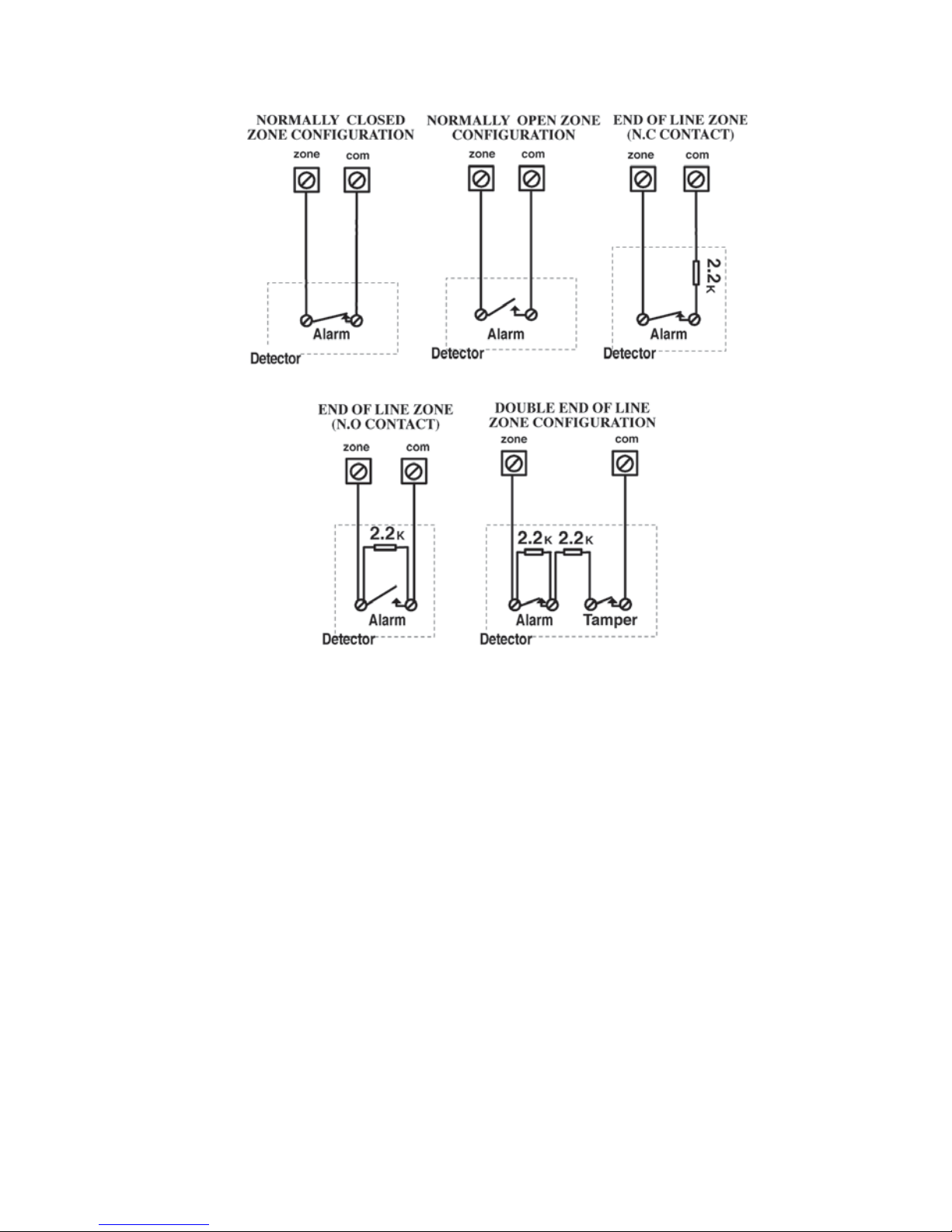
Connections on Zone Expanders (ProSYS EZ8, ProSYS EZ16):
Figure 6: Zone Connection Diagrams

22 ProSYS Installation and Programming Manual
The following table
indicates the EOL limit values when the ProSYS panel detects a status
difference. Please respect the EOL standard values given in the installation manual to prevent
unexpected alarms.
Zone Type
Impedance (KΩ)
Zone Mode
NO
47.1<R Ready
R<47.1 Trip
NC
6.97<R Trip
R<6.97 Ready
EOL
6.97<R Trip
3.07<R<6.97 Ready
R<3.07 Trip
DEOL
13.95<R Tamper
6.97<R<13.95 Trip
3.07<R<6.97 Ready
TEOL
47.1<R Tamper
19.92<R<47.1 Anti Mask
13.95<R<19.92 Fault
6.97<R<13.95 Trip
3.07<R<6.97 Ready
R<3.07 Tamper
TEOL uses normally-closed (NC) contacts in a zone to distinguish between alarm, tamper
condition and fault/AM condition using 4.7K and fault/AM condition using 4.7KΩ + 6.8KΩ +
12KΩ End-of-Line resistors.
Wiring the Auxiliary Devices
To wire auxiliary devices:
Use the Auxiliary Power AUX (+) COM (-) terminals to power PIRs, glass-break detectors
(4-wire types), smoke detectors, audio switches, photoelectric systems and/or any device
that requires a 12V DC power supply.

ProSYS Installation and Pr ogramming Manual 23
NOTES:
The total power from the AUX terminals should not excee d 600mA.
To connect a 4-wire smoke detector or devices that require resetting after an alarm condition,
connect the Auxiliary power AUX and UO terminals (refer to Figure 4 on page 18, for smoke
detector wiring). Remember to define the UO as Switched Auxiliary (refer to the Switch AUX
parameter described in Chapter 5, Quick Key [3][1][14]). Using the Installer Programming
Menus).
In addition, when connecting a 4-wire smoke detector, observe the wiring guidelines mentioned
in the previous sections, along with any local requirements applicable to smoke detectors.
To prevent a possible drop in voltage due to current requirements and distances involved,
make sure to use the appropriate wire gauge (refer to the table of gauge sizes in Chapter 1,
Introducing ProSYS).
To incre ase your power supply when employing multiple auxiliary devices, you can use the
optional Pow er Supply expansion module (refer to the Wiring Power Supply Expansion
Modules section in Chapter 3, Installing External Modules and Devices).
If the auxiliary outputs are overloaded (exceed 600mA) and are shut down, you must
disconnect all loads from the outputs for a period of at least 10 seconds before you reconnect
any load to the auxiliary outputs.
Wiring the Bell Sounders
To wire the bell sounders:
1 Connect a suitable wire to the internal sounding device(s) inside the building (bell, electronic
siren, or loudspeaker).
2 Ensure that you note the polarity when connecting electronic siren(s) and/or polarized bells.
!
WARNING:
To avoid Bell Loop Trouble, if NO connection is made to an internal sounder, use a 2200Ω
resistor in its place.
NOTE:
It is important to position the BELL/LS Jumper (J3) correctly. The position varies depending
on the type of internal sounder.
3 For a loudspeaker without a built-in sound driver, position the jumper J3 so that it covers both
pins. The Main Panel produces a continuous oscillating voltage for burglary and panic alarms
and an interrupted oscillating voltage for fire alarms.
4 For a bell or an electronic siren with a built-in sound driver, position the jumper J3 so that it
does NOT cover both pins. A steady 12V DC is produced at the sounder terminals during
burglary and panic alarms. A slow pulsing voltage is produced during a fire alarm.
Wiring the Bell Tamper
To wire the bell tamper:
Connect the bell tamper to the BELL TMP and COM terminals on the Main Panel, as
illustrated in
Figure 4: Main Panel Wiring Diagramon page 18.
24 ProSYS Installation and Programming Manual
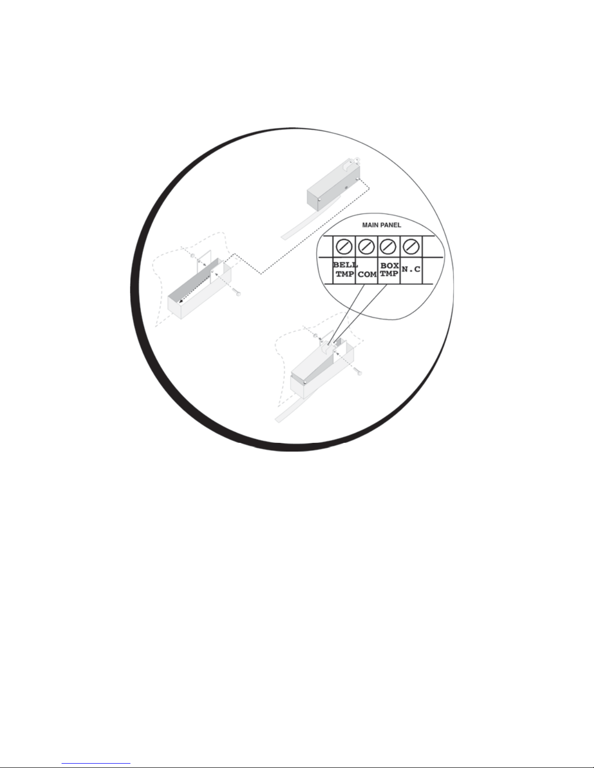
Wiring the Box Tamper
To wire the box tamper:
Connect the box tamper to the BOX TMP and COM terminals on the Main Panel, as
illustrated in
Figure 4 on page 18. Refer also to the diagram shown below.
Figure 7: Wiring the Box Tamper
Wiring External Triggerable Devices
To wire external triggerable devices:
Wire the external triggerable devices that you want to activate to the outputs UO1-UO6, as
follows:
O UO1: Refer to the J10 connector instructions, described in the next section. For
additional details, refer to Chapter 3, Installing External Modules and Devices.
O UO2-UO6: Connect the positive connection of the device to AUX (+) and the
negative connection to the UO's (-) terminals.
ProSYS Installation and Pr ogramming Manual 25
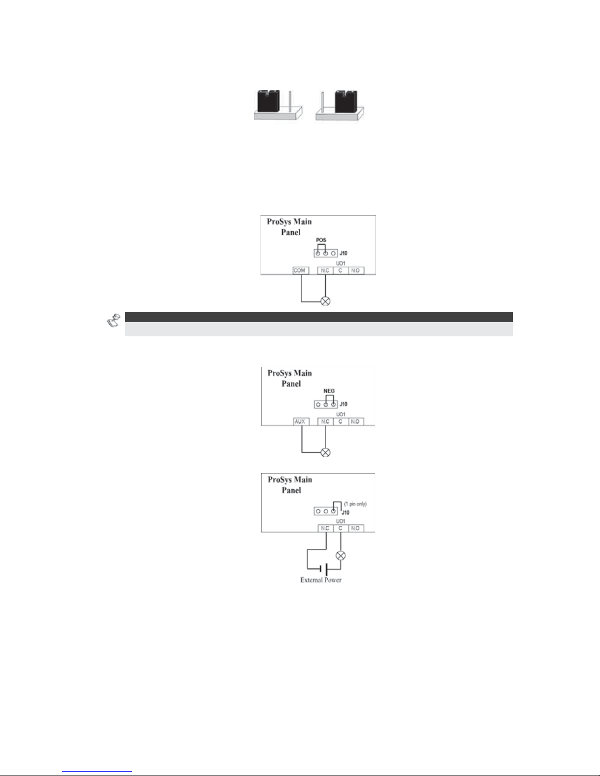
Connecting the J10 Connector
POS NEG
Figure 8: Connecting the J10 Connector
The J10 connector (jumper) determines the UO1 connection (behavior), which is
normally used for an external siren connection, as follows:
Positive (POS): When the J10 connector is placed on POS, the C terminal on UO1 receives
13.8V.
NOTE:
The maximum current for UO1 and the bell should not exceed 900mA.
Negative (NEG): When the J10 connector is placed on NEG, the C terminal on UO1 receives
COM.
If the J10 connector is placed only on 1 pin, the UO1 acts as a dry contact.
26 ProSYS Installation and Programming Manual
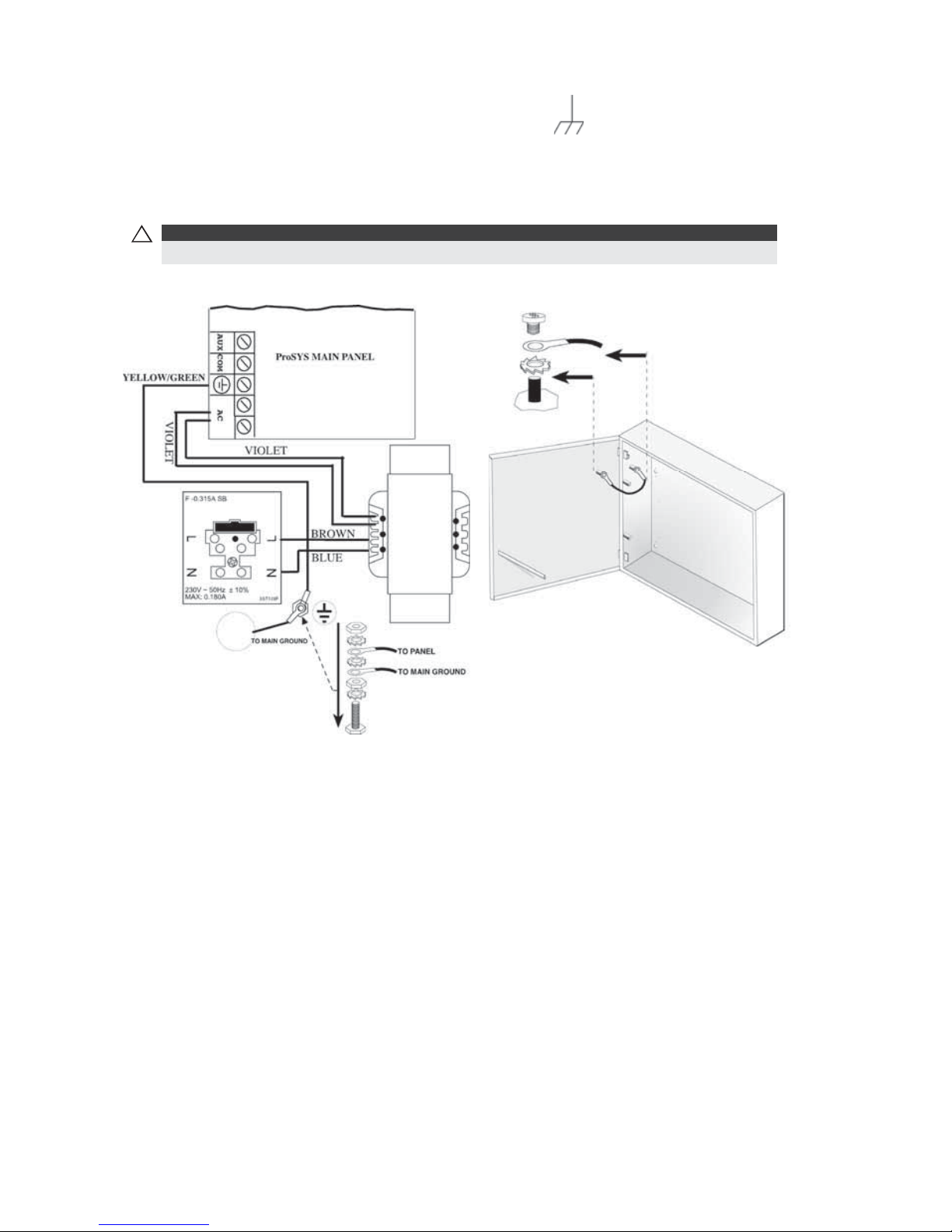
Connecting to Ground (Earth)
To connect to ground (earth):
Connect the metal box and the door of the metal box to mains earth (ground), as shown in
the diagrams on the following page. Refer also to What Makes a Good Ground?, page 17.
!
IMPO RTA NT:
Connecting to ground must be performed according to the local National Electrical Code.
Figure 9: Grounding the Metal Box Figure 10: Grounding the Metal Box
Door
Connecting Telephone Lines
These lines are typically derived from an installed RJ31X jack.
To connect telephone lines:
1 Connect the incoming telephone line to the Main Panel's LINE terminals.
2 Connect any telephone on the premises to the SET terminals.

ProSYS Installation and Pr ogramming Manual 27
Jumper Settings
The ProSYS is equipped with internal jumpers. Use the following table to configure the
jumpers according to the desired configuration.
Jumpers Po
siti
on
Function
DEFAULT (J2)
Enables to default the panel and restore the ProSYS
codes (Grand master, installer and sub installer) to the
manufacturers default settings.
Position the jumper plug over both pins when
reinstating factory installed defaults values to the
Grand master, installer and sub installer codes or for
installing programming using the Program Transfer
Module (refer to Chapter 4, Programming the
ProSYS).
(Default)
Maintains the last programming setting and disables
the restoring of the ProSYS codes (Grand master,
installer and sub installer) to the manufacturers default
settings.
Position the default jumper plug over one pin for
safekeeping.
BELL/
LOUDSPEAKER
(J3)
The J3 jumper determines whether a bell or
loudspeaker sound will be heard.
Loudspeaker: The ProSYS produces a continuous or
interrupted oscillating voltage, depending on the type
of alarm.
(Default)
Bell: The ProSYS produces a steady 12V DC voltage
or a slow pulsating voltage, depending on the alarm
type. Refer to Wiring the Bell Sounders, page 23, for
further details
BATTERY
PROTECTION
(J20)
(Default)
Battery Discharge Protection is Activated: If a
continuous AC power outage occurs, the ProSYS
automatically disconnects the battery when its backup
battery voltage drops below 10.05 VDC, in order to
prevent "deep discharge” that may damage the
battery.
NOTE :
In this position, the ProSYS will not start to operate from
a battery power supply, unless connected to the Mains
first.
Battery Discharge Protection is Disabled; The battery
may be totally discharged during continuous AC
failure, thus battery replacement may be required (no
deep discharge protection).
NOTE :
In this position, the ProSYS will start to operate from a
battery power supply whether it is connected to the
Mains or not.

28 ProSYS Installation and Programming Manual
Jumpers Po
siti
on
Function
UO1 (J10)
Determines the UO1 connection (behavior), see
Connecting the J10 Connector, page 25.
Default: 1 PIN
Connectors
Connector Function
J1, J5
BUS 1 Plug in connector.
J8
BUS 2 Plug in connector.
J4
SIG In connector. The J4 SIG IN voice connector enables the
transfer of audio data between the Voice module RP200VC and
the phone line.
J6
The J6 connector is used to connect the Advanced Digital Voice
Module (rp128ev00uka) to the ProSYS.
Connect the Voice module to the VOICE connector (J6) on the
Main Panel via the supplied cable. This connector transmits
signals from the Voice module to the telephone line during remote
communication and is essential for normal operation of the Voice
module.
Connecting AC Power
To connect AC power:
1 Connect the 230V AC to the mains fuse (SLOW BLOW 315 mA) input terminal block
according to the Local National Electronic Code.
2 Fasten the AC cord to the metal bo x using adjustable clamps.
!
IMPORTANT:
Do NOT apply mains power at this time.
Be sure to connect the live wire of the AC power through the AC fuse. The size of the conductors
must not be less than 0.75mm2 (18AWG).

ProSYS Installation and Pr ogramming Manual 29
Chapter 3 Installing External
Modules and Devices
This chapter describes steps 3 to 5 of the ProSYS installation procedure, as follows:
Step 3: Identifying and Wiring Keypads and Expansion Modules
Step 4: Adding Modules, page 31
Step 5: Applying Power, page 35
Step 3: Identifying and Wiring Keypads and
Expansion Modules
This section explains how to program a unique ID number to identify each keypad and
expansion module in the system and how to install a keypad, as follows:
Programming Device ID Numbers, below
Installing a Keypad, page 30
Programming Device ID Numbers
To program device ID numbers:
Program each device's ID number by setting the dip switches, as follows:
I 1 2 3 4
01
OFF OFF OFF
OFF
02
ON OFF OFF
OFF
03
OFF ON OFF
OFF
04
ON ON OFF
OFF
05
OFF OFF ON
OFF
06
ON OFF ON
OFF
07
OFF ON ON
OFF
08
ON ON ON
OFF
09 OFF OFF OFF ON
10 ON OFF OFF ON
11 OFF ON OFF ON
12 ON ON OFF ON
13 OFF OFF ON ON
14 ON OFF ON ON
15 OFF ON ON ON
16 ON ON ON ON
Figure 11: Dip Switch Settings
Assign the same ID numbers to the different
categories of devices (meaning keypads and
expansion modules) in the order they are
added to the system.
This means that you must assign the ID of 01
to the first keypad as well as to the first Zone
Expander, the first Utility Output and the first
Power Supply module. A second module in
any of these categories receives the ID of 02.
Up to 16 keypads can be added to the system,
each assigned ID numbers from 01 to 16. Up
to 8 of the other types of devices can be
added to the system, each assigned ID
numbers from 01 to 08.
30 ProSYS Installation and Programming Manual
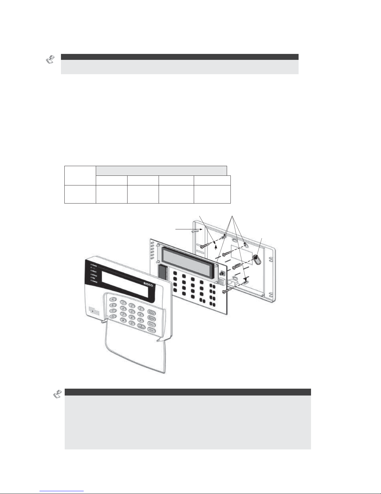
Installing a Keypad
NOTE:
For information on installing the Touchscreen keypad, refer to the ProSYS Touchscreen Keypad
Instruction manual that is incl uded with the product.
To install a keypad:
1 Open the Keypad Cover: Remove the back of the keypad cover, and using a
screwdriver, press in each of the retaining clips to separate the back cover from the
keypad. Take care not to touch the circuitry of the keypad buttons.
2 Set the Dip Switches: Program the keypad ID by setting the dip switches according to
the table displayed in
Figure 11 on page 29. Dip switch settings are per ID number
(01 = first keypad, 02 = second keypad, and so on).
3 Connect the BUS Wiring: Connect the wires from the appropriate terminals in the
keypad to the appropriate connector on the Main Panel's Expansion BUS terminals.
The connections are terminal-to-terminal with the terminals clearly marked. The wires
are color-coded, as follows:
UP
Orientation arrow
Wall fixing points
Back panel
Tamper protected fixing
point
Figure 12: Keypad Installation Front View
NOTE S:
A trimmer is located on the right side of the keypad (next to the dip switches) that enables you
to adjust the brightness and contrast of the LCD display. Therefore, it is recommended to leave
the keypad open while powering up in order to adjust the LCD display.
To prevent a possible drop in voltage due to multiple keypads and long wire runs, use a quality
4-conductor cable with an appropriate gauge size (refer to the table of gauge sizes in Chapter
1, Introducing ProSYS).
The maximum wire run permitted is 300 meters (1000 feet) for the total BUS wiring.
EXPANSION BUS TERMINALS
AUX COM BUS BUS
Color
RED BLK
(Black)
YEL
(Yellow)
GRN
(Green)

ProSYS Installation and Pr ogramming Manual 31
4 Set the Tamper Switch: Before mounting the keypad on the wall, locate the
rear-mounted Tamper Switch and make sure that it is vertically oriented.
5 Replace the Cover:
O Carefully replace the keypad's printed circuit board in its cover.
O Join the cover and base by hooking the tops together and then snapping the bottom in
place, returning the retaining clips to their positions.
Step 4: Adding Modules
This section explains how to add the various ProSYS modules, as follows:
Wiring Zone Expansion Modules, below
Wiring Utility Output Modules, page 32
Wiring Power Supply Expansion Modules, page 34
Wiring Additional Modules, page 35
Wiring Zone Expansion Modules
Figure 13: 8 Zone Expansion Module Figure 14: 16 Zone Expansion Module
To wire Zone expansion modules:
1 Set the Dip Switches: Assign a unique ID to each Zone expansion module by setting
the dip switches, using Jumper Settings on page 29.
NOTE:
The ID for the first Zone expansion module is 01, for the second 02, and so on.
2 Connect the BUS Terminals: Connect the first four terminals at the left of the Zone
expansion module to the Main Panel's 4-wire BUS terminal, as follows:
EXPANSION BUS TERMINALS
AUX COM BUS BUS
Color
RED BLK
(Black)
YEL
(Yellow)
GRN
(Green)
NOTES:
The parallel wiring system supports pa ra llel connections from any point along the wiring (refer
to Chapter 2, Mounting and Wiring the Main Panel).
The maximum wire run permitted is 300 meters (1000 feet) for the total BUS wiring.
3 Connect the Zone Terminals (8-Zone Expander Z1-Z8; 16-Zone Expander Z1-Z16): Refer
to steps 1 to 3 in the Wiring the Zones to Sensors and Detectors section in Chapter 2,
Mounting and Wiring the Main Panel.
4 Supply Po wer to the Aux iliary Devices: Refer to step 4 in the Wiring the Zones to Sensors
and Detectors section in Chapter 2, Mounting and Wiring the Main Panel.

32 ProSYS Installation and Programming Manual
Wiring Utility Output Modules
Figure 15: Utility Output Module UO4 (Showing an Example of UO4 Wiring)
Figure 16: Utility Output Module E08 Figure 17: Utility Output Module X-10
To wire Ut ility Output modules:
1 Set the Dip Switches: Assign a unique ID to each Utility Output expansion module by setting
the dip switches, using
Figure 11 on page 29.
NOTE:
The ID for the first Utility Output expansion module is 01, for the second 02, and so on. The
first Utility Output in the Utility Output expansion module (defined as ID 01) will always be Utility
Output 07.
2 Connect the BUS Terminals: Connect the first four terminals at the left of the Utility
Output expansion module to the Main Panel's 4-wire BUS, as follows:
EXPANSION BUS TERMINALS
AUX COM BUS BUS
Color
RED BLK
(Black)
YEL
(Yellow)
GRN
(Green)
3 Set the Tamper (TAMP COM): The Utility Output expansion module can be contained in
a metal cabinet. Tamper the cabinet, as follows:

ProSYS Installation and Pr ogramming Manual 33
O Connect one (or more) normally open (NO) momentary-action pushbutton switches
in a series between the TAMP and COM terminals in order to short-circuit these
terminals while the cabinet door is closed.
NOT ES:
It is not necessary to use a tamper switch if another module sharing the same cabinet is
equipped with one .
Do NOT use an End-of-Line Resistor in the tamper switch circuit.
O If a tamper switch is not used, connect a wire jumper between the two terminals.
4 Mount the Utility Output Expansion Modules: Mount one or more Utility Output
expansion modules in the Main Panel cabinet, depending on space availability.
Alternativ ely, mount them in a separate cabinet.
5 Connect the Triggerable Device to the Utility Output:
O Connect one wire to the COM terminal of the UO device to be operated and connect the
other wire to the GND.
O Connect the NO or NC switch to the AUX terminal.
6 Wire the Relay Connections: The Relay module has 4 relays (UO1, UO2, UO3, and
UO4), which can be connected as follows:
O Connect one wire of the device to be operated to the UO terminal.
O Connect the other wire of the device to be operated to the AUX terminal.
For instructions about programming the relay operation, refer to the Utility
Output section in Chapter 5, Using the Installer Programming Menus.
7 Wire the Triggers: The Open Collector modules have 8 outputs (UO1 through UO8).
For instructions about programming their operation, refer to the Utility Output section in
Chapter 5, Using the Installer Programming Menus.
8 Wire the X-10:
O Connect the 4-wire BUS between the Main Panel and the X-10 module.
O Connect an RJ25 cable (4-wire telephone cable) between the RJ11 connector on the
X-10 module and the X-10 transmitter.
O Plug the X-10 transmitter into the AC power.
O Plug the X-10 receiver into the AC power close to the device that will be operated.
O Connect the X-10 receiver to the device.
For more information about programming and setting the ID of the X-10
module, refer to the instructions supplied with the module
34 ProSYS Installation and Programming Manual
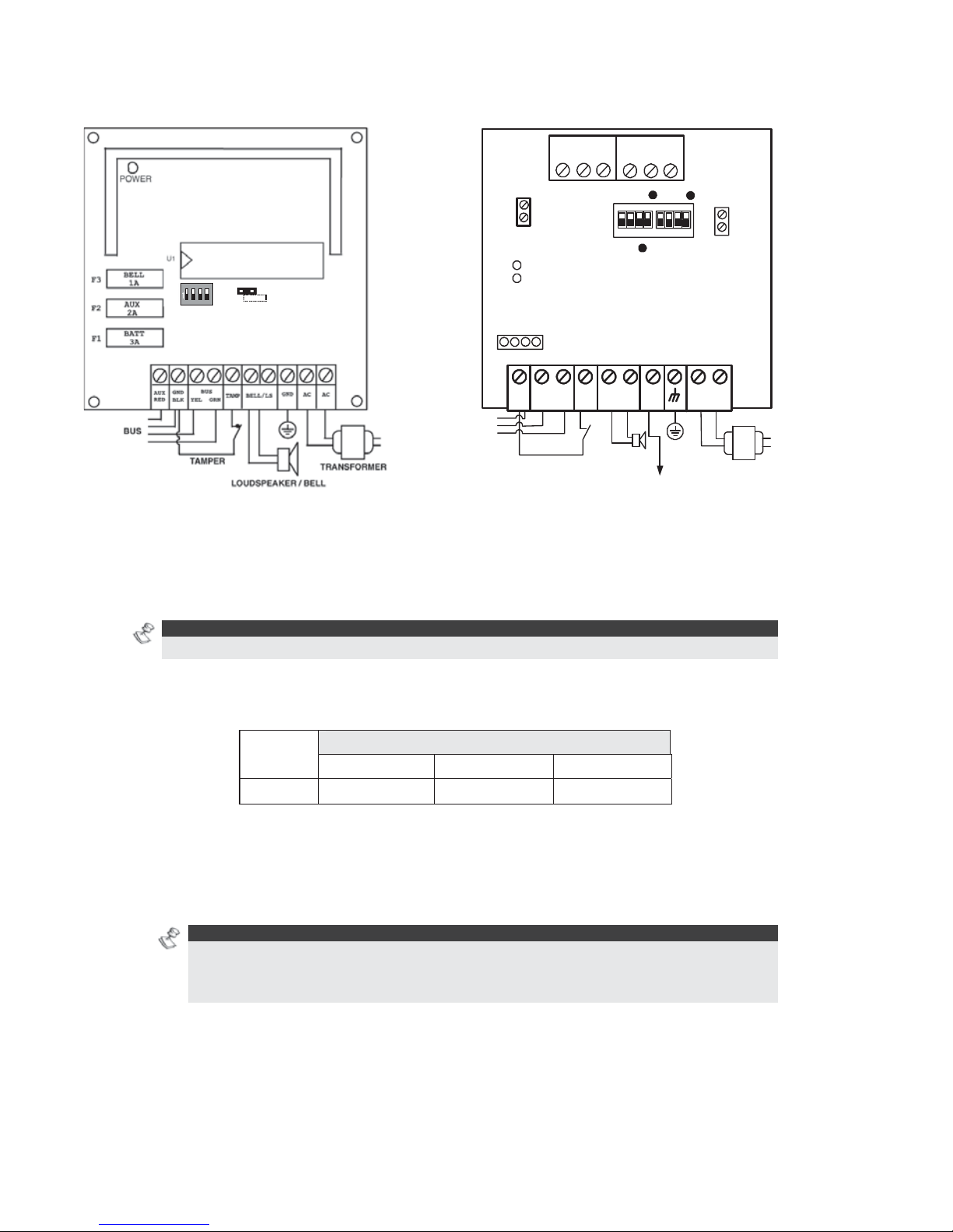
Wiring Power Supply Expansion Modules
ON
1234
ON
OFF
SW1
BELL
LS
(PS LED)
(UO LED)
AC
AUX
RED
BELL LS
+ -
TAMP
BUS
YEL GRN
COM
BLK
BUS
BELL/ LS
(Bell/Loudspeaker
Jumper)
OC
(Over Current LED)
BAT
(Battery Jumper)
PS
Battery
Connections
Loudspeaker/
Bell
Power to Accessories
and Detectors
Transformer
1234
1234
ON
N.O
N.C
C
UO 1
C
UO 2
N.O
N.C
Figure 18: 1.5A Power Supply Module PS Figure 19: 3A Power Supply Module PS
To wire Power Supply expansion modules:
1 Set the Dip Switches: Assign a unique ID to each Power Supply e xpansion module
by setting the dip switches, using
Figure 11 on page 29.
NOTE:
The ID for the first Power Supply expansion module is 01, for the second 02, and so on.
2 Connect the BUS Terminals: Connect only three of the first four terminals at the left of
the Power Supply e xpansion module to the Main Panel's 4-wire BUS, as follows (refer also
to Figure 2-3 in Chapter 2, Mounting and Wiring the Main Panel):
EXPANSION BUS TERMINALS
COM BUS BUS
Color
BLK (Black) YEL (Yellow) GRN (Green)
3 Set the Tamper (TAMP COM): The Power Supply e xpansion module can be contained in
a metal cabinet. Tamper the cabinet, as follows:
O Connect one (or more) normally open momentary-action pushbutton switches in a
series between the TAMP and COM terminals.
NOT ES:
It is not necessary to use a tamper switch if another module sharing the same cabinet is
equipped with one.
Do NOT use an End-of-Line Resistor in the tamper switch circuit.
O If a tamper switch is not used, connect a wire jumper between the two terminals.
4 Connect the Internal Siren BELL/LS (+) (-):
O Connect a suitable wire to the internal device(s) to be driven by the Power Supply
expansion module (bell, electronic siren, or loudspeaker).

ProSYS Installation and Pr ogramming Manual 35
O Use a larger wire gauge if the distance separating the siren and the module is
significant. Take the siren(s) current draw into account as well when selecting a wire
gauge (refer to the table of gauge sizes in Chapter 1, Introducing ProSYS).
NOTE:
Any internal siren(s) connected to the Power Supply expansion module will operate exactly
like the siren(s) connected to the Main Panel.
O Position the BELL/LS Jumper (J3), as follows:
♦ For a loudspeaker without a built-in siren driver, position the jumper J3 so that it
covers both pins. The module produces a continuous oscillating voltage for
burglary and panic alarms and an interrupted oscillating voltage for fire alarms.
♦ For a bell or electronic siren, with a built-in sound driver, position the jumper J3 so
that it does NOT cover both pins. A steady 12V DC is produced at the siren
terminals during burglary and panic alarms. A slow pulsing voltage is produced
during a fire alarm.
5 Supply Power to the Auxiliary Device AUX (+) COM (−): The Power Supply
expansion module can power PIRs, glass-break detectors (4-wire types), audio
switches, and photoelectric systems. It can also power any device located too far from
the Main Panel and/or whose operation requires a continuous supply of 12V DC via
the AUX (+) and COM (−) terminals. (Refer to Chapter 2, Mounting and Wiring the
Main Panel).
6 Connect the Flying Leads (RED and BLACK): Connect these leads (at the proper
time) to the positive (+ RED) and negative (− BLACK) terminals of the appropriate
Standby Battery for the Power Supply expansion module.
Wiring Additional Modules
For details about wiring the following modules, refer to the installation and
programming manual that is supplied with each module:
Advanced Digital Voice Module
Access Control Module
Proximity Key Reader
Fast PSTN Modem 2400 BPS
ProSound Sounder
Advanced Communication Module (ACM)
GSM/GPRS Module (AGM)
BUS Zones detectors (WatchOUT, Lunar Industrial, WatchIN, iWise)
BUS Zone Expander
Step 5: Applying Power
After you have completed wiring the modules, you can apply power and program the
system according to the instructions in the next chapter.

36 ProSYS Installation and Programming Manual
Chapter 4 Programming the ProSYS
This chapter explains the ProSYS programming options, how to use the keypad elements,
and the basics about programming via the keypad, as described in the following sections:
Using the ProSYS Main Panel Programming Options, below
Using the LCD Keypad, page 37
Programming from the LCD Keypad, page 38
Using the Program Transfer Module, page 43
For detailed information about each Programming option, refer to Chapter 5, Using the
Installer Programming Menus.
Using the ProSYS Main Panel Programming
Options
You can program the ProSYS in any of the following ways:
LCD Keypad: Use any of the LCD keypads described in this manual. Each keypad needs a
unique ID to identify it in the system. Refer to Chapter 3, Installing External Modules and
Devices, for details about how to set the keypad ID using dip switches. Instructions for
programming the ProSYS from an LCD keypad are provided on pages 37 through 42.
Program Transfer Module (PTM): (Model ProSYS EE) The PTM is a tiny circuit board into
which a copy of the Main Panel's configuration can be copied and stored as well as
transferred to any installation when temporarily plugged into its 4-wire BUS. Refer to page
43 for detailed instructions about using the Program Transfer Module.
Upload/Download (U/D): This is a software application that enables you to program the
ProSYS from a PC computer. It offers the following two alternatives:
O Working locally, through a portable computer connected to the Main Panel
O Working at a remote site, communicating with the Main Panel via one of the following
options:
O A phone line and modem
O TCP/IP network using the ACM module
O GPRS using the AGM a phone line and modem
O When using the Upload/Download software, the following is required:
O IBM compatible PC
O Upload/Download software
O BUS adapter cable and plug to connect between the PC serial COM port and the
ProSYS J1 connector (for on-site use)
O Modem with access to a phone line (for remote use)
O USB/485 converter for on-site use (p/n RP128EUSB00A) to connect between a
PC USB port and the ProSYS J1 serial connection. For additional details, refer
to a RISCO Group’s technical support representative.
Full details and operating instructions for the U/D software are available in the
Upload/Download User's Manual, provided with the software (p/n 5IN128UD).

ProSYS Installation and Pr ogramming Manual 37
Using the LCD Keypad
#/
?
Figure 20: The LCD Keypad Face
The LCD keypad is a visual interface tool that helps you operate the ProSYS Main Panel. The
LCD keypad contains six LED indicators and a variety of keys. Their typical uses are
described in the following table:
NOTE:
For information regarding the TouchScreen keypad please refer to the instructions supplied with the
product.
Item Key/LED Programming Mode/Function
1 Power LED
This LED indicates the following:
• LED ON = power on
• Slow flashing LED = an active programming session
• Fast flashing LED = system trouble
2 Arm LED
This LED indicates that the system is armed. All partitions must
be disarmed (LED unlit) to enter the Installer Programming
mode.
3 Ready LED
These LEDS are off (unlit) during programming operations.
These LEDs on the keypads (other than the one being used for
actual programming) flash during programming operations.
4 Bypass LED
5 Fire LED
6 Tamper LED

38 ProSYS Installation and Programming Manual
Item Key/LED Programming Mode/Function
7 A, B, C, and D
Use these keys for defining groups and macros. Refer to the
Groups section in Chapter 1, Introducing ProSYS for further
details.
8
Use this key to exit the current programming selection and
move up to the next higher level in the programming hierarchy.
9 LCD Program
Display
The LCD program display consists of two lines. The top line
displays information about the main selection mode, and the
bottom line displays information and/or data about the specific
option set. Such data may be changed through keypad entry.
When programming, up to 16-characters can be entered into a
line, as required.
10 0 through 9 Use the numbered keys, 0 through 9, to key in numbers and/or
special characters when labeling zones, areas, and partitions.
(For information about how to use the keypad for labeling
zones, areas, and partitions, refer to Chapter 5, Using the
Installer Programming Menus.)
11
/
/
Press either one of these keys to move back and forth through
the programming level functions.
These keys also change the position of the flashing cursor.
When editing a selection, the cursor moves to the left or right
respectively.
12
/
Use this key to toggle forward through the programming
choices within a selection.
13
/
Use this key to toggle backward through the programming
choices within a selection.
14
/
Use this key to enter selected information into the system or to
accept the current selection and access the lower level of
options in the programming hierarchy.
Programming from the LCD Keypad
This section explains how to use the keypad to access the Installer Programming menu as
well as how to restore the manufacturer's defaults, as described in the following sections:
Accessing the Installer Programming Menu, below
Restoring Manufacturer's Programming Defaults, page 41
Keypad Timeout, page 43
Using the Program Transfer Module (PTM), page 43
Accessing the Installer Programming Menu
This section describes how to access the Installer Programming menu for the first time or
after the Main Panel has been defaulted, as well as how to access it from the regular
operation mode.
If the Main Panel has been defaulted, you must enter the Installer Programming menu as if it
is the first time. In this case, after you enter your Installer code, the system automatically
enters the automatic accessories setting process by performing the BUS scan. (Refer to the

ProSYS Installation and Pr ogramming Manual 39
Accessories: Auto Settings section of Chapter 5, Using the Installer Programming Menus for
further details).
To access the Installer Programming Menu for the first time (or after the
Main Panel has been defaulted):
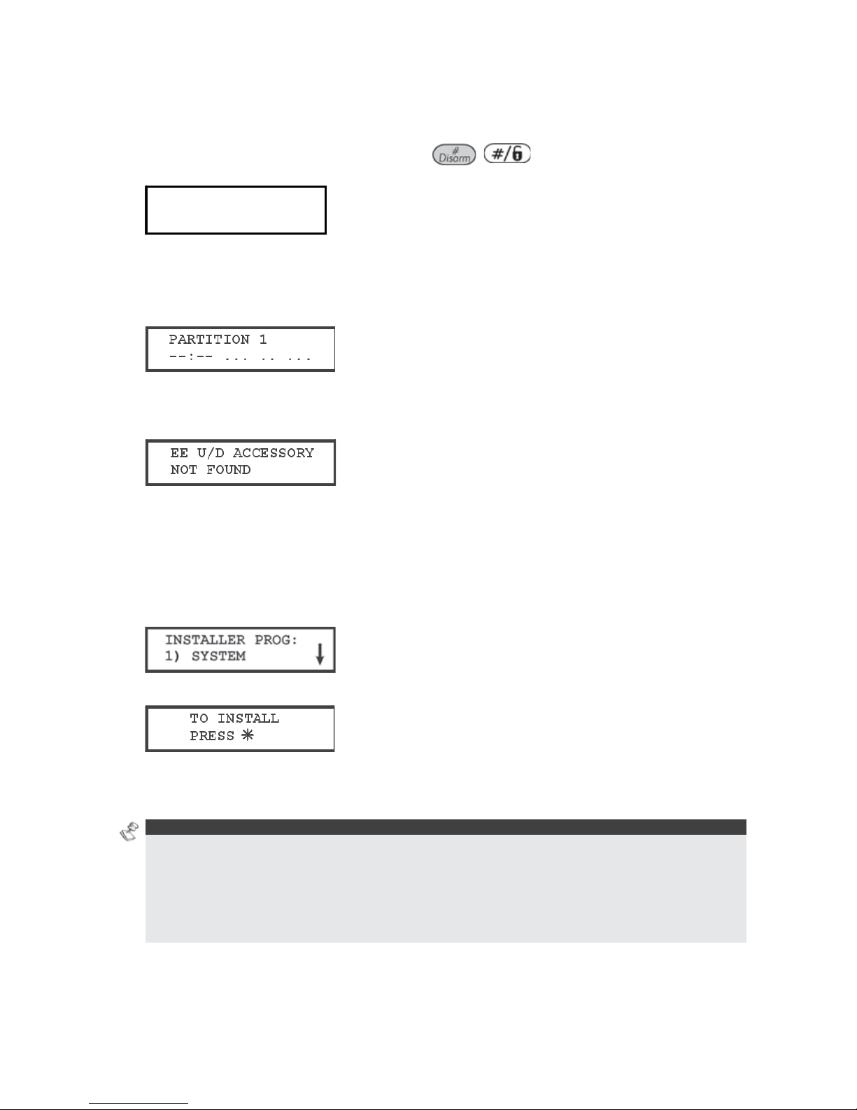
1 When you power up the system, the following display appears:
PLEASE WAIT…PLEASE WAIT…
After a brief wait, the following display appears:
TO INST ALL
TO INST ALL
PRESS *
PRESS *
TO INST ALL
TO INST ALL
PRESS *
PRESS *
2 To program the system to recognize the keypad, press
. The following display appears,
prompting you for the Installer code:
3 Enter the default Installer code, depending on the ProSYS model:
O ProSYS 128: [0][1][2][8]
O ProSYS 40: [0][1][4][0]
O ProSYS 16: [0][1][1][6]
The code appears as ,,,, on the keypad display, as follows:
4 The system enters the automatic accessories setting process, and the following display
appears:
NOTE:
Refer to Accessories: Auto Settings section of Chapter 5, Using the Installer Programming Menus for
further details.
The Power/ LED begins flashing slowly at this point, indicating that you have entered a
programming session.
To access the Installer Programming Menu from the regular operation mode:
When you power up the system, the following display appears:
PLEASE WAIT…PLEASE WAIT…
After a brief wait, the keypad displays the regular operation mode, as follows:
1 Press . The keypad displays the first User Functions option, as follows:

40 ProSYS Installation and Programming Manual
2 Press [7] to select the Installer option or use the
/
key. The keypad displays
the first option, as follows:
3 Press [1] Advanced. The keypad prompts you for the Installer code, as follows:
4 Enter the default Installer Code, de pending on the ProSYS model:
O ProSYS 128: [0][1][2][8]
O ProSYS 40: [0][1][4][0]
O ProSYS 16: [0][1][1][6]
The code appears as ,,,, on the keypad display, as follows:
5 Press
/
. The keypad displays the following message:
Then the first main Installer Programming menu option is displayed, as follows:
The Power/
LED begins flashing slowly at this point, indicating that you have entered a
programming session.
The main Installer Programming menu options are available, as follows:
[1] SYSTEM
[2] ZONES
[3] UTIL OUTPUT
[4] CODE MAINT
[5] DIALER
[6] REPORT CODES
[7] ACCESSORIES
[8] MISCELLANEOUS
[9] ACCESS CONTROL
[0] EXIT PROGRAM
Each of the main Installer Programming menu options enables you to access and
program all of the ProSYS options. Refer to Appendix E, Installer Programming Maps for
a complete list of all the programming options. Each option is also discussed in detail in
Chapter 5, Using the Installer Programming Menus.

ProSYS Installation and Pr ogramming Manual 41
Restoring Manufacturer's Programming
Defaults
You may find it useful to be able to remove all changes made to the Main Panel's
programming and restore the default settings provided by the manufacturer. Restoring
defaults requires performing both of the procedures below. The first procedure enables the
restoring option and the second procedure is the actual restoring process.
To enable the restore to the manufacturer's defaults:
1 From the Installer Programming menu, select the System option by pressing [1] or pressing
the
/ key. The System menu option is displayed, as follows:
2 Select the Default Enable/Disable option by scrolling down to the option using the
/
key or press [7]. The following display appears:
3 Toggle to the Default Enable option using the / key until the following is
displayed:
NOTE:
The Default option for the Default Enable/Disable parameter is Enable.
4 Select the option by pressing the / key.
NOTE:
On the Main Panel, the J2 default jumper must be in its position on one of the J2 pins.
5 Press and then press [0]. The keypad prompts you to save the changes by
displaying the following message:
6 Confirm saving the data by pressing the / key. A short beep will sound, and the
keypad displays the following messages:
7 Next, the system will perform a Tamper Test. The following display appears:
TESTIN G:
TESTIN G:
PLEASE WAIT
PLEASE WAIT
TESTIN G:
TESTIN G:
PLEASE WAIT
PLEASE WAIT
42 ProSYS Installation and Programming Manual
If a tamper occurs in the system (Bell, box or other) the display will show a list of the
tamper faults in the system.
It is advisable to scroll down the list and fix the tamper before exiting the installer
programming mode to prevent tamper alarm.
8 After reviewing the tamper fault list press / key. The following display
appears:
Quit with
Tamper? N
Quit with
Tamper? N
Selecting Yes will result in exiting the installer programming menu and activating a tamper
alarm in the system.
When the save function is complete and no tamper fault exists, the keypad displays the
regular operation mode, as follows:
If, while exiting, the following display appears, this means that the J2 default jumper on
the Main Panel is NOT in its position on one of the J2 pins, but wrongly positioned on both
J2 pins.
To restore the Main Panel to the manufacturer's defaults:
1 Disconnect all power from the Main Panel.
2 Remove the J2 default jumper from its position on one of the J2 pins.
3 Position the J2 default jumper on both of the J2 pins.
4 Reconnect the power to the mains and backup battery to the Main Panel. The keypad sounds
a long beep and all of the LEDs flash once. The following message is displayed on the keypad
for 20 seconds:
And then the following message is displayed:
5 On the Main Panel, reposition the J2 default jumper on one of the J2 pins (where it resides for
safekeeping).
6 Proceed to reprogram the Main Panel, as required.
NOTE S:
Remember that the Installer Code has been restored to the manufacturer's default setting, depending
on the ProSYS model:
• ProSYS 128: [0][1][2][8]
• ProSYS 40: [0][1][4][0]
• ProSYS 16: [0][1][1][6]
In addition, the default operation will occur only when the system is defined as Enabled, as described
in the procedure on page 41.

ProSYS Installation and Pr ogramming Manual 43
Keypad Timeout
If, after 15 minutes, no entry is made to a keypad that has been placed in the Installer
Programming mode, it will produce an audible reminder, consisting of several beeps in rapid
succession, along with the following display:
Pressing any key stops the beeping. To re-enter the Installer Programming menu, you must
key in your Installer code again and press
/
.
Using the Program Transfer Module (PTM)
The Program Transfer Module (PTM) is used to create and apply standard programming
templates.
In addition, you can use the PTM on powered-up, properly functioning Main Panels, which
have been previously programmed.
To create a Programming Template by copying from a programmed Main Panel:
♦ Use a programmed Main Panel to create a Programming Template to be applied to other
Main Panels. The programming on the Main Panel is ready for copying.
To install a Programming Template on a Main Panel:
♦ Use an existing Programming Template on a PTM to install programming on a Main Panel.
At least one LCD keypad must be installed on the Main Panel.
To copy from a programmed Main Panel into the PTM:
1 Position the PTM on the J1, J5 or J8 connector on the Main Panel with the red LED facing
the row of terminals on the Main Panel. The red LED flashes slowly.
2 Remove the J2 jumper plug from its position on one pin of the J2 connector.
3 Position the J2 jumper plug on both of the two pins of the J2 connector.
4 From an LCD keypad, access the main Installer Programming menu by pressing
[7] [1]. The first option of the main Installer Programming menu is displayed.
5 Without making any changes, exit the main Installer Programming menu by pressing [0].
The LED on the Program Transfer module flashes rapidly, and the keypad displays the
following:
When the LED stops flashing rapidly, the keypad beeps twice and displays the following:
Then the keypad returns to the normal initial display.
6 Remove the PTM from the J1, J5 or J8 connector and remove the J2 jumper plug.
7 Position the J2 jumper plug on one of the pins of the J2 connector.
The PTM now contains a copy of the Main Panel's configuration.
To load the Program Transfer Module’s stored configuration into a Main Panel:
1 Position the PTM on the J1, J5 or J8 connector on the Main with the red LED facing the
row of terminals on the Main Panel. The red LED flashes slowly.

44 ProSYS Installation and Programming Manual
2 Remove the J2 jumper plug from its position on one pin of the J2 connector.
3 Position the J2 jumper plug on both of the two pins of the J2 connector.
4 Momentarily remove all power from the Main Panel (both AC and Standby Battery).
5 Restore all power to the Main Panel. After a moment, the LED on the Program Transfer
module flashes rapidly, indicating that the information is being copied from the PTM to the
Main Panel. The LCD keypad displays the following:
PLEASE WAIT…PLEASE WAIT…
When the LED stops flashing rapidly, the keypad beeps once, and its display returns to the
normal initial display.
6 Remove the PTM from the BUS connector and remove the J2 jumper plug.
7 Position the J2 jumper plug on one of the pins of the J2 connector.
8 From an LCD keypad, access the main Installer Programming menu by pressing
[7] [1]. The first option of the main Installer Programming menu is displayed.
9 Without making any changes, exit the main Installer Programming menu by pressing [0]. The
LED on the Program Transfer Module flashes rapidly, and the keypad displays the following:
10 Press
/
.
The keypad beeps twice and displays the following:
Then the keypad returns to the normal initial display, and the Main Panel's configuration now
matches the PTM.
11 Reset its TIME and DATE, which were lost when power was removed. (Refer to the ProSYS
User's Manual.)

ProSYS Installation and Pr ogramming Manual 45
Chapter 5 Using the Installer
Programming Menus
This chapter describes the ProSYS programming options and functions, as well as all quick
key shortcuts. They are presented in a table of menus and are listed according to their
number, as follows:
11
System, page 46
22
Zones, page 62
33
Utility Output, page 93
44
Code Maintenance, page 103
55
Dialer, page 110
66
Report Codes, page 137
77
Accessories, page 154
88
Miscellaneous, page 171
99
Access Control, page 182
00
Exit Programming, page 187
An alphabetical list of options and functions is also provided in the Index at the back of this
manual.
Installer Programming Menu Conventions
The following pages describe the options and functions that can be accessed via the LCD
keypad and how to program them.
Remember that these options are accessed from the Installer Programming menu, described
in Chapter 4, Programming the ProSYS. Each procedure also provides information about
programming the system using the relevant Quick Keys.
The column headings appear as follows:
Column Heading Description
Quick Keys
A shortcut to program an option. The shortcuts are listed in numerical
sequence.
Parameter
The name of the option programmed by the selection.
Default
The factory default. The default values have been carefully chosen
and are suitable for most systems.
Range
Where applicable, the range of possible values.
To program the system using Quick Keys:
1 Access the Installer Programming menu and select the main menu option that you
want to access (refer also to Chapter 4, Programming the ProSYS).
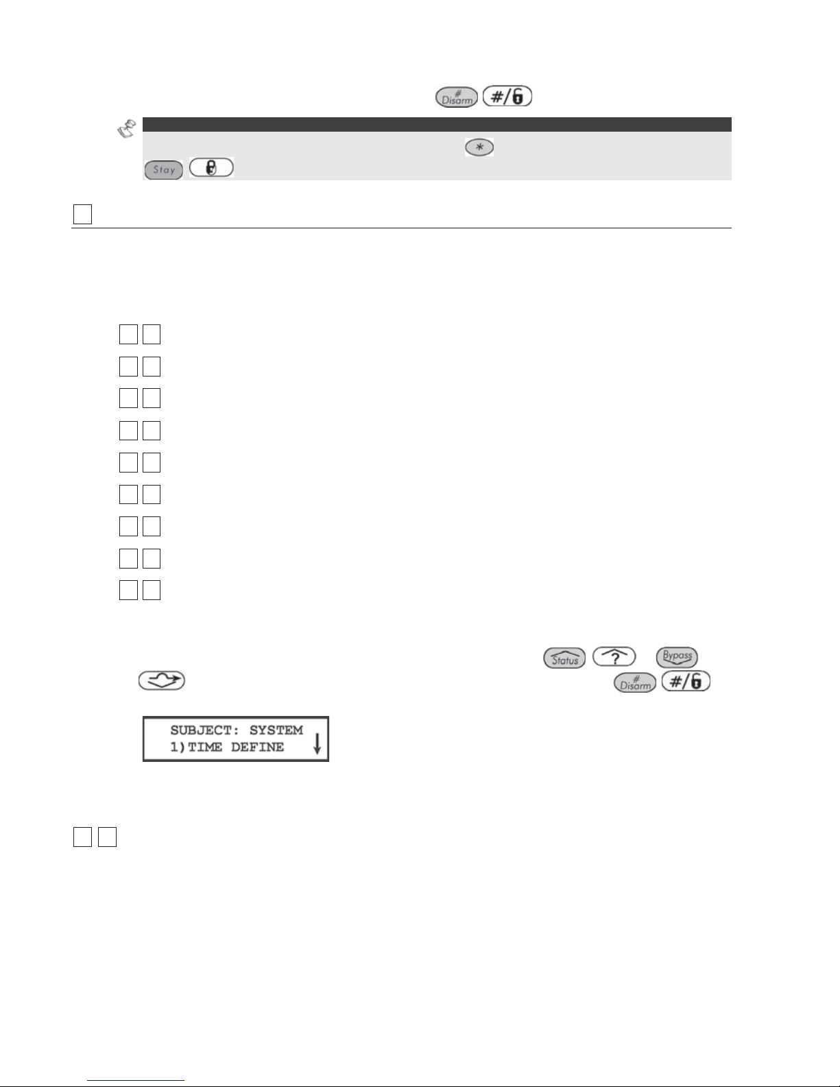
46 ProSYS Installation and Programming Manual
2 Press the Quick Keys listed in sequence (from left to right) to locate the option listed
in the Parameter column and then press
/
.
NOTE:
When programming items in sequence, you can use the key to exit to the previous level and the
/ key to toggle the options.
11
System
The System menu provides access to submenus and their related parameters that are used
for programming configuration settings applicable to the entire system.
After you access the System menu from the main Installer Programming menu, as described
in this section, you can access the following submenus:
11 11
Time Define, page 46
11 22
System Control, page 49
11 33
Set Clock, page 57
11 44
Windowing, page 57
11 55
System Labels, page 58
11 66
Tamper Sound, page 60
11 77
Default Enable/Disable, page 60
11 88
Service Information, page 61
11 99
System Version, page 61
To access the System menu:
From the Installer Programming menu, press [1], or press the
/
or
/
keys until you find the number [1] System option and then press
/
.
The first submenu (TIME DEFINE) appears:
You are now in the System menu and can access the required submenus, as described in
the following sections.
11 11
System: Time Define
The Time Define menu contains parameters that specify the duration of an action.
To access the Time Define menu:
1 Access the System menu, as described on page 46.
2 From the System menu, press [1] to access the Time Define menu options. The
following display appears:
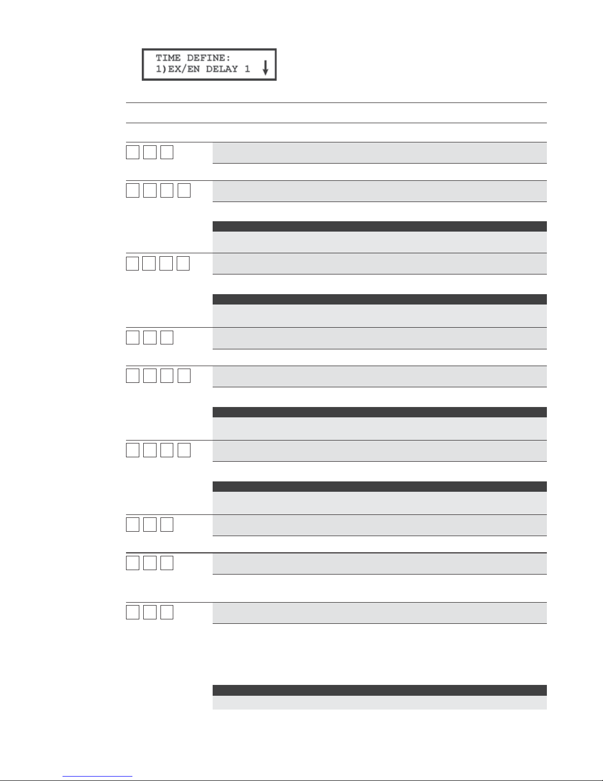
ProSYS Installation and Pr ogramming Manual 47
3 Access and configure the parameters in the Time Define menu, as follows:
System: Time Define
Quick Keys Parameter Default Range
11 11 11
Exit/Entry Delay 1
Exit/Entry Delays (Group 1).
11 11 11 11
Entry Delay 1
30 seconds 0-255 seconds
Duration of Group 1 Entry Delay.
Note:
For SIA CP 01 installations the range of entry time should be between 30 to 240
seconds with default of 30 seconds.
11
11 11 22
Exit Delay 1
45 seconds 0-255 seconds
Duration of Group 1 Exit Delay.
Note:
For SIA CP 01 installations the range of exit time should be between 45 to 255
seconds with default of 60 seconds.
11 11 22
Exit/Entry Delay 2
Exit/Entry Delays (Group 2).
11 11 22 11
Entry Delay 2
45 seconds 0-255 seconds
Duration of Group 2 Entry Delay.
Note:
For SIA CP 01 installations the range of entry time should be between 30 to 240
seconds with default of 30 seconds.
11 11 22 22
Exit Delay 2
60 seconds 0-255 seconds
Duration of Group 2 Exit Delay.
Note:
For SIA CP 01 installations the range of exit time should be between 45 to 255
seconds with default of 60 seconds.
11 11 33
Bell Timeout
04 minutes 01-90 minutes
Duration of the external siren(s) during alarm.
11 11 44
Bell Delay
00 minutes 00-90 min. /sec.
The time delay before the keypad siren and the external siren operates after
the onset of an alarm.
11 11 55
Switched Auxiliary Break
10 seconds 01-90 seconds
The time that the power supplied to the system's smoke detectors through the
Utility Output is interrupted during a user-initiated smoke detector reset,
typically performed after a Fire Alarm or automatically when a fire verification
is defined in the system control. (Refer to Do uble Verification of Fire Alarms,
page 50, for additional details.)
NOTE:
This feature is supported through any Utility Output that is defined as Switch AUX.

48 ProSYS Installation and Programming Manual
System: Time Define
Quick Keys Parameter Default Range
11 11 66
Wireless Module Times
Specifies the time intervals relating to the operation of the wireless module.
11 11 66 11
Jamming Time
NONE NONE, 10, 20 or
30 seconds
Specifies the period of time that the ProSYS's wireless module tolerates
unwanted radio frequencies capable of blocking (jamming) signals produced
by the system's transmitters. Once the specified time is reached, the Main
Panel sends a Report Code to the Monitoring Station (MS). (Refer to Jammin
g
Trouble, page 151.)
NONE: No jamming will be detected or reported.
NOTE:
Refer also to Audible Jamming, page 51. Different sounds will be produced when
j
amming is detected, depending on the defined Audible Jamming time.
11 11 66 22
Supervisory (S.V.) Time
0 hours 0-7 hours
Specifies how often the ProSYS checks for supervision signals, identifying
each of the system's transmitters. The Main Panel generates a local trouble
signal identifying the zone of any transmitter from which a signal is not
received during the specified interval. The Main Panel then sends the
Supervision Report Code to the MS. (Refer to Report Codes: Zones, pag e
140.)
NOTES:
0 hours disables supervision.
It is recommended to set the supervision time to a minimum of 3 hours.
11 11 77
Zone Test Times
Specifies the start time and interval between Zone Tests. These features
permit an automatic self-testing routine for up to 16 zones. (For further
information about this concept, refer to the procedures described in Zone Self-
Test, page 80.)
11 11 77 11
Start Test At
HR:00
MIN:00
00-24 hours
00-59 minutes
Use the Start Test At parameter to define the time of day that the test should
first be performed (defined in 24-hour format).
11 11 77 22
Zone Test Period
HR:00 00-24 hours
Use the Zone Test Period parameter to define how often, after the initial test,
each subsequent test will occur.
11 11 88
AC Off Delay Time
MIN: 30 0-255 minutes
In the case of a loss of AC power, this parameter specifies the delay period
before reporting the event or operating the Utility Output.
If the delay time is set to 0 (zero), there will be no delay period.
11 11 99
More
Additional options.
11 11 99 11
Phone Line Cut Delay Time
MIN: 04 00-20 minutes

ProSYS Installation and Pr ogramming Manual 49
System: Time Define
Quick Keys Parameter Default Range
In the case of a cut phone line, this parameter specifies the delay period
before reporting the event into the event log or operating the Utility Output.
00 indicates no supervision of the telephone line
11 11 99 22
Guard Delay
MIN: 30 01-99 minutes
Specifies the time period that the system will be disarmed after an authorized
user enters a Guard code.
11 22
System: System Control
The System Control menu contains parameters that control specific system operations.
To access the System Control menu:
1 Access the System menu, as described on page 46.
2 From the System menu, press [2] to access the System Control menu options. The
following display appears:
3 Access and configure the parameters in the System Control menu, as follows:
System: System Control
Quick Keys Parameter Default Range
11 22 0101
Quick Arm
YES YES/NO
Y
ES: Eliminates the need for a User Code when arming in STAY or AWAY
modes.
NO: A valid User Code is required for arming in STAY or AWAY modes.
11 22 0202
Quick UO
YES YES/NO
Y
ES: A user can activate a Utility Output without the need to enter a User
Code.
NO: A User Code is required to activate a Utility Output.
11 22 0303
Allow Bypass
YES YES/NO
Y
ES: Permits zone bypassing by authorized system users after entering a
valid User Code.
NO: Zone bypassing is NOT permitted.
11 22 0404
Quick Bypass
NO YES/NO
Y
ES: Eliminates the need for a valid User Code when bypassing zones.
NO: Qualified users must enter a valid User Code to bypass zones.
11 22 0505
False Code Trouble
NO YES/NO
Y
ES: A False Code report is sent to the MS after three successive attempts at
arming or disarming in which an incorrect User Code is entered. No alarm
sounds at the premises, but a trouble indication appears on the system's
keypad(s).
NO: A local alarm is sounded at the premises.

50 ProSYS Installation and Programming Manual
Quick Keys Parameter Default Range
11 22 0606
Bell Squawk
YES YES/NO
Y
ES: If a keyswitch or a rolling code remote control is used, a brief "chirp" is
produced from the system's external sounder(s) (at the conclusion of the Exit
Delay period), as follows:
♦ One chirp indicates the system is armed. (Also from keypad)
♦ Two chirps indicate the system is disarmed.
♦ Four chirps indicate the system is disarmed after an alarm.
NO: No "chirp" is produced.
11 22 0707
Bell 30/10
NO YES/NO
Y
ES: Any internal sounders cease to sound for 10 seconds after each 30
seconds of operation.
NO: Any internal sounders operate without interruption.
11 22 0808
Alarm Phone Cut
NO YES/NO
Y
ES: Activates the external sounders if the phone line is cut or the telephone
service is interrupted for the time defined in the Phone Line Cut Delay Time
parameter. (Refer to Phone Line Cut Delay Time, page 48.)
NO: No activation occurs.
11 22 0909
3 Minute Bypass
YES YES/NO
Y
ES: Bypasses all zones automatically for 3 minutes when power is restored
to an "unpowered" system to allow for the stabilization of motion and/or smoke
detectors.
NO: No bypassing occurs.
11 22 1010
Double Verification of
Fire Alarms
NO YES/NO
Y
ES: Implemented on detection of smoke or fire for verification. Power to the
smoke detector(s) in the affected zone is cut off and restored after the time
defined in Switched Auxiliary Break, page 47. If a subsequent detection
occurs in the same zone within 1 minute of the first detection, the system
emits a fire alarm.
NO: No fire alarm verification takes place.
NOTE:
This feature is supported through any Utility Output that is defined as Switch AUX.
11 22 1111
Audible Panic
NO YES/NO
Y
ES: Any internal sirens operate when a "Police Alarm" is initiated at the
keypad or when a Panic Zone is activated.
NO: No internal siren operation occurs during a keypad "Police Alarm,"
making the alarm truly "silent" (Silent Panic).
NOTE:
The system also transmits a Panic report to the MS.

ProSYS Installation and Pr ogramming Manual 51
11 22 1212
Buzzer-->Bell
NO YES/NO
Y
ES: If an alarm occurs when the system is armed in the STAY mode, each
keypad sounds for 15 seconds before the external sounders operate.
NO: An alarm in the STAY mode causes each keypad and any internal
sounders to operate simultaneously.
11 22 1313
Alarm ZE Cut
NO YES/NO
Y
ES: Produces an alarm if the communication between the Main Panel and
any expander is lost. A report is transmitted to the MS.
NO: No alarm occurs. The system, however, produces a local trouble
indication.
11 22 1414
Fire Temporal Pattern
NO YES/NO
Y
ES: During a fire alarm, the external sounders produce a pattern of three
short bursts, followed by a brief pause.
NO: During a fire alarm, the flow of sounds produced by the external sounder
is a pattern of 2 seconds ON, then 2 seconds OFF.
11 22 1515
Code Grand Master
NO YES/NO
Y
ES: Only a user with the Grand Master Authority Level can change all User
Codes, along with the TIME and DATE.
NO: Users with the Master and Manager Authority Levels can change their
own User Codes, all codes with a lower Authority Level, and the TIME and
DATE.
11 22 1616
Audible Jamming
NO YES/NO
Relates to the Jamming Time parameter, described on page 48.
Y
ES: Once the specified time is reached, the Main Panel activates any
internal sounders and sends a Report Code to the MS. (Refer to Jamming
Trouble, page 151.)
NO: Same as above, except the internal sounders do not operate.
11 22 1717
Technician Tamper
NO YES/NO
Y
ES: It is necessary to enter the Installer Code to reset a Tamper Alarm
(indicated by a lit keypad Tamper /
LED). Therefore, Tamper Alarm (and
Tamper /
LED) resets require the intervention of the MS. However, the
system can still be armed although the Tamper /
LED is on.
NO: A Tamper Alarm (and the resulting Tamper /
LED) is reset by
correcting the problem, requiring no
MS help.
11 22 1818
Technician Reset
NO YES/NO
Y
ES: It is necessary to enter the Installer Code to reset an alarmed partition
after it's been disarmed. This requires the intervention of the
MS.
NOT E:
Before the READY/ LED can light, all zones within the partition must be
secured.
NO: Once an alarmed partition is reset, the READY / LED lights when all
zones are secured.

52 ProSYS Installation and Programming Manual
11 22 1919
Abort Alarm
NO YES/NO
Y
ES: If an alarm is sent in error, it is possible for the MS to receive an Abort
Alarm Code, sent subsequent to the initial Alarm Code. This happens if a valid
User Code is entered to reset the alarm within 90 seconds of initiation.
NO: No Abort Alarm Code can be sent once an alarm has been triggered.
Quick Keys Parameter Default Range
11 22 2020
Summer/Winter Clock
NO YES/NO
Y
ES: The ProSYS automatically sets its Time of Day clock one hour ahead in
the spring (on the last Sunday in March) and one hour back in the Autumn (on
the last Sunday in October).
NO: No automatic time accommodation is made.
11 22 2121
Forced Keyswitch Arming
YES YES/NO
Y
ES: Keyswitch or Proximity Key arming is performed on any partition. Any
violated (not READY) zone(s) in the partition will be bypassed automatically.
The partition is then "force armed," and all intact zones are capable of
producing an alarm.
NO: The partition cannot be armed using a keyswitch or Proximity Key until all
violated (not READY) zones are secured.
11 22 2222
Pager
NO YES/NO
Relates to the use of an alphanumeric pocket pager with the option to notify
the customer when an event occurs. The pager's phone number must be
programmed as a Follow-Me device in the ProSYS's User Functions.
Y
ES: When a call is made, event information is displayed on the
alphanumeric pager.
The following examples and tips clarify the YES option.
1. Enter the phone number, as described in the ProSYS User's Manual, by
entering the letter [B] (which instructs the dialer to wait a fixed period of
time before continuing).
2. Add the partition number to which the Follow-Me relates.
3. The following messages are delivered automatically to the pager.
Displayed
eaning
1# The system (or partition) is armed.
2#
he system (or partition) is disarmed.
3#
he system (or partition) is in ALARM mode.
In the example below, the first column displays the characters that are added
after you enter the letter [B]:
Characters Added
After [B]
If Displayed Meaning
1 11# Partition 1 is armed.
2 21# Partition 2 is armed.
3 32# Partition 3 is disarmed.
8 83# Partition 8 is in ALARM mode.
NO: The ProSYS calls a pager during an alarm situation only in the partition
for which it is programmed as a Follow-Me device. There are no
enhancements to the standard message.

ProSYS Installation and Pr ogramming Manual 53
11 22 2323
Arm Pre-Warning
YES YES/NO
Related to auto arm/disarm operation.
Y
ES: For any partition(s) set up for Auto Arming, an audible Exit Delay
(warning) countdown will commence 4.25 minutes prior to the automatic
arming. (Refer to the user's Daily Arm function in the ProSYS User's Manual
for additional details.)
During this period, Exit Delay beeps will be heard in the keypads assigned to
these partitions.
You can enter a valid User Code at any time during the countdown to delay
the partition's automatic arming by 45 minutes.
When an "auto-armed" partition is disarmed, as described above, it can no
longer be automatically armed during the current day.
The extended 4.25 minutes warning does not apply to automatic STAY mode
arming.
NO: Auto Arming for any programmed partition(s) takes place at the
designated time.
The programmed Exit Delay period and any audible signal occur as expected.
11 22 2424
Low Battery Arm
YES YES/NO
Y
ES: Allows arming of the system when a low battery condition is detected
(also in the Power Supply expansion module).
NO: Does not allow arming of the system when a low battery condition is
detected.
11 22 2525
Engi neer Tamper
NO YES/NO
Y
ES: After a Tamper alarm, the system is not ready to arm and the TAMPER
/
LED is not restored. This requires the intervention of the MS.
NO: After a Tamper alarm is restored, the system is ready.
11 22 2626
Blank Display
NO YES/NO
Y
ES: One minute after the last keypad operation, the display will appear
blank. After pressing any key, an E nter Code message will be displayed.
After the code is entered, the display returns to the normal operation mode.
Select this option for keypads that can be viewed from outside the protected
area to disguise the system status.
NO: The keypad display operates normally.
11 22 2727
24 Hour Bypass
NO YES/NO
Y
ES: It is possible for the user to bypass a 24-hour zone.
NO: It is not possible for the user to bypass a 24-hour zone.

54 ProSYS Installation and Programming Manual
11 22 2828
IMQ Install
NO YES/NO
Y
ES: Causes the following parameters to function as follows:
Auto Arm Bypass: If there is an open zone during the Auto Arm process,
the system will be armed, and an alarm will be sounded (unless the
open zone is closed).
Guard User: If a Guard user disarms a partition, the system will be armed
automatically after the predefined time period (refer to Guard, page
49). If there is an open zone during the arming process, the system
will be armed, and an alarm will be sounded (unless the open zone is
closed).
NO: Causes the following parameters to function as follows:
Auto Arm Bypass: If the Auto Arm programming arms the system and
there is an open zone during the auto arm, the system will bypass the
open zones and arm the system.
Guard User: If a Guard user disarms a partition, the system will be armed
automatically after the predefined time period (refer to Guard, page
49). If there is an open zone during the arming process, the partition
will be bypassed.
11 22 2929
Grand Master
Authority/Partition
YES YES/NO
Y
ES: Specifies that the allowed partitions and the authority level of a user can
be changed by the Installer (Installer menu) or the Grand Master (User menu).
NO: Specifies that only the Installer can change the partition and the authority
level of a user from the Installer programming menu.
11 22 3030
Double Code
NO YES/NO
Requires two User Codes or proximity cards to be entered in order to disarm
the system, which provides a higher level of security. In addition, only the
common partitions between the two users will be disarmed.
Y
ES: To disarm the system, two users must enter their codes or pass their
proximity cards one after the other. The time between entering the two User
Codes is 60 seconds. If the second code is entered after 60 seconds, 3 error
beeps will be sounded.
NO: Enables any user, with the appropriate authority, to disarm the system
using only one User Code or pro ximity card.
NOTES:
When using the Double Code feature, there will not be a restriction in operating
w
ith one user through the Electronic Key or Access Control module.
The Maid, Arm Only, UO O nly, and Guard authority levels cannot be used to
perform double code disarming.

ProSYS Installation and Pr ogramming Manual 55
11 22 3131
Disarm Stop FM
YES YES/NO
Y
ES: The Follow-Me calls will stop when the partitions are disarmed by a
User Code or proximity card.
NOTES:
When a latched keyswitch is activated, you can only disarm the system by
releasing the latched keyswitch.
When the Advanced Digital Voice module is connected to the system, the Disarm
Stop FM feature acts as NO even if it is defined as YES.
NO: The Follow-Me calls will continue to be made when the partitions are
disarmed by a User Code or proximity card.
11 22 3232
Global Follower
YES YES/NO
Y
ES: Specifies that all zones (that are programmed to follow an Exit/Entry
Delay time) will follow the Exit/Entry Delay time of any armed partition.
NO: Specifies that all zones (that are programmed to follow an Entry Delay
time) will follow the Entry Delay time of only the partitions to which they are
assigned.
11 22 3333
Area
NO YES/NO
Changes the system operation to Area instead of Partition, which then
changes only the operation of the common zone.
Y
ES: When selected, the following points are releva nt:
The common zone will be armed after any partition is armed.
The common zone will be disarmed only when all partitions are disarmed.
NO: When selected, the following points are relevant:
The common zone will be armed only when all partitions are armed.
The common zone will be disarmed when any partition is disarmed.
11 22 3434
Disable Keypad When Auto
Disarm Exists
NO YES/NO
Y
ES: When a partition is armed manually or in AUTO ARM mode, and an
Auto Disarm time is defined, this parameter specifies that all the keypads that
are masked to this partition will not function and that it will be impossible to
disarm the relevant partition.
NOTE:
The partition can be disarmed only by using the Upload/Download software or the
Auto Disarm function.
NO: When a partition is armed manually or in AUTO ARM mode, and an Auto
Disarm time is defined, the relevant keypads will function normally.
11 22
3535
Audible Proximity Tamper
NO YES/NO
This parameter relates to the BUS siren.
Y
ES: A proximity anti approach violation will activate the siren.
NO: A proximity anti approach violation will not activate the siren and will be
regarded as trouble by the system.
11 22
3636
Anti Mask = Tamper
NO YES/NO
Used to determine the operation of Anti Masking detection in a BUS zone.
Y
ES: Anti mask violation will activate tamper alarm.
NO: Anti mask violation will be regarded as trouble event.

56 ProSYS Installation and Programming Manual
11 22
3737
Prox AM=Tamper
NO YES/NO
Used to determine the operation of the proximity anti masking detection
indicated by the MW channel in the WatchOUT DT detector.
Y
ES: Proximity anti mask detection will activate the tamper alarm.
NO: Proximity anti mask detection will be regarded as a trouble event.
Note that Proximity AM operates for approximately 2.2 seconds when the
detector is approached in close proximity.
Ensure that Prox Anti Mask has been enabled when configuring the
WatchOUT DT BUS zone parameters ([2][0][3][zz][8]).
11 22
3838
Siren Auxiliary = Tamper
NO YES/NO
This parameter relates to the BUS siren.
Y
ES: A siren auxiliary trouble will be regarded as tamper alarm by the system.
NO: A siren auxiliary trouble will be regarded as trouble by the system.
11 22
3939
GSM Pre Alarm Indication
NO YES/NO
Related to the GSM/GPRS module. This parameter specifies if the ProSYS
w
ill send a pre alarm message to the GSM when an entry delay starts.
Y
ES: The ProSYS will send the GSM a pre alarm signal at the beginning of
the entry delay. If the GSM does not receive a cancellation signal from the
ProSYS at the end of the entry time, it will send a burglar message report to
the MS.
NO: No pre alarm indication is initiated to the GSM.
11 22
4040
Disable GSM Battery
NO YES/NO
This parameter indicates if there will be a fault indication when no backup
battery is connected to the GSM/GPRS module.
NO: The GSM low battery indication is enabled. Use this option when the
GSM is installed in its own casing and its backup battery is connected.
Y
ES: GSM low battery indication will be disabled. Use this option when the
GSM module in installed inside the casing of the ProSYS. No battery is
connected to the GSM battery connectors.

ProSYS Installation and Pr ogramming Manual 57
System: Set Clock
The Set Clock menu enables you to set the system's date and time.
To access the Set Clock menu:
1 Access the System menu, as described on page 46.
2 From the System menu, press [3] to access the Set Clock menu options. The following
display appears:
3 Access and configure the parameters in the Set Clock menu, as follows:
System: Set Clock
Quick Keys Parameter Default Range
11 33 11
System Date
JAN 01 2000 (SAT) MM DD YYYY (DAY)
Sets the current DATE. (Refer to Chapter 4, Programming the ProSYS, for
instructions for using the keypad.)
11 33 22
System Time
00:00 HH:MM
Sets the current TIME (in 24-hour format).
11 44
System: Windowing
The Windowing menu enables you to define a time window and its effective days for
Reporting of Opening/Closing signals when the system is either disarmed or armed outside of
the specified time window.
To access the Windowing menu:
1 Access the System menu, as described on page 46.
2 From the System menu, press [4] to access the Windowing menu options. The
following display appears:
3 Access and configure the parameters in the Windowing menu, as follows:
System: Windowing
Quick Keys Parameter Default Range
11 44 11
Window Start
HR:00
MIN:00
00-24 hours
00-59 minutes
Sets the window's START time (in 24-hour format).
11 44 22
Window Stop
HR:00
MIN:00
00-24 hours
00-59 minutes
Sets the window's STOP time (in 24-hour format).
11 44 33
Window Days
All
Sunday (Y/N) through
Saturday (Y/N)

58 ProSYS Installation and Programming Manual
System: Windowing
Quick Keys Parameter Default Range
Sets the days of the week in which the window is activated.
Use the
/
or / keys to select the days of the
w
eek.
Use the
/ key to toggle between Y and N to define if the window
is active for the given day.
The window and the days chosen here also apply to the automatic arming and
disarming of the system. (Refer to the ProSYS User's Manual for additional
details.)
11 55
System: System Labels
The System Labels menu enables you to modify the labels displayed by the LCD keypad that
identify the system and partition labels.
Entering a New Label Using the LCD Keypad
You can rename the labels that identify zones and partitions by changing the default labels
(Partition 1, Partition 2, and so on) to, for example, The Jones's, Sales Dept, or Mastr
Bedr as appropriate.
To enter a new label:
Use the keys on the keypad to produce characters according to the table below. Pressing a
particular key, toggles between the characters available from that key in the sequence listed
below followed by a blank space. The ProSYS permits a total of 74 characters (letters,
numbers, and symbols) for use in labeling.
NOTE:
The data sequence of each key in the following table is suitable only for the English version.
KEY DATA SEQUENCE
1
1 A B C D E F G H I J K L M
2
2 N O P Q R S T U V W X Y Z
3
3 ! '' & ' : – . ? / ( )
4
4 a b c d e f g h i j K l m
5
5 n o p q r s t u v w X y z
6 - 0
Each of these keys toggles between producing their number and a blank space.
/
Use this button to toggle forward through the available characters.
/
Use this button to toggle backward through the available characters.
/
/
To move the cursor to the left, press the UP arrow button (STAT).
To move the cursor to the right, press the DOWN arrow button (BYP).

ProSYS Installation and Pr ogramming Manual 59
/
To enter a completed label into the system, press Enter.
The number of allowed characters for each type of label varies, as follows:
♦ Zone Label: Up to 15 characters
♦ Partition Label: Up to 12 characters
♦ Programmable Output Label: Up to 12 characters
♦ Message to the User Label: Up to 12 characters
♦ Service Information Label: Up to 16 characters
♦ Service Name Label: Up to 16 characters
♦ System Global Label: Up to 16 characters
♦ User Label: Up to 10 characters
To access the System Labels menu:
1 Access the System menu, as described on page 46.
2 From the System menu, press [5] to access the System Labels menu options. The
following display appears:
3 Access and configure the parameters in the System Labels menu, as follows:
System: System Labels
Quick Keys Parameter Default Range
11 55 00
Global
Security System Any 16 characters
Edits the global (system) label for viewing during Download sessions.
11 55 1 to 81 to 8
Partitions 1 through 8
Partitions 1
through 8
Any 12 characters
Partitions 1 through 8.
Example: The example below describes how to edit each partition label.
TO ASSIGN THE JONES'S NAME TO PARTITION 1, FOLLOW THE STEPS
BELOW:
Press [1] for partition 1 and press
/
.
1. Press the [2] key repeatedly until a T appears in the display; press the
/
key once to move the cursor to the right.
2. Press the [4] key repeatedly until an h appears in the display; again, press
the
/ key to advance the cursor.
3. Press the [4] key repeatedly until an e appears and press the
/
key to advance the cursor.
4. Press the [6], [7], [8], [9], or [0] key to create a space and press the
/
key to advance the cursor.
5. Press the [1] key until a J appears.
6. Use the elements of this procedure to assign the remaining Partition Labels
as described in Entering a New Label Using the LCD Keypad, page 58.
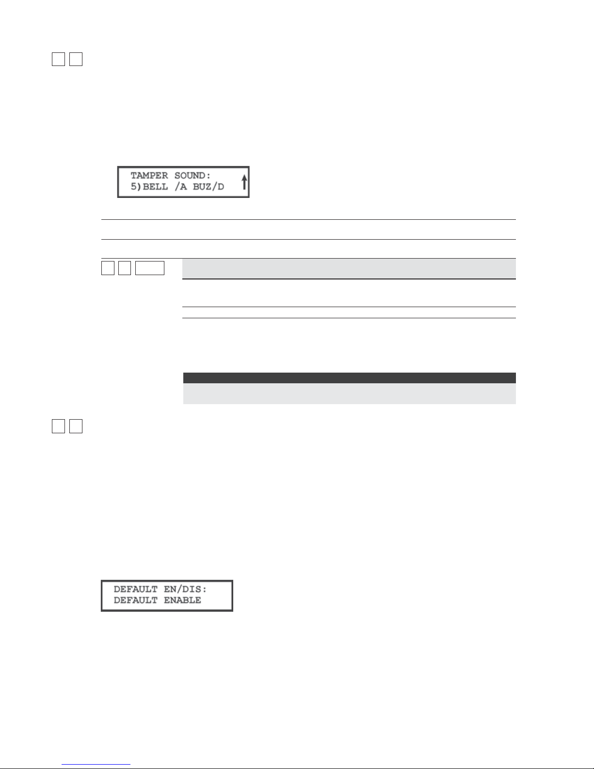
60 ProSYS Installation and Programming Manual
11 66
System: Tamper Sound
The Tamper Sound menu contains parameters that enable you to set the sound(s) that will be
produced by the ProSYS after a Tamper violation of a keypad and/or an expansion module.
To access the Tamper Sound menu:
1 Access the System menu, as described on page 46.
2 From the System menu, press [6] to access the Tamper Sound menu options. The
following display appears:
3 Access and configure the parameters in the Tamper Sound menu, as follows:
System: Tamper Sound
Quick Keys Parameter Default Range
11 66 1 to 51 to 5
TAMPER SOUND
BELL/A BUZZER/D 1 to 5
Sets the sound(s) produced by a Tamper violation of a keypad and/or an
expansion module, as follows:
e
y
ound
ilent
Bell (External Siren) Only
Buzzer (Keypad Piezo) Only
Bell + Buzzer
Bell/A Buzzer/D
NOTE:
If you select the last option (5), during a Tamper alarm, a bell will sound when the
system is armed, and a buzzer will sound when the system is disarmed.
11 77
System: Default Enable/Disable
Default: Enable
Range: Enable/Disable
The Default Enable/Disable menu contains parameters that relate to what happens if the
Main Panel's DEFAULT (J2) Jumper is in place when power to the Main Panel is switched off
and then on.
To access the Default Enable/Disable menu:
1 Access the System menu, as described on page 46.
2 From the System menu, press [7] to access the Default Enable/Disable menu options.
The following display appears:
3 Select the required option, as follows:
O ENABLE: The Main Panel loses its programmed configuration, including all Labels and
User/Installer Codes. It returns to its original, factory default configuration. It can then
be reprogrammed by any user who knows the default User and Installer Codes.
O DISABLE: The system cannot be returned to the manufacturer's default settings by an
unauthorized user. The Main Panel maintains its previously programmed configuration,

ProSYS Installation and Pr ogramming Manual 61
keeping all Parameters, Labels, and User/Installer Codes intact. As with any instance
of a total loss of power, you must reset the system's TIME and DATE.
11 88
System: Service Information
The Service Information menu supplies servicing information accessible to the system's
users.
To access the Service Information menu:
1 Access the System menu, as described on page 46.
2 From the System menu, press [8] to access the Service Information menu options. The
following display appears:
3 Access and configure the parameters in the Service Information menu, as follows:
System: Service Information
Quick Keys Parameter Default Range
11 88 11
Service Name
Any 16 characters
Enables you to insert and/or edit the name of the MS from whom service may
be obtained. For additional details about how to enter a label, refer to Entering
a New Label Using the LCD Keypad, page 58.
11 88 22
Service P ho ne
Any 16 characters
Enables you to insert and/or edit the service phone number.
11 99
System: System Version
The System Version menu supplies the current system version information.
To access the System Version menu:
1 Access the System menu, as described on page 46.
2 From the System menu, press [9] to access the System Version menu option. The
system version with the software's checksum number is displayed.

62 ProSYS Installation and Programming Manual
22
Zones
The Zones menu provides access to submenus and their related parameters that are used for
programming the characteristics of each of the system's protected zones.
You can program by zone or by category. The first submenu allows you to program all
parameters for each zone one by one. You can also program one or more zones by category
using the following sub-menus: Partitions/Groups, Zone Type, Zone Sound, Termination,
Loop Response, Cross Zone, and Labels.
After you access the Zones menu from the main Installer Programming menu, as described in
this section, you can access the following submenus:
22 11
One By One, page 62
22 22
Partitions/Groups, page 64
22 33
Zone Type, page 65
22 44
Zone Sound, page 70
22 55
Termination, page 71
22 66
Loop Response, page 73
22 77
Cross Zones, page 74
22 88
Labels, page 75
22 99
Maintenance, page 76
22 00
Miscellaneous, page 84
To access the Zones menu:
From the main Installer Programming menu, press [2], or press the / or /
keys until you find the number [2] Zones option and then press / .
The first submenu (ONE BY ONE) appears:
You are now in the Zones menu and can access the required submenus, as described in
the following sections.
22 11
Zones: One by One
The One by One menu contains parameters that enable you to program each of the following:
Zone Partitions
Zone Group
Zone Type
Zone Sound
Zone Termination
Zone Loop Response
Zone Label
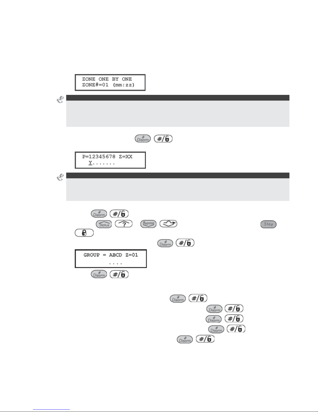
ProSYS Installation and Pr ogramming Manual 63
The following procedure describes how to program the full complement of parameters for
each zone on a one-by-one basis.
To access the One by One menu:
1 Access the Zones menu, as described on page 62.
2 From the Zones menu, press [1] to access the One by One menu options. The
following display appears:
NOTES:
In the mm:zz designation, the mm = the module ID number, and the zz = the zone number for this
module (the number next to the terminal block on the expander).
In the ProSYS 128, the zone numbers are represented by three digits (zzz). For example, Zone 1 will
be 001.
3 Specify a two-digit zone number from which you want to start programming (for
example, 01) and press
/ again to access the category on Partition
Assignments. The following display appears:
NOTES:
The XX in the Z=XX designation is for the zone number.
In a multi-partition system, a zone can be assigned to more than one partition.
A system without partitions is regarded as having a single partition (meaning Partitio n 1).
4 Use keys [1] to [8] to toggle the partition status between
[Y] YES and [N] NO.
5 Press
/ to proceed to Zone Groups.
6 Use the
/ or / keys to select the group, use the /
key or the A/B/C/D keys to toggle between [Y] YES and [N] NO in the
following display, and then press
/
:
7 Press
/ to proceed to Zone Types.
8 To program Zone Types, as well as the other four zone categories, select the following
options (refer to the following pages for further instructions):
O Zone Type: Select a type and press
/ .
O Zone Sound: Select a sounding method and press
/
.
O Zone Termination: Select a termination and press
/ .
O Loop Response: Select a loop response and press
/
.
O Zone Labels: Assign a label and press
/ .

64 ProSYS Installation and Programming Manual
IMPORTANT:
When using the One by One method, the listing of each zone's parameters is sequential.
Once Zone 1's parameters have been programmed, they are followed by Zone 2's, then
Zone 3's, and so forth.
To program one or more of the system's zones using the One by One method, changes
made to any (or all) of the Zone parameters will NOT be recorded without going through
the One by One list, ending with the Zone Labels parameter of the last zone you want to
program.
After making changes to the Zone Labels parameter, press
/
. This produces a
one-second tone and assures that change(s) you make to the zone programming are
recorded when you exit the One by One programming mode.
As mentioned before, you can select a single parameter and program (or review) it for each
of the system's zones, as follows:
[2] Partitions/Groups, below
[3] Zone Type, page 65
[4] Zone Sound, page 70
[5] Termination, page 71
[6] Loop Response, page 73
[8] Zone Labels page 75
22 22
Zones: Partitions
Default: All zones are assigned to Partition X
Range: Partitions 1 to 8
The Partitions menu contains parameters that enable you to program the partition assignment
for each zone.
To access the Partitions menu:
1 Access the Zones menu, as described on page 62.
2 From the Zones menu, press [2] to access the Partitions menu options. The following
display appears:
3 Specify a two-digit zone number and press
/ . The following display
appears:
NOTE S:
The XX in the Z=XX designation refers the zone number.
In a multi-partitioned system, a zone can be assigned to more than one partition.
A system without partitions is regarded as having a single partition (meaning Partition 1).
4 Use keys [1] to [8] to toggle the partition status between [Y] YES or [N] NO.
5 Press
/ . The following display appears:

ProSYS Installation and Pr ogramming Manual 65
6 Use the
/ or / keys to select the group and use the /
key to toggle between
[Y] YES and [N] NO.
NOTE:
Each partition has 4 groups. The zone group definition is common to each of the partitions assigned to
the zone.
22 33
Zones: Zone Type
The Zone Type menu contains parameters that enable you to program the zone type for any
zone. Setting the zone type is partly determined by the arming levels. Three arming levels
exist, as follows:
Disarm: The system reacts only to those zones defined as 24 HR, Fire, Panic, and Trouble.
Arm: The system reacts to all zones.
Stay: The system does not react to zones defined as internal (home). This setting allows
freedom of movement in those zones.
There are 23 zone types in the system, as described in the following procedure.
To access the Zone Type menu:
1 Access the Zones menu, as described on page 62.
2 From the Zones menu, press [3] to access the Zone Type menu options. The following
display appears:
3 Specify a two-digit zone number and press
/
.
4 Access and configure the parameters in the Zone Type menu, as follows:
Zones: Zone Type
Quick Keys Parameter Default Arming Level/Range
22 33 ZZZZ
+
/
0000
Not Used
NONE
Disables a zone. All unused zones should be given this designation.
22 33 ZZZZ
+
/
0101
Exit/Entry 1
Arm/Stay
Used for Exit/Entry doors.
Zones in the Exit/Entry path, that when violated do not cause an intrusion
alarm during the Exit/Entry Delay periods (refer to Exit/Entry Delay 1 and
Exit/Entry Delay 2, page 47).
A zone must be secured during arming and when the delay expires. Use this
zone to trigger the entry delay.
22 33 ZZZZ
+
/
0202
Exit/Entry 2
ARM/STAY
Same as above, except that the Exit/Entry 2 time period applies.

66 ProSYS Installation and Programming Manual
Zones: Zone Type
Quick Keys Parameter Default Arming Level/Range
22 33 ZZZZ
+
/
0303
Exit (OP)/Entry
Default for zone 1 ARM/STAY
Used for an exit/entry door, open during the armed period.
This zone behaves as described in the Exit/Entry 1 parameter, shown above,
except that, if faulted when the system is being armed, it does NOT prevent
arming.
To avoid an intrusion alarm, it must be secured before the expiration of the
Exit Delay period.
22 33 ZZZZ
+
/
0404
Entry Follower
Default for zone 2 ARM/STAY
Usually assigned to motion detectors and to interior doors protecting the area
between the entry door and the keypad.
This zone(s) causes an immediate intrusion alarm when violated unless an
Exit/Entry zone was violated first. In this case, Entry Follower zone(s) will
remain bypassed until the end of the Entry Delay period.
22 33 ZZZZ
+
/
0505
Instant
Default for all zones
except 1 and 2
ARM/STAY
Usually intended for non-exit/entry doors, window protection, shock detection,
and motion detectors.
Causes an immediate intrusion alarm if violated after the system is armed or
during the Exit Delay time period.
When Auto Arm and Pre-
Warning are defined, the instant zone will be armed at
the end of the Pre-Warning time period.
22 33 ZZZZ
+
/
0606
I+Exit/Entry 1
(Interior+Exit/Entry 1)
Arm
Used for Exit/Entry doors, as follows:
If the system is armed in the AWAY (ARM) mode, the zone(s) provide a delay
(specified by Exit/Entry 1) allowing entry into and exit from an armed
premises.
If the system is armed in the STAY mode, the zone is bypassed.
IMPORTANT:
For gr eater security when armi ng in the STAY mode, it is possible to elimi nate the Entry
Delay period associated with any zone(s), classified as Exit/Entry Delay 1 by pressing the
/ key twice, one after another. In effect, this makes it an INSTANT zone
during the STAY mode of operation.
22 33 ZZZZ
+
/
0707
I+Exit/Entry 2
(Interior+Exit/Entry 2)
Arm
Same as the I+Exit/Entry 1 parameter, described above, but the Exit/Entry 2
time period is applicable.

ProSYS Installation and Pr ogramming Manual 67
Zones: Zone Type
Quick Keys Parameter Default Arming Level/Range
22 33 ZZZZ
+
/
0808
I+Exit(OP)/Entry
(Interior+Exit(OP)/Entry)
Arm
Used for an exit/entry door that, for convenience, may be kept open when the
system is being armed, as follows:
In AWAY (ARMED) mode, refer to the explanation in Zone Type 03,
page 66.
In STAY (ARMED) mode, the zone will be bypassed.
22 33 ZZZZ
+
/
0909
I+Entry Follow
(Interior+Entry Follower)
Arm
Generally used for motion detectors and/or interior doors (for example, foyer),
w
hich would have to be violated after entry in order to disarm the system, as
follows:
In AWAY (ARM) mode, refer to the explanation in Zone Type 04, page 66.
In STAY (ARM) mode, the zone will be bypassed.
22 33 ZZZZ
+
/
1010
I+Instant (Interior+Instant)
Arm
Usually intended for non-e xit/entry doors, window protection, shock detection
and motion detectors.
In AWAY (ARM) mode, a violation of this zone after the system is armed or
during the Exit Delay time period causes an immediate intrusion alarm.
In STAY (ARM) mode, the zone is bypassed.
22 33 ZZZZ
+
/
1111
UO Trigger
Arm
For a device or zone, which if violated at any time triggers a previously
programmed Utility Output, capable of activating an external indicator, relay,
appliance, and so on.
22 33 ZZZZ
+
/
1212
Day Zone
Arm
Usually assigned to an infrequently used door, such as an emergency door or
a movable skylight. Used to alert the system user if a violation occurs during
the disarmed period (trouble by day; burglary at night), as follows:
With the system armed (either AWAY or STAY), the zone acts as an instant
zone. A violation of this zone after the system is armed or during the Exit
Delay time period causes an immediate intrusion alarm.
With the system disarmed, a violation of this zone attempts to alert the user by
causing the POWER
/ LEDs on all keypads to flash rapidly. This directs
the user to view the system's TROUBLE indications.
Optionally, such a violation can be reported to the MS as a Zone Trouble.
(Refer to Report Codes: Miscellaneous, page 148.)
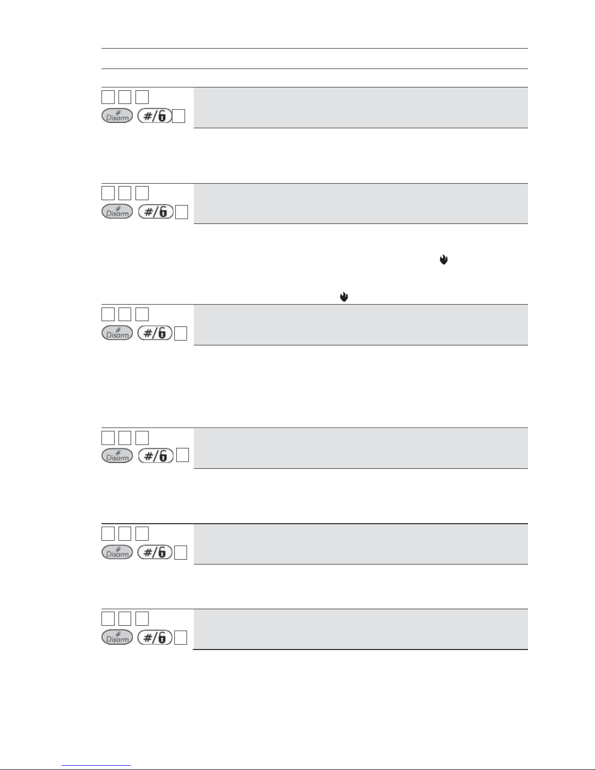
68 ProSYS Installation and Programming Manual
Zones: Zone Type
Quick Keys Parameter Default Arming Level/Range
22 33 ZZZZ
+
/
1313
24 Hours
All
Usually assigned to protect non-movable glass, fixed skylights, and cabinets
(possibly) for shock detection systems.
A violation of such a zone causes an instant intrusion alarm, regardless of the
syste m' s st ate.
22 33 ZZZZ
+
/
1414
Fire
All
For smoke or other types of fire detectors. This option can also be used for
manually triggered panic buttons or pull stations (if permitted), as follows:
If violated, it causes an immediate fire alarm, and the Fire
/ LED is lit
(steady).
A fault in the wiring to any fire zone causes a Fire Trouble signal (a rapid
flashing of the keypads' FIRE
/ LED).
22 33 ZZZZ
+
/
1515
Panic
All
Used for external panic buttons and wireless panic transmitters.
If violated, an immediate panic alarm is sounded (if the zone sound is not
defined as silent), regardless of the system's state. An alarm display will not
appear on the keypads.
If violated, an immediate panic alarm is sounded, regardless of the system's
state.
22 33 ZZZZ
+
/
1616
Special
All
For external auxiliary emergency alert buttons and wireless auxiliary
emergency transmitters.
If violated, an immediate auxiliary emergency alarm is sounded, regardless of
the system's state.
22 33 ZZZZ
+
/
1717
Pulse Keyswitch
Used to arm/disarm the system.
Connect an external momentary action keyswitch to any zone terminals given
this designation.
22 33 ZZZZ
+
/
1818
Exit Termination
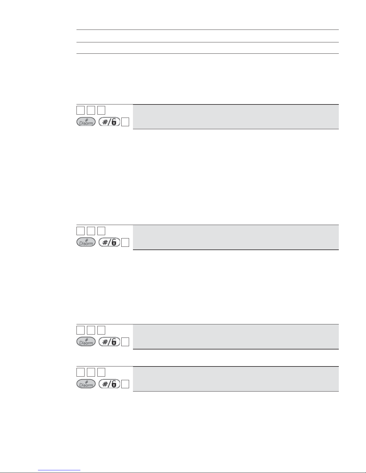
ProSYS Installation and Pr ogramming Manual 69
Zones: Zone Type
Quick Keys Parameter Default Arming Level/Range
This type of zone is used to avoid a false alarm by acting like an Exit
(OP)/Entry zone (see Exit (OP)/Entry, page 66).
When triggered (after arming the system and closing the door or opening the
door, arming the system, and closing the door), the system's Exit Delay time
period will be shortened to 3 seconds.
When you re-open the door, the entry time restarts.
22 33 ZZZZ
+
/
1919
Latch Keyswitch
Connect an external SPST latched (non-momentary) keyswitch to any zone
terminals given this designation and operate the keyswitch, as follows:
After arming one or more partitions using the keyswitch and then disarming
using the keypad, the related partitions will be disarmed. In order to arm
the partition using the keyswitch again, turn the key to the disarm position
and then to the arm position.
If a keyswitch latch is assigned to more than one partition and one of the
partitions is armed by using the keypad (the keyswitch stays in the disarm
position), then:
When changing the position of the keyswitch to the arm position, all the
disarmed partitions, which belong to this keyswitch, will be armed.
When turning the keyswitch to the disarm position, all the partitions will
be disarmed.
22 33 ZZZZ
+
/
2020
Entry Follower + Stay
All
Assigned to motion detectors and to interior doors protecting the area between
the entry door and the keypad, as follows:
In STAY (ARM) mode, a zone(s) given this designation behaves like an
Exit/Entry zone and is subject to the Entry and Exit Delay time periods
specified under Exit/Entry Delay 1. (Refer to Exit/Entry Delay 1, page 47.)
In AWAY (ARM) mode, a zone(s) given this designation behaves like an Entry
Follower Zone and causes an immediate intrusion alarm when violated
unless an Exit/Entry zone was violated first.
If so, an Entry Follower + Stay zone(s) remains bypassed until the end of the
Entry Delay period.
22 33 ZZZZ
+
/
2121
Keyswitch Delay
Used to apply the Exit/Entry Delay 1 parameter to the momentary keyswitch
operation. (Refer to Keyswitch, page 68.)
22 33 ZZZZ
+
/
2222
Latch KSW Delay
Used to apply the Exit/Entry Delay 1 parameter to the latched keyswitch
operation. (Refer to Latch Keyswitch, page 69.)

70 ProSYS Installation and Programming Manual
22 44
Zones: Zone Sound
The Zone Sound menu contains parameters that enable you to program the sound produced
when a system zone triggers an alarm. Reports to the MS are not affected by any of the
options in this menu.
To access the Zone Sound menu:
1 Access the Zones menu, as described on page 62.
2 From the Zones menu, press [4] to access the Zone Sound menu options. The following
display appears:
3 Specify a two-digit zone number and press
/ .
4 Access and configure the parameters in the Zone Sound menu, as follows:
Zones: Zone Sound
Quick Keys Parameter Default
22 44 ZZZZ
+
/
11
Silent
Produces no sound.
22 44 ZZZZ
+
/
22
Bell Only
Activates the bell sounders for the duration of the Bell Timeout period, or
until a User Code is entered, followed by use of the
/ key.
22 44 ZZZZ
+
/
33
Buzzer Only
Activates each keypad's internal piezo buzzer.
22 44 ZZZZ
+
/
44
Bell + Buzzer
Default for all zones
Activates the bell sounders and the keypads' buzzers simultaneously.
22 44 ZZZZ
+
/
55
Door Chime
The Door Chime parameter is used as an audible sounder to indicate the
violation of a zone(s), as follows:
If the system is DISARMED, the system's keypad buzzers make three
momentary sounds whenever the zone is violated.
If the system is ARMED, only the bell sounders will produce the alarm.

ProSYS Installation and Pr ogramming Manual 71
Zones: Zone Sound
Quick Keys Parameter Default
22 44 ZZZZ
+
/
66
(BELL/A BUZZER/D)
NOTE:
The following feature is active only when a zone alarm event is triggered.
Non 24H zone: Alarm event from the zone is generated only when the
associated partition is armed – In this case when the zone sound is
defined as "BELL/A, BUZZER/D" only the bell will be sounded.
(Opening a zone in the disarm state does not trigger an alarm
event and accordingly no buzzer sound will be generated. )
24H zone: Alarm event from the zone can occur when the associated
partition is either armed or disarmed. In this case when the zone sound
defined as “BELL/A , BUZZER/D”:
• Partition is armed - Only the Bell will be activated.
Partition is disarmed - Only the Buzzer will be activated.
22 55
Zones: Termination
The Termination menu enables you to program the connection type used for each of the
system's zones. The actual (physical) termination for each zone must comply with that
selected in the zone termination menu.
To access the Termination menu:
1 Access the Zones menu, as described on page 62.
2 From the Zones menu, press [5] to access the Termination menu options. The
following display appears:
3 Specify a zone number and press
/ .
4 Access and configure the parameters in the Termination menu, as follows:
NOTE:
When configuring the parameters in the table below, refer to Figure 2-4, Zone Connection Diagrams in
Chapter 2, Mounting and Wiring the Main Panel, if required.
Zones: Termination
Quick Keys Parameter Default Range
22 55 ZZZZ
+
/
0101
N/C
Uses normally-closed contacts and no terminating End-of-Line Resistor.
22 55 ZZZZ
+
/
0202
EOL

72 ProSYS Installation and Programming Manual
Uses normally-closed (NC) and/or normally-open (NO) contacts in a zone
terminate d by a supplied 4.7 KΩ End-of-Line Resistor (provided).
22 55 ZZZZ
+
/
0303
DEOL
Uses normally-closed (NC) contacts in a zone using 4.7 KΩ +6.8 KΩ Endof-Line Resistors to distinguish between alarms and tamper conditions. See
Figure 2-4: Zone Connection Diagram in Chapter 2, Mounting and Wiring the
Main Panel.
22 55 ZZZZ
+
/
0404
N/O
Uses normally-open contacts and no terminating End-of-Line Resistor.
22 55 ZZZZ
+ /
0505
BUS Zone
Use this option to define termination for any BUS zone. After pressing
/ you need to assign the current programmed zone with a
BUS zone number (ID field). The type field will be updated automatically
w
hen selecting the zone.
22 55 ZZZZ
+ /
0606
TEOL
Uses normally-closed (NC) contacts in a zone to distinguish between
alarms, tamper conditions and fault/AM conditions using 4.7 KΩ +6.8 KΩ +
12 KΩ End-of-Line Resistors.
22 55 ZZZZ
+ /
0707
BUS Zone Input N/C
Use this option to define N/C termination (see above description) for the
relay zone input that exists on a BUS zone detector.
22 55 ZZZZ
+ /
0808
BUS Zone Input EOL
Use this option to define EOL termination (see above description) for the
relay zone input that exists on a BUS zone detector.
22 55 ZZZZ
+ /
0909
BUS Zone Input DEOL
Use this option to define DEOL termination (see above description) for the
relay zone input that exists on a BUS zone detector.
22 55 ZZZZ
+ /
1010
BUS Zone Input N/O
Use this option to define N/O termination (see above description) for the
relay zone input that exists on a BUS zone detector.
22 55 ZZZZ
+ /
1111
BUS Zone Input TEOL

ProSYS Installation and Pr ogramming Manual 73
Use this option to define TEOL termination (see abo ve description) for the
relay zone input that exists on a BUS zone detector.
22 66
Zones: Loop Response
The Loop Response menu enables you to set the different times for which a zone violation
must exist before the zone will trigger an alarm condition.
To access the Loop Response menu:
1 Access the Zones menu, as described on page 62.
2 From the Zones menu, press [6] to access the Loop Response menu options. The following
display appears:
3 Specify a zone number and press
/
.
4 Access and configure the parameters in the Loop Response menu, as follows:
Zones: Loop Response
Quick Keys Parameter
22 66 ZZZZ
+
/
11
Normal
400 ms (milliseconds).
22 66 ZZZZ
+
/ 22
Long
1 second.
22 66 ZZZZ
+
/
33
Fast
10 ms (milliseconds). This loop response time is usually used for devices
that require very quick responses, such as shockwave detectors or
keyswitches.
22 66 ZZZZ
+
/
44
Very Fast
1 ms (millisecond). This loop response is usually used for shutters or other
devices that require very quick responses.
Note:
This loop response time will be available only for zones located on the zone
expander RP128EZ8F00A.
22 66 ZZZZ
+
/
55
to
1212
Half Hour
5 = 0.5 HR 9 = 2.5 HRS
6 = 1.0 HR 10 = 3.0 HRS
7 = 1.5 HRS 11 = 3.5 HRS
8 = 2.0 HRS 12 = 4.0 HRS

74 ProSYS Installation and Programming Manual
Zones: Loop Response
Quick Keys Parameter
Notes :
1. Loop response times 0.5 hour to 4 hours can be assigned only to zones 1 to 8
on the Main Panel or to zones located on the fast zone expander
RP128EZ8F00A
2. The programming option of loop response 0.5 hour to 4 hours will be between
4-11 for zones located on the main menu while on the fast zone expander
RP128EZ8F00A the pro gramming location is betw een 5-12
22 77
Zones: Cross Zones
Default: No cross zoning
The Cross Zone menu is used for additional protection from false alarms and contains
parameters that enable you to link together two related zones. Both must be violated within a
designated time period (between 1 and 9 minutes) before an alarm occurs.
This type of linking is used with motion detectors in hostile or false-alarm prone
environments.
NOTE:
The ProSYS allows 10 unique sets of zone links (pairs of zones), which can be manually specified, as
required.
To access the Cross Zone menu:
1 Access the Zones menu, as described on page 62.
2 From the Zones menu, press [7] to access the Cross Zone menu options. The first
zone link appears:
3 Press
/ to modify the first set (01) of zone links.
4 Select the zone pairs manually, as required, by making changes to the number of the
first zone in the set, followed by the number of the second zone. If necessary, use the
/ or / keys to position the cursor.
NOTE S:
Zones crossed with themselves are valid pairs. They need to register a violation twice to trigger the
alarm. This process is known as Double Knock.
You may want to establish a number of zone links, but leave them deactivated at this time (see below).
5 Press / to determine how the ProSYS will process violations of the
paired zones.
6 Access and configure the paired parameters in the Cross Zone menu, as follows:
Zones: Cross Zone
Quick Keys Parameter Default

ProSYS Installation and Pr ogramming Manual 75
Zones: Cross Zone
Quick Keys Parameter Default
22 77 11
Zone Crossing
The Zone Crossing menu is used for additional protection from false alarms
and contains parameters that enable you to link together two related zones.
Both must be violated within a designated time period (between 1 and 9
minutes) before an alarm occurs.
This type of linking is used with motion detectors in hostile or false-alarm prone
environments.
NOTE S:
The ProSYS allows 10 unique sets of zone links (pairs of zones), which can be
manually specified, as required. Zones crossed with themselves are valid pairs.
They need to register a violation twice to trigger the alarm. This process is known
as Double Knock. You may want to es tablish a number of zone links, but leave
them deactivated at this time (see below).
22 77 11 11
None
Temporarily disables any associated zone pairings.
22 77 11 22
Ordered
Effects an alarm so the first listed zone is tripped before the second.
22 77 11 33
Not Ordered
Affects an alarm in which either zone in the pair may be tripped first. If this
case, the specified zone order (1st, 2nd) has no bearing on the alarm
activation.
7 After choosing one of the above, press / to define the maximum time-
lapse interval between 1 and 9. The Time Slot parameter appears:
8 Enter the time slot, meaning the maximum amount of time allowed between the
triggering events for them to be considered a valid violation (XX,YY indicate the
crossed zones).
O Default: 1 min
O Range: 1 to 9 minutes
9 Repeat the entire process, as required, for any additional zone links (up to 10).
22 88
Zones: Labels
The Labels menu enables you to create and/or edit up to 15 characters to describe each of
the system's zones.
Default: Zone 01, Zone 02, Zone 03, Zone 04 and so on for each zone
Range: Any characters
To access the Labels menu:
Access the Zones menu, as described on page 62.
1 From the Zones menu, press [8] to access the Labels menu options. The following
display appears:
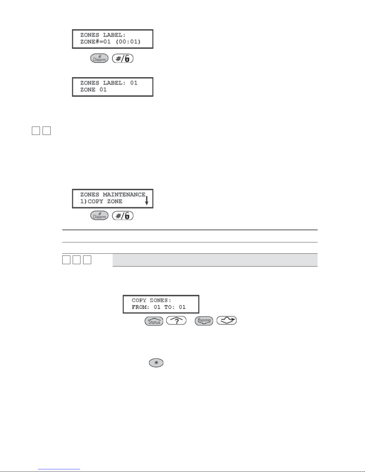
76 ProSYS Installation and Programming Manual
2 Press
/ to label Zone 01 (or enter another zone number). The following
display appears:
3 Refer to Entering a New Label Using the LCD Keypad, page 58, for details about how
to enter a label.
22 99
Zones: Maintenance
The Maintenance menu provides some useful tools for system maintenance.
To access the Maintenance menu:
1 Access the Zones menu, as described on page 62.
2 From the Zones menu, press [9] to access the Maintenance menu options. The
following display appears:
3 Press
/ .
4 Access and configure the parameters in the Maintenance menu, as follows:
Zones: Maintenance
Quick Keys Parameter
22 99 11
Copy to a Zone
Copies all the parameters belonging to a specified zone (except the Label
parameter).
1. Press [1]. The following display appears:
2. Use the / or / keys or the [1 to 9] keys to
select the zone from which a copy is to be made and the zone to which it is
being copied.
Using this function provides no confirmation before advancing to another
Copy Zone opportunity.
3. Press the
key to exit. The process is executed as the display is
changed.

ProSYS Installation and Pr ogramming Manual 77
Zones: Maintenance
Quick Keys Parameter
22 99 22
Delete a Zone
Deactivates a designated zone by setting its Zone Type to Not Used, while
maintaining all the previously programmed parameters.
1. Press [2].
2. Use the
/ or
/
keys or the [1 to 9] keys to
select the zone that is to be deleted. This process can also be used to
temporarily disable a zone from the protection scheme.
3. Confirm your choice by selecting either [Y] YES or [N] NO and pressing
/ .
4. Press the
key to exit. The process is executed as the display is
changed.
22 99 33
Add/Copy Partition
Assigns, to a designated partition, all the zones (and their respective
parameters) belonging to a specified partition, while keeping the original
partition intact.
For example, copying Partition 1 to Partition 2 simply duplicates all Partition 1's
zones in Partition 2.
1. Press [3].
2. Use the cursor keys to select the source and destination partitions.
Using this function provides no confirmation before advancing to another
Add/Copy Partition opportunity.
3. Press the
key to exit. The process is executed as soon as the display
is changed.
22 99 44
Delete a Partition
Deletes a designated partition. Selecting this option removes all zones
assigned to it, effectively removing the partition from the system.
1. Press [4].
2. Use the cursor keys to select the partition that you want to delete.
3. Confirm your choice by selecting either [Y] YES or [N] NO and pressing
/
.
4. Press the
key to exit.
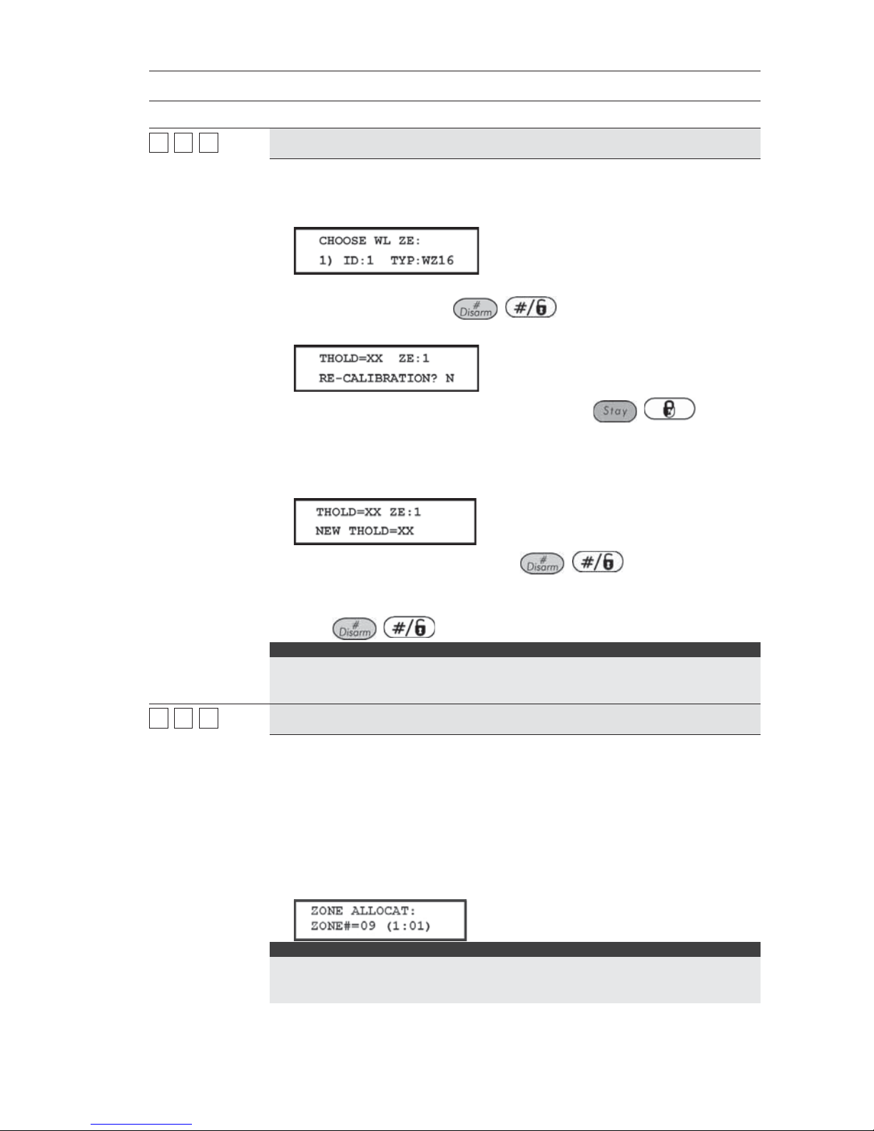
78 ProSYS Installation and Programming Manual
Zones: Maintenance
Quick Keys Parameter
22 99 55
Wireless Module Calibration
Measures the RF noise that the receiver is picking up. This is used for jamming
indication in order to eliminate false jamming alarms. The range is 00-99.
1. Press [5]. The following display appears:
2. Select the wireless zone expander for which you want to establish the
threshold level and press
/ . The following display appears,
showing the current threshold level:
3. To perform a new automatic calibration, use the / key to
select
[Y] YES.
After the calibration process is finished, the new receiving threshold is
displayed, as follows:
4. To confirm the new threshold, press / ,
-OR-
To change the threshold manually, enter the required level and
press
/ .
NOTES:
In order to ensure that a momentary high noise level (due to environmental
reasons) will not cause a jamming alarm, you can set the threshold level to be
higher than the calibrated level.
22 99 66
Wireless Zone Allocation
The following information relates to the assignment of zone attributes (for
example, Zone ID, Partition, Type, Sound, and so on) to any ProSYS wireless
detectors.
In order to receive data from wireless detectors, the ProSYS requires at least
one Wireless Zone Expander.
In order for the system to allocate a wireless detector, the system must first be
introduced to the detector, as follows:
Press [6]. The following display appears:
NOTE:
Wireless background information for the ProSYS is provided in the instructions
provided with the Wireless expansion module and the system's individual
transmitters.
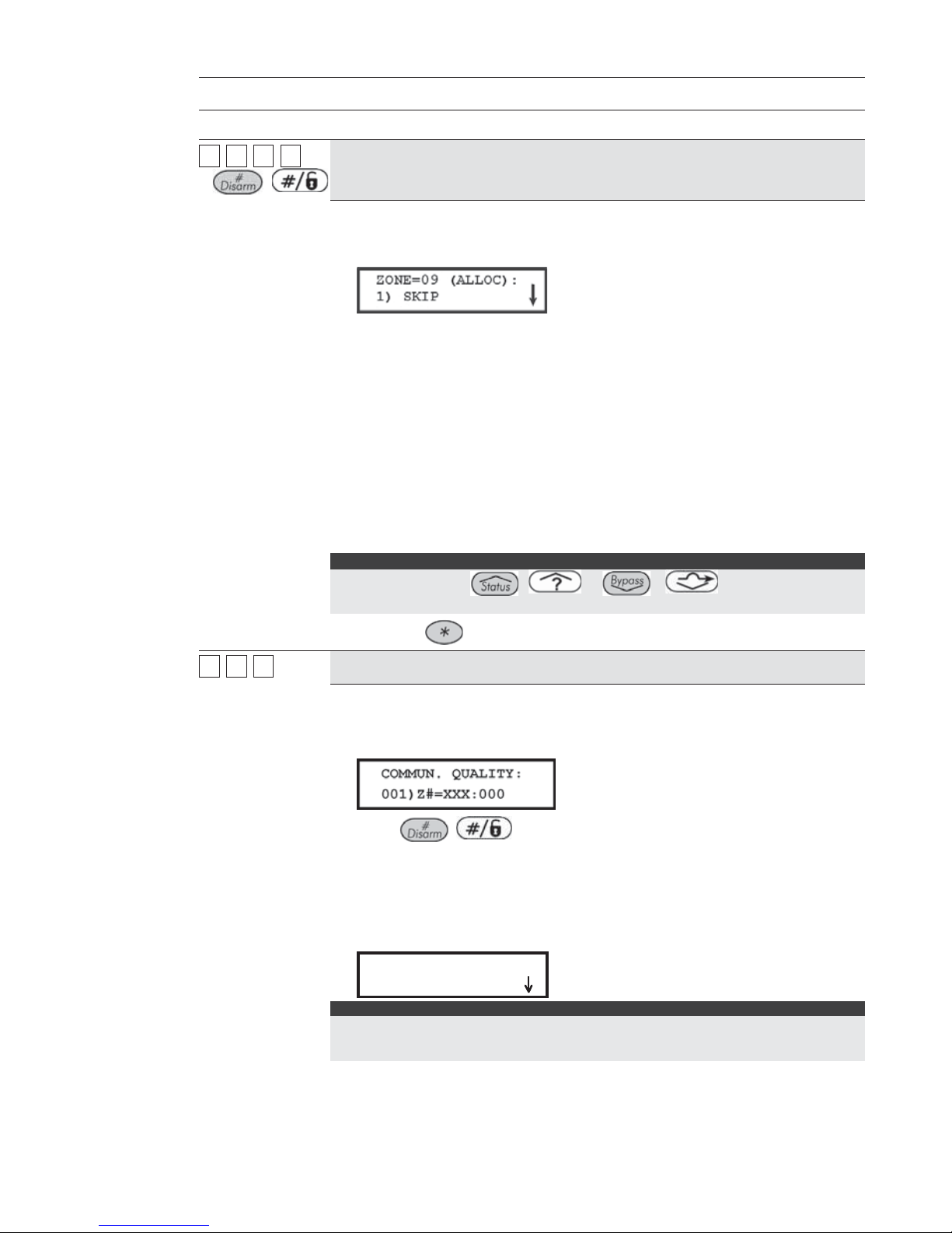
ProSYS Installation and Pr ogramming Manual 79
Zones: Maintenance
Quick Keys Parameter
22 99 66 ZZZZ
+
/
Wireless Zone Allocation Options
1. Select the zone number intended for the first wireless transmitter. The first
eight zones are reserved for the hardwired zones on the Main Panel. The
following display appears:
2. Press the required option, as follows:
O Press [1] to skip to the next transmitter assignment,
O -OR-
O Press [2] to overwrite the data into the selected location and
allocate the transmitter to a zone,
O -OR-
O Press [3] to erase the allocation data in the selected location
and then press [Y] YES or [N] NO to confirm your choice.
O -OR-
O Press [4] to choose supervision and then press [Y] YES or [N]
NO to confirm your choice.
NOTE :
You can also use the
/ or
/
keys to toggle
between the options and then press Enter.
3. Press the key to return to the higher programming level.
22 99 77
Wireless Communication Test
Performs a communication test between the transmitters and the receiver. The
value presented is a number between 00-99 that indicates the signal strength.
1. Press [7]. The following display appears:
2. Press / . The first wireless assigned zone appears.
3. In order to proceed, initiate a transmission from the selected zone. Allow a
few seconds for the receiver to react.
A number between 00-63 indicates the quality of communication with the
868.65 receivers or 00-99 with the 433.92 MHz receivers, as shown in the
following display:
COMMUN.QUALITY:
COMMUN.QUALITY:
01)ZONE=09 :63
01)ZONE=09 :63
COMMUN.QUALITY:
COMMUN.QUALITY:
01)ZONE=09 :63
01)ZONE=09 :63
NOTE:
For more successful communication the strength of the signal should be higher than the RF
noise that the receiver is picking up. If not, it is recommended to relocate the detector or the
receiver or to use a repeater.

80 ProSYS Installation and Programming Manual
Zones: Maintenance
Quick Keys Parameter
4. Use the / or / keys to select the zone
number for the next wireless transmitter.
5. Press the
key to return to the higher programming level.
22 99 88
Zone Self-Test
This feature provides an automated self-test for a selected group of localized
intrusion sensors (for example, glass break detectors, sound discriminators
and shock sensors) which respond to an artificial source of noise and/or
vibration.
Automated self-testing is especially useful when sensors are placed in high
security areas where failure cannot be tolerated.
Up to 16 zones can be designated for self-testing.
A sound or vibration generator should be used that can be placed close
enough to the sensors to trigger them when the noise source is activated.
A Utility Output acts as the source of switched power for the noise/vibration
generator (refer to Sensors Test, page 95). This is set to conform to the testing
schedule. The schedule defines the time and day for the first test and sets the
times for repeated tests over a 24-hour period.
A message is sent to the MS if all the related sensors are triggered during the
test (if a Report Code has been defined). Refer to Report Codes: MainTrouble,
page 142, for definitions.) With successful completion of the self-test, an entry
is also placed in the system's Event Log.
If, during the test period, one or more of the sensors fails to trip, a self-test
failure message is generated (refer to page 142) and sent to the MS. A record
of the failure is also entered in the Event Log.
Refer to the procedures on the following pages for details about setting up the
Zone Self-Test.

ProSYS Installation and Pr ogramming Manual 81
Zones: Maintenance
Quick Keys Parameter
CHOOSING ZONES FOR SELF-TESTING:
1. Press [8]. The following display appears:
2. Press / to specify the first of 16 possible zones for selftesting. The following display appears:
3. Enter the zone number of the first selected zone.
4. Use the
/ or / keys to position the cursor.
5. Press
/ .
6. Press
/ again, and repeat step 2, above, for the next
selected zone.
7. Continue this process until all zones are selected.
8. Press the
key to exit.
CHOOSING A TESTING SCHEDULE:
Default: 00 hours; 00 minutes
Range: 00 to 24 hours; 00 to 59 minutes
The following is a detailed procedure for using the Zone Test Times
parameter (Quick Keys [1] [1] [7], described on page 48.)
1. From the main Installer Programming menu, press [1] [1] and select option
[7]. The following display appears:
2. Press / . The following display appears:
3. Press / again. The following display appears:
4. Define the time (in 24-hour format) for the first test to begin. The defaults
are 00 hours and 00 minutes. The range is 00 to 24 hours and 00 to 59
minutes.

82 ProSYS Installation and Programming Manual
Zones: Maintenance
Quick Keys Parameter
5. Use the / or / keys to reposition the cursor.
6. Press
/ .
7. Press the
/ key once. The following display appears:
8. Press / . The following display appears:
9. Insert the time interval, in hours, between tests. The default is
00 hours. The range is 00 to 24 hours.
10. Press
/ . Press the key to exit.
SETTING UP THE UTILITY OUTPUT TO TRIGGER THE NOISE SOURCE:
(Refer also to Sensors Test, page 95.)
1. From the main Installer Programming menu, use the
/
or
/ keys to locate the following display:
NOTE:
You can also access this display by pressing [3].
2. Press / . The following display appears:
3. Choose a Utility Output to trigger the noise source by selecting an unused
UO number (for example, UO 1), using the numeric keys [0 to 9]. (Refer to
Wiring Zone Expansion Modules in Chapter 3, Installing External Modules
and Devices.)
4. Press
/ .
5. Press [1] to select System. The following display appears:
6. Press / . The following display appears:
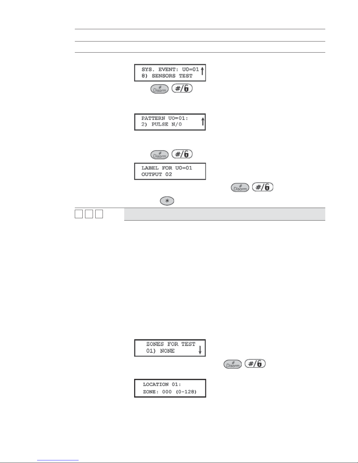
ProSYS Installation and Pr ogramming Manual 83
Zones: Maintenance
Quick Keys Parameter
7. Press [8] to select the sensors test. The following display appears:
8. Press / .
9. Select the manner in which the UO is to operate, by choosing [2] PULSE
N/O. The following display appears:
10. The UO, acting like a normally-open switch, is closed for a predetermined
period, completing a circuit that activates a noise source.
11. Press
/ . The keypad displays the label for the UO.
12. Accept or rename the label and press / .
13. Press the
key, as required, to return to the previous menus.
22 99 99
Soak Test
The Soak Test feature is designed to allow false alarming for predefined
detectors to be bypassed from the system, while any alarms generated are
displayed to the user for reporting to the
MS. This is especially useful if Police
response withdrawal is being threatened and a particular zone is causing
unidentified problems.
Up to 8 zones can be placed on Soak Test. Any zone placed in the Soak Test
list is bypassed from the system for 14 days and is automatically reinstated
after that time if NO alarms have been generated by it.
If a zone in the Soak Test list has an alarm during the 14-day period, the
keypad indicates to the user that the test has failed. After the user looks at the
View Trouble option (described in the ProSYS User's Manual), the trouble
message will be erased. This will be indicated in the event log, but no alarm
w
ill be generated. The alarmed zone's 14-day Soak Test period is then reset
and restarted.
1 From the Installer Programming menu, press quick keys
[2] [9] [9]. The following display appears:
2. To put a zone on Soak Test, press / . The following display
appears:
3. Press the keys as per the zone number (e.g. 001 for zone 1), as shown in
the following display:

84 ProSYS Installation and Programming Manual
Zones: Maintenance
Quick Keys Parameter
4. Press / .
5. To add a second zone for Soak Test, press / and repeat
the procedure above,
-OR-
Press the
key to return to the previous menu.
22 00
Zones: Miscellaneous
The Miscellaneous menu enables you to enable or disable the forced arming option, to define
number of pulses for a zone and define the parameters of BUS zones.
To access the Miscellaneous menu:
Access the Zones menu, as described on page 62.
1 From the Zones menu, press [0] to access the Miscellaneous menu options. The following
display appears:
2 Access and configure the parameters in the Miscellaneous menu, as follows:
Zones: Miscellaneous
Quick Keys Parameter Default Range
22 00 11
Forced Arming
DISABLED ENABLED/DISABLED
This option enables or disables the use of forced arming for each of the
system's zones, as follows:
If forced arming is enabled for a particular zone, it allows the system to be
armed even though this zone is faulted.
When a zone(s) enabled for forced arming is faulted, the keypad's READY/
LED blinks during the disarm period.
After arming, all zones enabled for forced arming are bypassed at the end of
the Exit Delay time period.
If a faulted zone (one enabled for force arming) is secured during the armed
period, it will no longer be bypassed and will be included among the
system's armed zones.

ProSYS Installation and Pr ogramming Manual 85
Zones: Miscellaneous
Quick Keys Parameter Default Range
1. Press [1] and then press / . The following display
appears:
2. Enter the number of the zone for forced arming and press / .
3. Use the
/ or / keys to select ENABLE or
DISABLE and press
/ . The following display appears:
4. Repeat steps 1 to 3 to change the forced arm status of any additional zone.
5. Press the
key to exit.
NOTE :
Report Codes for forced arming and zones bypassed in the process can be sent to
the MS (refer to page 147).
22 00 22
Pulsed Counter
01 01-15
Specifies that the zone will count the number of open and close pulses received.
If the zone exceeds the predefined number of pulses, the zone will be tripped
and act according to its type definition. After a 25-se cond timeout, the pulse
counter is restarted. The pulse length is the currently defined Loop Response
time period. (Refer to Zones: Loop Response, page 72.)
NOTES:
For zones with a loop response time of 1 ms (millisecond), the pulse count feature
w
ill be applicable only for zones on the zone expander RP128FZ0800A. Zones with
a loop response time between 0.5 hours and 4 hours will be applicable to the 8
zones on the Main Panel and to zones on the zone expander RP128FZ0800A.
The Pulsed Count feature is NOT applicable to the zones on the zone expanders
defined as ZE08, ZE16, WZ08, and WZ16.
1 Press [2] and then press / . The following
display appears:
2. Enter the number of the zone and press / . The following
display appears:
3. Define the number of pulses for the zone between 01-07.
4. Repeat steps 1 to 3 to define the pulse count for any additional zone, as
required.
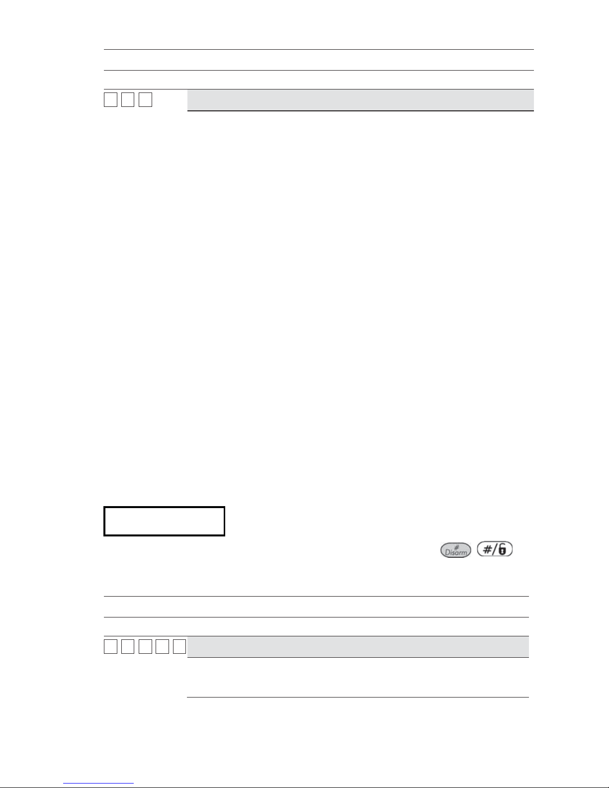
86 ProSYS Installation and Programming Manual
Zones: Miscellaneous
Quick Keys Parameter Default Range
22 00 33
BUS Zone Parameters
The BUS Zone Parameters menu contains parameters that enable you to
program the special parameters of a BUS zone. The options are determined
according to the BUS detector type:
♦ Lunar Grade 3: A dual technology ceiling detector with a mounting height of
up to 8.6m (28ft) that incorporates Anti-Cloak
TM
Technology (ACT).
♦ WatchOUT DT: A dual technology outdoor detector with signal processing
based on two Passive Infrared (PIR) channels and two Microwave (MW)
channels.
♦ WatchOUT PIR: An outdoor detector with signal processing based on two
Passive Infrared (PIR) correlated channels
♦ WatchIN DT Grade 3: A dual technology Grade 3 industrial detector with
signal processing based on two Passive Infrared (PIR) channels and two
Microwave (MW) channels.
♦ iWISE DT Grade 2: A motion detector incorporating the Anti-CloakTM
Technology (ACT). It adheres to environmentally friendly guidelines and is
available in 15m and 25m models
♦ iWISE QUAD Grade 2: A motion detector incorporating Quad PIR
technology
♦ iWISE DT Grade 3: A motion detector incorporating both Anti-Mask and
Anti-Cloak
TM
Technologies (ACT). It adheres to environmentally friendly
guidelines and is available in 15m and 25m models.
♦ iWISE QUAD Grade 3: A motion detector incorporating Anti-Mask and
Quad PIR technologies.
Use the instructions below to set parameters for the relevant BUS zone
detector.
To configure the BUS Zone detector parameters:
From the Miscellaneous menu, press [3] to access the BUS Zone parameters
menu options. The following display appears:
B-ZONE PRMS:
ZONE#=001 (M:ZZ)
B-ZONE PRMS:
ZONE#=001 (M:ZZ)
1 Select the zone that the BUS zone detector was assigned to and press
/ .
The BUS Zone parameters menu appears.
2 Use the below tables to configure the parameters for each BUS Zone detector type.
Zones Miscellaneous: BUS Zone – iWISE DT Grade 2
Quick Keys Parameter Default Range
22 00 33 ZZZZ 11
LEDS
On
Defines the LEDS operation mode.
[1] Off - Disables the LEDS operation.
[2] On - Enables the LEDS operation.

ProSYS Installation and Pr ogramming Manual 87
Zones Miscellaneous: BUS Zone – iWISE DT Grade 2
Quick Keys Parameter Default Range
22 00 33 ZZZZ 22 MW (Microwave) Range
Trimmer
Defines the microwave channel range.
[1] Minimum [2] 25% [3] 50% [4] 65% [5] 85% [6] Maximum [7] Trimmer (MW is
defined by the trimmer setting on the PCB)
22 00 33 ZZZZ 33 ACT
No
Defines the Anti-Cloak™ Technology (ACT) operation mode.
[1] No - Disables the ACT mode.
[2] Yes - Enables the ACT mode.
22 00 33 ZZZZ 44
Automatic Microwave
Bypass
No
Defines whether the MW channel will be bypassed or not while the detector
identifies trouble in the MW channel.
[1] No - While detecting a problem in the MW channel it is not bypassed. Alarm
condition cannot be established until the MW channel is fixed.
[2] Yes - Switches the detector to operate only in PIR mode in case of MW
trouble.
22 00 33 ZZZZ 55 Green Lin e
Yes
A feature that follows environmental guidelines by avoiding surplus emission
This feature defines the activation of the microwave channel while the system
is disarmed.
[1] No - Green Line feature is disabled. MW is constantly activated.
[2] Yes - Green Line feature is activated.
22 00 33 ZZZZ 66 Self Test
Remote
Used to test the detection technologies. In the event of a failed test, a Self Test
Trouble is created
[1] Remote (Manual) - The remote self test is performed by the system when a
user manually selects the Diagnostics option from the Maintenance menu via
the ProSYS User Functions menu
[2] Local (automatic) - Once an hour, the detector automatically checks that the
detector’s channels are functioning properly.
Zones Miscellaneous: BUS Zone – Lunar Grade 3/iWISE DT Grade 3
Quick Keys Parameter Default Range
22 00 33 ZZZZ 11
LEDS
On
Defines the LEDS operation mode.
[1] Off - Disables the LEDS operation.
[2] On - Enables the LEDS operation.
22 00 33 ZZZZ 22 MW (Microwave) Range
Trimmer
Defines the microwave channel range.
[1] Minimum [2] 25% [3] 50% [4] 65% [5] 85% [6] Maximum [7] Trimmer (MW is
defined by the trimmer setting on the PCB)

88 ProSYS Installation and Programming Manual
Zones Miscellaneous: BUS Zone – Lunar Grade 3/iWISE DT Grade 3
Quick Keys Parameter Default Range
22 00 33 ZZZZ 33
ACT
No
Defines the Anti-Cloak™ Technology (ACT) operation mode.
[1] No - Disables the ACT mode.
[2] Yes - Enables the ACT mode.
22 00 33 ZZZZ 44
Automatic Microwave
Bypass
No
Defines whether the MW channel will be bypassed or not while the detector
identifies trouble in the MW channel.
[1] No - While detecting a problem in the MW channel it is not bypassed. Alarm
condition cannot be established until the MW channel is fixed.
[2] Yes - Switches the detector to operate only in PIR mode in case of MW
trouble.
22 00 33 ZZZZ 55
Green Line
Yes
This option conforms to environmentally friendly standards by avoiding surplus
emission This feature defines the activation of the microwave channel while the
system is disarmed.
[1] No - Green Line feature is disabled. MW is constantly activated.
[2] Yes - Green Line feature is enabled.
22 00 33 ZZZZ 66
Anti-Mask
Enable
Defines the operation of Anti Masking detection.
[1] Disable [2] Enable and behaves according to the settings defined in quick
keys [2][0][3][zz][7].
22 00 33 ZZZZ 77
Arm/Disarm
No
Defines the operation of the anti masking detection while the detector is armed
or disarmed.
[1] No – While armed or disarmed, anti-mask behaves according to the setting
defined in quick keys [2][0][3][zz][6] above.
[2] Yes – While armed, anti-mask is disabled. When detector is disarmed Antimask behaves according to the settings defined in quick keys [2][0][3][zz][6].
22 00 33 ZZZZ 88
Self Test
Remote
Used to test detection technologies. In the event of a failed test, a Self Test
Trouble is created.
[1] Remote (manual) - Performed by the system when a user manually selects
the Diagnostics option from the Maintenance menu via the ProSYS User
Functions menu.
[2] Local (automatic) - Once an hour, the detector automatically checks that the
detector’s channels are functioning properly.

ProSYS Installation and Pr ogramming Manual 89
Zones Miscellaneous: BUS Zone – iWISE QUAD Grade 2
Quick Keys Parameter Default Range
22 00 33 ZZZZ 11 LEDS
On
Defines the LEDS operation mode.
[1] Off - Disables the LEDS operation.
[2] On – Enables the LEDS operation.
22 00 33 ZZZZ 22 Sensitivity
High
Defines the sensitivity of the detector (PIR).
[1] Low [2] High
22 00 33 ZZZZ 33 Self Test
Remote
Used to test detection technologies. In the event of a failed test, a Self Test
Trouble is created.
[1] Remote (manual) - Performed by the system when a user manually selects
the Diagnostics option from the Maintenance menu via the ProSYS User
Functions menu.
[2] Local (automatic) - Once an hour, the detector automatically checks that the
detector’s channels are functioning properly.
Zones Miscellaneous: BUS Zone – iWISE QUAD Grade 3
Quick Keys Parameter Default Range
22 00 33 ZZZZ 11 LEDS
On
Defines the LEDS operation mode.
[1] Off - Disables the LEDS operation.
[2] On – Enables the LEDS operation.
22 00 33 ZZZZ 22 Sensitivity
High
Defines the sensitivity of the detector (PIR).
[1] Low [2] High
22 00 33 ZZZZ 33
Anti-Mask
Enable
Defines the operation of Anti Masking detection.
[1] Disable [2] Enable and behaves according to the settings defined in quick
keys [2][0][3][zz][4]
22 00 33 ZZZZ 44 Arm/Disarm
No
Defines the operation of the anti masking detection while the detector is armed
or disarmed
[1] No – While armed or disarmed, anti-mask behaves according to the setting
defined in quick keys [2][0][3][zz][3] above.
[2] Yes – While armed, anti-mask is disabled. While detector is disarmed Antimask behaves according to the settings defined in quick keys [2][0][3][zz][3].

90 ProSYS Installation and Programming Manual
Zones Miscellaneous: BUS Zone – Lunar Grade 3/iWISE DT Grade 3
Quick Keys Parameter Default Range
22 00 33 ZZZZ 55
Self Test
Remote
Used to test detection technologies. In the event of a failed test, a Self Test
Trouble is created.
[1] Remote (manual) - Performed by the system when a user manually selects
the Diagnostics option from the Maintenance menu via the ProSYS User
Functions menu.
[2] Local (automatic) - Once an hour, the detector automatically checks that the
detector’s channels are functioning properly.
Zones Miscellaneous: BUS Zone – WatchOUT PIR
Quick Keys Parameter Default Range
22 00 33 ZZZZ 11
LEDS
3 LEDS
Defines the LEDS operation mode.
[1] Off - Disables the LEDS operation.
[2] Red Only - Only the Red LED will operate. This option is highly
recommended to avoid the possibility that a burglar will “Learn” the detector
behavior.
[3] 3 LEDS - All 3 LEDs will operate.
22 00 33 ZZZZ 22
PIR Sensitivity
Normal
Defines the PIR sensitivity of the detector.
[1] Low [2] Medium [3] Normal [4] High
22 00 33 ZZZZ 33
Lens Type
Wide Angl e
Defines the actual Lens of the detector.
[1] Wide Angle [2] Barrier / Long Range
22 00 33 ZZZZ 44
Auxiliary Relay Mode
Off
Defines the operation of the Auxiliary relay of the detector.
[1] Off - Auxiliary relay is disabled.
[2] 24 Hours - The auxiliary relay will always follow an alarm.
[3] Night Only - The auxiliary relay output will follow an alarm condition only
during night time. The time defined by the photocell on the PCB.
22 00 33 ZZZZ 55
Auxiliary Relay Time
2.2 seconds
Defines the time duration that the auxiliary relay is activated.
[1] 2.2 seconds [2] 2 minutes [3] 4 minutes [4] 8 minutes

ProSYS Installation and Pr ogramming Manual 91
Zones Miscellaneous: BUS Zone – WatchOUT DT
Quick Keys Parameter Default Range
22 00 33 ZZZZ 11 LEDS
3 LEDS
Defines the LEDS operation mode.
[1] Off - Disables the LEDS operation.
[2] Red Only - Only the Red LED will operate. This option is highly
recommended to avoid the possibility that a burglar will “Learn” the detector
behavior.
[3] 3 LEDS - All 3 LEDs will operate.
22 00 33 ZZZZ 22 PIR Sensitivity
Normal
Defines the sensitivity of the detector (MW + PIR).
[1] Low [2] Medium [3] Normal [4] High
22 00 33 ZZZZ 33
MW Range
Trimmer
Defines the microwave channel range (maximum range – 23m).
[1] Minimum [2] 20% [3] 40% [4] 60% [5] 80% [6] Maximum [7] Trimmer (MW is
defined by the trimmer setting on the PCB)
22 00 33 ZZZZ 44
Alarm Logic
PIR and Microwave
Determine the detector’s logic of defining an alarm.
[1] PIR and Microwave – An alarm is activated when both PIR and MW
channels detect an alarm (AND Logic).
[2] PIR or Microwave - An alarm is activated when either PIR or MW channels
detect an alarm (OR Logic).
22 00 33 ZZZZ 55 Lens Type
Wide Angle
Defines the actual Lens of the detector.
[1] Wide Angle [2] Barrier / Long Range
22 00 33 ZZZZ 66 Anti-Mask
Enable
Defines the operation of Anti Masking detection.
[1] Disable [2] Enable
22 00 33 ZZZZ 77
Arm/Disarm
No
Defines the operation of the LEDs and the anti masking detections while the
detector is armed.
1) No – While armed, LEDS and anti-mask behave according to the settings
defined in quick keys [2][0][3][zz][1] and [2][0][3][zz][6] above.
2) Yes – While armed, both LEDS and anti-mask are disabled.
22 00 33 ZZZZ 88 Prox Anti mask
Enable
Defines the operation of proximity anti masking detection.
[1] Disable [2] Enable

92 ProSYS Installation and Programming Manual
Zones Miscellaneous: BUS Zone – WatchIN DT Grade 3
Quick Keys Parameter Default Range
22 00 33 ZZZZ 11
LEDS
3 LEDS
Defines the LEDS operation mode.
[1] Off - Disables the LEDS operation.
[2] Red Only - Only the Red LED will operate. This option is highly
recommended to avoid the possibility that a burglar will “Learn” the detector
behavior.
[3] 3 LEDS - All 3 LEDs will operate.
22 00 33 ZZZZ 22
Detection Sensitivity
Normal
Defines the sensitivity of the detector (MW + PIR).
[1] Low [2] Medium [3] Normal [4] ACT (Anti-Cloak™ Technology)
22 00 33 ZZZZ 33
MW Range
Trimmer
Defines the microwave channel range (maximum range – 27m).
[1] Minimum [2] 20% [3] 40% [4] 60% [5] 80% [6] Maximum [7] Trimmer (MW is
defined by the trimmer setting on the PCB)
22 00 33 ZZZZ 44
Alarm Logic
PIR and Microwave
Determine the detector’s logic of defining an alarm.
[1] PIR and Microwave – An alarm is activated when both PIR and MW
channels detect an alarm (AND Logic).
[2] PIR or Microwave - An alarm is activated when either PIR or MW channels
detect an alarm (OR Logic).
22 00 33 ZZZZ 55
Lens Type
Wide Angle
Defines the actual Lens of the detector.
[1] Wide Angle [2] Barrier/Long Range
22 00 33 ZZZZ 66
IR Anti-Mask
Enable
Defines the operation of IR Anti Masking detection.
[1] Disable [2] Enable
22 00 33 ZZZZ 77
Arm/Disarm
No
Defines the operation of the LEDs and the anti masking detections while the
detector is armed.
[1] No – While armed, LEDS and anti-mask behave according to the settings
defined in quick keys [2][0][3][zz][1] and [2][0][3][zz][6] above.
[2] Yes – While armed, both LEDS and anti-mask are disabled.
22 00 33 ZZZZ 88
Green Line
Yes
This feature defines the activation of the microwave channel while the system
is disarmed.
[1] No - Green Line feature is disabled. MW is constantly activated.
[2] Yes - Green Line feature is enabled. This option conforms to
environmentally friendly standards by avoiding surplus emission.
22 00 33 ZZZZ 99
Sway
No
This option allows the recognition and immunity of swaying objects in a known
pattern.
[1] No - Sway is disabled.
[2] Yes - Sway is enabled.
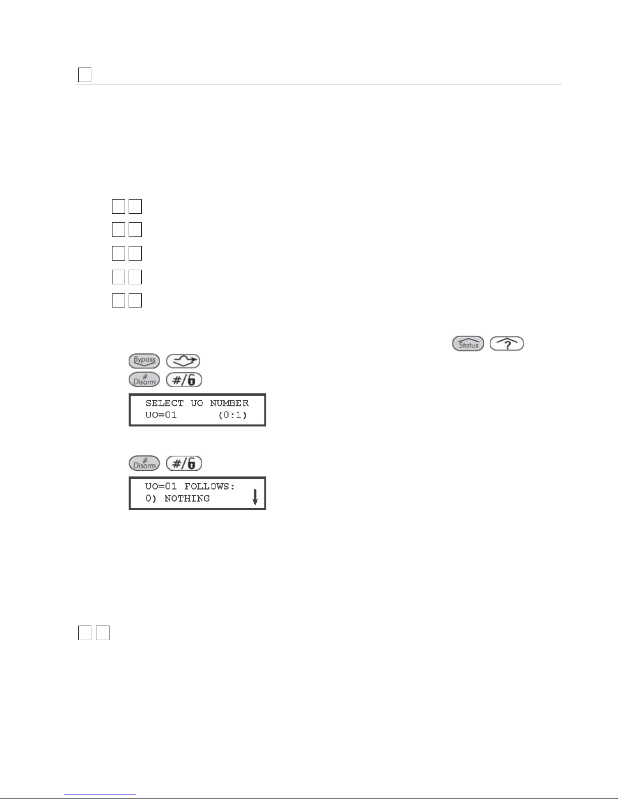
ProSYS Installation and Pr ogramming Manual 93
33
Utility Output
The Utility Output menu provides access to submenus and their related programming
parameters that enable you to choose the event that will trigger a selected Utility Output, as
well as the manner in which the output will be applied.
Adding one or more Utility Output expansion modules to the system makes an extensive list
of switched output possibilities available.
After you access the Utility Output menu from the main Installer Programming menu, as
described in this section, you can access the following submenus:
33 00
Nothing, page 93
33 11
System, page 94
33 22
Partition, page 96
33 33
Zone, page 99
33 44
Code, page 100
To access the Utility Output menu:
1 From the main Installer Programming menu, press [3], or press the / or
/ keys until you find the number [3] Utility Output option and then press
/ . The following display appears:
2 Enter a two-digit number for the Utility Output that you want to program, using a leading
zero for numbers between 1 and 9 (for example,
01, 02, and so on) and then press
/ . The following display appears:
You can now program the selected Utility Output. Use the information shown below. Each
of the system's Utility Outputs is assigned to a single type of event relating to one of the
following four major categories:
[1] System
[2] Partition
[3] Zone
[4] User Code
33 00
Utility Output: Nothing
The Nothing option enables you to disable the selected utility output.
To access the Nothing option:
Access the Utility Output menu and enter the appropriate two-digit number, as described on
page 93.

94 ProSYS Installation and Programming Manual
1 Press
/ to disable the selected utility output.
33 11
Utility Output: System
The System menu contains Utility Output parameters that follow the System Event.
To access the System menu:
Access the Utility Output menu, as described on page 93.
1 From the Utility Output menu, press [1] to access the System menu options. The following
display appears:
2 Press
/ . The following display appears:
3 Access and configure the parameters in the System menu, as follows:
Utility Output: System
Quick Keys Parameter
33 11 0101
Bell Follow
Activates when a bell is triggered.
If a bell delay was defined, the Utility Output will be activated after the delay
period. (Refer to Bell Delay, page 47.)
33 11 0202
No Telephone Line
Activates in the following cases:
1. When a telephone line fault is detected. If a Phone Line Cut Delay time
period is defined, the Utility Output will be activated after the delay time. (Refer
to Phone Line Cut Delay Time, page 48.)
2. When the AGM module is connected to the ProSYS, the Line Fault output is
activated when there is a loss of phone line simulation connection between the
AGM Module and the ProSYS (meaning there is both AGM and PSTN loss).
Deactivates after the telephone line fault has been corrected.
33 11 0303
Communication Failure
Activates when communication with the MS cannot be established.
Deactivates after a successful call is established with the
MS.
33 11 0404
Trouble Follow
Activates when a system trouble condition is detected.

ProSYS Installation and Pr ogramming Manual 95
Utility Output: System
Quick Keys Parameter
33 11 0505
Ground Pulse
Activates when the ProSYS dialer dials out.
This option is rarely used and is intended for older phone systems that require
a "Ground Start" (a momentary connection between one side of the phone line
and "earth") to obtain a dial tone.
When the Utility Output is programmed (and properly wired) for this purpose, it
provides the 2-3 pulses needed to furnish a dial tone to the dialer.
If the Ground Pulse parameter is used, the Pattern of Operation options,
page 100, do not apply.
33 11 0606
Low Battery Follow
Activates when the ProSYS rechargeable standby battery has insufficient
reserve capacity and the voltage decreases to 11.5V.
33 11 0707
AC Loss Follow
Activates when the source of the Main Panel's AC power is interrupted. This
activation will follow the delay time defined in the system control times and the
AC Off Delay Time parameter (refer to page 48).
33 11 0808
Sensors Test
Relates to the ProSYS Zone Self-Test (Quick Keys [2][9][8]) described on
page 80.
This option is selected if the designated Utility Output is part of the circuit
providing switched power for the source of noise (or vibration) used in the
Sensors Test procedure.
33 11 0909
Voice Module
When a Follow-Me number is dialed due to an alarm, this Utility Output
activates the Voice module (RP200VC), which plays a pre-programmed
message repeatedly. The Utility Output deactivates after the Follow-Me period
is completed.
33 11 1010
Battery Test
A pulsed Utility Output will follow the Battery Test only once a day at 9:00 AM.
The pulse interval is 10 seconds. This parameter is usually used to perform an
overload test on the system by using an external device.
33 11 1111
Bell Burglary
Activates the Utility Output after any bell burglary alarm in any partition in the
system.
33 11 1212
Scheduler
The Utility Output will follow the predefined time programming that is defined in
the scheduler of the weekly programs for Utility Output activation. For
additional details, refer to the ProSYS User's Manual.

96 ProSYS Installation and Programming Manual
Utility Output: System
Quick Keys Parameter
33 11 1313
Digital Key Reader Communication
This Utility Output is activated when there is a BUS communication problem
w
ith the Proximity Key Reader. The pattern of the operation is Pulsed, and the
default is 01 second for the pulse duration.
The Utility Output will be activated for 5 consecutive times between the time
that the Main Panel identifies a communication problem with the Digital Key
Reader and the time it sends a restore event.
33 11 1414
Switch AUX
Activates the Utility Output when a fire zone is activated (for fire detection)
according to the time defined in Double Verification of Fire Alarms, page 50.
This Utility Output will not have the option to choose pulse or latch in the
Pattern of Operation. The pulse time is defined in Switched Auxiliary Break,
page 47.
33 11 1515
GSM Error
Relates to GSM/GPRS module. Activates the utility output in the following
cases:
♦ There is no SIM card in the GSM/GPRS BUS Module or SIM is faulty
♦ GSM RSSI signal level is low
♦ GSM network fault
33 11 1616
GSM: PSTN Loss
Relates to GSM/GPRS module. Activates following a loss of PSTN line
(connected to the GSM).
NOT E:
This parameter is relevant only for GSM/GPRS full version module.
33 11 1717
GSM Low Battery
Relates to GSM/GPRS module. Activates the utility output when the GSM back
up battery voltage drops below 11VDC.
4 Press / and proceed to Pattern of Operation, page 100, to set the
pattern and duration of operation.
33 22
Utility Output: Partition
The Partition menu contains Utility Output parameters that follow the Partition Event. The
Utility Output can follow any partition(s) combination.
To access the Partition menu:
Access the Utility Output menu, as described on page 93.
1 From the Utility Output menu, press [2]. The following display appears:
2 Press
/ to access the Partition menu options. The following display
appears:

ProSYS Installation and Pr ogramming Manual 97
3 Select the partition event to be followed from those listed below, using the
/
or / keys to move the cursor left or right, respectively.
Utility Output: Partition
Quick Keys Parameter
33 22 0101
Ready Follow
Activates the Utility Output when all the selected partition(s) are in the READY
state.
33 22 0202
Alarm Follow
Activates the Utility Output when an alarm occurs in the selected partition(s).
33 22 0303
Arm Follow
Activates the Utility Output when the selected partition(s) is armed in either the
AWAY or STAY mode. The Utility Output will be activated immediately,
regardless of the Exit Delay time period.
33 22 0404
Burglary Follow
Activates the Utility Output when a BURGLARY (intrusion) alarm occurs in the
selected partition(s).
33 22 0505
Fire Follow
Activates the Utility Output when a FIRE alarm is triggered in the selected
partition(s) or when alarm keys [4] and [5] (FIRE) are pressed simultaneously.
33 22 0606
Panic Follow
Activates the Utility Output when a PANIC alarm is triggered in the selected
partition(s) or when alarm keys [1] and [2] (PANIC) are pressed
simultaneously.
33 22 0707
Special Emergency Follow
Activates the Utility Output when an AUXILIARY EMERGENCY alarm is
triggered in the selected partition(s) or when alarm keys [7] and [8] are
pressed simultaneously.
33 22 0808
Duress Follow
Activates the Utility Output when a DURESS alarm is initiated at the keypad
related to the selected partition(s).
To deactivate this Utility Output in a latch pattern, refer to the User menu
option Duress Reset ([2][9][3]) (described in the ProSYS User's Manual).
33 22 0909
Buzzer Follow
Activates the Utility Output when a keypad in the selected partition(s) sounds
its BUZZER during Auto Arming, Exit/Entry Delays, and alarm conditions.
33 22 1010
Chime Follow
Activates the Utility Output when a keypad in the selected partition(s) sounds
its CHIME.

98 ProSYS Installation and Programming Manual
Utility Output: Partition
Quick Keys Parameter
33 22 1111
Exit/Entry Follow
Activates the Utility Output when the selected partition(s) initiates an Exit/Entry
Delay period.
33 22 1212
Fire Trouble Follow
Activates the Utility Output when a FIRE TROUBLE is detected in the selected
partition(s).
33 22 1313
Day (Zone) Trouble
Activates the Utility Output when a DAY ZONE TROUBLE is detected in the
selected partition(s).
33 22 1414
General Trouble Follow
Activates the Utility Output when a TROUBLE condition is detected in the
selected partition.
33 22 1515
Stay Follow
Activates the Utility Output when the selected partition(s) is armed in STAY
mode.
33 22 1616
Tamper Follow
Activates the Utility Output when a Tamper occurs in the selected partition(s)
and follows any type of tamper.
33 22 1717
Disarm Follow
Activates the Utility Output when the selected partition(s) is disarmed.
33 22 1818
Bell Follow
Activates the Utility Output when one of the defined partitions is in ALARM
mode and the bell is triggered. This enables the connection of different sirens
to different partitions.
33 22 1919
Bell Stay Off
This parameter causes the Utility Output to function as follows:
♦ In AWAY ARMING mode, the Utility Output will follow the bell activation in
the defined partitions.
♦ In STAY ARMING mode, the Utility Output will not be activated.
NOT E:
If an alarm occurs in a zone that shares more than one partition and one of the
partitions is in ARM mode (while the other is in STAY mode), the Utility Output
will be activated, as described above.
♦ In STAY mode, a 24-hour zone will not activate this Utility Output.
33 22 2020
Zone Bypass
Activates the Utility Output when the relevant partitions are in ARM or STAY
mode and any zone in the relevant partitions is bypassed.
33 22 2121
Automatic Arm Alarm
Automatically activates an alarm when an event occurs.

ProSYS Installation and Pr ogramming Manual 99
Utility Output: Partition
Quick Keys Parameter
33 22 2222
Zone Loss Alarm
An alarm is activated when a wireless zone is lost.
4 Press / . The following display appears:
NOTE:
The XX in the UO =XX refers to the number of the Utility Output currently being programmed.
5 Use the
/ key to toggle between [Y] YES and [N] NO to designate the
partition(s) that will activate the selected Utility Output (UO),
-OR-
Press the partition number [1 to 8] to select or deselect it.
6 Press
/ and proceed to Pattern of Operation, page 100, to set the
pattern and duration of operation.
33 33
Utility Output: Zone
The Zone menu contains Utility Output parameters that follow the Zone Event. Each Utility
Output can be activated by a group of up to five zones.
To access the Zone menu:
Access the Utility Output menu, as described on page 93.
1 From the Utility Output menu, press [3]. The following display appears:
2 Press
/ to access the Zone menu options. The following display
appears:
3 Select the zone event type to be followed from the following list:
Utility Output: Zone
Quick Keys Parameter
33 33 11
Zone Follow
Activates the Utility Output when the selected zone is tripped.
The tripped zone need not be armed to trigger the Utility Output.
33 33 22
Alarm Follow
Activates the Utility Output when the selected zone causes an alarm.
33 33 33
Arm Follow

100 ProSYS Installation and Programming Manual
Utility Output: Zone
Quick Keys Parameter
Activates the Utility Output when the selected zone is armed by the system.
33 33 44
Disarm Follow
Activates the Utility Output when the selected zones are disarmed.
4 Press / . The following display appears:
5 Enter the zone numbers in the group and press
/ after each one. For
each Utility Output, you can define a group of up to five zones.
NOTE:
If you choose a zone number that is not in the system, a broken line is displayed (---).
6 Press
/ and proceed to Pattern of Operation, page 100, to set the
pattern and duration of operation.
33 44
Utility Output: User Code
The Code menu parameters enable you to program the activation of the selected Utility
Output when the user chooses the User Functions menu (selects ACTIVITIES/UTIL
OUTPUT, enters an authorized User Code and presses press
/ ). The Installer
designates the User Code(s) for triggering the selected UO.
Refer to the ProSYS User's Manual for additional details about triggering Utility Output(s) via
User Codes.
NOTE:
The Utility Output will be activated by entering a User Code only if the Quick UO parameter under System
Control is defined as Disabled. When the Quick UO is defined as Enabled, no User Code is required.
To access the Code menu:
Access the Utility Output menu, as described on page 93.
1 From the Utility Output menu, press [4]. The following display appears:
2 Press
/
to access the Code menu options. The following display
appears:
3 Use the
/ or / keys to select from any of the 99 available
User Codes.
4 Use the
/ key to toggle between [Y] YES or [N] NO for each user
chosen to trip the designated Utility Output.
5 Press / and proceed to the following Pattern of Operation submenu to
set the pattern and duration of operation:
 Loading...