

Page 1
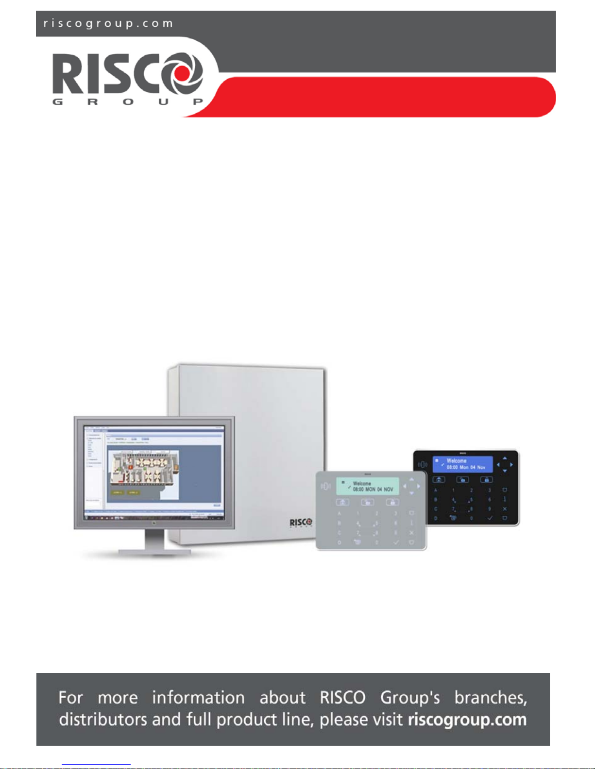
ProSYS
™
Plus
Quick Installer Guide
See the ProSYS Plus Installation and Programming Manual at
www.riscogroup.com for additional, detailed information.
Page 2

09/2016 Page 2 5IN2371 C
Contents
GETTING STARTED ....................................................................................... 6
Main Steps for Initial System Setup ............................................................................. 6
IMPORTANT SAFETY PRECAUTIONS ...................................................... 7
INSTALLATION ............................................................................................... 8
Step 1: Creating a Plan for Mounting the System ........................................................ 8
Main Panel Mounting Guidelines................................................................................. 8
Step 2: Wiring, Settings, and Module Installations at the Main Panel ......................... 8
Power Supply, Ground Wiring and Telephone Wiring ................................................. 8
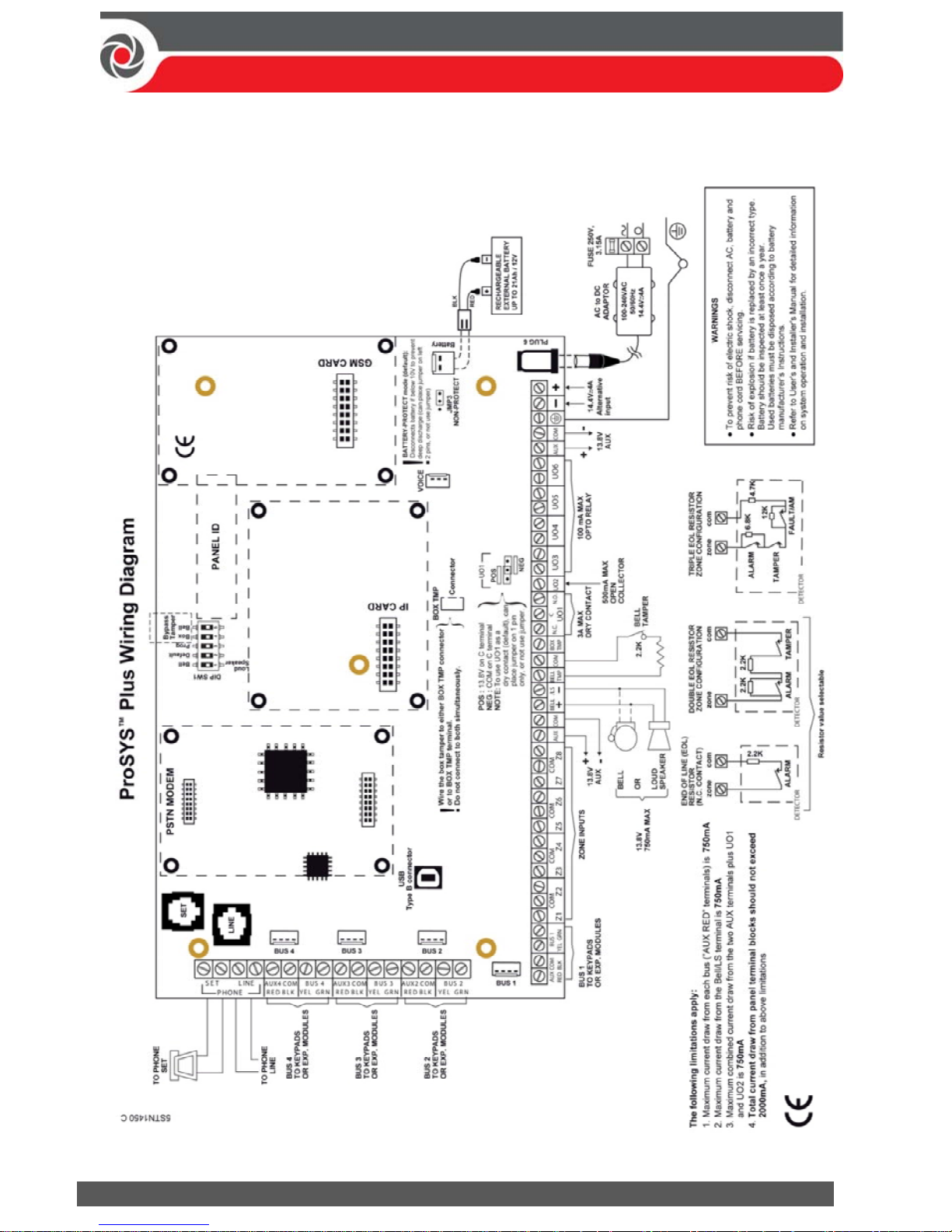
Main Panel Wiring Diagram ....................................................................................... 10
Replacing the Main Panel PCB ................................................................................... 11
Setting Main Panel DIP Switches and Jumpers .......................................................... 11
Installing Plug-In Communication & Audio Modules ................................................. 11
Installing a GSM Module ....................................................................................... 11
Installing a SIM Card ......................................................................................... 12
Installing an IP Module .......................................................................................... 12
Installing the PSTN Modem Module ..................................................................... 12
Installing an LRT Module ....................................................................................... 12
Installing the Voice Module .................................................................................. 12
Installing the Listen-In Unit ................................................................................... 12
Wiring other Devices at the Terminal Block............................................................... 12
Installing a Wired Keypad ................................................................................... 12
Connecting Auxiliary (12 V DC) Devices ................................................................ 13
Connecting the Bell / Loudspeaker ....................................................................... 13
Connecting the Bell Tamper .................................................................................. 14
Connecting the Box Tamper (Wall Tamper) .......................................................... 14
Connecting Utility Output 1 .................................................................................. 15
Placing the JMP 2 (UO1) Jumper ...................................................................... 15
Step 3: Bus Line Installations ..................................................................................... 16
Bus Line Wiring .......................................................................................................... 16
Describing Bus Devices .............................................................................................. 16
Describing Bus Detectors and their Connection Options ........................................... 16
Page 3

09/2016 Page 3 5IN2371 C
Wired Expansion Modules Installed on RISCO Bus Lines .......................................... 17
Describing Installer-Set ID Numbers for Bus Devices ................................................ 18
ID Number Formats .............................................................................................. 19
Assigning ID Numbers (Setting DIP Switches) for Bus Devices ............................. 20
Installing Bus Devices ................................................................................................ 21
Installing Wired Keypads ...................................................................................... 21
Connecting Individual Bus Detectors to a Bus at the Main Panel ........................ 21
Connecting Multiple Bus Detectors using Bus Zone Expanders ........................... 22
Step 4: Connecting Relay Detectors ........................................................................... 23
Defining Zone Termination Resistance ...................................................................... 24
Wiring Resistors for Zone Termination Resistance ............................................... 24
Zone Termination Configuration Options ............................................................. 24
Step 5: Connecting the Backup Battery and Mounting the Main Panel ...................... 25
Connecting the Backup Battery ................................................................................. 25
Mounting the Main Panel.......................................................................................... 25
SYSTEM INITIALIZATION, DEVICE ALLOCATION, GENERAL
SYSTEM CONFIGURATION ....................................................................... 26
Step 1: Working with the Keypad and Installer Menus .............................................. 26
Describing Dynamic Keypad Menus .......................................................................... 26
Table of Menu Navigational Keys ......................................................................... 26
Designating Labels ................................................................................................ 26
Entering the Installer Programming Menu at Initial System Setup ........................... 27
Subsequently Accessing Installer Menus .................................................................. 27
Step 2: Powering-Up and Initializing the System ....................................................... 27
Initial System Power-Up and Language Selection ..................................................... 27
Viewing Zones, Defining Partitions, and Setting the Time & Date ............................ 28
Viewing Zones, Defining Partitions, and Setting Time/Date at Initialization ........ 28
Viewing & Updating Zones and Defining Partitions after Initialization ................ 29
Step 3: Allocating and Configuring Installed Components ......................................... 30
Auto-Setting Allocation of Communication Modules and Bus Devices ..................... 30
Describing Auto-Setting Results ........................................................................... 31
Performing a Bus Test ............................................................................................... 31
Manually Allocating & Configuring Communication Modules .................................. 32
GSM Modules ....................................................................................................... 32
Page 4
09/2016 Page 4 5IN2371 C
Entering or Deleting a SIM Card PIN ................................................................. 32
Defining APN Automatically and Manually ...................................................... 33
IP Modules ............................................................................................................ 33
Setting Dynamic IP / Static IP ........................................................................... 33
PSTN Modem Module ........................................................................................... 33
Long-Range Radio Transmitter Module ................................................................ 33
Manually Allocating & Configuring other Modules and Bus Devices ......................... 34
Wired Keypads ...................................................................................................... 34
Zone Expanders ..................................................................................................... 35
Utility Output Modules ......................................................................................... 35
Power Supply Modules ......................................................................................... 35
Wireless Expanders ............................................................................................... 36
Proximity Key Readers .......................................................................................... 36
Voice Module ........................................................................................................ 36
Sounders (Sirens) .................................................................................................. 37
Bus Zones (Bus Detectors) .................................................................................... 37
Bus Zone Expanders .............................................................................................. 38
Step 4: Allocating Wireless Zones .............................................................................. 39
Allocating Wireless Expanders ................................................................................... 39
Allocating Wireless Devices ....................................................................................... 39
Sending Wireless Device RF Transmissions ........................................................... 40
Step 5: Basic Zone Configuration for All Zone Types .................................................. 41
Defining Basic Parameters ......................................................................................... 41
Describing Zone Information Displayed at the Keypad ......................................... 41
Defining Zone Parameters using the “One-By-One” Option ................................. 42
Defining Zone Parameters using the “By Category” Option ................................. 43
Defining Zone Termination Resistance using the “Resistance” Option ................ 43
Zone Termination Resistance Values (in Ohms) ............................................... 44
Step 6: Advanced Zone Configuration for Bus Zones and Wireless Zones .................. 44
Advanced Programming for Bus Zones ...................................................................... 44
Advanced Programming for Wireless Zones .............................................................. 44
Measuring Background Noise Level and Defining its Threshold Limit .................. 45
Performing a Wireless Comm. Test for Measuring Signal Strength ...................... 46
Step 7: Configuring System Communication .............................................................. 47
Defining Primary Communication Channels & Parameters ....................................... 47
Page 5

09/2016 Page 5 5IN2371 C
Defining Communication with the Monitoring Station ............................................. 48
Enabling Monitoring Station Communication ...................................................... 48
Defining Monitoring Station Account Parameters ............................................... 48
Step 8: Configuring Cloud Connectivity ...................................................................... 49
Enabling / Disabling Cloud Communication .............................................................. 49
Defining RISCO Cloud Connectivity ........................................................................... 49
Step 9: Configuring Common System Parameters ...................................................... 50
Defining System Users ............................................................................................... 50
Defining User Codes ............................................................................................. 50
Changing the Default Installer Code ..................................................................... 50
Changing the Default Grand Master Code ........................................................... 51
Defining Follow Me Destinations .............................................................................. 51
Enabling Follow Me .............................................................................................. 51
Defining Follow Me Parameters ........................................................................... 51
Defining System Timers ............................................................................................. 51
INSTALLER PROGRAMMING ................................................................... 52
Step 1: Defining Additional Parameters in the Installer Programming Menu ............. 52
Step 2: Exiting Installer Programming Menu after Initial System Configuration......... 52
Step 3: Defining Parameters in other Installer Menus ............................................... 52
TESTING THE SYSTEM .............................................................................. 53
INSTALLER RESPONSIBILITIES FOR ASSISTING CLIENTS ............ 53
TECHNICAL SPECIFICATION ................................................................... 54
LICENSING PROCEDURE ........................................................................... 56
Page 6

09/2016 Page 6 5IN2371 C
Getting Started
This guide covers the main tasks required to install and set up the ProSYS Plus
system. Installation and setup should be performed by a professional alarm system
installer. For additional comprehensive details, refer to the ProSYS Plus Installation
and Programming Manual.
Main Steps for Initial System Setup
INSTALLATION
Step 1: Creating a Plan for Mounting the System
Step 2: Wiring, Settings, and Module Installations at the Main Panel
Step 3: Bus Line Installations
Step 4: Connecting Relay Detectors
Step 5: Connecting the Backup Battery and Mounting the Main Panel
SYSTEM INITIALIZATION, DEVICE ALLOCATIONS & GENERAL SYSTEM
CONFIGURATION
Step 1: Working with the Keypad and Installer Menus
Step 2: Powering-Up and Initializing the System
Step 3: Allocating and Configuring Installed Components
Step 4: Allocating Wireless Zones
Step 5: Basic Zone Configuration for All Zone Types
Step 6: Advanced Zone Configuration for Bus Zones and Wireless Zones
Step 7: Configuring System Communication
Step 8: Configuring Cloud Connectivity
Step 9: Configuring Common System Parameters
INSTALLER PROGRAMMING
Step 1: Defining Additional Parameters in the Installer Programming Menu
Step 2: Exiting Installer Programming Menu after Initial System Configuration
Step 3: Defining Parameters in other Installer Menus
TESTING THE SYSTEM
INSTALLER RESPONSIBILITIES FOR ASSISTING THE CLIENT
Page 7
09/2016 Page 7 5IN2371 C
Important Safety Precautions
WARNING: Installation or usage of this product that is not in accordance
with the intended use and manufacturer instructions can result in damage,
injury or death. The system is NOT meant to be installed or serviced by those
other than professional security alarm system installers.
WARNING: Make sure this product is not accessible by those for whom
operation of the system is not intended, such as children.
WARNING: The main panel should be connected to an easily-accessible wall
outlet so that power can be disconnected immediately in case of malfunction
or hazard. If it is permanently connected to an electrical power supply, then
the connection should include an easily-accessible disconnection device, such
as a circuit breaker.
WARNING: Coming into contact with 230 VAC can result in death. If the
main panel is open while it is connected to the electrical power supply, do
not touch any AC electrical wiring to/from the mains fuse terminals nor the
mains fuse terminals.
WARNING: Ensure proper grounding requirements are implemented for the
system and peripherals, where required.
WARNING: Replace battery with correct type to avoid the risk of explosion.
CAUTION: Dispose of batteries according to applicable law and regulation.
Page 8

09/2016 Page 8 5IN2371 C
Installation
Step 1: Creating a Plan for Mounting the System
NOTE: For main panel installation, see the box/enclosure instructions. See the
ProSYS Plus Installation and Programming Manual for wireless system mounting
considerations.
Main Panel Mounting Guidelines
Before you mount the main panel and peripheral components, make a plan for
obtaining the most optimal location for the panel, which (depending on
configuration-specific requirements) should typically be:
Centrally located for minimizing lengthy bus line/ expansion module wire runs
In a location with good GSM reception
In a secure location that is hidden and not reachable by those for whom use is
unintended (such as small children)
Near an uninterrupted 230 VAC electrical outlet, an easily-accessible disconnection
device such as a circuit breaker (if permanently connected to the electrical power
supply), grounding connection, and network cable outlet, as needed
In a dry place, away from sources of electrical and RF disturbance, and not near
large metal objects which may hinder reception
Step 2: Wiring, Settings, and Module Installations at
the Main Panel
Power Supply, Ground Wiring and Telephone Wiring
IMPORTANT: AC wiring should be performed by a certified electrician, and in
compliance with applicable electrical code, laws and regulation. See the ProSYS Plus
Installation and Programming Manual and the box/enclosure instructions. The electrical
power rating is specified on the label located next to the fuse.
The main panel should be connected to an easily-accessible wall outlet so that
electrical power can be disconnected immediately in case of malfunction or hazard. If
it is permanently connected to an electrical power supply, then the connection should
include an easily-accessible disconnection device, such as a circuit breaker
Page 9
09/2016 Page 9 5IN2371 C
WARNINGS:
To prevent risk of electric shock, do not apply electrical power to the main panel nor
connect the main panel’s backup battery at any time during installation or servicing.
The panel is not to be powered up until system initialization (Step 2: Powering-Up and
Initializing the System, page 27).
Under no circumstances should a mains power cable be connected to the main
panel/PCB other than to the mains fuse terminal block.
Replace the fuse only with one of the same type and rating (250 V, 3.15 A).
To connect the power supply and ground wiring:
1. Do not connect AC power at this point of the installation.
2. Refer to the box/enclosure instructions.
3. ProSYS Plus is powered by a RISCO-supplied AC/DC adaptor (100-240V,
50/60Hz, 14.4V, 4A) that is pre-installed inside the main panel box/enclosure.
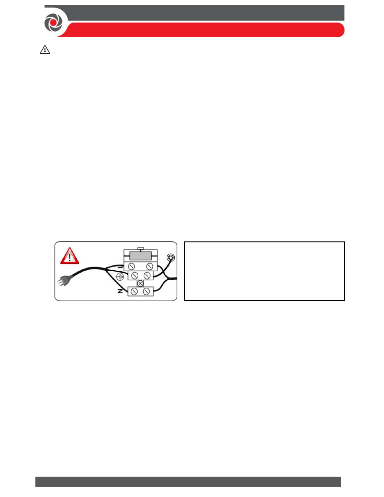
Connection to AC must be permanent and connect through the mains-fuse
terminal block as follows:
IMPORTANT:
For grounding requirements of all system components, see the ProSYS
Plus Installation and Programming Manual.
4. Ensure correct ground wiring as follows:
a. At the center (ground) fuse terminals shown above, ensure that one center
terminal is wired to the box/enclosure. Then wire the power cable’s
ground wire to the other center terminal.
b. A ground wire connects between the box/enclosure and its cover. Refer to
the box/enclosure instructions for details.
5. [For PSTN]: At the terminal block on the main panel PCB, connect the telephone
line to the Line terminals (or PLUG10 jack) and connect the telephone to the Set
terminals (or PLUG9 jack). See Main Panel Wiring Diagram, page 10.
IMPORTANT: Clamp power cable wires to
the box/enclosure housing using plastic ties,
and thread them through the arched tie-down
brackets on the base of the box/enclosure
housing (see box/enclosure instructions).
Page 10
09/2016 Page 10 5IN2371 C
Main Panel Wiring Diagram
Page 11
09/2016 Page 11 5IN2371 C
Replacing the Main Panel PCB
If replacing the main panel PCB, in order to prevent bus sirens from sounding,
before you power-off the main panel, first enter the installer Programming mode.
Then you can power-off the main panel and replace the PCB assembly.
Setting Main Panel DIP Switches and Jumpers
NOTE: For main panel jumper settings and descriptions of ports and connectors on
the main panel PCB, see the ProSYS Plus Installation and Programming Manual.
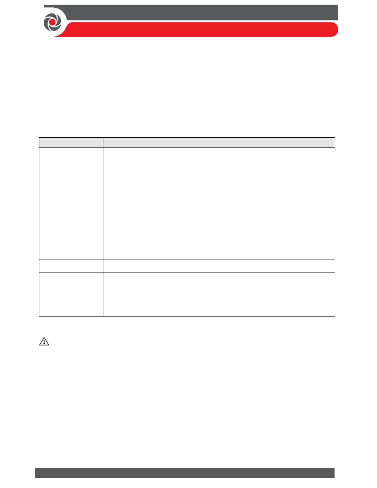
DIP switch (SW1) Status
1: Bell
ON: Bell: For a bell or electronic siren with a built-in siren driver.
OFF: (Default): For a loudspeaker without a built-in sound driver.
2: Default
ON: Intended for installer programming at initial system setup (from
the installer Programming menu), this setting allows the installer
to set the language, time and date. Caution: If set to ON any time
after exiting the installer Programming menu, it will reset
installer, sub-installer and Grand Master codes to factory
defaults.
OFF: (Default): For after exiting installer Programming menu – such as
during installer programming from other installer menus (other
than Programming menu), and during regular system operation.
3: Program
OFF (default). NOTE: Not to be set by installer— for factory use only.
4: Box tamper
bypass
ON: Box tamper protection is bypassed (not active)
OFF: (Default): Box tamper protection is not bypassed (active)
5: Bell tamper
bypass
ON: Bell tamper protection is bypassed (not active)
OFF: (Default): Bell tamper protection is not bypassed (active)
Installing Plug-In Communication & Audio Modules
CAUTION: Before installing any communication or audio module, in order to
prevent damage to system components, make sure the main panel is NOT
powered up, and that the panel’s backup battery is DISCONNECTED.
NOTE: See the installation instructions included with each module, and the Main
Panel Wiring Diagram for module connection locations on the PCB. Also see the
ProSYS Plus Installation and Programming manual for further details.
Installing a GSM Module
GSM modules provide voice and data communication over a cellular network. The
G2 and G3 GSM modules provide generation 2 and 3 GSM communication.
Install according to the instructions packaged with the module.
Page 12

09/2016 Page 12 5IN2371 C
Installing a SIM Card
For GSM communication, install a SIM card in its holder on the GSM module. Later
during installer programming, you can enter /disable the PIN and define the APN.
Installing an IP Module
IP modules provide data communication over TCP/IP.
1. Install according to the instructions packaged with the module.
2. Connect the incoming LAN cable to its jack on the IP module. Make sure that
the cable is connected to the network.
Installing the PSTN Modem Module
The PSTN modem module enables 2400 baud PSTN communication.
1. Install according to the instructions packaged with the module.
2. Make sure the telephone and telephone line are connected (see Step 2: Wiring,
Settings, and Module Installations at the Main Panel, page 8).
Installing an LRT Modul e
A Long-Range (Radio) Transmitter module (LRT) can be installed on a bus line.
Install according to the manufacturer instructions.
Installing the Voice Module
Install according to the instructions packaged with the module.
Installing the Listen-In Unit
Wired onto the Voice module, the Listen-In units are remote, external audio
accessories that provide 2-way “listen-in-and-talk” communication between users
at the premises and the monitoring station – for times of emergency.
Install according to the instructions packaged with the Listen-In unit and the Voice
module.
Wiring other Devices at the Terminal Block
Installing a Wired Keypad
A wired keypad should be installed first, as it is used to set defaults upon system
initialization (language, time and date), to perform an Auto-Setting scan for
allocating (registering) all bus-connected devices, and for configuring parameters.
Wired keypads can either be connected directly to a bus at the main panel terminal
block, or to a RISCO bus line (see Step 3: Bus Line Installations, page 16).
Page 13

09/2016 Page 13 5IN2371 C
Connecting Auxiliary (12 V DC) Devices
Use the Auxiliary Power AUX (+) and COM (–) terminals to power, for example,
PIRs, glass-break detectors (4-wire types), smoke detectors, audio switches,
photoelectric systems, or any device that requires a 12 V DC power supply.
NOTES:
Maximum current draw for each bus (“AUX RED” terminals) is 750 mA.
Maximum combined current draw from the two AUX terminals plus UO1 and
UO2 is 750mA.
Total current draw from the panel terminal blocks should not exceed 2000mA, in
addition to above limitations.
If, at the main panel terminal block, any Bus or AUX outputs are overloaded and
are shut down, you must disconnect all loads from those Bus or AUX outputs for a
period of at least 10 seconds before you reconnect any load to those outputs.
To increase your power ability when employing multiple auxiliary devices, you
can use an optional Power Supply expansion module(s).
For 4-wire smoke detectors, see the ProSYS Plus Installation and Programming
Manual and the packaged installation instructions.
To prevent a possible drop in voltage due to current requirements and distances
involved, make sure to use the appropriate wire gauge (refer to the table of gauge
sizes for AUX devices in the ProSYS Plus Installation and Programming Manual).
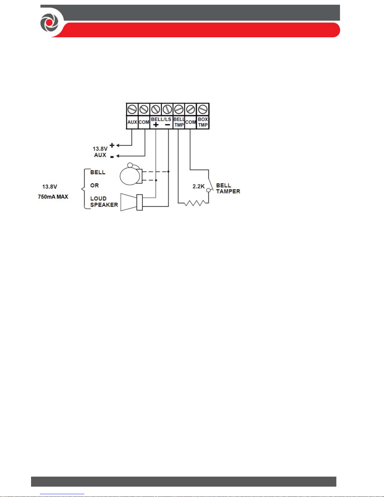
Connecting t he Bell / Loudspeaker
The Bell & LS (loudspeaker) terminals provide power to the internal bell (siren).
NOTE: A maximum of 750 mA may be drawn from this output.
To connect the internal bell (siren):
1. With main panel power removed, connect the internal bell with the correct
polarity (for installation instructions see the ProSYS Plus Installation and
Programming Manual and the packaged installation instructions).
2. At SW1 on the main panel PCB, be sure to position the BELL DIP switch
correctly accordingly (regarding bypassing or not bypassing the bell tamper).
See Setting Main Panel DIP Switches and Jumpers, page 11.
IMPORTANT: To avoid bell loop trouble, if no connections are made to an
internal bell, on the terminal block install a provided 2.2K resistor to the
BELL/LS (+ and – ) screw terminals, unless you are fitting an extension speaker
with DIP switch 1 in the OFF position.
Page 14
09/2016 Page 14 5IN2371 C
Connecting the Bel l Tamper
To utilize the bell tamper:
With main panel power removed, connect the bell tamper to the BELL TMP and
COM terminals on the main panel using a 2.2K resistor in serial.
BELL/LS (+): To connect to
the self activated bell’s
(SAB) positive hold off
input.
BELL/LS (—): To connect
to the SAB negative hold
off input.
BELL TMP: To connect to
the bell input of the SAB
Unit.
To not utilize the bell tamper:
If the installation does not utilize the main panel’s bell tamper, on the main
panel PCB set DIP switch 5 to ON to bypass the tamper protection. See Setting
Main Panel DIP Switches and Jumpers, page 11).
IMPORTANT: Even if you don’t utilize the bell tamper, connect a provided
2.2K resistor between the BELL TMP and COM terminals.
Connecting the Box Tamper (Wall Tamper)
The box tamper is pre-installed on the main panel housing (see box/enclosure
instructions).
To utilize the box tamper:
1. Connect back tamper wires to the BOX TMP terminals on the terminal block, or
alternatively connect via cable to the BOX TMP connection jack on the PCB.
NOTE: Do not wire the box tamper to both the terminal block and the PCB
connector simultaneously.
2. Set the box tamper DIP switch (DIP Switch 4) on main panel PCB to OFF (see
Setting Main Panel DIP Switches and Jumpers, page 11).
To not utilize the box tamper:
If not utilizing the main panel’s box tamper, to bypass the tamper protection
set DIP switch 4 on main panel PCB to ON (see Setting Main Panel DIP Switches
and Jumpers, page 11).
Page 15
09/2016 Page 15 5IN2371 C
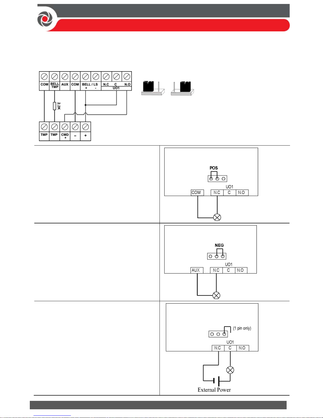
Connecting Utility Output 1
Utility outputs such as UO1 (Utility Output 1) are used to activate external
self-powered devices (such as siren):
Placing the JMP 2 (UO1) Jumper
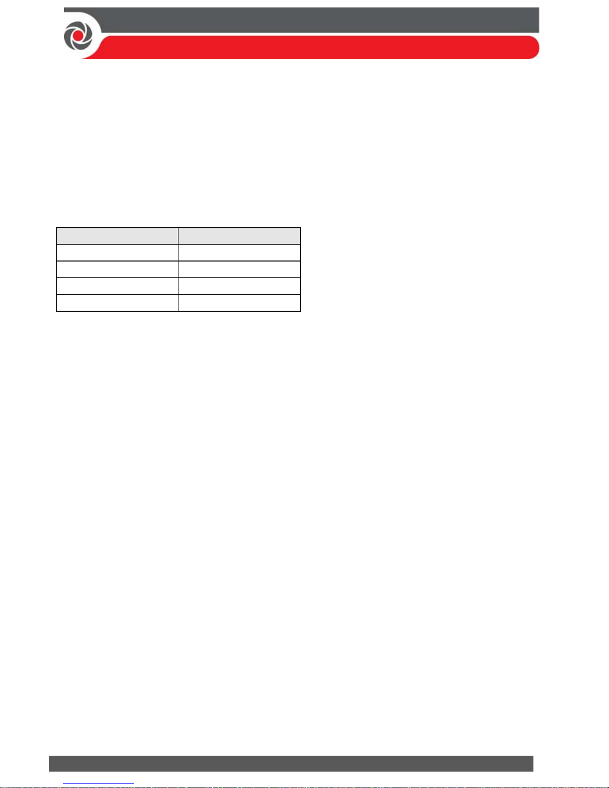
POS NEG
The JMP 2 jumper connector determines the
UO1 connection behavior. UO1 is normally use
d
for an external siren connection, as follows:
Positive (POS): When the JMP 2
jumper is placed on POS, the C
terminal on UO1 receives 13.8V.
NOTE: In this case, the maximum
combined current draw from the 2
AUX terminals plus UO1 and UO2 is
750m
Negative (NEG): When the JMP 2
jumper is placed on NEG, the C
terminal on UO1 receives COM.
If the JMP 2 jumper is placed only on
1 pin, the UO1 acts as a dry contact.
ProSYS Plus Main Panel
ProSYS Plus Main Panel
ProSYS Plus Main Panel
JMP 2
JMP 2
JMP 2
Page 16
09/2016 Page 16 5IN2371 C
Step 3: Bus Line Installations
ProSYS Plus supports up to 4 separate, independent RISCO bus lines. If one bus
line ever experiences a problem that interrupts data flow (such as being cut or
shorted), the other RISCO bus lines will continue operating normally.
Bus Line Wiring
On the main panel PCB, the 4 wires of each RISCO bus line (red, black, yellow,
green) connect to the respective screw terminals on the terminal block as follows:
Bus screw terminal Purpose
AUX RED +12 V DC power
COM BLK 0V common
BUS YEL Data (yellow wire)
BUS GRN Data (green wire)
Describing Bus Devices
All peripheral devices (bus detectors, keypads, sirens) as well as expansion modules
(Single-Zone Expanders, 8-Zone Expanders, 16-Zone Expanders, Wireless
Expanders, Power Supply Expanders, Bus Zone Expanders, Output Expanders) that
connect and communicate to the main panel via bus line are all referred to as
bus-connected devices, or “bus devices.” Bus devices fall under categories
pertaining to zones, outputs, power supplies, wired keypads and sirens.
NOTE: Even though zone expanders (single-zone, 8-zone, and 16-zone) connect
relay detectors and not bus detectors, they are bus devices.
Describing Bus Detectors and their Connection Options
Connect multiple bus detectors to RISCO bus lines via Bus Zone Expanders (BZEs),
which serve to expand the number of bus detectors and also enhance bus security
and performance. A smaller number of bus detectors can be connected individually
without connecting to Bus Zone Expanders – they are wired to a bus at the main
panel PCB (see Connecting Individual Bus Detectors to a Bus at the Main Panel,
page 21). For installation, refer to the packaged instructions supplied with the bus
detector.
Page 17
09/2016 Page 17 5IN2371 C
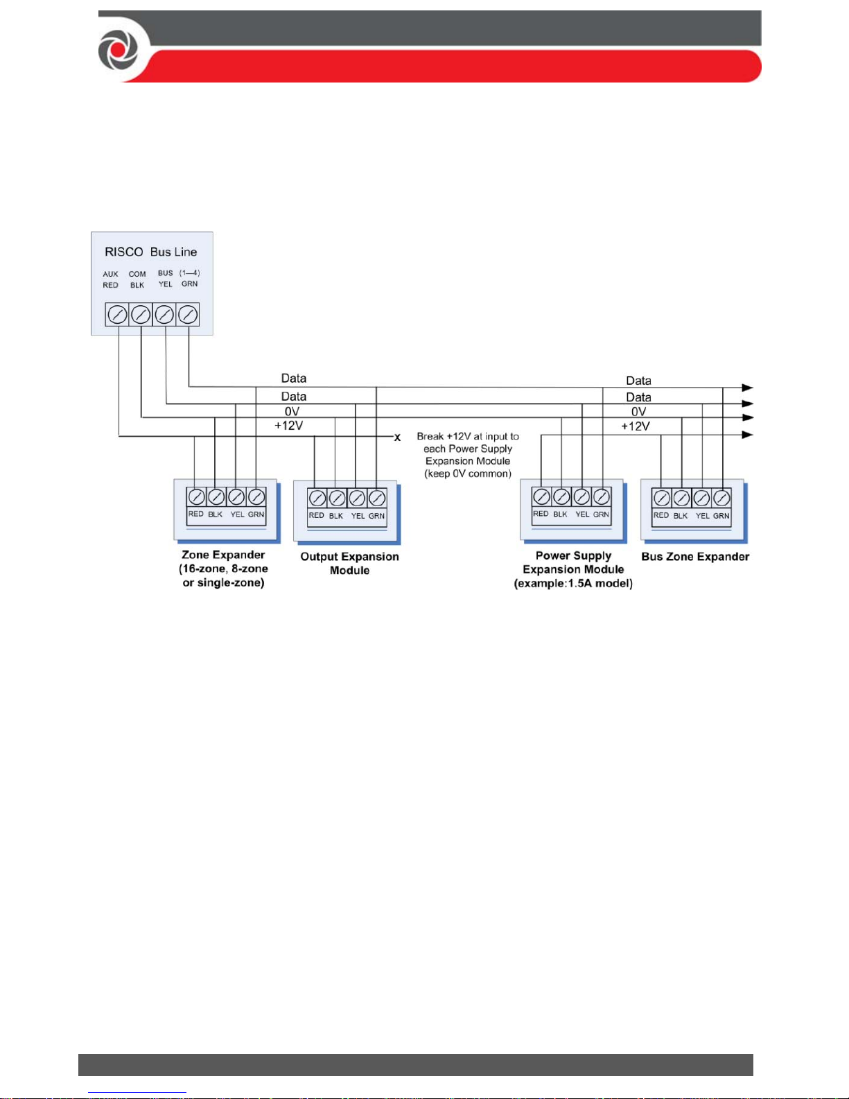
Wired Expansion Modules Installed on RISCO Bus Lines
The following shows different types of wired expansion modules typically
installed on a RISCO bus line (all are bus devices). Note that wireless expanders
can also be wired to a RISCO bus line.
NOTES:
The parallel wiring system supports parallel connections from any point along the
wiring.
Maximum wire run permitted is 300 meters (1000 feet) for each leg of a bus line.
In case of bus communication problems, connect two of the supplied 2.2K Ω
resistors, with one at each end of the bus data terminals (connecting the green
to the yellow terminals).
For long cable runs, please use the correct cable as stated in the Wiring Appendix of
the ProSYS Plus Installation and Programming Manual.
If connecting remote power supply units, do not connect the red wire (+12 V)
between the power supply unit and the ProSYS Plus main panel. Break the +12V
at the input to each power supply expansion module (keep 0V common).
If additional current is required on a bus line, install power supply expansion
module(s).
Page 18
09/2016 Page 18 5IN2371 C
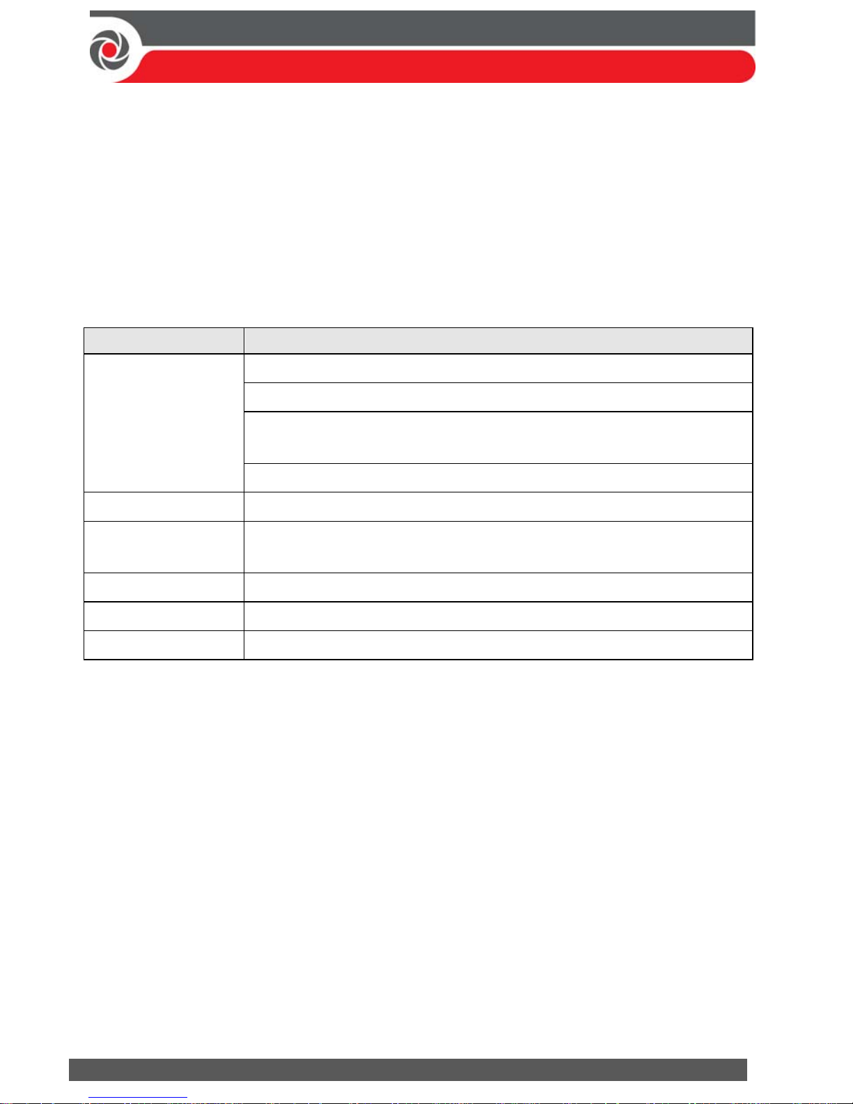
Describing Installer-Set ID Numbers for Bus Devices
For each bus device category (see table below), each of its respective bus devices
gets a sequentially-assigned, installer-set “physical” ID number that the installer
physically sets with the device’s DIP switches before powering up the device.
NOTE: To be unique, bus devices in the same category that are on the same bus
line must have sequentially different physical ID numbers, whereas different
devices (or the same bus device types on different bus lines) can have the same
physical ID number.
Categories Respective bus devices
ZONES
Bus Zone Expanders
Bus zones (bus detectors)
Zone expansion modules: Single-Zone Expander, 8-Zone
Expander, 16-Zone Expander
Wireless Expander
OUTPUTS Output expansion modules: (4 outputs/3A, 8 outputs/100 mA)
POWER SUPPLY
UNITS
Power supply expansion modules: 1.5A, 3A
WIRED KEYPADS Elegant, PS LCD, LS LCD
BUS SOUNDERS ProSound, Lumin8
KEY READERS Proximity Key Reader
Page 19
09/2016 Page 19 5IN2371 C
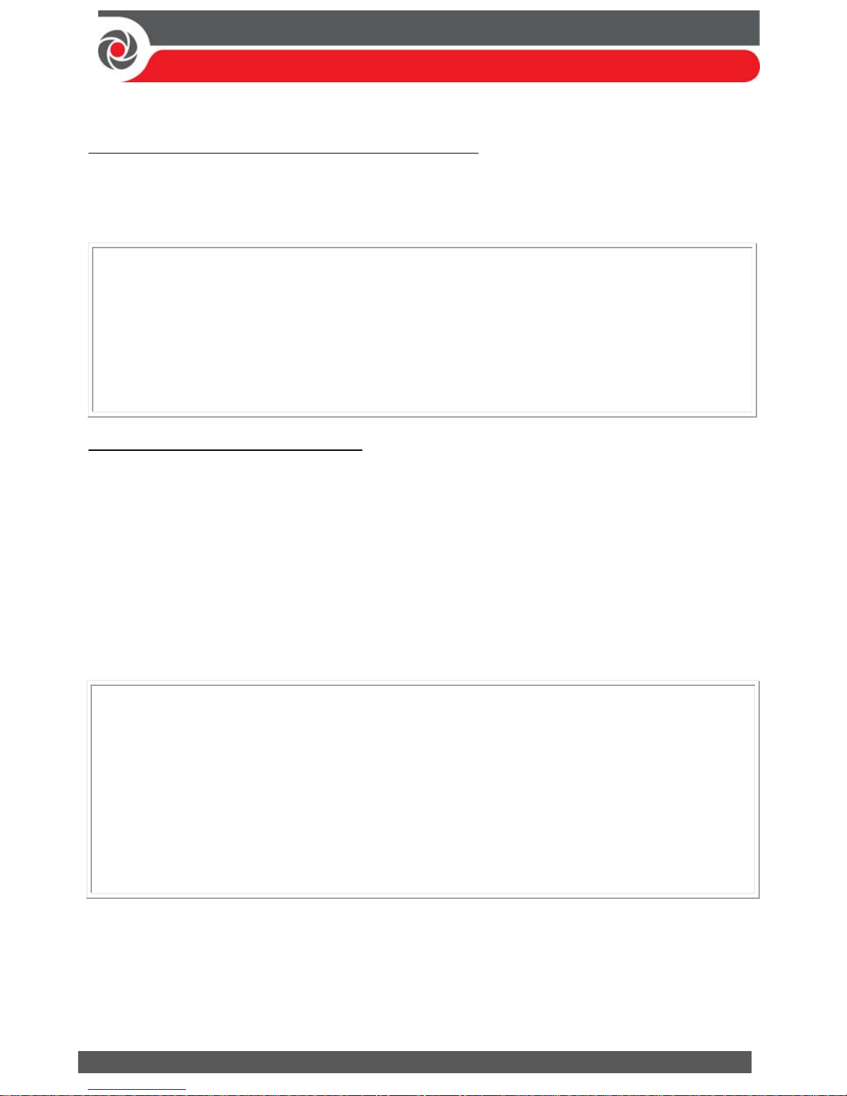
ID Number Formats
Keypads, sirens, as well as expansion modules (bus zone expanders, zone
expanders, wireless expansion modules, utility output modules, power-supply
expansion modules) that are connected via a RISCO bus line display on the keypad
as per this example: 02(1:01) T=NZE08
EXPLANATION:
02 is the index number of keypad, siren, or voice/expansion module
1 is the RISCO bus line number that it is on
01 is the sequential, installer-set physical ID number
T (type) is NZE08 (8-Zone Expander)
System detectors and accessories (other than keypads, sirens and expansion
modules) have their zones display as per these examples:
Bus detector connected via a bus zone expander: 4:B08:05
Relay detector wired to a zone expander: 4:E08:05, or wired to a zone (1—8)
on the terminal block: 4:E00:05
Input zone (relay detector wired directly onto a compatible type of bus device
(such as the iWISE Bus and Elegant keypad), which thereby shares its bus line
connection): 4:I08:05
Wireless detector connected to a wireless expansion module: 4:W08:05
EXPLANATION (for all 4 examples above):
4 is the RISCO bus line number
The next value (for B08, E08, I08, or W08) is for the ID of the expansion
module or input zone that the detector is connected to (B = bus zone
expander, W = wireless zone expander, I = input zone, E = wired zone
expander)
05 is the sequential, installer-set physical ID number
NOTES: [For main panel terminal block wiring]: For a bus zone expander wired
to a bus line at the terminal block, its ID will show as B00. For a relay detector
wired to a zone (1—8) at the terminal block, its ID will show as E00. For a UO
module wired to a UO terminal at the terminal block, its ID will show as 0x
(whereas x= zone number 1—6)
Page 20
09/2016 Page 20 5IN2371 C
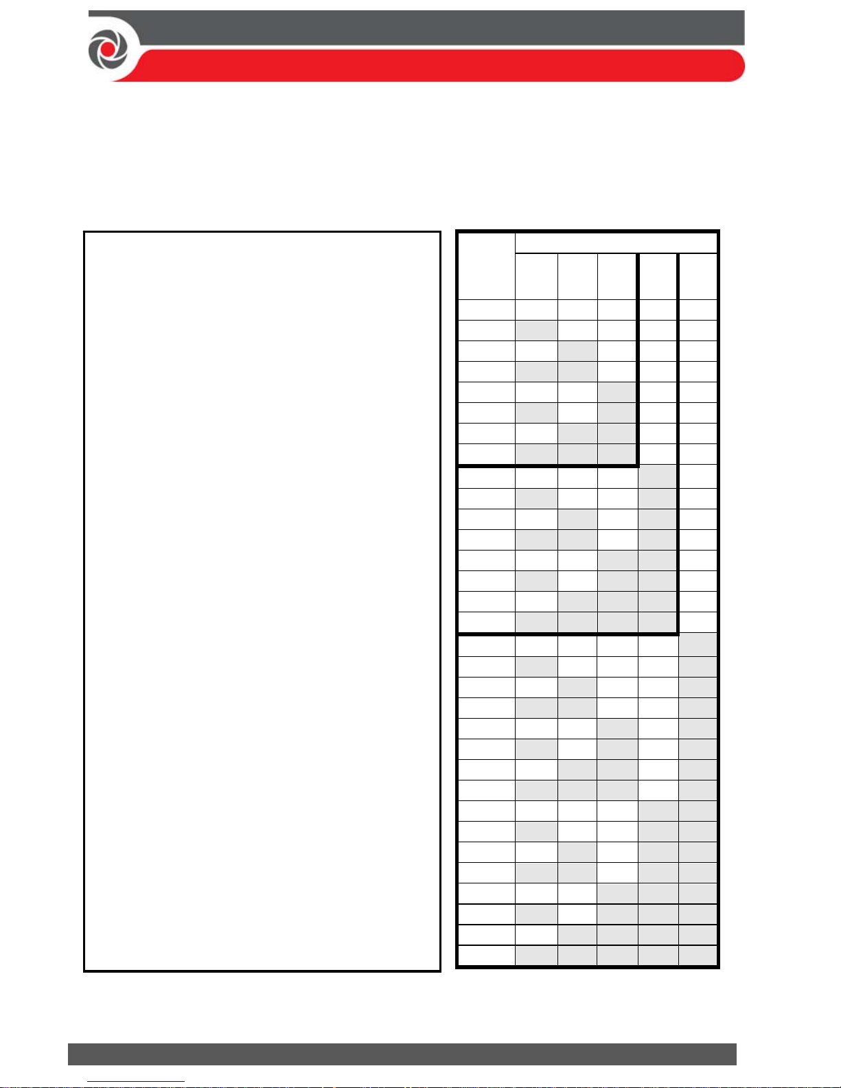
Assigning ID Numbers (Setting DIP Switches) for Bus Devices
When installing each bus device, you must set its DIP switches to match its
sequentially-assigned physical ID number before the device is powered up.
NOTE: If after power-up a device’s DIP switch(s) are changed, it will be necessary
to shut down the device’s power and then power it up again.
Bus
device
ID
DIP switches
12345
01 OFF OFF OFF OFF OFF
02 ON OFF OFF OFF OFF
03 OFF ON OFF OFF OFF
04 ON ON OFF OFF OFF
05 OFF OFF ON OFF OFF
06 ON OFF ON OFF OFF
07 OFF ON ON OFF OFF
08 ON ON ON OFF OFF
09 OFF OFF OFF ON OFF
10 ON OFF OFF ON OFF
11 OFF ON OFF ON OFF
12 ON ON OFF ON OFF
13 OFF OFF ON ON OFF
14 ON OFF ON ON OFF
15 OFF ON ON ON OFF
16 ON ON ON ON OFF
17 OFF OFF OFF OFF ON
18 ON OFF OFF OFF ON
19 OFF ON OFF OFF ON
20 ON ON OFF OFF ON
21 OFF OFF ON OFF ON
22 ON OFF ON OFF ON
23 OFF ON ON OFF ON
24 ON ON ON OFF ON
25 OFF OFF OFF ON ON
26 ON OFF OFF ON ON
27 OFF ON OFF ON ON
28 ON ON OFF ON ON
29 OFF OFF ON ON ON
30 ON OFF ON ON ON
31 OFF ON ON ON ON
32 ON ON ON ON ON
To set a bus device’s ID with its DIP
switches:
For each bus device, set its physical
ID number by placing its DIP
switches to ON or OFF according to
the table. Bus devices have between
3 and 5 DIP switches (check the
device’s packaged instructions for
details, as some bus devices may
have DIP switches that are not to be
used for setting the device ID).
NOTE: Categories of bus devices with 3 DIP
switches can be comprised of up to 8 IDs,
those with 4 DIP switches up to 16 IDs, and
those with 5 DIP switches up to 32 IDs. See
the following examples and the table:
EXAMPLE: For a bus device with 3 DIP
switches, to assign ID 02, DIP switch 1 needs
to be set to ON, and DIP switches 2 and 3
need to be set to OFF.
EXAMPLE: For a bus device with 4 DIP
switches, to assign ID 04, DIP switches 1 and
2 need to be set to ON, and switches 3 and 4
need to be OFF.
EXAMPLE: For a bus device with 5 DIP
switches, to assign ID 07, DIP switch 1 needs
to be set to OFF, DIP switches 2 and 3 need
to be ON, and DIP switches 4 and 5 need to
be OFF.
Page 21
09/2016 Page 21 5IN2371 C
Installing Bus Devices
When installing bus devices, in addition to the guidelines presented in this manual,
see their packaged installation instructions. For installing Power Supply Expansion
modules, Utility Output Expansion modules, Wireless Expanders, Bus Sirens, and
Zone Expanders, also see the ProSYS Plus Installation and Programming Manual.
Installing Wired Keypads
Connect wired keypads to a bus line, or to a bus at the main panel terminal block.
A wired keypad is the first device to be installed, as it is used to set defaults upon
initial system power-up (language, time and date), to perform an Auto-Setting scan
(for allocating bus-connected devices), and to configure parameters.
To install a wired keypad
1. Ensure the main panel is powered off.
2. Ensure DIP switch 2 on the main panel PCB is set to ON. This enables you to set
the defaults (language, time & date) upon system initialization. See Setting Main
Panel DIP Switches and Jumpers, page 11.
3. Set the keypad’s DIP switches (see Describing Installer-Set ID Numbers for Bus
Devices, page 18) according to the instructions packaged with the keypad.
4. Set the keypad’s back tamper switch (see keypad instructions).
5. Wire the keypad to a RISCO bus line, or to a bus on at the main panel terminal
block (see Main Panel Wiring Diagram, page 10).
6. Refer to the keypad instructions for additional installation information.
Connecting Indi vidual Bus Detectors to a Bus at the Main Panel
To connect bus detectors individually on a bus at the main panel PCB:
1. Remove system power.
2. Connect each bus detector to the bus line per its packaged instructions.
3. Sequentially assign each bus detector’s ID (01—32) and set it accordingly with
its 5 DIP switches. See Assigning ID Numbers (Setting DIP Switches) for Bus
Devices, page 20.
NOTE: For WatchOUT, LuNAR, WatchIN, BWare and Seismic set the switch
that defines the detector’s operational mode to bus mode.
4. Connect the 4 bus wires to their respective bus screw terminals on the main
panel PCB (terminal block): AUX (RED), COM (BLK), BUS (YEL), BUS (GRN).
NOTE: For maximum operation stability, bus line wiring from any bus
detector to the main panel should not exceed a total 300 meters (1000 feet).
NOTE: For testing the bus, see Performing a Bus Test, page 31.
Page 22
09/2016 Page 22 5IN2371 C
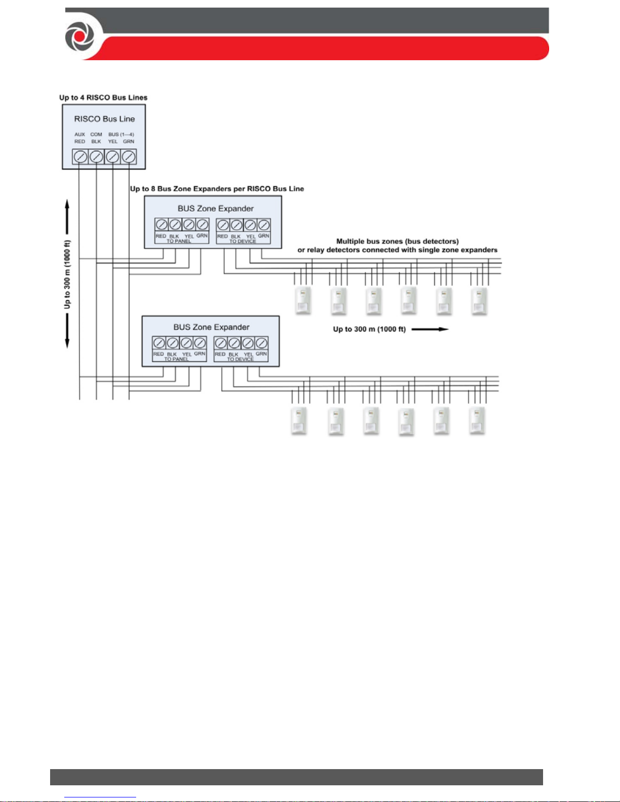
Connecting Multiple Bus Det ectors using B us Zone Expanders
To connect multiple bus detectors to bus lines using bus zone expander(s):
1. Remove system power.
2. At SW1 on the BZE (bus zone expander), use DIP switches 1—3 to sequentially
set the BZE’s physical ID number. Note that DIP switch 4 is not used.
3. At SW2 on the BZE set DIP switch 3 to ON.
4. At SW2 on the BZE, set DIP switch 4 to OFF to utilize the tamper switch, or set
it to ON to disable the tamper.
5. Wire the bus line to the BZE terminals marked TO PANEL.
6. Set each bus detector’s physical ID number sequentially, using each detector's
DIP switches. NOTE: Do not assign the same physical ID number to more than
one detector on the same BZE.
7. Wire each bus detector's terminals to the relevant BZE terminals marked
TO DEVICE.
NOTE: For maximum operation stability, do not exceed 300 meters (1000 feet)
of wiring from any BZE to the main panel and do not exceed 300 meters (1000
feet) of wiring from any BZE to the farthest detector it supports.
NOTE: For testing the bus, see Performing a Bus Test, page 31.
Page 23
09/2016 Page 23 5IN2371 C
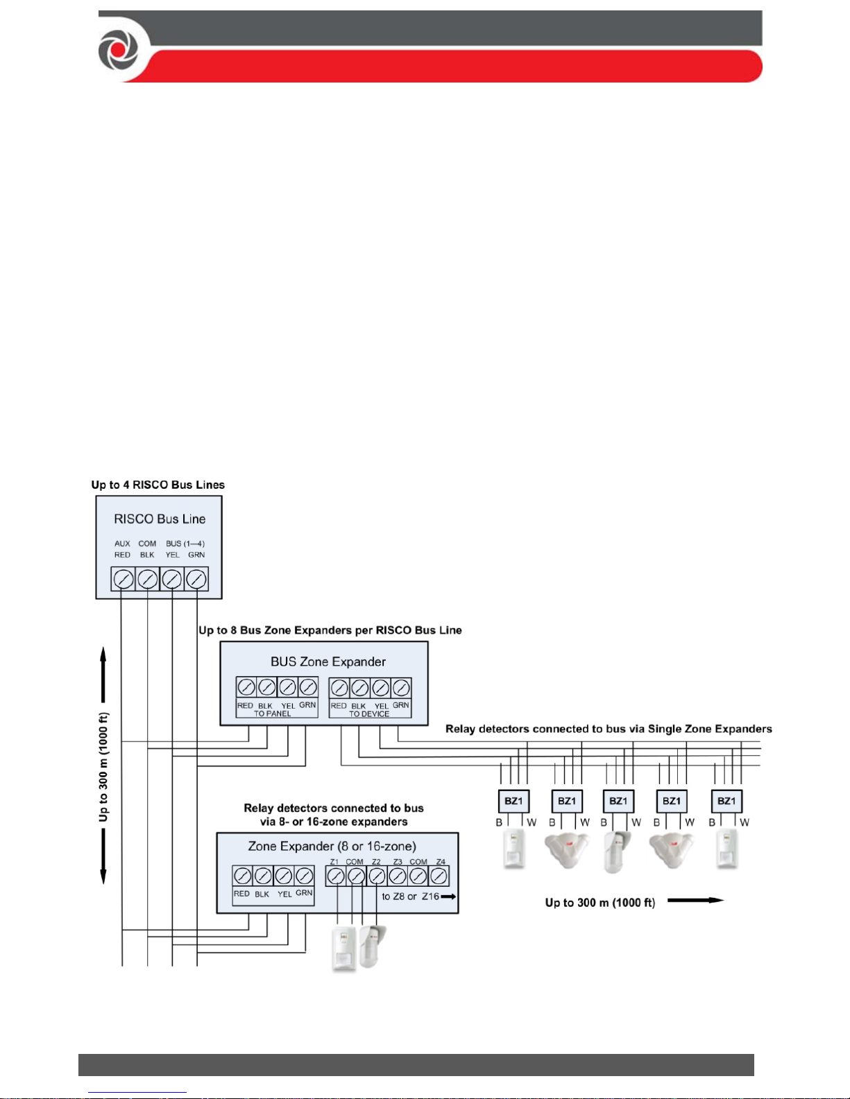
Step 4: Connecting Relay Detectors
Wired non-bus detectors (“relay detectors”) can be connected to the system the
following ways:
Refer the ProSYS Plus Installation and Programming Manual and the installation
instructions for the relay detectors and for zone expanders.
Connect relay detector(s) directly at the zone input terminals (Z1—Z8) on the
terminal block of the main panel PCB. See Main Panel Wiring Diagram, page 10.
Connect multiple relay detectors onto 8-Zone Expanders and 16-Zone Expanders.
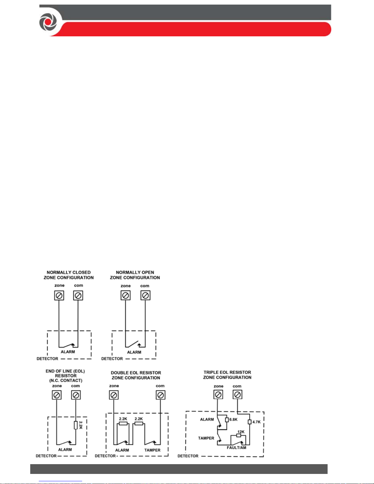
Connect relay detector(s) onto RISCO bus lines, each using a dedicated Single Zone
Expander (see illustration, below).
Connect a single relay detector directly onto bus devices which support an input
zone. For the Elegant keypad, connect a relay detector to ZONE IN and ZONE
COM terminals, and for the iWISE Bus detector connect to Z1 and COM terminals.
Page 24
09/2016 Page 24 5IN2371 C
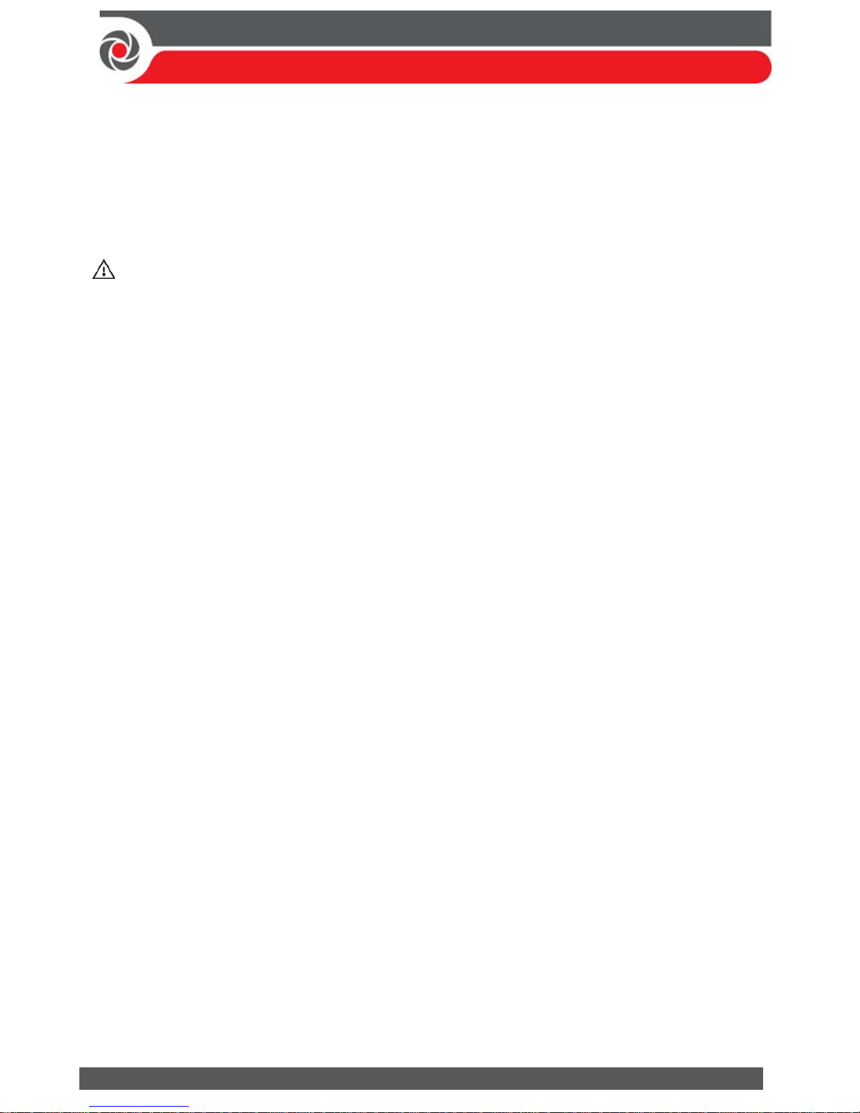
Defining Zone Termination Resistance
End-of-line termination resistance can be defined for relay detectors, not wireless
or bus detectors. Defining the end-of-line resistance involves first physically wiring
resistors (if not already in place) at installation, and then afterwards selecting the
zone’s termination resistance option at the keypad during installer programming
(see Defining Zone Termination Resistance using the “Resistance” Option, page 43).
NOTE: For relay detectors wired to zone expanders, during installer programming
you separately define their individual termination resistance values, and also define
it for the zone expanders.
Wiring Resistors for Zone Termination Resist anc e
To wire termination resistors:
For RISCO EOL (end-of-line) and DEOL (double-end-of-line) detectors without
built-in termination resistance, install a 2.2K Ω end-of-line resistor at the
detector-side of each hard-wired zone
For a detector with a tamper switch, you can use DEOL termination to save
additional main panel connections
For RISCO TEOL (triple-end-of-line) detectors without built-in end-of-line resistance,
install 4.7K Ω, 6.8K Ω and 12K Ω resistors at the detector-side of each hard-wired
zone. TEOL is supported to identify detector masking and trouble.
Zone Termination Configur at ion Options
Page 25
09/2016 Page 25 5IN2371 C
Step 5: Connecting the Backup Battery and Mounting
the Main Panel
Connecting the Backup Battery
The main panel backup battery is not supplied with the system. Inside the main
panel box/enclosure, install a rechargeable battery, up to 21 Ah, 12 V.
WARNINGS:
To avoid damaging system components, do not connect the backup battery
until all installation tasks are completed, and the system is ready for initial
power-up.
The backup battery must be replaced about every 3—5 years.
There is a risk of explosion if a battery is replaced with an incorrect type.
Dispose of used batteries per applicable law and regulation.
Battery charging takes at least 24 hours before it can be fully used for backup
To connect the main panel’s backup battery:
1. First ensure that DIP switches and jumpers have been set appropriately so that
you can program the system parameters (see Setting Main Panel DIP Switches and
Jumpers, page 11).
a. At SW1 on the main panel PCB, set DIP switch 2 to ON. This allows
language selection at first-time system power-up.
b. To bypass unused box and bell tampers (to prevent tamper alarms), at SW1
set box tamper and bell tamper DIP switches (4 and 5 respectively) to ON.
c. You can configure battery discharge protection with the Non Protect
jumper (see the ProSYS Plus Installation and Programming Manual).
2. Now connect the leads of the battery cable to the respective (+) and (–) terminals
on the backup battery with correct polarity. Then insert the battery in place in
the main panel housing (see box/enclosure instructions) and attach the cable to
the battery connector on the panel PCB (Main Panel Wiring Diagram, page 10).
Mounting the Main Panel
To mount the main panel:
1. Close up the box/enclosure and then mount it to the wall. See instructions
packaged with the box/enclosure, the ProSYS Plus Installation and Programming
Manual, as well as Step 1: Creating a Plan for Mounting the System, page 8.
2. You are now ready for powering-up the system and system initialization tasks.
Page 26
09/2016 Page 26 5IN2371 C
System Initialization, Device Allocation, General
System Configuration
For installer programming using the Configuration Software, see its documentation.
Step 1: Working with the Keypad and Installer Menus
Describing Dynamic Keypad Menus
The ProSYS Plus installer menus and user menu are dynamic, in that they display
menu items according to the devices connected in the system.
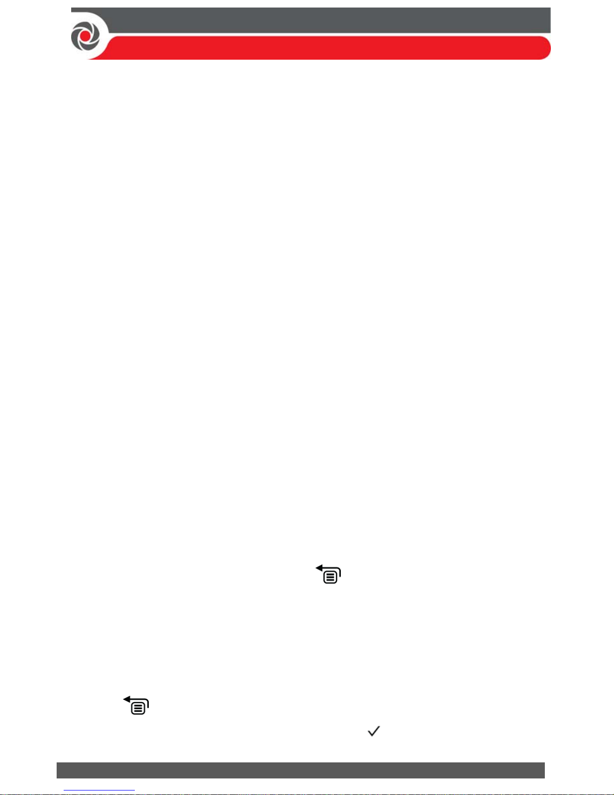
Table of Menu Navigatio nal Key s
The following describes the typical Elegant keypad keys used for programming:
NOTE: Other keypad buttons may differ – see their packaged instructions.
Key Description
1—0
For entering codes, using quick keys (to quickly access a menu
option, labels, and for entering other numeric values.
To go back a step in the menu, to exit a menu or return to the
b
eginning of a menu.
Long-press to get system status
Confirm (after entering) / OK / Save
For scrolling through menus and menu options, and for toggling,
such as between “ON” and “OFF” options.
To toggle between options
A, B, C, D Used to select a group
Designating Labels
The following table describes all the available characters at the Elegant keypad.
Key Character Options Key Character Options
1 1 . , ‘ ? ! \ “ — < > @ / : _ + * #
7
7 P Q R S
2 2 A B C 8 8 T U V
3 3 D E F 9 9 W X Y Z
4 4 G H I 0 0 (also use for blank space)
5 5 J K L A
To toggle between lower case and
capital letter
6 6 M N O
To scroll through all possible characters,
to toggle through options (Yes/No)
Page 27
09/2016 Page 27 5IN2371 C
Entering the Installer Programming Menu at Initial System Setup
After initial system power-up, language, time and date setting, viewing enabled
zones and defining system partitions, you’ll be in the installer Programming menu,
at Auto Settings.
IMPORTANT: After you finish initial system setup programming tasks from the
installer Programming menu, in order to exit you must perform the procedure for
Step 2: Exiting Installer Programming Menu after Initial System Configuration, page 52.
Subsequently Accessing Installer Menus
After exiting the installer Programming menu (after you finished programming in
it the first time), if you subsequently ever want to access this menu again (or to
access other installer menus, such as the installer Maintenance menu for testing),
make sure you set DIP switch 2 to OFF, otherwise it will reset the installer,
sub-installer and Grand Master codes to factory defaults. If you want to program
from the installer Programming menu again, another option is to do so from the
Configuration Software.
Step 2: Powering-Up and Initializing the System
When a new system is powered-up the first time, here are the initialization steps:
1: Initial power-up & language selection. The system automatically connects to the
Cloud.
2: View enabled zones, define the maximum number of system partitions, and set
the time & date.
Initial System Power-Up and Language Selection
NOTE: During regular system operation (after initial system setup) the language
can be subsequently changed by pressing + 9 simultaneously.
To initially power-up and select a language:
1. Power-up the main panel; the keypad panel takes a few seconds to initialize
(there may be an automatic 3-minute upgrade that runs automatically, during
which the upgrade and power icons may display on the keypad – make sure
you do not disconnect).
2. Press when prompted.
3. Scroll to select a language, and then press OK ( ).
Page 28
09/2016 Page 28 5IN2371 C
Viewing Zones, Defining Partitions, and Setting the Time & Date
You can now view enabled zones (the default of 64 zones, or the total number of
enabled zones which includes any additional zone licenses purchased via the RISCO
Store and activated using HandyApp), select the maximum number of partitions,
and set the time & date.
NOTE: You can opt to define the maximum partitions at a later stage – from the
keypad (during installer programming), or from the Configuration Software.
NOTE: To add additional zone licenses after system initialization, see Viewing &
Updating Zones and Defining Partitions after Initialization, page 29.
Viewing Zones, Defining Partitions, and Setting Time/Date at Initialization
To view enabled zones, define partitions, and set time/date at system
initialization:
1. When prompted, enter the installer code (default is 1111), then press OK ( ).
If you don’t enter the code within 10 seconds, wait a few seconds for the keypad
to restart;
If the panel configuration is Cloud-compatible (IP/GSM module/s are
installed), then CLOUD CONNECTING displays as the panel tries to connect to
the Cloud. If there is trouble connecting, CONNECTION TROUBLE. RETRY?
will display – in this case, check parameters and perform diagnostics (see the
ProSYS Plus Installation and Programming Manual section on Troubleshooting) and
then select Y (yes) to try again to reconnect or press N (no).
-OR-
If the panel configuration is not Cloud-compatible (IP/GSM module/s are not
installed), then 064 ZONES ENABLED displays (the default number of zones).
2. Press ; upon successful Cloud connection, if new zone licenses (above the 64
supplied) have been purchased, they will display. If no new zone licenses were
purchased, the default 064 Zones Enabled displays.
3. Press ; PARTITION QUAN 08 (08—32) displays.
4. Enter the maximum number of partitions you want in the system – the default is
08 (meaning up to 8); but up to 32 can be selected. If you want more than 8
partitions, enter the number. Now press ; ENTER TIME/DATE displays.
5. Enter the time and date, and then press ; BUS DEVICE: 1) AUTOMATIC
displays, indicating you are now in the installer Programming menu, and ready
to perform an Auto Settings scan (see Step 3: Allocating and Configuring Installed
Components, page 30).
Page 29
09/2016 Page 29 5IN2371 C
Viewing & Updating Zon es and Defining Par t itions after Initialization
After system initialization, you can view the total number of enabled zones, define
partitions, and also manually update the system with any additional zone licenses
purchased via the RISCO Store and activated using HandyApp -- this can be
useful, for example, if during system initialization the automatic connection to the
Cloud fails.
To view enabled zones after system initialization:
1. Enter your installer code (default is 1111).
2. From the installer Programming menu, go to: 1 > 5 > 7 (System > Settings >
Licenses), and then press OK ( ).
3. Scroll to 1) View Licenses to view the total number of enabled zones (the default
of 64 zones plus any additional zone licenses purchased via the RISCO Store
and activated using HandyApp), and then press .
NOTE: The panel must be connected to the Cloud in order to display the total
number of enabled zones, otherwise only the default number (64 provided
zones) will display.
To update the system with new zone licenses after system initialization:
To manually update the system with the new zone license information (for any
new zone licenses that were purchased via the RISCO Store and activated using
HandyApp), scroll to 2) D/L Licenses and then configure the Cloud-connectivity
parameters.
To define the partition quantity after system initialization:
1. Go to: 1 > 5 > 8 (System > Settings > Partition Qty, and then press ;
MAXIMUM PARTITIONS? 08 (08—32) displays.
2. Enter the maximum number of partitions to enable in the system – the default is
08 (meaning up to 8), but up to 32 can be selected. If you want more than 8
partitions, enter the number. Now press .
Page 30
09/2016 Page 30 5IN2371 C
Step 3: Allocating and Configuring Installe d
Components
Allocate and configure all installed communication/expansion modules and bus
devices via Auto Setting.
Auto-Setting Allocation of Communication Modules and Bus
Devices
Performing an Auto-Setting scan finds all installed communication modules and
bus devices connected in the system. As you view the results, you allocate
(“enable”) each, and then you can configure their settings – either now, or later
during installer programming (for configuration details see Manually Allocating &
Configuring Communication Modules, page 32, and Manually Allocating & Configuring
other Modules and Bus Devices, page 34).
To perform an Auto-Setting system scan:
1. Upon accessing the installer Programming mode after system initialization,
when BUS Device: 1)Automatic displays (Auto Settings feature), press OK
( ); BUS SCANNING displays during scanning, until the results display - the
communication modules first, followed by the other bus devices that are found.
For a description of the results, see Describing Auto-Setting Results, page 31.
2. Press to enable the first communication module displayed, and keep
pressing to progress through its parameter configuration screens (which you
can configure now, or later during installer programming).
3. Press again to advance to the next communication module (if applicable) –
followed by all other bus devices found, and again enable/configure for each.
4. Make sure all the communication modules/bus devices found in the scan match
all the communication modules/bus devices physically connected in the system.
When BUS Device: 1)Automatic displays again and the panel beeps, it indicates
you have finished the Auto-Setting scan.
5. Now you can perform a Bus Test to ensure good communication between the
allocated bus devices and the main panel (see Performing a Bus Test, page 31).
NOTE: If you subsequently add more bus devices, you can either allocate and
configure them manually, or repeat an Auto-Setting scan at:
installer Programming menu > 7)Install > 1)BUS Device > BUS Device: 1)Automatic
Page 31
09/2016 Page 31 5IN2371 C
Describing Auto-Setting Results
At the keypad, the results of an Auto-Setting scan first show the connected
communication modules. The next results displayed are for connected
keypads, expansion/voice modules and bus detectors. Results display as per
this example: (3:02:01) T=LCD
EXPLANATION:
NOTE: Dashes (—) appear instead of digits when a parameter is not relevant,
for example, for communication modules (since they are “on-board” on the
PCB, and not on a bus line).
3 is the bus line it is connected to
02 is the expander ID
01 is its sequential, installer-set physical ID number for bus devices (see
Describing Installer-Set ID Numbers for Bus Devices, page 18). Note that
communication modules will always appear as 01.
T is the type, which, in this example is LCD keypad
Performing a Bus Test
A Bus Test checks each installed bus device and communication module to ensure
adequate connectivity quality.
A result of 97% or less than may mean that there are bus connection problems.
To perform a Bus Test:
1. From the installer Programming menu, go to: 7 > 1 > 3 > 1 (Install >
Bus Device > Testing > Bus Test); BUS TEST displays for a few seconds until
the BUS COM QUALITY results display.
2. Scroll to view the results for each bus device/module on the tested bus. If a
result is not adequate, check physical connections and DIP switch positions, and
then repeat the test. Results display as per this example: GSM :001 =100%
EXPLANATION:
GSM is the communication module/bus device description
001 is the communication module/bus device index number
100% is the result
Page 32
09/2016 Page 32 5IN2371 C
Manually Allocating & Configuring Communication Modules
If you didn’t yet run an Auto-Setting scan to allocate (“enable”) each installed
communication module, from the installer Programming menu, you can do so
manually, as well as configure its relevant parameters.
IMPORTANT: If an allocated communication module is no longer to be utilized,
you must disable it (cancel its allocation) via this manual process. After cancelling,
if needed, you can then re-write over it to newly allocate another communication
module.
NOTE: After manually programming communication modules, you can perform a
Bus Test (see Performing a Bus Test, page 31).
GSM Modules
1. From the installer Programming menu select 7> 1> 2, scroll to 10) GSM, and
then press OK ().
2. Press to toggle to the type of GSM module installed (or select NONE to
cancel its allocation), and then press .
Entering or Deleting a SIM Card PIN
If your SIM card requires a PIN (personal ID number) you will need to enter it. If
not, you will need to disable it.
To enter or delete a SIM card PIN:
1. From the installer Programming menu select 5 > 1 > 2 > 5 > 1, enter the PIN,
and then press OK ( ).
-OR-
If a PIN is not needed, you can choose to disable it by inserting the SIM card in
a cell phone and disabling the code.
2. You can manually define APN definitions if you don’t have them configured
automatically (the default). See Defining APN Automatically and Manually,
page 33.
NOTE: It is recommended to test the operation of a SIM card by conducting a
call and testing the GSM signal strength. See Testing the System, page 53.
Page 33
09/2016 Page 33 5IN2371 C
Defining APN Automatically and Manually
After the SIM card is installed and upon establishing GSM/GPRS communication,
the system’s auto-APN feature will automatically configure the APN definitions.
However, there may be cases where you will need to manually define the APN by
entering the APN (Access Point Name) code supplied from the cellular provider,
user name, and password.
NOTE: If any of the APN definition fields are populated manually, the auto-APN
feature will not operate.
To manually set the APN definitions:
1. From the installer Programming menu, select: 5 > 1 > 2 > 2 > 1
(Communication > Method > GSM > GPRS > APN code), then press OK ().
2. Enter the APN code, and then press .
3. Scroll to 2) APN User Name, press , enter the user name, and press .
4. Scroll to 3) APN Password, press , enter the password, and press .
IP Modules
1. From the installer Programming menu select 7> 1> 2, scroll to 11) IP, and then
press OK ().
2. Press to toggle to the type of IP module installed (or select NONE to
cancel its allocation), and then press .
Setting Dynamic IP / Static IP
Go to: 5 > 1 > 3 > 1 > 1, scroll to either 1) Dynamic IP or 2) Static IP, then press .
PSTN Modem Module
1. From the installer Programming menu, select 7> 1> 2, scroll to 12) Modem, and
then press OK ().
2. Press to toggle to Modm (or select NONE to cancel its selection), then
press .
Long-Range Radio Tran sm itter Module
See the ProSYS Plus Installation and Programming Manual and the LRT module’s
instructions.
1. From the installer Programming menu select 7> 1> 2, scroll to 14) LRT, and
then press OK ().
2. Press to toggle to the type of LRT module installed (or select NONE to
cancel its allocation), and then press .
Page 34
09/2016 Page 34 5IN2371 C
Manually Allocating & Configuring other Modules and Bus
Devices
If you didn’t yet run an Auto-Setting scan to allocate (enable) all the installed
non-communication modules (for example, expansion modules) or other bus
devices – or if you are adding new ones and don’t want to perform an Auto-Setting
scan of the entire system, instead you can allocate them manually. Also, if you
didn’t configure parameters during the Auto-Setting scan, you can do so now.
IMPORTANT: If no longer utilizing a previously allocated module/bus device,
you’ll need to manually cancel its allocation. After cancelling, if needed, you can
then re-write over it (to newly allocate) another module/bus device.
NOTE: After manually programming other modules and bus devices, you can
perform a Bus Test to ensure good communication between the bus devices and
the main panel (see Performing a Bus Test, page 31).
Wired Keypads
1. From the installer Programming menu, select 7> 1> 2, then scroll to
01)Keypad and press OK ( ).
2. Scroll to, and then edit the keypad’s physical ID number to match its DIP switch
settings (see Describing Installer-Set ID Numbers for Bus Devices, page 18).
3. Press to toggle to the correct keypad type (or select NONE to cancel its
allocation), and then press ; Assign to Partition displays.
4. Scroll to manually edit (type in) the partition number or press to toggle to
the correct partition number, and then press ; the Mask screen displays where
you enable operability of specific partition(s) with this keypad. By default, for
keypad 01 all partitions are enabled.
5. While scrolling through each block of partitions, designate the partition(s) to
allow operation via the keypad. Enter a partition number to select it (it will
display), or enter the number again to clear it (it will not display). Then
press ; Controls / 1) Emergency displays.
6. Scroll to Control parameters and press to enable/disable (Y/N) as needed:
1)Emergency – to operate the emergency quick keys at the keypad.
2)Multi View – to view from this keypad the status of all masked
partitions (select Y) or only the partitions (select N).
3) Exit beeps – (for a 2-Way wireless Slim keypad with bypass)— sounds
beeps during the exit time in stay arming.
4)Supervision – to enable (Y) or disable (N) supervision for a wireless keypad.
7. Press to go to the next keypad, and repeat this procedure from step 2.
Page 35
09/2016 Page 35 5IN2371 C
Zone Expander s
1. From the installer Programming menu, select 7> 1> 2, scroll to 02) Zone
Expand., and then press OK ().
2. Scroll to, and then edit the zone expander’s physical ID number to match its DIP
switch settings (Describing Installer-Set ID Numbers for Bus Devices, page 18).
3. Press to toggle to the type (NZE08 for an 8-zone expander, or NZE16 for a
16-zone expander), or select NONE to cancel its allocation, then press .
4. Select the zone termination resistance if applicable by scrolling to the correct
resistor values (in ohms), then press to advance to the next zone expander.
5. Repeat from step 2 for all additional zone expanders.
Utility Output Modules
1. From the installer Programming menu, select 7> 1> 2, scroll to 03) Util. Output,
and then press OK ().
2. Scroll to, and then edit the module’s physical ID number to match its DIP switch
settings (see Describing Installer-Set ID Numbers for Bus Devices, page 18).
3. Press to toggle to the UO type (or select NONE to cancel its allocation),
and then press .
Power Supply Modul es
1. From the installer Programming menu, select 7> 1> 2, scroll to
04)Power Supply, and then press OK ( ).
2. Scroll to, and then edit the PS module’s physical ID number to match its DIP
switch settings (see Describing Installer-Set ID Numbers for Bus Devices, page 18).
3. Press to toggle to the PS type (or select NONE to cancel its allocation), and
then press .
4. Select the partition number(s) for the power supply module. While scrolling
through each block of partitions, designate the partition(s) to allow operation
via the keypad. Enter a partition number to select it (it will display), or enter the
number again to clear it (it will not display).
5. Press ; 1)BELL/L.SPEAK N displays
6. Press to toggle between Y (yes) or N (no) for enabling or disabling the
bell / loudspeaker, and then press .
7. Repeat from step 2 for all additional power supply modules.
Page 36
09/2016 Page 36 5IN2371 C
Wireless Expanders
1. From the installer Programming menu, select 7> 1> 2, scroll to
05)WL Expander, and then press OK ().
2. Scroll to, and then edit the WL expander’s physical ID number to match its DIP
switch settings (see Describing Installer-Set ID Numbers for Bus Devices, page 18).
3. Press to toggle to WM (wireless module), or select NONE to cancel its
allocation, and then press .
4. Press to toggle to Y or N for the bypassing box tamper, then press .
Proximity Key Readers
1. From the installer Programming menu, select 7> 1> 2, scroll to 06)Prox Key Rd,
and then press OK ( ).
2. Scroll to, and then edit the PRK’s physical ID number to match its DIP switch
settings (see Describing Installer-Set ID Numbers for Bus Devices, page 18).
3. Press to toggle to PRK (Proximity Key Reader) or select NONE to cancel
its allocation, and then press ; the Mask screen displays where you can enable
operability of specific partition(s) when using this PKR.
4. While scrolling through each block of partitions, designate the partition(s) to
allow operation via the PKR. Enter a partition number to select it (it will
display), or enter the number again to clear it (will not display), then press .
5. Scroll through the various “Controls” options and toggle between Y and N for
each using , and then press .
6. Repeat this procedure from step 2 for all additional PKRs.
Voice Module
The ProSYS Plus supports 1 voice module.
1. From the installer Programming menu, select 7> 1> 2, scroll to
07)Voice Module, and then press OK ( ).
2. Press to toggle to T=Voice (the Voice Module), or select NONE to cancel
its allocation), and then press .
3. Enter the 2-digit R. Phone Code (remote phone code), and then press .
4. Scroll to select a language for voice announcements, and then press .
Page 37
09/2016 Page 37 5IN2371 C
Sounders (Si r ens)
1. From the installer Programming menu, select 7> 1> 2, scroll to 08)Sounder, and
then press OK ().
2. Scroll to, and then edit the sounder’s physical ID number to match its DIP
switch settings (see Describing Installer-Set ID Numbers for Bus Devices, page 18).
3. Press to toggle to the type (or select NONE to cancel its allocation), and
then press .
4. Select the partition number(s) for the sounder. While scrolling through each
block of partitions, designate the partition(s) to allow operation via the keypad.
Enter a partition number to select it (it will display), or enter the number again
to clear it (it will not display).
5. Scroll to and select the partition number for the siren, and then press .
6. Select Y to enable the sound (or use to toggle to N), and then press .
7. Select Y or N for squawk sound, and then press .
8. Select Y or N for squawk strobe, and then press .
9. Repeat from step 2 for all additional sirens.
Bus Zones (Bus Detectors)
1. From the installer Programming menu, go to: 7>1>2>0>9 (Install > Bus Device >
Manual, and scroll to 09)Bus Zone) and then press OK ( ); the first available
(non-allocated) bus zone displays as per this example. Note that the empty
fields in the parenthesis indicate that the zone has not yet been allocated:
Select (-:- -- :- -)
017) ZONE 017
2. Scroll to the zone that you want to allocate the bus zone to, then press OK ( );
the following (example) displays:
BUS ZONE: (017)
(1:00:01) T=xxxx)
EXPLANATION:
1 is the bus line number
00 is the bus zone expander ID (1—32) that the bus detector is
connected to (00 means wired to a bus line at the main panel PCB)
01 is the installer-set physical ID number for the bus detector
T is the type (description).
Page 38
09/2016 Page 38 5IN2371 C
3. Scroll to and then edit the bus detector’s physical ID number to match its DIP
switch settings (see Describing Installer-Set ID Numbers for Bus Devices, page 18).
4. Press to toggle to the correct bus zone type (or select NONE to cancel its
allocation), and then press ; “Link Bus Input to Zone ###?” displays (whereas
### is the zone number).
5. To link (enable), use to toggle to Y, and then press .
6. Repeat this procedure for all additional bus detectors.
Bus Zone Expanders
1. From installer Programming menu, go to: 7>1>2>13 (Install > Bus Device >
Manual > Bus Expander); the first BZE (Bus Zone Expander) displays. See
Describing Installer-Set ID Numbers for Bus Devices, page 18 for a description of
the displayed BZE format.
2. Scroll to, and then edit the BZE’s physical ID number to match its DIP switch
settings (see Describing Installer-Set ID Numbers for Bus Devices, page 18).
3. Press to toggle to the type (or select NONE to cancel its allocation), then
press OK ().
4. Repeat from step 2 for all additional BZEs.
Page 39
09/2016 Page 39 5IN2371 C
Step 4: Allocating Wireless Zones
Multiple 1-way and 2-way wireless detectors and accessories are connected to the
system via wireless expansion modules – each of which supports multiple wireless
zones, and is connected to a RISCO bus line or at the main panel PCB.
Allocating Wireless Expanders
Wireless expanders must be allocated before their respective detectors/accessories.
To allocate wireless expanders:
1. From the installer Programming menu, go to 7 > 1 > 2 > 0 > 5 (Install >
Bus Device > Manual > WL Expander).
2. Scroll to, and then edit the WL expander’s physical ID number to match its DIP
switch settings (see Describing Installer-Set ID Numbers for Bus Devices, page 18).
3. Press to toggle between WM (to enable the Wireless Expander module) or
select NONE (to cancel its allocation), and then press OK ( ).
4. Define whether to bypass the wireless expander box tamper, using to
toggle between Y (to bypass) and N, and then press .
Allocating Wireless Devices
Each wireless transmitting device must be allocated (via keypad or Configuration
Software) by either sending an RF transmission (see below), or by entering the
device’s 11-digit code (see the ProSYS Plus Installation and Programming Manual).
To allocate wireless devices via RF transmission (from Elegant keypad):
1. From the installer Programming menu, go to 7> 2> 2> 1 > 1
(Install > WL Device > Allocation >By RF > Zone).
2. If you have multiple wireless receivers, scroll to the first one for which you want
to allocate it’s wireless devices, and then press OK ( ); Each zone appears in
one of the following formats: “Select (—:———:——)” which indicates the
zone is available for allocating, or “Select (3:E02:06)” which, in this example,
indicates the zone has already been allocated.
NOTE: If you try to allocate the same wireless zone number twice, the second
allocation will re-write (cancel) the prior allocation.
3. Scroll to the zone number you want to allocate (or enter the zone number using
3 digits – for example enter 022 for zone 22), and then press ; the wireless
expander is now in “learn” mode for the next 180 seconds.
4. Per the table below, within the remaining time, send an RF transmission from a
wireless device that you want to sync with the selected wireless expander. If
“write message not found” displays, it means the transmission was not received
and the device didn’t get allocated.
Page 40
09/2016 Page 40 5IN2371 C
Sending Wirel ess Device RF Transmissions
Wireless devices
(1-way / 2-way)
To send an RF transmission:
Detectors :
WatchOUT
BWare
iWave
iWise
Door-Window Contacts
(Dual Channel, Pulse
Count, Universal)
Shock
Glassbreak
Insert battery. Press and hold the tamper switch for at least 3
seconds.
Smoke & heat detectors
Insert battery. Transmission is sent automatically within 10
seconds.
Gas detectors
Insert battery. Within 10 seconds, press and hold the test
button for 3 seconds.
CO detectors
Insert battery. Within 10 seconds, press and hold the test
button for 3 seconds.
Flood detectors
Insert battery. Press both tamper buttons (back and cover)
for at least 3 seconds.
WL beams
Insert battery. Press tamper spring for 5 seconds. Observe
DIP switch settings according to model and tamper usage.
Sirens (Round Indoor
siren, Lumin8 siren,
Outside sirens)
Insert battery. Within 10 seconds, press and hold the tamper
switch for 3 seconds.
2-way, 8-button remote
control
Press both buttons ( and ) for at least 7 seconds.
4-button rolling code
keyfob
Press and hold for at least 5 seconds (the LED lights up
twice during the 5 seconds - the second time indicates the
transmission is being sent).
2-button panic keyfob Press both buttons for at least 7 seconds.
Wristband panic
transmitter
Press both buttons for at least 7 seconds. The red LED lights
up upon transmission.
2-Way WL Slim Keypad
Press and hold both buttons ( and ) for at least 2
seconds.
Page 41
09/2016 Page 41 5IN2371 C
5. Repeat from step 3 for each additional wireless transmitting device to be
allocated for this wireless expander.
6. After you have allocated the devices for this specific wireless expander, repeat
the procedure from step 2 for all additional wireless expanders (and then their
respective transmitting devices).
7. Now define the basic parameters for the wireless zones, such as labels,
partitions, etc. (see Step 5: Basic Zone Configuration for All Zone Types, below).
8. After, it may be beneficial to perform advanced programming such as
measuring and setting the background noise threshold level, followed by
performing a wireless communication test (see Advanced Programming for
Wireless Zones, page 44).
Step 5: Basic Zone Configuration for All Zone T ypes
Defining Basic Parameters
You can define basic parameters for all types of zones. The relevant parameters
display dynamically according to the respective zone type.
You can define all the various zone parameters for one zone at a time by using the
“One By One” option, or you can take a specific parameter and define it accordingly
for multiple zones by using the “By Category” option. Also you may need to define
the zone’s termination resistance (“Resistance” option) if using relay detectors and
zone expanders.
After defining the basic zone parameters, you can define advanced parameters for
bus zones and wireless zones (see Step 6: Advanced Zone Configuration for Bus Zones
and Wireless Zones, page 44).
Describing Zone Information Displayed at the Keypad
At the keypad you will be entering the zone information which will be displayed
as per this example: Z=125 (1:E03:06):
EXPLANATION:
Z=125 is the zone’s index number (up to 512 zones possible)
1 is the RISCO bus line number (1—4)
E03 is the expansion module ID (it will show as E00 if wired at the
terminal block)
06 is the zone’s installer-set physical (and sequential) ID number
Page 42
09/2016 Page 42 5IN2371 C
Defining Zone Parameters using the “One-By-One” Option
This option lets you to define all zone parameters, for one zone at a time.
To define zone parameters using the One-By-One option:
1. From the installer Programming menu go to: 2 > 1 > 1 (Zones > Parameters >
One by One); a zone number (i.e. Z=001) displays in the format described above.
2. Using the scroll keys, enter another 3-digit zone number (for the next zone that
you want to define its parameters), then press OK ( ). If (—:———:——)
displays, it means the zone hasn’t been allocated (parameters can’t be defined).
3. You can now define the following parameters for this specific zone (moving
from one parameter type to another by pressing ):
a. [Labels]: You can give the zone a descriptive “label” by typing over the
default “ZONE” (see Designating Labels, page 26), and then press .
b. [Partitions]: To select partitions (up to 32) to associate with the zone, scroll
to the partitions, which are grouped in blocks: the first block contains
partitions 01—08 (the default) if that is what was enabled. If additional
partitions were enabled, scroll to all the blocks (of ten) they are located in:
block 01—10, 11—20, 21—30, and 31—32. In each block, enter the relevant
partition number/s (each will display as P=#) and then before pressing ,
scroll to the next blocks and do the same. When finished, press .
c. [Group]: For applicable group/s (a specific area that can be armed within a
specific partition – up to 4 groups [A—D] maximum per each partition).
For each group letter, toggle with between Y (select) and un-select,
then scroll to the next group letter, if needed. When finished press .
d. [Zone Type]: Scroll to select the zone type (35 zone types – see the ProSYS
Plus Installation Manual for descriptions) and then press .
e. {Arm Sound]: Scroll to select an arming sound, and then press .
Options: silent, bell only, buzzer only, bell+buzzer, door chime.
f. [Stay (Partial Arm) Sound]: Scroll to select a partial arming sound, then
press . Options: silent, bell only, buzzer only, bell+buzzer, door chime.
g. [Disarm Sound]: Scroll to select the disarming arm sound for this zone,
and then press . Options: silent, door chime.
h. [Terminate]: For wired relay-detector zones only. Scroll to select the zone
termination type, then press . Options: NC, EOL, DEOL, N/O, TEOL.
i. [Response]: Scroll to select zone response time, then press . Options:
NORMAL (400 ms), LONG (1 sec.), FAST
(10 ms), and E. FAST (1 ms).
4. Press to go to the next zone, and repeat the procedure for all other zones.
Page 43
09/2016 Page 43 5IN2371 C
Defining Zon e Parameters usi ng the “By Cat egory” Option
For a specific parameter type, this lets you to define it accordingly for multiple
zones (as you go from one to another, scrolling through all zones in the system).
To define zone parameters using the By-Category option:
1. From the installer Programming menu go to: 2 > 1 > 2
(Zones > Parameters > By Category).
2. Scroll to arrive to the parameters and their respective options to modify.
Parameters: Label, Partition, Type, Sound, Termination, Loop Response,
Advanced. Then press OK ( ) to confirm after each selection. Use the numeric
keys to enter the zone number (or numeric values) where needed.
Defining Zone Termi nati on Resistance using the “Resistance” Option
Regardless of which method was used to define zone parameters (One-by-One, or
By Category), if you had specified end-of-line termination in the Termination
parameter (for wired zones only), you have only specified what type of
termination configuration to apply for the wired zone – EOL, DEOL, TEOL, NC, or
NO. In the Resistance option, you now define the termination resistance value(s)
for the wired zone.
If using a zone expander (16-zone, 8-zone, single-zone), during installer
programming, in addition to defining the termination resistance for all the relay
detectors connected to it – which can be any combination of EOL, DEOL, TEOL
detectors, you also need to define the termination resistance compatibility for the
zone expander itself, according to the “highest” level of any relay detector you
intend to connect to it. For example, if you have EOL, DEOL and TEOL detectors
connected to a zone expander (or if you have only EOL and DEOL detectors, but
want to leave open the possibility of adding a TEOL detector to the zone expander
in the future), you will need to set the zone expander’s termination resistance
values to TEOL – the “highest” level.
Default termination resistance values for RISCO relay detectors are:
EOL (end-of-line): 2.2K Ω
DEOL (double end-of-line): 2.2K Ω, 2.2K Ω
TEOL (triple end-of-line): 4.7K Ω, 6.8K Ω, 12K Ω
NOTE: For retrofit installations, you can define the resistance compatibility
according to the resistors already installed in the relay detectors.
Page 44
09/2016 Page 44 5IN2371 C
To define zone termination resistance values:
1. At the installer Programming menu, go to: 2 > 1 > 3
(Zones > Parameters > Resistance).
2. Scroll to the detector-compatible termination resistance option, and then press
OK ( ):
Step 6: Advanced Zone Configuration for Bus Zones
and Wireless Zones
Advanced Programming for Bus Zones
Configuring advanced parameters for bus zones:
1. At the installer Programming menu, go to: 2>1>2>7>4 (Zones > Parameters >
By Category > Advanced > BZ Parameters), and then press OK ( ).
2. Scroll to the bus zone number to program, and then press .
3. Scroll through the options and configure the relevant parameters for the zone,
pressing after each to confirm.
Advanced Programming for Wireless Zones
Configuring advanced parameters for wireless zones:
1. At the installer Programming menu, go to: 2>1>2>7>5 (Zones > Parameters > By
Category > Advanced > WL Parameters), and then press OK ().
2. Enter the wireless zone number to program, and then press .
3. Scroll through and configure the relevant parameters for the zone, pressing
after each to confirm.
Zone Termination Resistan ce Values (in Ohms)
EOL DEOL TEOL
EOL DEOL
EOL DEOL
00 Custom 05
3.74K 3.74K , 6.98K
10
3.3K 3.3K , 3.3K
01
2.2K
(default)
2.2K , 2.2K
(default)
06
2.7K 2.7K , 2.7K
11
5.6K 5.6K , 5.6K
02
4.7K
4.7K, 6.8K 4.7K, 6.8K,
12K
(default)
07
4.7K 4.7K , 4.7K
12
2.2K 2.2K , 1.1K
03
6.8K 6.8K , 2.2K
08
3.3K 3.3K , 4.7K
13
2.2K 2.2K , 4.7K
04
10K 10K , 10K
09
1K 1K , 1K
Page 45
09/2016 Page 45 5IN2371 C
Measuring Background Noi se Level and De f i ni ng its Thresh ol d Li m it
If the system uses wireless devices, you can measure (“calibrate”) the background
noise that the main panel detects, and also define the acceptable threshold value.
Background noise (RF interference) is typically generated by other non-system
devices operating in close proximity to the system, and high amounts may
interfere with the system, causing “jamming.” Communication between your
system’s wireless devices (via wireless expander module/s) and the main panel
must be stronger than any detected background noise at the main panel, therefore
regardless if the current level of background noise the panel detects seems
insignificant, it is recommended to additionally perform a Wireless
Communication Test, to check a wireless device’s signal (see Performing a Wireless
Comm. Test for Measuring Signal Strength, page 46).
Measuring the background noise level provides an indication whether the main
panel is mounted at a good location, and defining the threshold limit value enables
you to determine how much background noise your system will tolerate before it
generates jamming events. The lower you define the threshold value, the more
sensitive the system will be (it will report jamming events more frequently), and
the higher you define the threshold value, the less sensitive the system will be (it
will report jamming events less frequently).
To calibrate (measure) the background noise:
1. From the installer Programming menu, select 7 > 2 > 1 (Install >WL Device >
RX Calibration); CHOOSE RECEIVER (wireless expander) displays.
2. Scroll to select the wireless expander module, and then press OK ( ); the most
recently measured result (“THOLD”) for that wireless expander module
displays.
3. To re-calibrate (re-measure) the background noise, press to toggle to Y
(yes), and then press ; the new result (“NEW THOLD”) displays.
4. Press to confirm. If the resulting value is not acceptable, for example if it is
high due to what you believe is a source of high background noise that’s
inherent to the main panel’s location, then you may want to move the main
panel to a better location. Another option you may consider is to re-define the
noise level threshold value (see below) – for example, so the system will be
more “forgiving” and generate less jamming events.
Page 46
09/2016 Page 46 5IN2371 C
To define the noise level threshold value:
1. From the installer Programming menu, select 7 > 2 > 1 (Install >WL Device >
RX Calibration); CHOOSE RECEIVER (wireless expander) displays.
2. Scroll to select the wireless expander module, and then press OK ( ); the most
recently measured result (“THOLD”) for that Wireless Expander module
displays.
3. Press to toggle to N (no), and then press ; the most recently measured
result displays again, over which you can now enter a new threshold value
(between 11—86), and then press .
Performing a Wir eless Comm. Test for Measuri ng Signal Stre ngth
A Wireless Communication test result (the signal strength between the wireless
device and the main panel) must be higher than the background noise measured at
the main panel. If the background noise level is higher, you will most likely need to
move the wireless device to a better location.
IMPORTANT: To perform a Wireless Communication test, you will first need to
exit the installer Programming menu. If you then ever need to go back to the
installer Programming menu, leave DIP switch 2 in the OFF position, otherwise it
will reset installer, sub-installer and Grand Master codes to default factory settings.
To perform a Wireless Communication test:
1. Exit the installer Programming menu (see Step 2: Exiting Installer Programming
Menu after Initial System Configuration, page 52).
2. Ensure all wireless devices are activated.
3. Enter the installer code (default is 1111), and then press OK ( ).
4. Scroll to Maintenance, then press ; you are in installer Maintenance menu.
5. Scroll to Wireless Test, then press ; Zones displays.
6. At Zones, press ; Comm. Test displays.
7. At Comm. Test, press .
8. Scroll through all wireless zones to view each of their results. The test results
range from 11 (lowest) to 86 (highest), and display as per this example:
ZONE 025
001) ZONE 025:86
EXPLANATION:
001= Wireless device index number, 025=zone,: 86 = result (signal strength)
Page 47
09/2016 Page 47 5IN2371 C
Step 7: Configuring System Communication
Defining Primary Communication Channels & Parameters
To define the primary communication channel:
1. From installer Programming menu go to: 5) Communication menu > 1) Method
2. Scroll to the primary comm. channel (GSM, PSTN or IP) then press OK ( ).
3. Scroll through the respective parameters (see table below), and define the
relevant ones, pressing after each parameter that is set.
NOTES:
You can connect to the Cloud and additional destinations/monitoring station in
parallel, using a single communication module (a new generation IP module or the
GSM 3G module). See the ProSYS Plus Installation and Programming Manual.
For setting the backup communication channel to the monitoring station, see
Defining Monitoring Station Account Parameters , page 48.
ProSYS Plus menus reflect only the communication modules that are installed.
To establish GPRS communication, a SIM card must be installed.
For IP communication, you can set it to Dynamic IP or Static IP (see Setting
Dynamic IP / Static IP, page 33).
Primary
Channel
Parameters
PSTN
1) Timers > 1)PSTN Lost, 2)Wait Dial Tone
2) Control > 1)Alarm PH CUT (Y/N), 2)Answering machine (Y/N)
3) Parameters > 1)Dial Method [DTMF, Pulse 20 BPF, Pulse 10 bps], 2)Rings To
Answer, 3)Area Code, 4)PBX Prefix, 5)Call Waiting
GSM
1) Timers > 1)GSM Lost, 2)GSM Net Loss, 3)SIM Expire, 4)MS Polling
[Primary, Secondary, Backup]
2) GPRS > 1)APN Code, 2)APN User Name, 3) APN Password
3) Email > 1)Mail Host, 2)SMPT Port, 3)Email Address, 4)SMPT UserName,
5)SMPT Password
4) Controls > 1)Caller ID (Y/N)
5) Parameters > 1)PIN Code, 2)SIM Number, 3)SMS Centre PH, 4) GSM RSSI
[Disable, Low signal, High signal]
6) Prepay SIM > 1)Get Credit By [Credit SMS, Credit Voice, Service Cmnd], 2)PN
To Send, 3)PN to Receive, 4)SMS Message
IP
1) IP Config > 1)Obtain IP [Dynamic IP, Static IP], 2)Panel Port
2) E-mail [Mail Host, SMTP Port, Email Address, SMTP Name, SMTP Password],
3) Host Name [Security_System]
4) MS Polling [Primary, Secondary, Backup]
Page 48
09/2016 Page 48 5IN2371 C
Defining Communication with the Monitoring Station
You enable and define communication settings for monitoring station account(s),
along with the backup communication channel and other associated parameters
that define the nature of communication, event reporting and confirmation
between the system and the monitoring station. Monitoring station link-up options
are via TCP/IP, PSTN and GSM/GPRS.
Enabling Moni toring Station Comm uni cat ion
To enable monitoring station communication:
1. From installer Programming menu go to: 1)System > 2)Controls >
3)Communication > 1)MS Enable.
2. Press to scroll to Y, and then press OK ().
Defining Monitoring Station Account Parameters
To define parameters for a monitoring station account:
1. From installer Programming menu go to: 5)Communication >2) MS > 1)Report
Type; MS1 (MS account 1) displays.
2. Scroll to the MS account number you want to define, and then press OK ().
3. Scroll to select the reporting type (Voice, IP, SMS, SIA IP), and then press ;
the available primary/backup communication channel options appear
(according to the primary communication channel already selected).
4. Scroll to select from the primary/backup communication channel options, and
then press . Note that if “GSM Only,” “PSTN Only” or “IP Only” is selected, it
will not have a backup communication channel.
5. Enter parameters as needed, and then press .
6. Go to: 5)Communication > 2)MS > 2)Accounts, scroll to select an account
number to define, enter its account number, and then press .
7. Go to: 5)Communication > 2)MS > 3)Comm Format, and then press . Scroll
to select a transmission format (Contact ID or SIA), and then press .
8. Go to: 5)Communication > 2)MS > scroll to and define other options as needed:
4)Controls, 5)Parameters, 6)MS Times, 7)Report Split, 8)Report Codes.
9. Repeat the procedure for all other monitoring station accounts used.
Page 49
09/2016 Page 49 5IN2371 C
Step 8: Configuring Cloud Connectivity
The RISCO Cloud is RISCO’s application server that handles all communication
between the system, monitoring station, as well as system users (for Smartphone,
Web app, and Follow-Me). Cloud communication enables remote monitoring and
control of the system, sending event notifications, zone licensing and viewing
real-time video verification via RISCO’s VUpoint IP cameras.
Enabling / Disabling Cloud Communication
The system is Cloud-enabled by default.
To enable or disable Cloud communication:
1. From the installer Programming menu go to: 1)System > 2)Controls >
3)Communication > 4)Cloud Enable [N/Y].
2. Press to toggle between Y and N to enable/disable Cloud communication,
and then press .
Defining RISCO Cloud Connectivity
If using IP and/or GSM modules, you need to define the network connectivity to
the RISCO Cloud server.
To define network connectivity to the RISCO Cloud:
1. With Cloud communication enabled, from installer Programming menu go to:
5)Communication menu > 5)Cloud
2. Scroll to, and define parameters for the following as needed (note that
customer-specific parameters may differ):
1) IP Address: (default is riscocloud.com)
2) IP Port: (default is 33000)
3) Password: Password for server access (default is AAAAAA).
4) Channel: Select IP Only or GSM Only, depending on the installed
communication modules in the panel.
5) Controls: Press to toggle between Y and N to enable/disable MS
Call All, FM Call All, App Arm, and App Disarm.
Page 50
09/2016 Page 50 5IN2371 C
Step 9: Configuring Common System Parameters
Defining System Users
As the installer, you must set up permissions for all the system users – the partitions
each user is allowed to operate, and the authority level for each user, and designate
the code length (see the ProSYS Plus Installation and Programming Manual), however
the Grand Master will set the actual numerical codes for each user. The installer can
also change default installer, sub-installer and Grand Master codes.
Defining User Codes
To define user codes:
1. From installer Programming menu go to: 4)Codes > 1)User, then press .
2. Scroll to a user’s index number (1—500 users possible), then press ; the user
number and “1) Partition” display.
3. Press . To assign the partition(s) this user will be allowed to operate, do the
following:
a. While scrolling through each block of 10 partitions, select partition(s) to allow
operation by this user by entering a partition number to select it (it will
display), or by entering the number again to clear it (it will not display).
b. When finished selecting all partition numbers press .
4. To assign an authority level for this user, do the following:
a. After assigning partitions (step 3), scroll to 2)Authority, then press .
b. Press to go to the authority level for this user (User, Arm Only,
Maid, Unbypass, Guard, Duress, UO Control, Master), then press .
Changing the Defa ul t I nstal l er Code
The default installer code is 1111. You can either use this code during system
programming, or you can change it.
To change the installer code:
1. From the installer Programming menu select 4)Codes > 3)Installer, and then
press OK ( ); CODE: 1111 displays.
2. Scroll to each digit and enter a new code, then press .
3. Re-enter the new code, and then press .
Page 51
09/2016 Page 51 5IN2371 C
Changing the Default Grand Master Code
The default Grand Master code is 1234, which can be changed by the installer. Be
sure to advise the customer that that after system installation, the primary system
user (“Grand Master”) should change the Grand Master code to be unique and
confidential (refer to the ProSYS Plus User documentation).
To change the default Grand Master code:
1. From the installer Programming menu select 4)Codes > 2)Grand Master, and
then press OK ( ); **** displays
2. Scroll through the asterisks and enter a new code, and then press .
Defining Follow Me Destinations
You can enable and define multiple Follow-Me destinations.
NOTE: The actual telephone numbers and email addresses for FM destinations are
defined by the Grand Master in the User menu.
Enabling Follo w Me
To enable using Follow Me destinations:
From the installer Programming menu go to: 1)System > 2)Controls >
3)Communication > 2)FM Enable, use to toggle to Y to enable (or to N to
disable), and then press OK ().
Defining Follow Me Parameters
To define parameters for a Follow Me destination:
1. From the installer Programming menu go to: 5)Communication menu >
4)Follow Me > 1)Define FM); Follow Me 01 displays (1st FM destination).
2. Scroll to a FM number to define, and then press .
3. Scroll through the following options and define them as needed: Report Type,
Partition, Events, Restore Events, Remote Control.
Defining System Timers
You can change the system defaults for the various system timers, as needed.
See the ProSYS Plus Installation and Programming Manual for details.
To define system timers:
1. From the installer Programming menu, select 1)System > 1)Timers
2. Scroll to select from the options and modify their parameters as needed.
Page 52
09/2016 Page 52 5IN2371 C
INSTALLER PROGRAMMING
Step 1: Defining Additional Parameters in the Installer
Programming Menu
For additional system parameters (from the installer Programming menu), program
them as needed. See the ProSYS Plus Installation and Programming Manual.
Step 2: Exiting Installer Programming Menu after Initial
System Configuration
IMPORTANT: After programming at initial system setup from the installer
Programming menu, you must exit it. Then you can then program additional
parameters as needed from the other installer menus.
To exit installer Programming menu after initial system programming:
WARNING: In the main panel box/enclosure do not touch any AC electrical
wiring to/from the mains fuse terminals nor the mains fuse terminals, as 230 VAC
can result in electric shock and death.
1. With the main panel still powered up, carefully open the panel box / enclosure.
2. At SW1 on the PCB, carefully set DIP switch 2 to OFF.
3. Close the main panel box/enclosure in order to prevent a front tamper alarm.
4. Press on keypad repeatedly to go to the beginning of the current menu.
5. Press 0 to exit, toggle with to Y to save all your programming settings,
and then press ; TAMPER TESTING displays as the system checks for tamper
trouble conditions.
6. If an alarm sounds and you want to quit with a current tamper trouble
condition, press , press to toggle to Y (yes), and then press .
If you select N (no), you will not be able to exit Programming mode until the
tamper trouble condition has been restored to normal.
NOTE: After exiting the initial system setup programming, if you ever need to
access the installer Programming menu again, DIP switch 2 should remain in the
OFF position.
Step 3: Defining Parameters in other Installer Menus
After performing the Exiting Installer Programming Menu procedure, you can
access other installer menus to define parameters, as needed (see the ProSYS Plus
Installation and Programming Manual).
Page 53
09/2016 Page 53 5IN2371 C
Testing the System
It is important to fully test the system. Here are typical, recommended system tests.
See the ProSYS Plus Installation and Programming Manual for more test information.
Bus Test for bus communication quality. See page 31.
Background noise-level threshold & calibration for wireless devices. See page 45.
Wireless Communication Test for wireless devices. See page 46.
Walk Test (for zones) – during which you arm the system, and then enter the
protected area in order to trigger alarm events at each detector to ensure
operability. Go to: installer Maintenance menu > Walk test
Monitoring Station (MS) Test (see the ProSYS Plus Installation Manual)
GSM signal strength – go to installer Maintenance menu > Diagnostics > GSM >
Signal – and view the signal strength result (0—5).
Additional tests at installer Maintenance menu for keypads, sirens, strobes,
wireless, and diagnostics (including main battery test, and zone resistance test)
Follow-Me Test: After programming FM destination(s), go to: User Menu > Follow
Me > Test FM. Trigger an alarm activation (for example, as done during a Walk
Test), and see if the FM notification is received at the FM destination.
Installer Responsibilities for Assisting Clients
Here are some typical, recommended areas for you to assist the client:
Advise client to change the Grand Master code to one that is confidential
For RISCO Cloud-enabled communication, instruct users with Smartphones to
download the iRISCO App from the Apple App store or Android Play Store, and
ensure that a connection between the app and the system is established.
Instruct how to define user codes, proximity tags, and Follow-Me contacts.
Instruct how to do the following from keypads and keyfobs:
Full arm, partial arm, and disarm
Send a duress disarm (silent alarm) to the monitoring station
Activate a panic alarm
Check system status
Use SMS for remote operation
Operate Talk ‘n Listen
Page 54
09/2016 Page 54 5IN2371 C
Technical Specification
Main Panel Technical Information
Input Power:
AC/DC Adaptor 100-240 V, 50/60Hz 14.4V
(+/-5%) —4A PS
Current Consumption: 110 mA, typical, 180 mA, maximum
Rechargeable Standby Battery: 12 V, 18 Ah (Amp-hours)
Output Voltage Range 11V—13.8V (ripple 200 mV)
Power Output
1. Maximum current draw from each bus (“AUX RED”
terminals is 750 mA
2. Maximum current draw from Bell/LS terminal is 750 mA
3. Maximum combined current draw from the two AUX
terminals, plus UO1 and UO2 is 750 mA
4. Total current draw from panel terminal blocks should not
exceed 2000 mA, in addition to above limitations
Programmable outputs:
UO1: Dry contact relay (24V, 1 Amp)
UO2: 500 mA transistor (Open Collector)
UO3 – UO4: 100 mA, opto relay
Main Box/Enclosure Dimensions
RP512BM21 375 x 330 x 98 mm
RP512BM26 420 x 379 x 95 mm
Operating temperature -10°C to 55°C (14°F to 131°F)
Keypads, Expansion Modules,
Communication Modules
Technical Information
Elegant Keypad (RPKEL) 12 V +/-15%, 100 mA maximum
Elegant Keypad—Proximity (RPKELP) 12 V +/-15%, 150 mA maximum
LCD Keypad (RP432KP) 13.8 V +/-10%, 48 mA typical, 52 mA maximum
Proximity LCD Keypad (RP432KPP) 13.8 V +/-10%, 62 mA typical, 130 mA maximum
Touchscreen Keypad (ProSYS KP) 13.8 V DC +/-10%; 30 mA typical, 180 mA maximum
Single Zone Expander (RP128EZ1) 13.8 V DC +/-10%; 20 mA
8 Zone Expansion Module (RP432EZ8) 20 mA, typical, 29mA maximum
16 Zone Expansion Module (RP512EZ16) 20 mA typical, 100 mA maximum
Bus Zone Expander (RP128EZB) 20 mA
Wireless Expansion Module
(RP432EW8, RP432EW4)
13.8 V DC +/-10%; 40 mA typical, 65 mA maximum
4 x 3A relay output expansion module
(ProSYS E04)
13.8VDC +/-10%; 25 mA typical / 160 mA maximum
4 Form C (SPDT) Relays.; 5 A / 24V DC
8 x 100 mA Output Expansion Module
(ProSYS E08)
13.8VDC +/-10%; 25 mA typical / 70 mA maximum
[Italy] Prox. Key Reader (ProSYS PKR3) 13.8 V DC +/-10%; 70 mA, typical, 180 mA maximum
Digital Voice Module (RP432EV) 13.8 V DC +/-10%; 30 mA typical, 70 mA maximum
Listen & Speak Unit (RP128EVM) 7 V DC, 10mA standby, 60mA typical, 130 mA maximum
Plug-in single-socket GSM/GPRS
Module (RP432GSM)
13.8 V DC +/-10%; 30mA standby, 300mA communicating
Plug-in multi-socket 2G GSM Module
(RP512G2)
30 mA standby, 300 mA communicating
Page 55
09/2016 Page 55 5IN2371 C
Plug-in multi-socket 3G GSM Module
(RP512G3)
30 mA standby, 300 mA communicating
Plug-in single-socket IP Module
(RW132IP)
13.8 V DC +/- 10%, 90 mA
Plug-in multi-socket IP Module
(RP512IP)
90 mA standby, 300 mA communicating
Plug-in PSTN Modem (RP512MD24) 20 mA standby, 60 mA communicatin
g
3A Supervised Switching PS Expansion
modules
(ProSYS 3APS, ProSYS 3APSB)
Input: 16.5 V AC @ 50 VA (via 230 V AC—16.5 V AC
transformer)
Aux output: 3 A @ 13 VDC;
Bell/LS (external) sounder output: 1.7 A @ 13 V DC
1.5A Power Supply Expansion modules
(ProSYS 1.5APS, ProSYS 1.5APSB)
Input: 16.5 V AC @ 40 VA (via transformer);
Aux output:12 VDC @ up to 1.5 A;
Bell/LS (external) sounder output: 12 V DC @ 900 mA max
(Total current for Aux + Bell outputs = 1.5 A)
Page 56
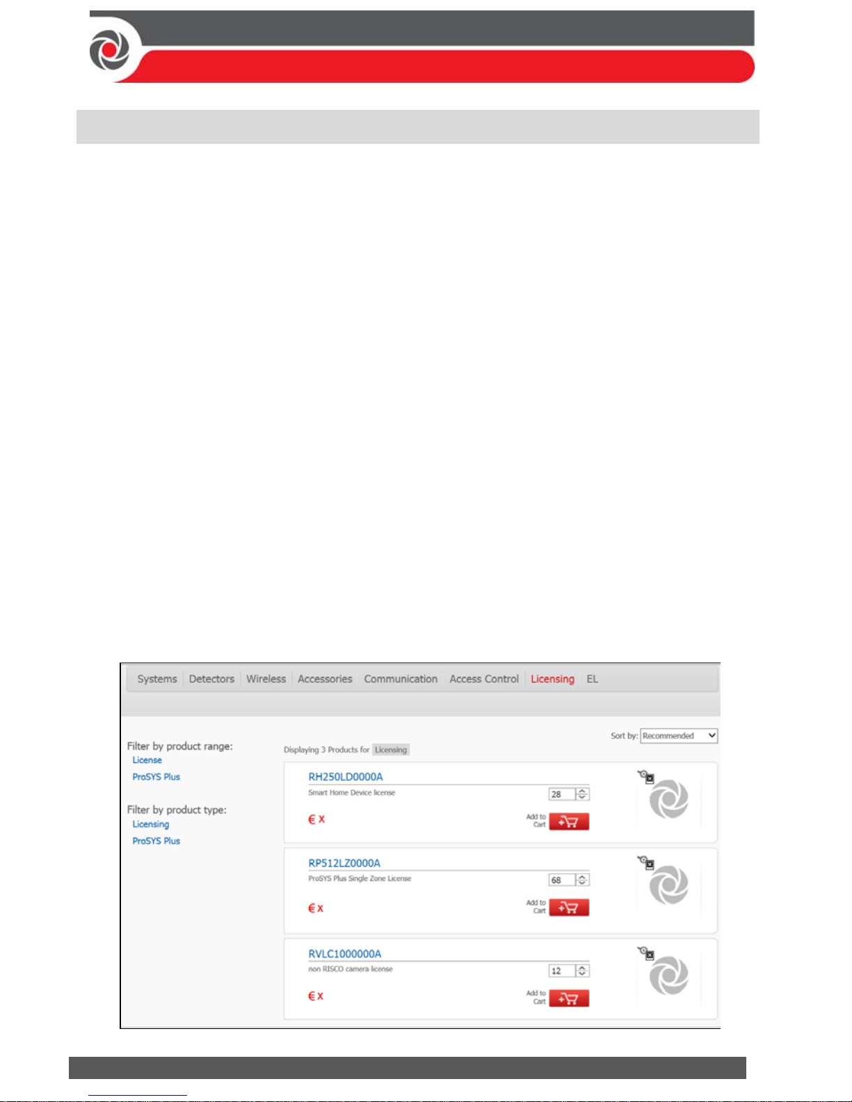
09/2016 Page 56 5IN2371 C
Licensing Procedure
This appendix specifies the procedure for purchasing and activating licenses of the
following category:
ProSYS Plus – Zone licenses (base license of 64 zones)
There are two main steps to the Licensing procedure, as follows:
1. License purchasing: The RISCO customer can purchase an allocation of licenses
for a specific Installer Admin account in the RISCO Cloud. Each license category
has a separate allocation.
2. License activation: The Installer Admin activates licenses for a specific Panel ID
using the HandyApp. The number of activated licenses per Panel ID can be
either a part of the allocation or the entire allocation.
Note: Only users that are registered as Installer Admins in the RISCO Cloud can activate
a license in the HandyApp.
Purchasing Licenses from the RISCO Store
Every transaction in the RISCO Store is performed for a single Installer Admin
account.
To Purchase a License:
1. Select the required license part numbers and quantity for the ProSYS Plus
license category as shown in the following screen.
Page 57
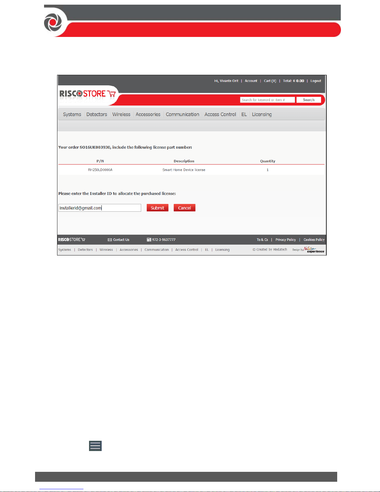
09/2016 Page 57 5IN2371 C
2. Upon completion of the purchasing transaction, the following screen will
appear.
3. Enter the Installer Admin ID email.
4. Click Submit.
License Activation via HandyApp
The Installer Admin can activate licenses for a specific Panel ID.
Note: An Installer Admin can activate licenses for a Panel on condition that the Panel ID
was pre-registered by the Installer Admin in the RISCO Cloud.
To Activate a License:
1. Open the HandyApp application on your smartphone.
Notes:
If HandyApp is not installed on your smartphone, download it from App Store or
Google Play.
Enter the HandyApp username and password using your RISCO web site
(riscogroup.com) login credentials.
If already installed on your smartphone, update HandyApp to the latest version.
2. Press the icon at the top left corner of the screen and then select
LICENSE ACTIVATION.
Page 58
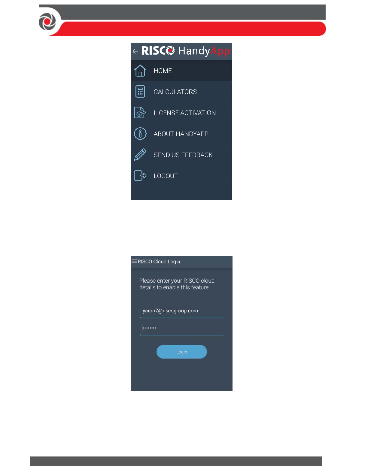
09/2016 Page 58 5IN2371 C
3. If the HandyApp registration email address is not identical to the Installer
Admin email address, the HandyApp will request a RISCO Cloud Installer
Admin login (for initial login only). Enter your RISCO Cloud Installer Admin
Username and Password.
4. The Panel Selection screen appears:
Page 59
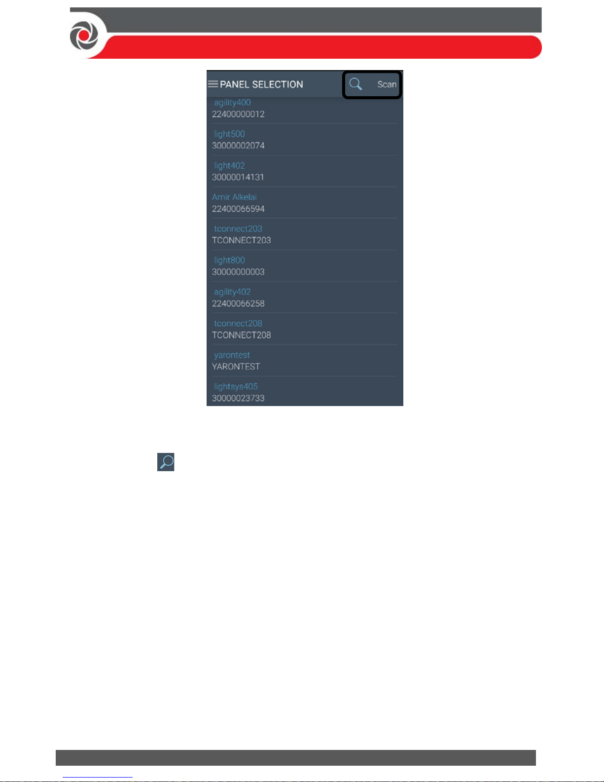
09/2016 Page 59 5IN2371 C
Note: If licenses were not purchased from the RISCO Store, no Panel IDs will appear.
5. You can either select a Panel ID from the list
or, press and enter the first digits of the Panel ID to filter according to
Panel IDs. For example, if you enter “421”, then only Panel IDs that begin with
“421” will be displayed.
or, press Scan and then point your smartphone’s camera over the QR code of
the Panel; the Panel ID automatically displays.
Page 60
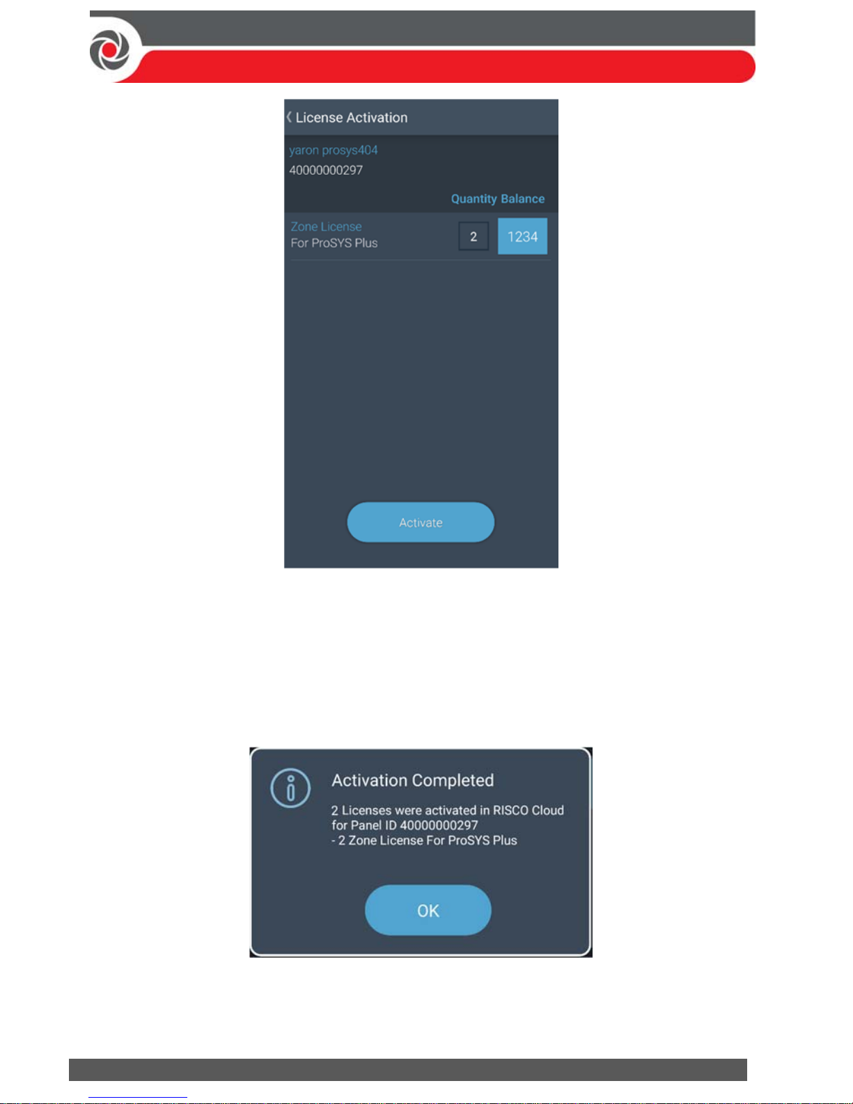
09/2016 Page 60 5IN2371 C
Balance indicates the number of available (purchased) licenses from the
Installer Admin License Allocation.
Quantity indicates the number of these licenses to activate for the selected
Panel ID.
6. In the Quantity box, enter the number of licenses to activate per each category.
7. Press the Activate button; the following success screen appears.
8. Press the OK button to take you back to the Panel Selection screen.
Page 61
09/2016 Page 61 5IN2371 C
Standard Limited Product Warranty
RISCO Ltd., its subsidiaries and affiliates (“Risco") guarantee Risco’s hardware products to be free from
defects in materials and workmanship when used and stored under normal conditions and in
accordance with the instructions for use supplied by Risco, for a period of (i) 24 months from the date of
connection to the Risco Cloud (for cloud connected products) or (ii) 24 months from production (for
other products which are non-cloud connected), as the case may be (each, the “Product Warranty
Period” respectively).
Contact with customers only. This Product Warranty is solely for the benefit of the customer who
purchased the product directly from Risco, or from any authorized distributor of Risco. Nothing in this
Warranty obligates Risco to accept product returns directly from end users that purchased the products
for their own use from Risco’s customer or from any installer of Risco, or otherwise provide warranty or
other services to any such end user. Risco customer shall handle all interactions with its end users in
connection with the Warranty, inter alia regarding the Warranty. Risco’s customer shall make no
warranties, representations, guarantees or statements to its customers or other third parties that suggest
that Risco has any warranty or service obligation to, or any contractual privy with, any recipient of a
product.
Return Material Authorization. In the event that a material defect in a product shall be discovered and
reported during the Product Warranty Period, Risco shall, at its option, and at customer's expense,
either: (i) accept return of the defective Product and repair or have repaired the defective Product, or
(ii) accept return of the defective Product and provide a replacement product to the customer. The
customer must obtain a Return Material Authorization (“RMA”) number from Risco prior to returning
any Product to Risco. The returned product must be accompanied with a detailed description of the
defect discovered (“Defect Description”) and must otherwise follow Risco’s then-current RMA
procedure in connection with any such return. If Risco determines in its reasonable discretion that any
Product returned by customer conforms to the applicable warranty (“Non-Defective Products”), Risco
will notify the customer of such determination and will return the applicable Product to customer at
customer’s expense. In addition, Risco may propose and assess customer a charge for testing and
examination of Non-Defective Products.
Entire Liability. The repair or replacement of products in accordance with this warranty shall be Risco’s
entire liability and customer’s sole and exclusive remedy in case a material defect in a product shall be
discovered and reported as required herein. Risco’s obligation and the Warranty are contingent upon
the full payment by customer for such Product and upon a proven weekly testing and examination of
the product functionality.
Limitations. The Product Warranty is the only warranty made by Risco with respect to the Products.
The warranty is not transferable to any third party. To the maximum extent permitted by applicable
law, the Product Warranty does not apply and will be void if: (i) the conditions set forth above are not
met (including, but not limited to, full payment by customer for the product and a proven weekly
testing and examination of the product functionality); (ii) if the Products or any part or component
thereof: (a) have been subjected to improper operation or installation; (b) have been subject to neglect,
abuse, willful damage, abnormal working conditions, failure to follow Risco’s instructions (whether oral
or in writing); (c) have been misused, altered, modified or repaired without Risco’s written approval or
combined with, or installed on products, or equipment of the customer or of any third party; (d) have
been damaged by any factor beyond Risco’s reasonable control such as, but not limited to, power
failure, electric power surges, or unsuitable third party components and the interaction of software
therewith or (e) any delay or other failure in performance of the product attributable to any means of
Page 62
09/2016 Page 62 5IN2371 C
communications, provided by any third party service provider (including, but not limited to) GSM
interruptions, lack of or internet outage and/or telephony failure.
BATTERIES ARE EXPLICITLY EXCLUDED FROM THE WARRANTY AND RISCO SHALL NOT BE
HELD RESPONSIBLE OR LIABLE IN RELATION THERETO, AND THE ONLY WARRANTY
APPLICABLE THERETO, IF ANY, IS THE BATTERY MANUFACTURER'S WARRANTY.
Risco makes no other warranty, expressed or implied, and makes no warranty of merchantability or of
fitness for any particular purpose. For the sake of good order and avoidance of any doubt:
DISCLAIMER. EXCEPT FOR THE WARRANTIES SET FORTH HEREIN, RISCO AND ITS
LICENSORS HEREBY DISCLAIM ALL EXPRESS, IMPLIED OR STATUTORY, REPRESENTATIONS,
WARRANTIES, GUARANTEES, AND CONDITIONS WITH REGARD TO THE PRODUCTS,
INCLUDING BUT NOT LIMITED TO ANY REPRESENTATIONS, WARRANTIES, GUARANTEES,
AND CONDITIONS OF MERCHANTABILITY, FITNESS FOR A PARTICULAR PURPOSE, TITLE
AND LOSS OF DATA. WITHOUT LIMITING THE GENERALITY OF THE FOREGOING, RISCO AND
ITS LICENSORS DO NOT REPRESENT OR WARRANT THAT: (I) THE OPERATION OR USE OF THE
PRODUCT WILL BE TIMELY, SECURE, UNINTERRUPTED OR ERROR-FREE; (ii) THAT ANY FILES,
CONTENT OR INFORMATION OF ANY KIND THAT MAY BE ACCESSED THROUGH THE
PRODUCT BY CUSTOMER OR END USER SHALL REMAIN SECURED OR NON DAMAGED.
CUSTOMER ACKNOWLEDGES THAT NEITHER RISCO NOR ITS LICENSORS CONTROL THE
TRANSFER OF DATA OVER COMMUNICATIONS FACILITIES, INCLUDING THE INTERNET, GSM
OR OTHER MEANS OF COMMUNICATIONS AND THAT RISCO’S PRODUCTS, MAY BE SUBJECT
TO LIMITATIONS, DELAYS, AND OTHER PROBLEMS INHERENT IN THE USE OF SUCH MEANS
OF COMMUNICATIONS. RISCO IS NOT RESPONSIBLE FOR ANY DELAYS, DELIVERY FAILURES,
OR OTHER DAMAGE RESULTING FROM SUCH PROBLEMS.
RISCO WARRANTS THAT ITS PRODUCTS DO NOT, TO THE BEST OF ITS KNOWLEDGE,
INFRINGE UPON ANY PATENT, COPYRIGHT, TRADEMARK, TRADE SECRET OR OTHER
INTELLECTUAL PROPERTY RIGHT
IN ANY EVENT RISCO SHALL NOT BE LIABLE FOR ANY AMOUNTS REPRESENTING LOST
REVENUES OR PROFITS, PUNITIVE DAMAGES, OR FOR ANY OTHER INDIRECT, SPECIAL,
INCIDENTAL, OR CONSEQUENTIAL DAMAGES, EVEN IF THEY WERE FORESEEABLE OR RISCO
HAS BEEN INFORMED OF THEIR POTENTIAL.
Risco does not install or integrate the product in the end user security system and is therefore not
responsible for and cannot guarantee the performance of the end user security system which uses the
product.
Risco does not guarantee that the product will prevent any personal injury or property loss by burglary,
robbery, fire or otherwise; or that the product will in all cases provide adequate warning or protection.
Customer understands that a correctly installed and maintained alarm may only reduce the risk of
burglary, robbery or fire without warning, but is not an assurance or a guarantee that such an event will
not occur or that there will be no personal injury or property loss as a result thereof. Consequently Risco
shall have no liability for any personal injury, property damage or loss based on a claim that the
product fails to give warning.
No employee or representative of Risco is authorized to change this warranty in any way or grant any
other warranty.
Page 63
09/2016 Page 63 5IN2371 C
RTTE Compliance Statement
Hereby, RISCO Group declares that this equipment is in compliance with the essential requirements
and other relevant provisions of Directive 1999/5/EC. For the CE Declaration of Conformity please refer
to our website:
www.riscogroup.com
Contacting RISCO Group
RISCO Group is committed to customer service and product support. You can
contact us through our website www.riscogroup.com or via the following RISCO
branches:
Australia
Tel: + 542-991-1800
France
Tel: +33-164-73-28-50
Spain
Tel: +34-91-490-2133
Belgium (Benelux)
Tel: +32-2522-7622
Israel
Tel: +972-3-963-7777
United Kingdom
Tel: +44-(0)-161-655-5500
[email protected]
China (Shanghai)
Tel: +86-21-52-39-0066
[email protected]
Italy
Tel: +39-02-66590054
[email protected]
USA
Tel: +1-631-719-4400
[email protected]
This RISCO product was purchased at:
Page 64
09/2016 Page 64 5IN2371 C
© RISCO Group 2016. All rights reserved. No part of this document may be
reproduced in any form without prior written permission from the publisher.
 Loading...