

Portuguêse Italiano Español English Français
Installation & Programming Manual
Manual de Instalación y de Programación
Manuale di Installazione e Programmazione
Manual de Instalação e de Programação
Guide d'installation et de Programmation

2

Table of Contents
ProSound – Installation Instructions................................................................................ 4
Introduction........................................................................................................................ 4
Main Features................................................................................................................... 4
Installation..........................................................................................................................
LED Indication...................................................................................................................
Jumper Settings................................................................................................................ 5
DIP-switch Settings..........................................................................................................
Terminal Block Wiring......................................................................................................
Technical Specifications.................................................................................................. 8
Ordering Part numbers....................................................................................................
External Sounder – ProSYS Programming Instructions
Introduction........................................................................................................................ 9
Adding / Deleting the ProSound.....................................................................................
Installer Menu: Configuring the ProSound Parameters .............................................
Installer Menu: System.................................................................................................... 11
User Menu: Diagnostics ..................................................................................................
User Menu: Sounder Version.........................................................................................
Event Log Messages: ...................................................................................................... 12
.................................................. 9
English
4
5
6
6
8
9
9
11
12
3

ProSound – Installation Instructions
Introduction
RISCO Group’s External Sounder combines high performance and reliability with an exclusive design,
making it the perfect finishing touch for your burglary and fire alarm installations.
ProSound can be connected to any alarm system, or it can be installed on the BUS RISCO Group’s
ProSYS integrated security system. When installed in conjunction with the ProSYS a whole new level
of remote diagnostics and control becomes available, saving you time and reducing repeat site visits.
Main Features
Long life SLT strobe (patent pending)
UV-treated vandal proof polycarbonate
housing
Double skin with internal metal cover
Auto recharging battery circuit
Automatic low battery disconnection
(below 10.5V) for protection against
battery deep discharge
Double tamper protection (Wall & Cover)
Anti-Approach, anti foam proximity
protection (3cm)
Installation
The sounder should be mounted in a difficult to access location to minimize tampering risk, on a flat
mounting surface.
To mount the sounder:
IMPORTANT:
!
The sounder is designed to operate under harsh environmental conditions. However,
stormy weather (e.g. heavy rain, snow, or hail) may cause activation of the anti
approach relay (RS200WAP000A). Therefore, it is recommended to mount the sounder
with anti approach protection in an area protected from rain (e.g. under the eaves).
NOTE:
Before wiring the sounder, ensure that the connection to a power source is switched
OFF.
1. Open the front cover by removing the case locking screw located at the bottom of
the unit.
2. Hold the mounting pattern template (supplied) against the wall and mark the
locations for the mounting holes (4 mounting holes are available). Drill the desired
mounting holes and place the screw anchors.
3. Insert the wires through the hole at the back cover.
4. Mount the back unit to the wall using the supplied screws, 3.9mm, 32mm length
screws (DIN 7981 3.9X32 ZP).
5. Remove the internal metal cover by removing the locking screw located at the
bottom of the cover.
6. Complete all wiring and set the jumpers and DIP-switches as required.
7. Insert and connect the back-up battery (SLA rechargeable 12V, 2.2 A/H, UL
approved).
8. Reattach the metal cover and then close the front plastic cover by reattaching the
screw located at the bottom.
Positive or negative triggering signal
Flexible strobe activation when
connected to RISCO Group’s ProSYS
Remote Diagnostics and Control when
connected to RISCO Group’s ProSYS
Dedicated trouble and anti approach
outputs
Protection from power supply inverted
connection
4
LED Indication
LED Description
POWER
The power LED indicates the sounder operation
On: 13.8VDC is applied to the sounder.
Off: No power supply to the sounder.
Flash: Indicates a trouble in the sounder.
LED2
Status LED indication
On: The LED terminal block input is connected to negative (pulled to COM).
Off: No connection to the LED terminal input.
NOTE:
In BUS configuration the LED operation will be defined from the ProSYS control
panel
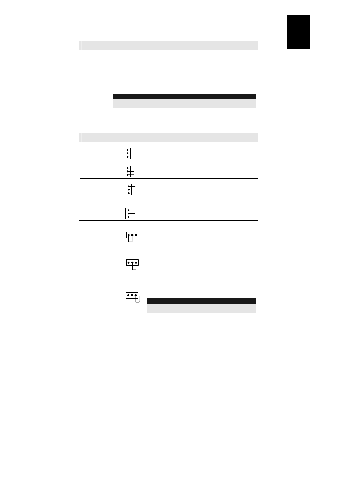
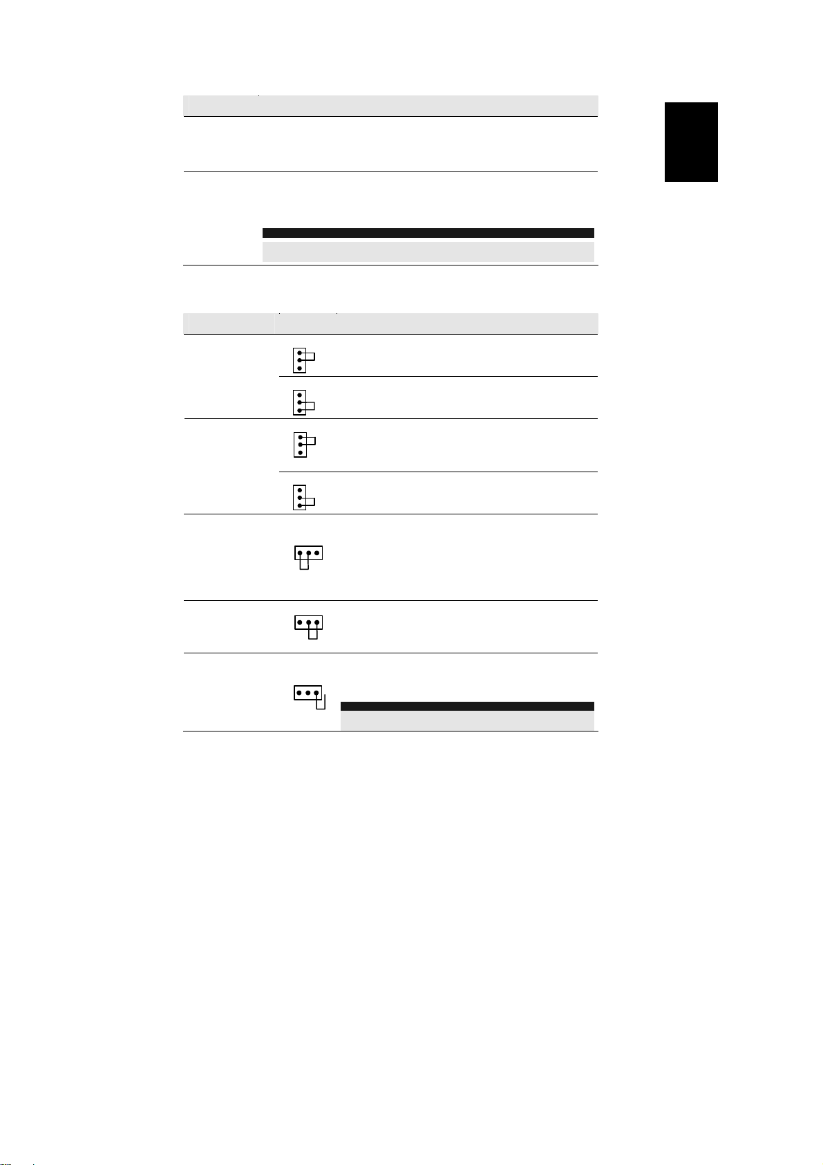
Jumper Settings
The sounder has three internal jumpers. Use the following table to configure the jumpers accordi ng to
the desired configuration:
Jumper Description
STROB
(Default: AUTO)
TRIG
(Default: C+)
TAMPER
(Default: EXT)
STROB
STROB
TRIG
TRIG
TAMPER
INT
TAMPER
Defines the strobe operation mode.
AUTO
AUTO: The strobe will follow the sounder activation.
MAN: The strobe will follow the triggering of the ST input.
MAN
Select the triggering command that will activate the
sounder.
C -
C-: Use the C- terminal to trigger the sounder. (C
terminal is deactivated).
C+: Use the C+ terminal to trigger the sounder. (C
terminal is deactivated)
C +
Defines the TAMPER output operation (Wall and cover
tampering)
INT: The TAMPER output is disabled. Use this option
when the sounder is connected in a BUS configuration.
A tamper event indication will be reported via the BUS to
the control panel.
EXT: The TAMPER output is triggered upon a tamper
event, NC configuration.
+
-
English
EXT
TAMPER
1 PIN Only: The TAMPER output is triggered upon a
tamper event, EOL configuration. In this configuration an
internal EOL 2.2 KΩ resistor, within the sounder PCB, is
applied in serial to the output.
NOTE FOR 1 PIN ONLY SETUP:
A 2.2 KΩ resistor does not have to be externally connected when
using EOL configuration.
5
DIP-switch Settings
CONFIG Description
CONFIG: 1
(Default:
Battery Trouble)
CONFIG: 2
(Default:
Stand Alone)
CONFIG: 3
(Default:
3 minutes)
CONFIG: 4
(Default: Fast)
ID1 Description
ID1: 1-3
ID1: 4
Defines the triggering of the TRBL output as follows: (Stand Alone mode
only):
On: Follow any trouble in the sounder (low battery, input voltage, speaker
fault)
Off: Follow battery troubles only (Low voltage or fail in battery load test)
Defines the operation mode of the sounder:
On: BUS mode configuration. Use this option when the sounder is connected
the ProSYS BUS.
Off: Stand Alone configuration. Use this option to conn ect the sounder to an y
panel.
Defines the duration time of the sounder activation (Stand Alone mode only).
On: 5 minutes
Off: 3 minutes
Defines the siren sound.
On: Slow
Off: Fast
Used to set a unique BUS ID number for the sounder when connected in a BUS
mode configuration. Set the ID in the same manner as with all ProSYS
accessories.
Sounder's sound. When set to ON position, sound is adjusted to French
standard NFA2P.
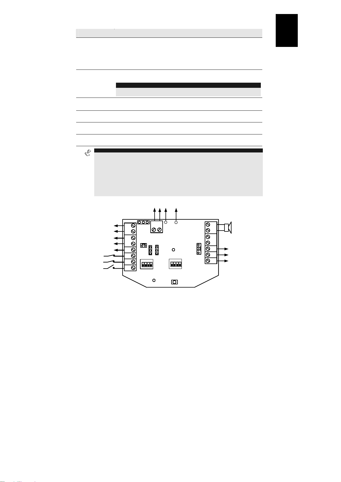
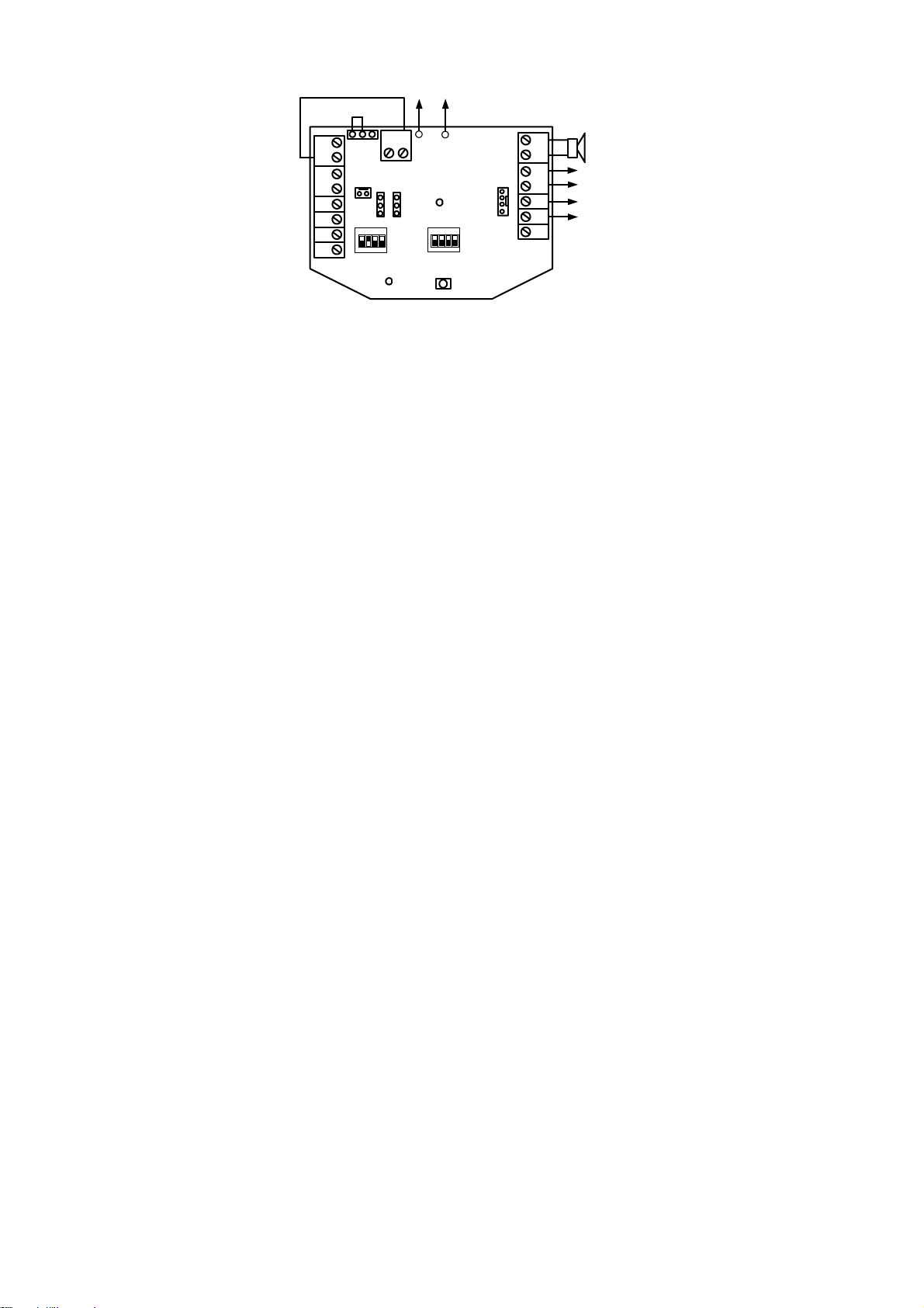
Terminal Block Wiring
The following explains the various wiring and connection procedures that must be performed when
wiring the sounder:
Terminal Description
LED
AUX RED
COM BLK
BUS YEL
BUS GRN
SPEAKER
PS +
PS-
This terminal is for triggering LED2. This LED is activated when it is
connected between LED and COM.
Input DC power terminals.
The maximum current that can be drawn from these terminals is 200mA
In BUS configuration, connect the wires respectively point to point according
to the indicated colors.
Connect these terminals only in BUS mode configuration, point to point
according to the indicated colors
Used for the connection of the internal speaker (8Ω 30W).
Use these terminals to connect an alternative power supply 13.8VDC 1.6A to
the sounder.
NOTES:
The maximum current that the sounder can draw from these terminals is 1.6A compared
to 200 mA from the AUX RED and COM BLK terminals.
When a power supply is connected to these terminals there is no need to connect a
power supply to the AUX RED and COM BLK terminals.
6
Terminal Description
TAMPER R
TAMPER F
Tamper outputs for (Wall and cover tampering). The connection of these
terminals depends on the setting of the TAMPER jumper:
INT: Connect the F to the COM (No connection to R terminal).
EXT: Connect the R and the F to a zone input.
1 PIN Only: Connect the R and the F to a zone input EOL. (An internal 2.2 K
PROX
(N.C)
TRBL
(N.O)
C+
EOL resistor is connected in serial to the output)
Connect these terminals to a zone input for the indication of Anti approach
alarm. (Stand Alone mode only)
NOTE:
You can connect the PROX terminals in serial to the TAMPER terminals in order to have
a single tamper indication from the sounder.
The trouble output is activated (closed) according to a trouble defined by the
setting of the troub le DIP-switch (CONFIG 1).
Terminal to positive, sounder is silent.
Terminal open, sounder is activated.
C-
Terminal to negative, sounder is silent.
Terminal open, sounder is activated
ST
Terminal to negative, strobe is activated.
Terminal open, strobe is deactivated.
NOTES:
1. The sounder will not operate when a battery is not connected or no power supply is connected to the
PS terminals.
2. After powering-up the sounder, it will not operate for a period of 20 seconds (sound and strobe) in
order to avoid accidental activation during installation.
3. After powering-up the sounder, the sounder inputs (C- or C+) will cause activation only if they have
been in normal (silent) state at least for 10 seconds.
4. The PROX and TRBL outputs are deactivated in BUS mode configuration.
5. To protect the battery against deep discharge, the battery will be automatically disconnected below
10.5 VDC.
Optional
13.8VDC
1.6 A
To
Battery
English
+
TRIG STROB
C -
C +
LED2
-
PS
BLK
AUTO
MAN
POWER
ON
1234
ID1
RED
SPEAKER
GRN
BUS
YEL
COM
BLK
AUX
RED
LED
To Internal
Speaker
13.8VDC ,
200 mA (max)
Status LED2
On/Off
Tamper Output
(0.5A, 24V N.C)
Anti Approach
Output
(0.1A, 24V N.C)
Trouble Output
70 mA max
+ 12 V
COM(-)
COM(-)
R
F
TAMPER
TAMPER
PROX
TRBL
C + C - ST
INT EXT
(To Int.
Tamper)
ON
1234
CONFIG
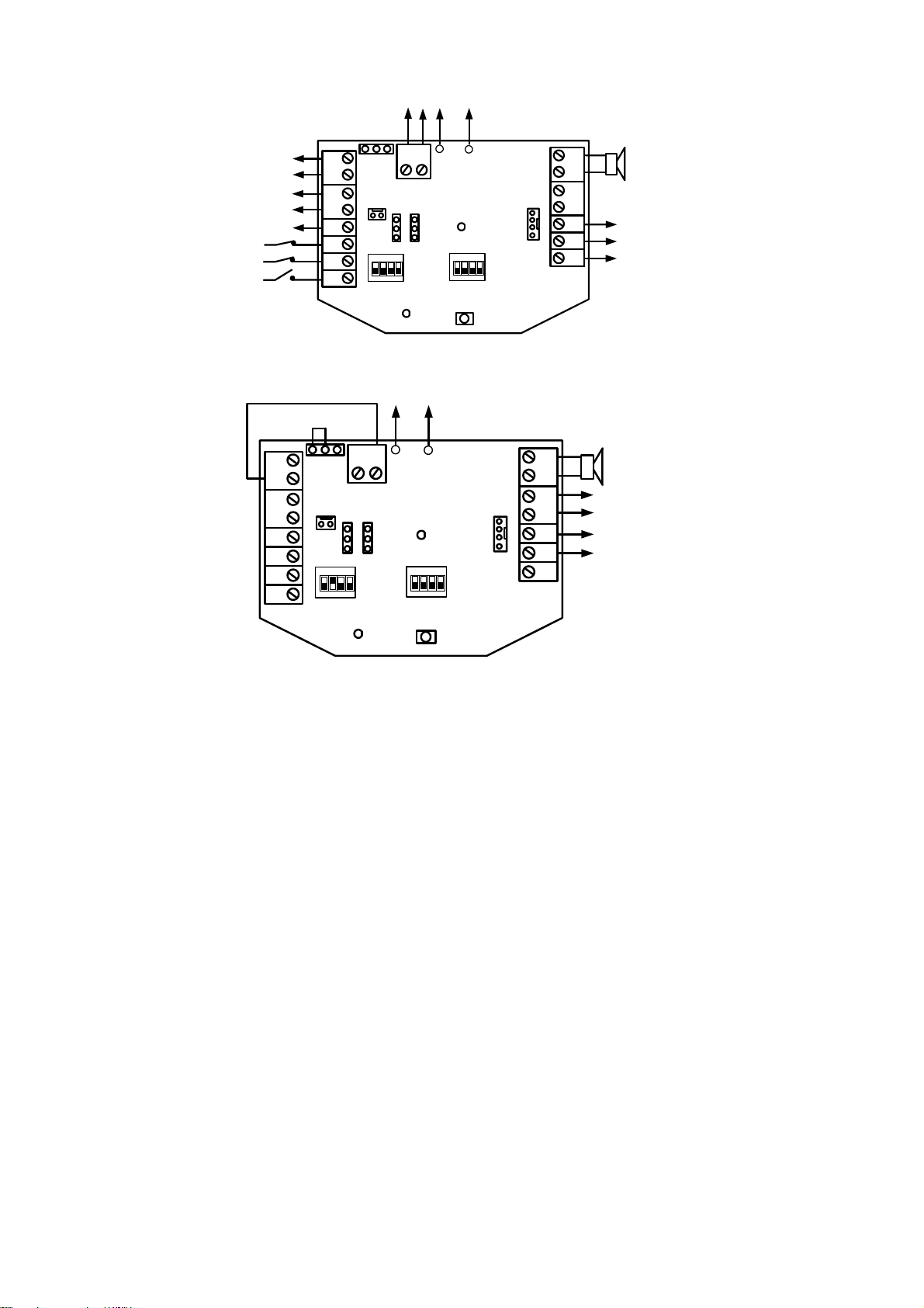
Figure 1 – Stand Alone Configuration
7
To
Battery
+
TRIG STROB
1234
-
PS
BLK
RED
POWER
AUTO
C -
MAN
C +
ON
1234
ID1
SPEAKER
BUS
COM
AUX
LED
To Inte rnal
Speaker
GRN
YEL
BLK
RED
To
ProSYS
Panel
BUS
R
F
TAMPER
TAMPER
PROX
TRBL
C + C - ST
INT EXT
(To Int.
Tamper)
ON
CONFIG
LED2
Figure 2 – BUS Configuration
Technical Specifications
Input DC Power
Standby Current Consumption
Battery charging current
Operating Current Consumption
(Sounder + Strobe)
Speaker Sound level
Tone frequency
Strobe light
Strobe lens
Strobe flash rate
Back-up battery (rechargeable)
Low battery protection
Ingress Protection
Operating Temperature
Humidity
Tamper contact
Proximity Anti foam contact
Housing material
Dimension (L x W x H)
Weight (without battery)
Compatibility
ProSYS compatibility
Regulated 13.5-14.2V, 200 mA maximum
54 mA + charge current
140 mA maximum
1.6A
106 dB @ 3 meters
1500-1800 Hz
Surface Light Technology SMT LED with 6000 mcd
Polycarbonate, available in amber, red or blue
60 times per minute (maximum)
SLA (Sealed Lead Acid) rechargeable 12V, 2.2 A/H, UL
approved,
Max Size (L x W x H): 17.8 cm x 6.4 cm x 3.5 cm
Automatic disconnection below 10.5 VDC
IP 43, IK 6
-25°C to 70°C (-13°F to 158°F)
95% maximum
0.5 A, 24 V, N.C. termination or internal EOL resistor
0.1 A, 24 V, N.C. termination
Polycarbonate with UV protection
30.5 cm X 21.8 cm X 11.6 cm
2.03 kg
All control panels
4-wire BUS, up to 300m from main panel
Ordering Part numbers
RS200WAP000A Outdoor polycarbonate sounder, amber lens cover, with anti-approach protection
RS200WA0000A Outdoor polycarbonate sounder, amber lens cover
8
External Sounder – ProSYS Programming Instructions
Introduction
The following section describes the additional dedicated ProSound software programming options,
added to the ProSYS software. Up to 8 sounders can be added to the system and each can be
assigned to any partition.
We recommend reading and fully understanding the ProSYS Installation and User Manual, before
programming the ProSound. It is also recommended to read the ProSound Installation section.
NOTE:
The ProSound is compatible with the ProSYS software Version 4.0 and above.
The ProSound can be programmed via the U/D Software from Version 2.0 and above
For maximum operation stability, it is best NOT to exceed a total of 300 meters (1000 feet) of wiring
between the ProSYS and the ProSound.
Adding / Deleting the ProSound
1. From the installer menu enter the Add/Delete menu: Quick Key [7][1].
2. Press [9][4] for Sounder Expander.
3. Use the
4. Press
5. Assign Sounder 1 to the selected partitions using the [1 to 8] keys and press
6. Use the
7. Use the
8. Use the
9. Repeat the process for the other sounders in the system (up to 8) or press
previous programming level.
Installer Menu: Configuring the ProSound Parameters
Configuring the sounder parameters is performed from the miscellaneous menu.
1. From the installer menu access the Miscellaneous menu, Quick Key [8].
2. Press [2] to access the Siren menu options.
3. Enter the digit of the sounder that you want to program and then press
can now program the sounder parameters as follows.
Miscellaneous: Siren
Quick Keys Parameter
[8][2][1]
[8][2][1][1]
[8][2][1][2]
[8][2][1][3]
key to choose either NONE or SIRN (Sounder).
.
.
key to choose if the sounder will be audible [Y] or not [N] and press .
key to choose if the squawk sound will be audible [Y] or not [N] and press .
key to choose if the squawk strobe is enabled [Y] or not [N] and press .
to return to the
. You
Strobe Control
Defines the Strobe operation mode
Always Off
The strobe is deactivated.
Follow Bell (Default)
The strobe is activated when the sounder bell is triggered.
Follow Alarm
The strobe is activated when an alarm occurs in the selected sounder’s partitions.
English
9

Miscellaneous: Siren
Quick Keys Parameter
[8][2][2]
[8][2][2][1]..[5]
[8][2][3]
[8][2][4]
[8][2][4][1]
[8][2][4][2]
[8][2][4][3]
[8][2][4][4]
[8][2][5]
[8][2][6]
[8][2][6][1]
[8][2][6][2]
Strobe Blink
Defines the number of times that the strobe will blink in a minute .
Strobe Blink options
[1]: 20 times per minute.
[2]: 30 times per minute.
[3]: 40 times per minute (Default)
Strobe Arm Squawk
The time that the strobe will blink when the system is armed.
Note: If the sounder’s squawk strobe is defined as NO (Refer to Adding / Deleting
the Outdoor Sounder section) this parameter will be ignored.
Siren LED
Defines the operation mode of the Status LED2.
Always On
The status LED2 is always on
Always Off
The status LED2 is deactivated
Follow Arm (Default)
The status LED2 is activated when any of the sounder selected partition is armed
(Away or Stay mode)
Follow Alarm
The status LED 2 is activated after any alarm condition
Proximity Level Response
Defines the time (seconds) for which a proximity violation must exist before the
sounder will trigger an anti approach alarm. The option 0 indicates that the
proximity is deactivated.
Battery Load Test
Enables to set the time period that the ProSYS will automatically generate a Load
test on the battery.
Never
The system will not set a battery load test
Every 24 Hours (Default)
The system will set a battery load test every 24 hours.
[4]: 50 times per minute
[5]: 60 times per minute.
Default: 01 Range: 01-20
(seconds)
Default: 3 Range: 0-9 seconds
10
Installer Menu: System
New System Parameters
[1][2][35]
[1][2][38]
Updated System Parameter
[1][2][13]
Audible Proximity Tamper
Yes: A proximity anti approach violation will activate the sounder.
No: A proximity anti approach violation will not activate the sounder and will be
regarded as trouble by the system.
Siren Auxiliary=Tamper
Yes: A sounder auxiliary trouble will be regarded as tamper alarm by the system.
No: A sounder auxiliary trouble will be regarded as trouble by the system.
Alarm ZE Cut
Yes: Produces an alarm if the communication between the main panel and any
zone expander or sounder is lost. A report is transmitted to the central station.
No: No alarm occurs. The system, however, produces a local trouble indication.
Default: No
Default: No
Default: Yes
User Menu: Diagnostics
The diagnostics menu enables to test parameters that reflect the operation of the sounder.
1. From the user menu press
2. Enter the Installer code (or sub-installer) and press
3. Press [9][3] to for the Siren diagnostic menu.
4. Enter the digit of the sounder that you want to test and then press
will perform the diagnostics test and a list of test parameters will appear, as indicated in
the table below.
5. Use the keys to view the diagnostics test results.
NOTE:
The diagnostic features can be also performed from Upload/Download software, locally or remotely.
[4] to access the Maintenance menu.
.
. The system
Maintenance: Siren Diagnostics
Quick Keys Parameter
[4][9][3]
Siren Diagnostics
Battery Voltage: Display battery voltage of the selected sounder.
Battery Load: Display battery voltage under load.
Auxiliary voltage: Display input voltage of the sounder from the AUX and COM
terminals.
Bell current: Displays the bell current consumption of the selected sounder.
Charge current: Displaying the current charging from the AUX and COM
terminals. The maximum current is 200mA.
English
11
User Menu: Sounder Version
1. From the user menu press [4] to access the Maintenance menu.
2. Enter the Installer code (or sub-installer) and press
3. Press [0][4] to enter the Siren version menu:
.
Maintenance: Siren Diagnostics
Quick Keys Parameter
[4][0][4]
Siren Version
The siren version supplies the following information for each of the sounders in
the system:
Sounder part number
Sounder Software Version
Sounder software date
Sounder software checksum
NOTE:
If a communication trouble with the sounder occurs, the “COMMUNICATION TROUBLE”
message appears.
Event Log Messages
The following list details the Outdoor Sounder dedicated event messages, as displayed on the keypad
LCD:
LCD Text Event Description
TAMPER SIREN=X Tamper alarm from sounder ID=X
TMP RSTR SIREN=X Tamper restore from sounder ID=X
PROX TMP SIREN=X Proximity tamper from approaching sounder ID=X
PROX TMP RS S=X Proximity tamper restore from sounder ID =X
NO COMM SIREN=X Bus communication failure with sounder ID=X
COMM OK SIREN=X Bus communication OK with sounder ID=X
LOW BAT SIREN=X Low battery trouble from sounder ID=X
LOW BAT RS S=X Low battery trouble restore from sounder ID=X
BAT LOAD SIREN=X Battery load trouble from sounder ID=X
BAT LOAD RS S=X Battery load trouble restore from sounder ID=X
CHARGE CURR S=X Battery charging trouble in sounder ID=X
CHRG CURR RS S=X Battery charging trouble restore in siren ID=X
AUX TRBL SIREN=X Auxiliary trouble on the sounder ID=X
AUX TRBL RS S=X Auxiliary trouble restore on the sounder ID=X
SPK TRBL SIREN=X Speaker trouble on sounder ID=X
SPK TRBL RS S=X Speaker trouble restore on sounder ID=X
PROX FAIL S=X Fail in the proximity anti approach protection in sounder X
PROX OK SIREN=X Proximity anti approach protection is restored in sounder X
12

Índice
ProSound – Instrucciones para Instalación..................................................................... 14
Introducción....................................................................................................................... 14
Características Principales ............................................................................................. 14
Instalación..........................................................................................................................
Indicación del LED ...........................................................................................................
Configuraciones de los Puentes .................................................................................... 15
Configuraciones de los Interruptores DIP ....................................................................
Cableado del Bloque de Terminales .............................................................................
Especificaciones Técnicas.............................................................................................. 19
Números de Producto para Pedido...............................................................................
Sirena Externa Instrucciones de Programación ProSYS
................................................ 20
Introducción....................................................................................................................... 20
Agregar / Suprimir el ProSound.....................................................................................
Menú del Instalador: Configurar los Parámetros del ProSound ...............................
Menú del Instalador: Sistema......................................................................................... 22
Menú del Usuario: Diagnósticos ....................................................................................
Menú del Usuario: Versión de la Sirena.......................................................................
Mensajes del Registro de Eventos .................................................................................. 23
14
15
16
16
19
20
20
22
23
Español

ProSound – Instrucciones para Instalación
Introducción
La Sirena Externa de RISCO Group combina alto rendimiento y confiabilidad con un diseño exclusivo,
logrando un toque de acabado perfecto para sus instalaciones de alarma de incendio y de robo.
ProSound puede ser conectado a cualquier sistema de alarma, o puede ser instalado en el BUS del
sistema de seguridad integrado ProSYS de RISCO Group. Cuando es instalada en conjunto con el
ProSYS un completo nivel nuevo de diagnóstico y control remotos se hace disponible, ahorrándole
tiempo y reduciendo repetidas visitas al local.
Características Principales
Estroboscopio de larga duración SLT (patente
pendiente)
Caja de policarbonato tratada con UV a prueba de
vandalismo
Carcasa doble con cobertura interior de metal
Circuito de la batería auto-recargable
Desconexión automática de la batería baja (inferior
a 10.5V) para protección contra su descarga
profunda.
Doble protección de tamper (Pared y Cobertura)
Protección Anti-Acercamiento, anti-espuma (3 cm)
Instalación
La sirena debe ser montada en una superficie de montaje plana, en un lugar de difícil acceso para
reducir al mínimo el riesgo de sabotaje.
Para montar la sirena:
IMPORTANTE:
!
La sirena esta designada para trabajar bajo condiciones ambientales severas. Sin
embargo, tiempo tormentoso (por ejemplo, lluvia fuerte, nieve o granizo) puede causar
la activación del relé de anti-acercamiento (RS200WAP000A). Por lo tanto, es
recomendado montar la sirena con protección anti-acercamiento, en un área protegida
de la lluvia (por ejemplo, debajo de las cornisas)
NOTA:
Antes de cablear la sirena asegúrese que la conexión a una fuente de energía esté
1. Abra la tapa frontal quitando el tornillo de fijación de la caja, situado en el fondo de la unidad.
2. Mantenga la plantilla de patrón de montaje (provista) contra la pared y marque las locaciones
3. Inserte los cables a través del agujero en la tapa posterior.
4. Monte la unidad posterior a la pared usando los tornillos provistos; tornillos de 3.9mm, 32mm
5. Quite la tapa interna de metal removiendo el tornillo de fijación situado en el fondo de la tapa.
6. Complete todo el cableado y fije los puentes y los interruptores DIP como requerido.
7. Inserte y conecte la batería de respaldo (SLA recargable 12V, 2.2 A/H, aprobada por UL)
8. Vuelva a unir la tapa de metal y después cierre la cubierta frontal de plástico, fijando
DESCONECTADA.
para los agujeros de montaje (están disponibles 4 agujeros de montaje). Perfore los agujeros
de montaje deseados y coloque los tacos de los tornillos.
de largo (DIN 7981 3.9X32 ZP).
nuevamente el tornillo situado en el fondo.
Activado por señales de entrada
negativas y positivas
Activación estroboscópica flexible
cuando conectado al ProSYS de
RISCO Group
Control Remoto y Diagnóstico cuando
conectado al ProSYS de RISCO Group
Salidas dedicadas a problemas y anti-
acercamiento
Protección contra conexión invertida de
la fuente de alimentación
14
Indicación del LED
LED Descripción
Power
El LED Power indica la operación de la sirena.
Encendido: 13.8VDC es aplicado a la sirena.
Apagado: No hay abastecimiento de energía a la sirena.
Parpadeo: Indica un problema en la sirena.
LED2
LED de indicación de estado
Encendido: El bloque de entrada del terminal del LED está conectado al
negativo (pasado al COM).
Apagado: No hay conexión a la entrada del terminal LED.
NOTA:
En la configuración del BUS la operación del LED será definida por el panel de
control del ProSYS.
Configuraciones de los Puentes
La sirena tiene tres puentes internos. Use la siguiente tabla para configurar los puentes según la
configuración deseada:
Jumper Descripción
STROB
(Predeterminado:
AUTO)
TRIG
(Predeterminado:
C+)
TAMPER
(Predeterminado:
EXT)
STROB
STROB
TRIG
TRIG
TAMPER
INT
TAMPER
Define el modo de operación estroboscópico.
AUTO
AUTO: El estroboscopio seguirá la activación de la sirena.
MAN: El estroboscopio seguirá la activación de la entrada
del ST.
MAN
Selecciona el comando de activación que accionará la
sirena.
C -
C-: Use el terminal C- para accionar la sirena. (EL
terminal C está desactivado).
C+: Use el terminal C+ para accionar la sirena. (EL
C +
terminal C
- está desactivado)
Define la operación de salida del TAMPER (Tamper en
Pared y tapa)
INT: La salida del TAMPER está desactivada. Use esta
opción cuando la sirena está conectada a una
configuración del BUS.
La indicación de un evento de tamper será informada, a
través del BUS al panel de control.
EXT: La salida del TAMPER es accionada en caso de un
evento de tamper, configuración NC.
Español
EXT
TAMPER
Solo 1 PIN: La salida del TAMPER es accionada por un
evento de tamper, configuración EOL. En esta
configuración una resistencia interna EOL 2.2 KΩ, dentro
del PCB de la sirena, es aplicado en serie a la salida.
NOTA PARA LA CONFIGURACIÓN DE solo 1 PIN:
Una resistencia de 2.2 KΩ no tiene que ser conectada
externamente al usar la configuración EOL.
15
Configuraciones de los Interruptores DIP
CONFIG Descripción
CONFIG: 1
(Predeterminado:
Problema en la
Batería)
CONFIG: 2
(Predeterminado:
Autónomo)
CONFIG: 3
(Predeterminado:
3 minutos)
CONFIG: 4
(Predeterminado:
Rápido)
Define la activación de la salida TRBL como sigue: (Solamente en el
modo Autónomo):
Encendido: Sigue cualquier problema en la sirena (batería baja, voltaje
de entrada, fallo en el altavoz)
Apagado: Sigue apenas problemas de batería (voltaje bajo o falla en la
prueba de carga de la batería)
Define el modo de operación de la sirena:
Encendido: modo de configuración BUS. Use esta opción cuando la sirena
está conectada al BUS del ProSYS.
Apagado: Configuración Autónomo. Use esta opción para conectar la sirena
a cualquier panel.
Define el tiempo de duración de activación de la sirena (Solamente en el
modo Autónomo).
Encendido: 5 minutos
Apagado: 3 minutos
Define el sonido de la sirena.
On: Lento
Off: Rápido
ID1 Descripción
ID1: 1-3
ID1: 4
Usado para establecer un número único de ID del BUS para la sirena cuando
conectada en un modo de configuración BUS. Establezca el ID de la misma
forma como con todos los accesorios del ProSYS.
Sonido de la sirena. Cuando se coloca en la posición ON, el sonido se ajusta
al estándar NFA2P francés.
Cableado del Bloque de Terminales
A seguir son explicados los varios procedimientos de cableado y conexión que deben ser ejecutados al
cablear la sirena:
Terminal Descripción
LED
AUX ROJO
COM NEGRO
BUS AMARILLO
BUS VERDE
ALTAVOZ
PS +
PS-
Este terminal es para accionar el LED2. Este LED es activado cuando
está conectado entre el LED y el COM.
Terminales de entrada de energía DC.
La máxima corriente que pude ser retirada de estos terminales es 200mA
En la configuración del BUS conecte los cables respectivamente punto a
punto según los colores indicados.
Conecte estos terminales solamente en el modo de configuración BUS, punto
a punto según los colores indicados.
Usado para la conexión del altavoz interno (8Ω 30W).
Use estos terminales para conectar una fuente alternativa de energía
13.8VDC 1.6A a la sirena.
NOTAS:
La máxima corriente que la sirena puede retirar de estos terminales es 1.6A
comparado a 200 mA de los terminales AUX ROJO y COM NEGRO.
Cuando una fuente de energía es conectada a estos terminales, no es necesario
16
Terminal Descripción
conectar una fuente de energía a los terminales AUX ROJO y COM NEGRO.
TAMPER R
TAMPER F
Salidas de tamper para (Tamper de Pared y Tapa). La conexión de estos
terminales depende de la configuración del puente TAMPER:
INT: Conecte el F al COM (Sin conexión al terminal R).
EXT: Conecte el R y el F a una entrada de zona.
Solamente 1 PIN: Conecte el R y el F a una entrada de zona EOL. (Una
resistencia i nterna de 2.2 K EOL es conectada en serie a la salida)
PROX
(N.C)
PROBLEMA
(N.O)
C+
Conecte estos terminales a una entrada de zona para indicación de alarma de
Anti-acercamiento. (Solamente en el modo Autónomo).
NOTA:
Usted puede conectar los terminales PROX en serie a los terminales TAMPER, a fin de
obtener una única indicación de tamper de la sirena.
La salida problema es activada (cerrada) según un problema definido por la
configuración del interruptor DIP problema (CONFIG 1).
Terminal al positivo; la sirena está silenciosa.
Terminal abierto, la sirena está activada.
C-
Terminal al negativo; la sirena está silenciosa.
Terminal abierto, la sirena está activada
ST
Terminal al negativo, el estroboscopio está activado.
Terminal abierto, el estroboscopio está desactivado.
NOTAS:
1. La sirena no funciona cuando una batería no está conectada o ninguna fuente de energía está
conectada a los terminales del PS.
2. Después de abastecer de energía a la sirena, esta no operará por un periodo de 20 segundos
(sonido y estroboscopio) a fin de evitar activación accidental durante la instalación.
3. Después de la sirena es abastecida de energía, las entradas de la sirena (C- o C+) causarán
activación solamente si estuvieran en estado normal (silencioso) durante por lo menos 10
segundos.
4. Las salidas PROX y TRBL son desactivadas en el modo de configuración BUS.
5. Para proteger la batería contra descarga profunda, la batería será automáticamente desconectada
cuando estuviera debajo de 10.5 VDC
Español
17
Salida Tamper
(0.5A, 24V N.C)
Salida
Anti-Acercamiento
(0.1A, 24V N.C)
Salida Problema
70 mA max
+ 12 V
COM(-)
COM(-)
R
F
PROX
TRBL
C + C - ST
TAMPER
TAMPER
R
F
TAMPER
TAMPER
PROX
TRBL
C + C - ST
Optcional
13.8VDC 1.6 A
INT EXT
(To Int.
Tamper)
TRIG STROB
ON
1234
CONFIG
LED2
Para
Batería
+
-
PS
BLK
RED
POWER
AUTO
C -
MAN
C +
ON
1234
ID1
Figura 1 – Configuración Independiente
Para Batería
+
-
PS
BLK
INT EXT
(To Int.
Tamper)
ON
1234
CONFIG
TRIG STROB
C -
C +
AUTO
MAN
RED
POWER
ON
1234
ID1
BUS
COM
AUX
Para altavoz
SPEAKER
BUS
COM
AUX
LED
GRN
YEL
BLK
RED
interno
13.8VDC ,
200 mA
(max)
LED de indicación
de estado
Encendido / Apagado
Para altavoz
SPEAKER
GRN
YEL
BLK
RED
LED
interno
LED2
Figura 2 – Configuración del BUS
18

Especificaciones Técnicas
Entrada de Energía DC
Consumo de Corriente en Estado
de Espera
Corriente de Carga de la Batería
Consumo de Corriente de
Operación (Sirena +
Estroboscopio)
Nivel del Sonido del Altavoz
Frecuencia de tono
Luz del Estroboscopio
Lente del Estroboscopio
Rango de Centelleo del
Estroboscopio
Batería de respaldo (recargable)
Protección de descarga de la
batería
Protección de Ingreso
Temperatura de Operación
Humedad
Contacto Tamper
Contacto de Proximidad Anti-
espuma
Material de la caja Policarbonato con protección ante UV
Dimensión (L x W x H)
Peso (sin batería)
Compatibilidad
Compatibilidad con el ProSYS Bus de 4 hilos, hasta 300m del panel principal
Regulado 13.5-14.2V, 200 mA máximo
54 mA + corriente de la carga
140 mA máximo
1.6A
106 dB a 3 metros
1500-1800 Hz
Tecnología de Luz de Superficie (SMT) LED con
6000 mcd
Policarbonato, disponible en ámbar, rojo y azul
60 veces por minuto (máximo)
SLA (Ácido de Plomo Aislado) recargable, 12V, 2.2
A/Hh, Aprobada UL, Tamaño Máximo (L x W x H):
17.8 cm x 6.4 cm x 3.5 cm
Desconexión automática abajo de 10.5 VDC
Estándar IP 43, IK 06
-25° C a 70° C (-13° F a 158° F)
95% máxima
0.5 A, 24 V, terminación NC o resistor EOL interno
0.1 A, 24 V, terminación N.C.
30.5 cm X 21.8 cm X 11.6 cm
2.03 kg
Todos los paneles de control
Números de Producto para Pedido
RS200WAP000A
RS200WA0000A
Sirena externa, de policarbonato, con cubierta de
lente ámbar, con protección anti-acercamiento
Sirena externa, de policarbonato, con cubierta de
lente ámbar
Español
19
Sirena Externa Instrucciones de Programación ProSYS
Introducción
La sección que sigue describe las opciones adicionales dedicadas a la programación del software
ProSound, agregadas al software del ProSYS. Hasta 8 sirenas pueden ser agregadas al sistema y
cada una puede ser asignada a cualquier partición.
Recomendamos leer y comprender totalmente los Manuales de Instalación y del Usuario de ProSYS,
antes de programar el ProSound. También se recomienda leer la sección de la instalación del
ProSound.
NOTA:
El ProSound es compatible con la Versión 4.0 del software del ProSYS y superior.
El ProSound puede ser programado a través del Software U/D a partir de la Versión 2.0 y superiores.
Para una estabilidad de operación máxima, es mejor NO exceder el total de 300 metros (1000 pies) de
cableado entre el ProSYS y el ProSound.
Agregar / Suprimir el ProSound
1. En el menú del Instalador, entrar al menú Agregar/Suprimir: Tecla Rápida [7][1].
2. Presionar [9][4] para Extensor de Sirena.
3. Usar la tecla
4. Presionar
5. Asignar Sirena 1 a las particiones seleccionadas usando las teclas [1 a 8] y presionar
6. Usar la tecla
7. Usar la tecla
8. Usar la tecla
.
9. Repetir el proceso para las otras sirenas existentes en el sistema (hasta 8) o presionar
retornar al nivel de programación anterior.
Menú del Instalador: Configurar los Parámetros del ProSound
La configuración de los parámetros de la sirena es realizada en el menú Varios.
1. En el menú del instalador, acceder al menú Varios, Tecla Rápida [8].
2. Presionar [2] para tener acceso a las opciones del menú Sirena.
3. Introducir el dígito de la sirena que quiere programar y presionar
programar los parámetros de la sirena como sigue.
Varios: Sirena
Teclas Rápidas Parámetro
[8][2][1]
[8][2][1][1]
[8][2][1][2]
[8][2][1][3]
para elegir entre NINGUNO o SIRENA.
.
para elegir si la sirena será audible [S] o no [N] y presionar .
para elegir si el sonido de aviso será audible [S] o [N] y presionar .
para elegir si el estroboscopio de aviso será audible [S] o [N] y presionar
. Usted puede ahora
Control del Estroboscopio
Define el modo de operación del Estroboscopio.
Siempre Apagado
El estroboscopio está desactivado.
Sigue Sirena (Predeterminado)
El estroboscopio es activado cuando la sirena es accionada.
Sigue Alarma
El estroboscopio es activado cuando ocurre una alarma en las particiones
seleccionadas de la sirena.
.
para
20

Varios: Sirena
Teclas Rápidas Parámetro
[8][2][2]
[8][2][2][1]..[5]
[8][2][3]
[8][2][4]
[8][2][4][1]
[8][2][4][2]
[8][2][4][3]
[8][2][4][4]
[8][2][5]
Parpadeo del Estroboscopio
Define el número de veces que el estroboscopio parpadeará en un minuto.
Opciones de parpadeo del Estroboscopio
[1]: 20 veces por minuto.
[2]: 30 veces por minuto.
[3]: 40 veces por minuto (Predeterminado)
Aviso del Estroboscopio
Predeterminado: 01 Rango: 01-20
[4]: 50 veces por minuto
[5]: 60 veces por minuto.
Armado
El tiempo que el estroboscopio parpadea cuando el sistema está armado.
Nota: Si el aviso del estroboscopio de la sirena está definido como NO (Refiérase
a la sección Agregar / Suprimir la Sirena Externo) este parámetro será ignorado.
LED de la Sirena
Define el modo de operación del Estado del LED2.
Siempre Encendido
El Estado del LED2 está siempre activado.
Siempre Apagado
El Estado del LED2 está desactivado.
Sigue Armado (Predeterminado)
El estado del LED2 se activa cuando cualquiera de las particiones seleccionadas
de la sirena es armada (modo Parcial o Total)
Sigue Alarma
El estatus del LED2 es activado después de cualquier condición de alarma.
Respuesta del Nivel de
Predeterminado: 3 Rango: 0-9 segundos
(segundos)
Proximidad
Define el tiempo (segundos) durante el cual debe existir una violación de
proximidad antes de que la sirena accione una alarma de anti-acercamiento. La
opción 0 indica que la proximidad está desactivada.
[8][2][6]
[8][2][6][1]
[8][2][6][2]
Prueba de Carga de la Batería
Permite establecer el periodo de tiempo en el cual el ProSYS automáticamente
producirá una prueba de Carga en la batería.
Nunca
El sistema no producirá una prueba de carga de la batería.
Cada 24 Horas (Predeterminado)
El sistema producirá una prueba de carga de la batería a cada 24 horas.
Español
21

Menú del Instalador: Sistema
Parámetros del Nuevo Sistema
[1][2][35]
[1][2][38]
Parámetro Actualizado del Sistema
[1][2][13]
Tamper Audible de Proximidad
Sí: Una violación de proximidad anti-acercamiento activará la sirena.
No: Una violación de proximidad anti-acercamiento no activará la sirena y será
considerada como un problema en el sistema.
Sirena Auxiliar=Tamper
Sí: Un problema de la sirena auxiliar será considerado como una alarma de tamper por
el sistema.
No: Un problema de la sirena auxiliar será considerado como un problema por el
sistema.
Corte Alarma Exp. de Zona
Sí: Produce una alarma si se pierde la comunicación entre el Panel Principal y cualquier
Expansor de Zona o sirena. Un informe es transmitido a la Estación Central.
No: No ocurre alarma. El sistema, sin embargo, produce una indicación local de
problema.
Predeterminado: No
Predeterminado: No
Predeterminado: Sí
Menú del Usuario: Diagnósticos
El menú diagnóstico permite probar parámetros que reflejen la operación de la sirena.
1. En el menú del usuario presionar
2. Introducir el código de Instalador (o sub-instalador) y presionar
3. Presionar [9][3] para el menú diagnóstico de la Sirena.
4. Introducir el digito de la sirena que usted quiere testear y presione
realizará la prueba de diagnóstico y aparecerá una lista de parámetros de la prueba,
como indicado en la tabla abajo..
5. Usar las teclas para ver los resultados de la prueba de diagnóstico.
NOTA:
Las características de diagnóstico pueden también ser realizadas desde el software Upload/Download
local o remotamente.
[4] para tener acceso al menú Mantenimiento.
.
. El sistema
22

Varios: Diagnósticos de la Sirena
Teclas Rápidas Parámetro
[4][9][3]
Diagnósticos de la Sirena
Voltaje de la Batería: Presenta el voltaje de la batería de la sirena seleccionada.
Carga de la Batería: Presenta el voltaje de la batería bajo carga.
Voltaje Auxiliar: Presenta el voltaje de en trada de la sirena de los terminales
AUX y COM.
Corriente de la Sirena: Presenta el consumo de corriente de la sirena de la
sirena seleccionada.
Corriente de carga: Presenta la carga actual de los terminales AUX y COM. La
corriente máxima es de 200mA.
Menú del Usuario: Versión de la Sirena
1. En el menú del usuario presionar [4] para tener acceso al menú Mantenimiento.
2. Introducir el código de Instalador (o sub-instalador) y presionar
3. Presionar [0][4] para entrar al menú versión de la Sirena:
.
Varios: Diagnósticos de la Sirena
Teclas Rápidas Parámetros
[4][0][4]
Versión de la Sirena
La versión de la sirena provee la siguiente información para cada una de las
sirenas en el sistema:
Número de la parte de la Sirena
Versión del Software de la Sirena
Fecha del software de la Sirena
Checksum del software de la Sirena
NOTA:
Si ocurre un problema de comunicación con la sirena, el mensaje “PROBLEMA
DE COMUNICACIÓN aparece.
Mensajes del Registro de Eventos
La lista siguiente detalla los mensajes de evento dedicados de la Sirena Externa, como aparecen en el
teclado numérico del LCD:
Texto en el LCD Descripción del Evento
TAMPER SIREN=X Alarma de tamper de la sirena ID=X
TMP RSTR SIREN=X Restauración tamper de la sirena ID=X
PROX TMP SIREN=X Tamper de proximidad de acercamiento de la sirena ID=X
PROX TMP RS S=X Restauración tamper de proximidad de la sirena ID =X
NO COMM SIREN=X Fallo de comunicación del Bus con la sirena ID=X
COMM OK SIREN=X Comunicación del Bus con la sirena ID=X OK
SIREN BAJA BAT=X Problema de batería baja de la sirena ID=X
BAT SIREN RS S=X Restauración problema de batería baja de la sirena ID=X
CARGA BAT SIRE=X Problema de carga de batería de la sirena ID=X
Español
23

Texto en el LCD Descripción del Evento
SIR BAT CAR RS=X Restauración problema de carga de batería de la sirena
CORR. CARGA S=X Problema de cargar batería en la sirena ID=X
CORR. CAR RS S=X Restauración problema de cargar batería en la sirena ID=X
AUX PROB SIREN=X Problema Sirena Auxiliar en la sirena ID=X
AUX PROBLEM RS=X Restauración problema Sirena Auxiliar en la sirena ID=X
SPK PROB SIREN=X Problema del altavoz en la sirena ID=X
SPK PROB RS S=X Restauración problema del altavoz en la sirena ID=X
PROX FALLO S=X Fallo en la proximidad de la protección anti-acercamiento
PROX OK SIREN=X Es restaurada proximidad de la protección anti-
ID=X
en la sirena X
acercamiento en la sirena X
24

Indice dei Contenuti
ProSound Sirena autoalimentata da esterno - Istruzioni per l’installazione ................... 26
Introduzione....................................................................................................................... 26
Caratteristiche Principali.................................................................................................. 26
Installazione.......................................................................................................................
Indicatori LED....................................................................................................................
Predisposizione ponticelli................................................................................................ 27
Predisposizione microinterruttori....................................................................................
Cablaggio morsettiere......................................................................................................
Caratteristiche Tecniche.................................................................................................. 31
Codici Prodotto.................................................................................................................
Sirena da esterno - Istruzioni per la programmazione tramite sistema ProSYS
Introduzione....................................................................................................................... 32
Aggiunta / Cancellazione della Sirena Esterna ...........................................................
Menù di Programmazione Tecnica: Configurazione Parametri Sirena ...................
Menù Tecnico: Sistema................................................................................................... 34
Menù Funzioni Utente Manutenzione: Diagnostica ....................................................
Menù Funzioni Utente Manutenzione: Versione Sirena.............................................
Messaggi della Memoria Eventi..................................................................................... 36
26
27
28
28
31
............ 32
32
32
34
35
Italiano
25

ProSound Sirena autoalimentata da esterno - Istruzioni per
l’installazione
Introduzione
ProSound è la sirena autoalimentata di RISCO Group che oltre alla qualità ed affidabilità ha una
estetica esclusiva che dà il tocco finale a qualsiasi impianto antifurto o antincendio.
ProSound può essere connessa a qualsiasi sistema d’allarme o può essere collegata al BUS 485 dei
sistemi d’allarme ProSYS. Collegata ad un sistema ProSYS, ProSound può essere controllata e testata
in remoto senza la necessità di effettuare un intervento di verifica in loco.
Caratteristiche Principali
Lampeggiante SLT “long life” (brevetto in
corso)
Contenitore antivandalico in policarbonato con
trattamento UV
Contenitore metallico interno per una doppia
protezione meccanica
Circuito di auto-ricarica batteria
Scollegamento batteria (sotto 10.5V) per
proteggerla evitandone la scarica completa.
Dispositivo antimanomissione contro
l’apertura e la rimozione
Protezione antiavvicinamento e antischiuma
con circuito di prossimità (3 cm)
Installazione
La sirena va montata su una superficie piana in una posizione non accessibile facilmente al fine di
minimizzare il rischio di manomissioni.
Per montare la sirena:
IMPORTANTE:
!
La sirena è progettata per fu nziona re in am bienti con cond izio ni cri tiche ma, in caso di
tempo cattivo che può provocare forte pioggia, neve o grandine, si può verificare la
possibilità di attivazione del si stema di anti-avvicinamento (modello sire na
RS200WAP000A). Per il motivo spieg ato è consigli abil e montare la sirena con il si stema di
anti-avvicinamento in una posizione protetta dalla pioggia (es.: sotto gronde o cornicioni).
IMPORTANTE:
!
Prima di cablare la sirena assicurarsi che l’alimentazione sia scollegata.
1. Aprire il coperchio frontale rimuovendo la vite di fissaggio posizionata nella parte inferiore
dell’unità.
2. Utilizzare la dima fornita con l’unità per marcare i punti dei 4 fori di fissaggio della sirena. Forare
con il trapano i punti marcati e posizionare i tasselli (normalmente da 6 mm. di diametro)
3. Passare i cavi della sirena attraverso il foro situato nella parte posteriore del contenitore.
4. Montare l’unità a muro utilizzando le viti fornite (DIN 7981 3.9X32 ZP).
5. Rimuovere il contenitore metallico interno svitando la vite posizionata nella parte inferiore dello
stesso.
6. Completare il cablaggio e predisporre ponticelli e microinterruttori come richiesto.
7. Inserire e collegare una batteria in tampone ricaricabile tipo SLA 12V, 2.2 A/H.
8. Rimontare il contenitore metallico e poi chiudere il coperchio in policarbonato fissandolo con la vite
posizionata nella parte bassa del contenitore.
Comando di attivazione positivo o negativo
Attivazione programmabile del
lampeggiante quando la sirena è collegata
ai sistemi ProSYS via Bus RS-485
Diagnostica e Controllo remoto con la
sirena collegata ai sistemi ProSYS via Bus
RS-485
Uscite di anomalia e antiavvicinamento
dedicate
Protezione contro l’inversione di polarità
sull’ingresso di alimentazione e sulla
batteria
26

Indicatori LED
LED Descrizione
POWER
Il LED “Power" indica che la sirena è in funzione
Acceso: una tensione di 13.8Vcc è applicata all’ingresso di alimentazione
della sirena.
Spento: Nessuna tensione all’ingresso di alimentazione della sirena.
Lampeggiante: Indica una condizione di anomalia della sirena o, se collegata
via Bus RS-485, può anche indicare sirena non programmata o sistema
ProSYS in programmazione tecnica.
LED2
Indicatore LED di stato
Acceso: Il morsetto per l’ingresso LED è collegato al negativo (COM).
Spento: Il morsetto per l’ingresso LED non è cablato.
NOTA:
Nella configurazione BUS le funzioni associate al LED di stato dipendono dalla
programmazione del sistema ProSYS
Predisposizione ponticelli
La sirena ha tre ponticelli interni. Utilizzare la tabella che segue per predisporre opportunamente questi
ponticelli come da funzionamento desiderato:
Ponticello Descrizione
STROB
(Default: AUTO)
TRIG
(Default: C+)
TAMPER
(Default: EXT)
STROB
STROB
TRIG
TRIG
TAMPER
INT
TAMPER
TAMPER
Stabilisce il modo di funzionamento del lampeggiante.
AUTO
AUTO: il lampeggiante segue l’attivazione della sirena.
MAN: Il lampeggiante segue il comando presente
all’ingresso ST.
MAN
Comando di attivazione della sirena.
C -
C-: Utilizzare un comando negativo rimosso per
l’attivazione della sirena (il morsetto C+ è disattivato).
C+: Utilizzare un comando positivo rimosso per l’attivazione
della sirena (il morsetto C-
C +
è disattivato).
Configura il funzionamento dell’uscita TAMPER della sirena
(apertura e rimozione).
INT: L’uscita tamper ai morsetti è disabilitata. Questa
opzione và utilizzata quando la sirena è collegata ai sistemi
ProSYS via RS-485 (config. BUS). Un evento di
manomissione verrà trasmesso via bus alla centrale.
EXT: L’uscita TAMPER si attiva in caso di manomissione
della sirena. L’uscita è NC e va collegata ad un ingresso
tamper della centrale.
EXT
Ponticello su un solo PIN: L’uscita TAMPER viene
attivata in caso di manomissione della sirena in
configurazione. L’uscita automaticamente viene
supervisionata tramite una resistenza di 2.2 KΩ inserita in
serie al circuito dell’uscita TAMPER.
NOTA PER LA PREDISPOSIZIONE UN SOLO PIN:
Non serve connettere una resistenza da 2.2 KΩ esternamente se
viene usata la configurazione EOL.
Italiano
27

Predisposizione microinterruttori
CONFIG. Descrizione
CONFIG: 1
(Default:
Anomalia batteria)
CONFIG: 2
(Default:
Stand Alone)
CONFIG: 3
(Default:
3 minuti)
CONFIG: 4
(Default:
modulazione
veloce)
Stabilisce l’attivazione dell’uscita TRBL (anomalia) come segue:
On: Segue qualsiasi anomalia della sirena (batteria scarica, anomalia ingresso
alimentazione, guasto altoparlante)
Off: Segue solo le anomalie della batteria (bassa tensione o test dinamico
batteria fallito)
Stabilisce il modo operativo della sirena:
On: Configurazione BUS. Da usare quando la sirena viene collegata via Bus
RS-485 alle centrali ProSYS.
Off: Configurazione “Stand Alone”. Da usare per collegare la sirena a qualsiasi
centrale di allarme.
Stabilisce la durata dell’attivazione della sirena (solo config. Stand Alone).
On: 5 minuti
Off: 3 minuti
Stabilisce il tipo di suono della sirena sia per la configurazione "Stand
Alone" che BUS.
On: modulazione lenta
Off: modulazione veloce
ID1 Descrizione
ID1: 1-3
ID1: 4
Utilizzato per predisporre l’indirizzo ID della sirena quando è collegata al Bus
dei sistemi ProSYS. Impostare l’indirizzo ID come per tutti gli altri accessori
ProSYS.
Regolazione suono della sirena. Se impostato su ON, il suono viene regolato
nella modalità francese NFA2P.
Cablaggio morsettiere
La tabella che segue spiega le connessioni che vanno effettuate nella procedura di cablaggio della
sirena:
Morsetto Descrizione
LED
AUX RED
COM BLK
BUS YEL
BUS GRN
SPEAKER
PS +
PS-
Questo morsetto viene usato per comandare il LED2. Questo LED si attiva
quando viene portato sul morsetto un negativo (COM).
Morsetti di ingresso alimentazione in corrente continua Vcc.
La corrente massima richiesta da questi morsetti è 200mA.
Nella configurazione BUS connettere questi morsetto seguendo i codici colore
riportati sulle rispettive morsettiere Sirena e Centrale ProSYS.
Connettere questi morsetti solo nella configurazione BUS seguendo i codici
colore riportati sulle rispettive morsettiere Sirena e Centrale ProSYS.
Usato per collegare l’altoparlante interno della sirena (8Ω,30W).
Usare questi morsetti per collegare un alimentatore esterno da 13.8Vcc, 1.6A
alla sirena.
NOTA:
La corrente massima che la sirena può richiedere da questi morsetti è 1.6A rispetto ai
soli 200 mA richiesti tramite i morsetto “AUX RED” e “COM BLK”.
Quando un alimentatore è connesso a questi morsetti, non va collegata alcuna
alimentazione ai morsetti “AUX RED” e “COM BLK”.
28

Morsetto Descrizione
TAMPER R
TAMPER F
Uscita di manomissione (apertura e rimozione). Il collegamento da effettuare
a questi morsetti dipende dalla predisposizione del ponticello TAMPER:
INSERITO: Collegamento del morsetto TAMPER F al negativo (COM) (l’altro
morsetto R non và collegato).
ESTRATTO: Collegare il morsetti TAMPER F e R ad un ingresso di zona in
centrale.
Su un solo PIN: Collegare i morsetti TAMPER F e R ad un ingresso di zona
bilanciato a 2.2 KΩ. (questa predisposizione inserisce una resistenza da 2.2
KΩ EOL in serie all’uscita TAMPER)
PROX
(N.C)
Se richiesto, connettere questi morsetti ad un ingresso di zona per gestire
una segnalazione dal circuito di antiavvicinamento della sirena. Normalmente
questa segnalazione è un tentativo di manomissione ed andrebbe collegata
ad un ingresso di zona sempre inserito (24 ore).
NOTA:
E’ anche possibile collegare questi morsetti in serie ai morsetti di manomissione
(TAMPER).
TRBL
(N.O)
C+
L’uscita di anomalia “TRBL” si attiva in funzione della configurazione del banco
di microinterruttori CONFIG.
Con il morsetto al positivo la sirena è a riposo.
Con il positivo rimosso la sirena è in allarme.
C-
Con il morsetto al negativo la sirena è a riposo.
Con il negativo rimosso la sirena è in allarme.
ST
Con il morsetto al negativo il lampeggiante in allarme.
Con il negativo rimosso il lampeggiante è a riposo.
NOTA:
1. La sirena non si attiverà se la batteria non è connessa o se non è presente l’alimentazione ai
morsetti di ingresso alimentazione (- PS + o ).
2. Dopo aver alimentato la sirena, questa non si attiverà per un periodo di 20 secondi (sia
l’altoparlante che il lampeggiante) al fine di evitare attivazioni accidentali durante l’installazione.
3. Dopo aver alimentato la sirena, gli ingressi di comando (C- o C+) causeranno l’attivazione della
sirena solo se questi ingressi sono stati a riposo (tensioni applicate) per almeno 10 secondi.
4. Le uscite PROX (anti-avvicinamento) e TRBL (Anomalia) sono disabilitate nella modalità di
configurazione BUS. Tutte le informazioni in questo caso saranno trasmesse via bus alla centrale
ProSYS.
5. Per proteggere la batteria dalla scarica completa, la sirena la scollega automaticamente quando la
tensione di alimentazione in ingresso scende al di sotto dei 10.5 Vcc.
Italiano
29

Figura 1 – Configurazione BUS
Figura 2 – Configurazione STAND ALONE
30

Caratteristiche Tecniche
Ingresso di alimentazione Vcc
Assorbimento di corrente a
riposo
Corrente di ricarica batteria
Assorbimento di corrente
(Sirena + Lampeggiante)
Pressione sonora altoparlante
Frequenza tono
Luce lampeggiante
Coperchio lampeggiante
Frequenza lampeggiante
Batteria in tampone
Protezione batteria
Protezione agenti atmosferici
Temperatura di funzionamento
Temp. di funzionamento
certificate
Umidità
Contatti di tamper
Contatti circuito antischiuma di
prossimità
Materiale contenitore
Dimensioni (L x W x H)
Peso (senza batteria)
Compatibilità
Compatibilità ProSYS
Livello di Prestazione
Da 13.5 a 14.2V— 200 mA massimo
54 mA + corrente di ricarica
140 mA massimo
1 A nominali, 1.6A di picco massimo.
101.5 dB a 3 metri, freq.za fondamentale 1600 Hz
1500-1800 Hz
Componente SMT con luminosità di 6000 mcd
Policarbonato, disponibile nel colore ambra
60 lampeggi al minuto (massimo)
Batteria al piombo sigillata ricaricabile 12V, 2.2 A/H,
Dimensioni (L x W x H): 17.8cm x 6.4 cm x 3.5 cm
Scollegamento automatico al di sotto dei 10.5 V—
IP 43 , IK 06
Da -25°C a 70°C
Da -25°C a 55°C
95% massimo
0.5 A, 24 V, N.C. o resistenza interna da 2200 Ω
0.1 A, 24 V, N.C.
Policarbonato con trattamento per protezione UV
30.5 cm X 21.8 cm X 11.6 cm
2.03 kg
Tutte le centrali
BUS 4 fili
II° livello IMQ
Italiano
Codici Prodotto
RS200WAP000A
RS200WA0000A
Sirena in policarbonato da esterno, coperchio lampeggiante di
colore ambra, fornita con circuito antiavvicinamento.
Sirena in policarbonato da esterno, coperchio lampeggiante di
colore ambra.
31

Sirena da esterno - Istruzioni per la programmazione
tramite sistema ProSYS
Introduzione
Questo manuale descrive le opzioni di programmazione relative la sirena ProSound aggiunte al
software delle centrali ProSYS. Le centrali ProSYS possono gestire fino a 8 sirene ProSound
assegnate a una o più partizioni del sistema.
Si consiglia di leggere attentamente il manuale di Installazione e Programmazione ProSYS nonché
quello Utente prima di programmare la Sirena ProSound. Si consiglia inoltre di leggere anche le
istruzioni di installazione della sirena ProSound oltre che il presente manuale.
NOTA:
La sirena da esterno ProSound è compatibile con tutti i sistemi ProSYS versione software 4.0 e
successive.
La sirena ProSound può essere programmata anche tramite il software di teleassistenza Versione 1.9 e
successive.
Per avere la massima stabilità e sicurezza di funzionamento senza utilizzare accorgimenti particolari, è
consigliabile non superare con il collegamento della sirena al bus la lunghezza di 300 metri.
Aggiunta / Cancellazione della Sirena Esterna
1. Dal menù di Programmazione Tecnica accedere al menù Accessori, Aggiungi/Cancella Moduli:
Sequenza di tasti rapidi [7][1].
2. Premere [9][4] per il Modulo Sirena.
3. Usare il tasto
4. Premere
5. Assegnare la Sirena 1 alle partizioni desiderate usando i tasti [1 - 8] per fare apparire una “S” sotto
le partizioni selezionate e premere
6. Usare il tasto
(abilita suono) [S] o no [N] e premere
7. Usare il tasto
riprodotta tramite l’altoparlante della sirena sotto forma di brevi toni acustici [S] o no [N] per non
riprodurre acusticamente questa segnalazione. Premere
8. Usare il tasto
essere segnalata tramite l’attivazione del lampeggiante della sirena [S] o no [N] per no, poi
premere
9. Ripetere la procedura descritta per le eventuali altre sirene (massimo 8) o premere il tasto
tornare al livello precedente del menù.
/ per selezionare NO (nessuna sirena) o SIRN (Sirena esterna).
/ per confermare l’opzione selezionata.
/ per confermare.
/ per selezionare se la sirena dovrà segnalare l’allarme acusticamente
/ per confermare.
/ se la segnalazione di inserimento/disinserimento deve essere
/ per confermare.
/ se la segnalazione di inserimento/disinserimento deve essere deve
/ per confermare.
per
Menù di Programmazione Tecnica: Configurazione Parametri Sirena
La configurazione dei parametri della sirena viene effettuata tramite il menù Varie.
1. Dal menù di Programmazione Tecnica selezionare il menù Varie, tasto rapido [8].
2. Premere [2] per accedere alle opzioni del menù Sirena.
3. Inserire il numero della sirena da programmare e premere il tasto
Adesso è possibile programmare i parametri di funzionamento della sirena come di
seguito spiegato.
32
/ .

Varie: Sirena
Tasti Rapidi Parametro
[8][2][1]
[8][2][1][1]
[8][2][1][2]
[8][2][1][3]
[8][2][2]
[8][2][2][1]..[5]
Lampeggiante
Stabilisce il modo di funzionamento del lampeggiante
Sempre spento
Il lampeggiante è disabilitato.
Segue Sirena (Default)
Il lampeggiante viene attivato quando viene attivata la sirena.
Segue Allarme
Il lampeggiante viene attivato quando si è verificata una condizione di allarme nella
partizione alla quale la sirena è associata.
Numero Lampeggi
Definisce il numero di lampeggi del lampeggiante in un minuto.
Numero di Lampeggi:
Opzioni
[8][2][3]
[8][2][4]
[8][2][4][1]
[8][2][4][2]
[8][2][4][3]
[8][2][4][4]
[8][2][5]
[1]: 20 volte al minuto.
[2]: 30 volte al minuto .
[3]: 40 volte al minuto (Default).
Lampeggio all’Inserimento
Tempo di attivazione del lampeggiante all’inserimento del sistema. Il valore 00
indica nessuna attivazione del lampeggiante all’inserimento.
Nota: Se la funzione di segnalazione Inserimento tramite lampeggiante è
configurata a NO (fare riferimento alla sezione “Agg/Canc Mdl Sirena Esterna” del
menù ACCESSORI), questo parametro verrà ignorato.
LED Sirena
Programma il funzionamento del LED 2 di stato della sirena.
Sempre Acceso
Il LED 2 di stato è sempre acceso
Sempre Spento
Il LED 2 di stato è sempre spe nto
Segue Inserimento (Default)
Il LED 2 di stato si attiva quando una delle partizioni associate alla sirena viene
inserita (sia in Totale che in Parziale).
Segue Allarme
Il LED 2 di stato si attiva dopo ogni condizione d’allarme
Livello Sensore Prox.
Stabilisce il tempo in secondi di persistenza dell’evento prima che la sirena attivi
l’allarme di manomissione per avvicinamento. Il valore 0 indica che il circuito di
prossimità è disattivato.
[4]: 50 volte al minuto.
[5]: 60 volte al minuto.
Default: 01 Range: 01-20 sec.
Default: 3 Range: 0-9 secondi
Italiano
33

[8][2][6]
[8][2][6][1]
[8][2][6][2]
Test dinamico Batteria
Abilita il test dinamico della batteria della sirena.
Mai
Il sistema non effettuerà il test dinamico sulla batteria della sirena
Ogni 24 Ore (Default)
l sistema effettuerà il test dinamico sulla batteria della sirena ogni 24 ore.
Menù Tecnico: Sistema
Nuovi Controlli Sistema (rispetto alla versione precedente di ProSYS)
[1][2][35]
[1][2][38]
Controlli di Sistema aggiornati (rispetto alla versione precedente di ProSYS)
[1][2][13]
Allarme Proxy
Si: Il circuito di antiavvicinamento se attivato genererà un allarme tamper tramite la
sirena.
No: ll circuito di antiavvicinamento se attivato genererà solo una anomalia
visualizzata nel menù guasti e registrata in memoria eventi.
No 12 Volt Sirena =Tamper
Si: Una anomalia di alimentazione 12 Volt della sirena provocherà un allarme
tamper.
No: Una anomalia di alimentazione 12 Volt della sirena verrà registrata in memoria
eventi e nel menù guasti senza provocare alcun allarme tamper.
Tamper BUS
Si: Genera un allarme tamper per la perdita della comunicazione di un modulo di
espansione zone o di un modulo sirena. Viene anche trasmesso un allarme
digitale alla Società di Ricezione Eventi se programmato opportunamente il
relativo codice report.
No: Non viene generato nessun allarme. Il sistema comunque produrrà una
anomalia visualizzandola nel menù guasti e registrandola in memoria eventi.
Default: No
Default: No
Default: Si
Menù Funzioni Utente Manutenzione: Diagnostica
Il menù diagnostico permette di testare una serie di parametri fondamentali per il corretto
funzionamento della sirena.
1. Dal menù Funzioni Utente premere
2. Digitare il codice Tecnico (o il sub-tecnico) e premere il tasto
3. Premere i tasti di accesso rapidi [9][3] per entrare nel menù di diagnostica della Sirena.
4. Digitare il numero ID della sirena da testare e premere
diagnostica della sirena e mostrerà successivamente la lista dei test effettuati con i relativi
parametri riportati nella tabella che segue.
5. Usare i tasti
NOTA:
La diagnostica può anche essere effettuata tramite il software di Teleassistenza RISCO Group, in locale o
in remoto.
/
[4] per accedere al menù Manutenzione.
/ .
/ . Il sistema effettuerà la
/ per scorrere tra i risultati del test.
34

Manutenzione: Diagnostica Sirena
Tasti Rapidi Parametro
[4][9][3]
Diagnostica Sirena
Tensione Batteria Sirena (VOLT BATT): Visualizza la tensione della batteria
della sirena misurata in Volt.
Tensione Batteria Sirena con Carico (CON CARICO): Visualizza la tensione
della batteria della sirena misurata in Volt con un carico fittizio.
Tensione di alimentazione ingresso Sirena (VOLT AUX): Visualizza la
tensione di alimentazione in ingresso alla scheda elettronica della sirena, morsetti
AUX e COM.
Assorbimento Sirena in allarme (CARICO SIR): Visualizza il consumo di
corrente della sirena selezionata.
Corrente di ricarica batteria Sirena (RICARICA): Visualizza l’attuale corrente di
ricarica erogata tramite i morsetti AUX e COM della sirena per ricaricarne la
batteria. Il valore massimo di corrente disponibile non supera 200 mA.
Menù Funzioni Utente Manutenzione: Versione Sirena
1. Dal menu Funzioni Utente premere [4] per accedere al menu Manutenzione.
2. Inserire il codice Tecnico o il Sub-Tecnico e premere
/ .
3. Premere [0][4] per accedere al menu Versione Sirena:
Manutenzione: Diagnostica Sirena
Tasti rapidi Parametro
[4][0][4]
Versione Sirena
Il menu versione sirena fornisce le seguenti informazioni di ogni sirena collegata
al sistema:
Codice prodotto
Versione Software
Data Software
Checksum Software
NOTA:
Se si verifica un problema di comunicazione con la sirena, il messaggio
“ANOMALIA DI COMUNICAZIONE !” verrà visualizzato sul display.
Italiano
35

Messaggi della Memoria Eventi:
La lista che segue riporta i messaggi della sirena che vengono registrati in memoria eventi e visualizzati
sulla tastiera LCD:
Messaggio su LCD Descrizione dell’evento
TAMPER SIRENA=X Allarme Tamper Sirena ID=X
RST.TMP.SIRENA=X Ripristino Tamper Sirena ID=X
TMP.PROX SIR.=X Tamper circuito antiavvicinamento della Sirena ID=X
RST.TMP.PROX S=X Ripristino antiavvicinamento Sirena ID =X
NO COM SIRENA=X Anomalia di comunicazione sul bus della Sirena ID=X
COM OK SIRENA=X Ripristino comunicazione su bus della Sirena ID=X
BAT.SCAR.SIR.=X Batteria scarica Sirena ID=X
BAT.OK SIRENA=X Ripristino batteria della Sirena ID=X
GUASTO BAT SIR=X Guasto Batteria dopo test dinamico ID=X
RIPR. BAT.SIR=X Ripristino buon funzionamento batteria Sirena ID=X
NO RICARICA SR=X Anomalia di ricarica batteria Sirena ID=X
RIPR.RICAR.SIR=X Ripristino anomalia ricarica batteria Sirena ID=X
ANML. AUX SIR=X Anomalia Alimentazione AUX della Sirena ID=X
AUX OK SIRENA=X Ripristino anomalia alimentazione AUX Sirena ID=X
ANML. SPKR SIR=X Anomalia Altoparlante Sirena ID=X
SPKR OK SIRENA=X Ripristino Altoparlante Sirena ID=X
ANML.PROX SIR.=X Guasto del circuito di antiavvicinamento Sirena=X
PROX OK SIRENA=X Ripristino guasto circuito antiavvicinamento Sirena=X
36

Índice
ProSound – Instruções para Instalação .......................................................................... 38
Introdução.......................................................................................................................... 38
Características Principais................................................................................................ 38
Instalação...........................................................................................................................
Indicação do LED.............................................................................................................
Configurações dos Jumpers........................................................................................... 39
Configurações dos Interruptores DIP............................................................................
Fiação do Bloco de Terminais........................................................................................
Especificações Técnicas................................................................................................. 43
Códigos para Pedido .......................................................................................................
Sirene Externa Instruções de Programação ProSYS
Introdução.......................................................................................................................... 44
Adicionar / Apagar o ProSound......................................................................................
Menu do Instalador: Configurar os Parâmetros do ProSound..................................
Menu do Instalador: Sistema.......................................................................................... 46
Menu do Usuário: Diagnósticos.....................................................................................
Menu do Usuário: Versão da Sirene.............................................................................
Mensagens do Registro de Eventos ............................................................................. 47
..................................................... 44
38
39
40
40
43
44
44
46
47
Portuguêse

ProSound – Instruções para Instalação
Introdução
A Sirene Externa de RISCO Group combina um alto desempenho e segurança com um desenho
exclusivo, possibilitando um toque de acabamento perfeito para suas instalações de alarme de
incêndio e de roubo.
O ProSound pode ser conectado a qualquer sistema de alarme, ou pode ser instalado no BUS do
sistema de segurança integrado ProSYS da RISCO Group. Quando instalado em conjunto com o
ProSYS, um novo nível completo de diagnóstico e de controles remotos tornam se disponíveis,
economizando tempo e reduzindo repetidas visitas ao local.
Características Principais
Estrobo SLR de longa duração (patente pendente)
Encapsulamento de policarbonato tratado contra
raios UV e à prova de vandalismo
Cobertura dupla com tampa de metal interna
Recarga automática da bateria
Desconexão automática de bateria fraca (inferior a
10.5V) para proteção contra sua descarga intensa.
Dupla proteção de tamper (Parede e Tampa)
Proteção Antiaproximação, antiespuma (3 cm)
Instalação
A sirene deve ser instalada numa superfície de montagem plana, num local de difícil acesso para
reduzir ao mínimo o risco de sabotagem.
Para instalar a sirene:
IMPORTANTE:
!
A sirene é projetada para operar sobre condições ambientais difíceis. Entretanto,
tormentas (por exemplo, forte chuva, neve ou granizo) podem causar o acionamento do
relé de antiaproximação (RS200WAP000A). Portanto, recomenda-se instalar a sirene
com proteção antiaproximação, numa área protegida da chuva (por exemplo, debaixo
das calhas)
NOTA:
Antes de fazer a instalação elétrica da sirene certifique-se que a conexão da fonte de
energia está DESLIGADA.
1. Abra a tampa frontal retirando o parafuso de tranca da caixa, situado no fundo da unidade.
2. Mantenha o modelo do gabarito de montagem (fornecido) contra a parede e marque as
posições dos furos de montagem (encontram-se disponíveis 4 furos de montagem). Faça os
furos de montagem desejados e coloque as buchas dos parafusos.
3. Insira os cabos através do furo na tampa posterior.
4. Monte a unidade posterior na parede usando os parafusos fornecidos; parafusos de 3.9 mm,
32mm de comprimento (DIN 7981 3.9X32 ZP)
5. Retire a tampa interna de metal removendo o parafuso de tranca situado no fundo da tampa.
6. Complete toda a fiação e fixe os Jumpers e os interruptores DIP como necessário.
7. Insira e conecte a bateria de reserva (SLA recarregável 12V, 2.2 A/H, aprovada pela UL)
8. Volte a unir a tampa de metal e depois feche a cobertura frontal de plástico, fixando novamente
o parafuso situado no fundo.
Acionado por sinais negativos e
positivos
Acionamento flexível do estrobo quando
conectado ao ProSYS da RISCO Group
Controle Remoto e Diagnóstico quando
conectado ao ProSYS da RISCO Group
Saídas dedicadas para problemas e
antiaproximação
Proteção contra conexão invertida da
fonte de alimentação
38

Indicação do LED
LED Descrição
POWER
(Ligado)
O LED Power indica a operação da sirene.
Aceso: 13.8VDC é aplicado à sirene.
Apagado: Não há abastecimento de energia à sirene.
Piscando: Indica um problema na sirene.
LED2
LED de indicação de status
Aceso: O bloco de entrada do terminal do LED está conectado ao negativo
(passado ao COM).
Apagado: Não há conexão à entrada do terminal do LED.
NOTA:
Na configuração BUS a operação do LED será definida pelo painel de controle do
ProSYS.
Configurações dos Jumpers
A sirene tem três jumpers internos. Use a tabela seguinte para configurar os jumpers de acordo com a
configuração desejada:
Jumper Descrição
STROB
(Predefinido:
AUTO)
TRIG
(Predefinido: C+)
TAMPER
(Predefinido:
EXT)
STROB
STROB
TRIG
TRIG
TAMPER
INT
TAMPER
Define o modo de operação do estrobo.
AUTO
AUTO: O estrobo seguirá o acionamento da sirene.
MAN: O estrobo seguirá o acionamento da entrada do
ST(Estrobo).
MAN
Seleciona o comando de acionamento que ativará a
sirene.
C -
C-: Use o terminal C - para acionar a sirene. (O
terminal C + está desativado).
C+: Use o terminal C+ para acionar a sirene. (O
C +
terminal C -
está desativado)
Define a operação de saída do TAMPER (Tamper na
Parede e na tampa)
INT: A saída do TAMPER está desativada. Use esta
opção quando a sirene estiver conectada a uma
configuração BUS.
A indicação de um evento de tamper será informada,
através do BUS ao painel de controle.
EXT: A saída do TAMPER é acionada no caso de um
evento de tamper, configuração NC.
Portuguêse
EXT
TAMPER
Apenas 1 PINO: A saída do TAMPER é acionada por um
evento de tamper, configuração EOL. Nesta configuração
um resistor interno EOL 2.2 KΩ, dentro do PCB da sirene,
é aplicado em série à saída.
NOTA PARA A CONFIGURAÇÃO DE APENAS 1 PINO:
A conexão de um resistor externo de 2.2 KΩ não é necessária
quando a configuração EOL for usada.
39

Configurações dos Interruptores DIP
CONFIG Descrição
CONFIG: 1
(Predefinido:
Problema na
Bateria)
CONFIG: 2
(Predefinido:
Autônomo)
CONFIG: 3
(Predefinido:
3 minutos)
CONFIG: 4
(Predefinido:
Rápido)
ID1 Descrição
ID1: 1-3
ID1: 4
Define o acionamento da saída TRBL como segue: (Apenas no modo
Autônomo):
Aceso: Segue qualquer problema na sirene (bateria fraca, voltagem de
entrada, falha no alto-falante)
Apagado: Segue apenas problemas de bateria (voltagem baixa ou falha no
teste de carga da bateria)
Define o modo de operação da sirene:
Aceso: modo de configuração BUS. Use esta opção quando a sirene estiver
conectada ao BUS do ProSYS.
Apagado: Configuração modo Autônomo. Use esta opção para conectar a
sirene a qualquer painel.
Define o tempo de duração do acionamento da sirene (Apenas no modo
Autônomo).
Aceso: 5 minutos
Apagado: 3 minutos
Define o som da sirene.
On: Lento
Off: Rápido
Usado para estabelecer um número único de ID do BUS para a sirene quando
conectada num modo de configuração BUS. Estabeleça o ID da mesma forma
como com todos os acessórios do ProSYS.
Som do sounder. Ao definir a posição ON, o som é ajustado para o francês
NFA2P padrão.
Fiação do Bloco de Terminais
A seguir são explicados os vários processos de fiação e conexão que devem ser executados ao ser
feita a fiação da sirene:
Terminal Descrição
LED
AUX RED
COM BLK
BUS YEL
BUS GRN
SPEAKER
Este terminal é para acionar o LED2. Este LED é ativado quando está
conectado entre o LED e o COM.
Terminais de entrada de energia DC.
A máxima corrente que pode ser retirada destes terminais é 200mA
Na configuração BUS conecte os fios respectivamente ponto a ponto de
acordo com as cores indicadas.
Conecte estes terminais apenas no modo de configuração BUS, ponto a
ponto de acordo com as cores indicadas.
Usado para a conexão do alto-falante interno (8Ω 30W).
40

Terminal Descrição
PS +
PS-
TAMPER R
TAMPER F
Use estes terminais para conectar uma fonte alternativa de energia
13.8VDC 1.6A à sirene.
NOTAS:
A máxima corrente que a sirene pode retirar destes terminais é 1.6A comparado a 200
mA dos terminais AUX - VERMELHO e COM - PRETO.
Quando uma fonte de energia é conectada a estes terminais, não é necessário
conectar uma fonte de energia aos terminais AUX - VERMELHO e COM - PRETO.
Saídas de tamper para (Tamper de Parede e Tampa). A conexão destes
terminais depende da configuração do jumper TAMPER:
INT: Conecte o F ao COM (Sem conexão ao terminal R).
EXT: Conecte o R e o F a uma entrada de zona.
Apenas 1 PINO: Conecte o R e o F a uma entrada de zona EOL. (Um resistor
PROX
(N.C)
TRBL
(N.O)
C+
interno 2.2 KΩ EOL é conectado em séria à saída)
Conecte estes terminais a uma entrada de zona para indicação de alarme de
Antiaproximação. (Apenas no modo Autônomo).
NOTA:
Você pode conectar os terminais PROX em série aos terminais TAMPER, a fim de
obter uma única indicação de tamper da sirene.
A saída de problema é ativada (fechada) de acordo a um problema definido
pela configuração do interruptor DIP problema (CONFIG 1).
Terminal para positivo; a sirene está silenciosa.
Terminal aberto, a sirene está ativada.
C-
Terminal para negativo; a sirene está silenciosa.
Terminal aberto, a sirene está ativada.
ST
Terminal para negativo, o estrobo está ativado.
Terminal aberto, o estrobo está desativado.
NOTAS:
1. A sirene não opera quando uma bateria não estiver conectada ou nenhuma fonte de energia estiver
conectada aos terminais do PS.
2. Depois de abastecer de energia a sirene, esta não operará por um período de 20 segundos (som e
estrobo) a fim de evitar acionamento acidental durante a instalação.
3. Depois da sirene ter sido abastecida de energia, as entradas da sirene (C- o C+) causarão
acionamento somente se estiverem em estado normal (silencioso) durante pelo menos 10 segundos.
4. As saídas PROX e TRBL são desativadas no modo de configuração BUS.
5. Para proteger a bateria contra descarga profunda, esta será automaticamente desconectada quando
estiver abaixo de 10.5 VDC
Portuguêse
41

Saída Antiaproximação
Saída Tamper
(0.5A, 24V N.C )
(0.1A, 24V N.C)
Saída de Problema
70 mA max
+ 12 V
COM(-)
COM(-)
R
F
TAMPER
TAMPER
PROX
TRBL
C + C - ST
R
F
PROX
TRBL
C + C - ST
TAMPER
TAMPER
Optcional
13.8VDC 1.6 A
INT EXT
(To Int.
Tamper)
TRIG STROB
ON
1234
CONFIG
C -
C +
LED2
Para
Bateria
+
-
PS
BLK
RED
POWER
AUTO
MAN
ON
1234
ID1
Figura 1 – Configuração Autônoma
Para
Bateria
+
-
PS
BLK
AUTO
MAN
POWER
ON
1234
ID1
RED
INT EXT
(To Int.
Tamper)
ON
1234
CONFIG
TRIG STROB
C -
C +
Para
alto-falante
SPEAKER
GRN
BUS
YEL
COM
BLK
AUX
RED
LED
interno
13.8VDC ,
200 mA (max)
Para
alto-falante
SPEAKER
GRN
BUS
YEL
COM
BLK
AUX
RED
LED
interno
Para o BUS
do Painel
ProSYS
LED2
Figura 2 – Configuração BUS
42

Especificações Técnicas
Entrada de Energia DC
Consumo de Corrente no Estado
de Espera
Corrente de Carga da Bateria
Consumo de Corrente de Operação
(Sirene + Estrobo)
Nível do Som do Alto-falante
Freqüência de tom
Luz Estroboscópica
Lente do Estrobo
Medida de Brilho do Estrobo
Bateria de suporte (recarregável)
Proteção de descarga da bateria
Proteção de Ingresso
Temperatura de Operação
Umidade
Contato Tamper
Contato de Proximidade
Antiespuma
Material do estojo Policarbonato com proteção contra raios UV
Dimensão (C x L x A)
Peso (sem bateria)
Compatibilidade
Compatibilidade com o ProSYS Bus de 4 fios, até 300m do painel principal
Regulado 13.5-14.2V, 200 mA máximo
54 mA + corrente da carga
140 mA máximo
1.6A
106 dB a 3 metros
1500-1800 Hz
Tecnologia de Luz de Superfície (SMT) LED com
6000 mcd
Policarbonato, disponível em laranja, vermelho e
azul
60 vezes por minuto (máximo)
SLA (Chumbo-Ácido Selada) recarregável, 12V, 2.2
Ah, Aprovada UL, Tamanho Máximo (C x L x A): 17.8
cm x 6.4 cm x 3.5 cm
Desconexão automática abaixo de 10.5 VDC
IP 43, IK 06
-25° C a 70° C (-13° F a 158° F)
95% máxima
0.5 A, 24 V, terminação NF ou resistor EOL interno
0.1 A, 24 V, terminação N.F.
30.5 cm X 21.8 cm X 11.6 cm
2.03 kg
Todos os painéis de controle
Códigos para Pedido
RS200WAP000A Sirene externa, de policarbonato, com cobertura de lente laranja, com
RS200WA0000A Sirene externa, de policarbonato, com cobertura de lente laranja
proteção anti-aproximação
Portuguêse
43

Sirene Externa - Instruções de Programação ProSYS
Introdução
A seção que segue descreve as opções adicionais dedicadas à programação do software ProSound,
adicionadas ao software do ProSYS. Até 8 sirenes podem ser agregadas ao sistema e cada uma pode
ser atribuída a qualquer partição.
Recomendamos ler e compreender integralmente os Manuais de Instalação e do Usuário de ProSYS,
antes de programar o ProSound. Também recomendados ler a seção de instalação do ProSound.
NOTA:
O ProSound é compatível com a Versão 4.0 do software do ProSYS e superiores.
O ProSound pode ser programado através do Software U/D a partir da Versão 2.0 e superiores.
Para uma estabilidade máxima de operação, é melhor NÃO exceder o total de 300 metros (1000 pés)
de fiação entre o ProSYS e o ProSound.
Adicionar / Apagar o ProSound
1. No menu do Instalador, entrar ao menu Adicionar/apagar: Tecla Rápida [7][1].
2. Pressionar [9][4] para Expansor de Sirene.
3. Usar a tecla
4. Pressionar
5. Atribuir Sirene 1 às partições selecionadas usando as teclas [1 a 8] e pressionar
6. Usar a tecla
7. Usar a tecla
pressionar
8. Usar a tecla
pressionar
9. Repetir o processo para as outras sirenes existentes no sistema (até 8) ou pressionar
retornar ao nível de programação anterior.
Menu do Instalador: Configurar os Parâmetros do ProSound
A configuração dos parâmetros da sirene é realizada no menu Vários.
1. No menu do instalador, ter acesso ao menu Vários, Tecla Rápida [8].
2. Pressionar [2] para ter acesso às opções do menu Sirene.
3. Introduzir o dígito da sirene que quer programar e pressionar
agora programar os parâmetros da sirene como segue.
Vários: Sirene
Teclas Rápidas Parâmetro
[8][2][1]
[8][2][1][1]
[8][2][1][2]
para escolher entre NENHUM ou SIRENE.
.
para escolher se a sirene será audível [S] ou não [N] e pressionar .
para escolher se o toque da sirene ao armar será ativado [S] ou [N] e
.
para escolher se o Flash do estrobo ao armar será ativado [S] ou [N] e
.
. Você pode
Controle do Estrobo
Define o modo de operação do Estrobo.
Sempre Apagado
O estrobo está desativado.
Segue Sirene (Predefinido)
O estrobo é ativado quando a sirene é acionada.
.
para
44

ç
Vários: Sirene
Teclas Rápidas Parâmetro
[8][2][1][3]
[8][2][2]
[8][2][2][1]..[5]
[8][2][3]
[8][2][4]
[8][2][4][1]
[8][2][4][2]
[8][2][4][3]
[8][2][4][4]
[8][2][5]
[8][2][6]
[8][2][6][1]
[8][2][6][2]
Segue Alarme
O estrobo é ativado quando ocorre um alarme nas partições selecionadas da
sirene.
Intermitência do Estrobo
Define o número de vezes que o estrobo piscará num minuto.
Opções de intermitência do Estrobo
[1]: 20 vezes por minuto.
[2]: 30 vezes por minuto.
[3]: 40 vezes por minuto (Predefinido)
Flash do Estrobo quando
Armado
O tempo que o estrobo pisca quando o sistema está armado.
Nota: Se o Flash do estrobo da sirene está definido como NÃO (Refira-se à
seção Adicionar / Apagar a Sirene Externa) este parâmetro será ignorado.
LED da Sirene
Define o modo de operação do LED2 de Status.
Sempre Aceso
O LED2 de status está sempre ativado.
Sempre Apagado
O LED2 de status está desativado.
Segue Armado (Predefinido)
O LED2 de status é ativado quando qualquer uma das partições selecionadas da
sirene é armada (modo Parcial ou Total)
Segue Alarme
O LED2 de status é ativado depois de qualquer condição de alarme.
Resposta do Nível de
Proximidade
Define o tempo (segundos) durante o qual deve existir uma violação de
proximidade antes que a sirene acione um alarme de antiaproxima
indica que a proximidade está desativada.
Teste de Carga da Bateria
Permite estabelecer o período de tempo no qual o ProSYS automaticamente
produzirá um teste de Carga na bateria.
Nunca
O sistema não produzirá um teste de carga da bateria.
A Cada 24 Horas (Predefinido)
O sistema produzirá um teste de carga da bateria a cada 24 horas.
[4]: 50 vezes por minuto
[5]: 60 vezes por minuto.
Predefinido: 01 Variação: 01-20
(segundos)
Predefinido: 3 Variação: 0-9
segundos
ão. A opção 0
Portuguêse
45

Menu do Instalador: Sistema
Parâmetros do Novo Sistema
[1][2][35]
Tamper Audível de
Predefinido: Não
Proximidade
Sim: Uma violação de proximidade antiaproximação ativará a sirene.
Não: Uma violação de proximidade antiaproximação não ativará a sirene e será
considerada como um problema no sistema.
[1][2][38]
Parâmetro Atualizado do Sistema
[1][2][13]
Sirene Auxiliar = Tamper
Sim: Um problema da sirene auxiliar será considerado como um alarme de
tamper pelo sistema.
Não: Um problema da sirene auxiliar será considerado como um problema pelo
sistema.
Corte Alarme Exp. de Zona
Sim: Produz um alarme se a comunicação entre o Painel Principal e qualquer
Expansor de Zona ou sirene é perdida. Um relatório é transmitido à Estação
Central.
Não: Não ocorre alarme. O sistema, entretanto, produz uma indicação local de
problema.
Predefinido: Não
Predefinido: Sim
Menu do Usuário: Diagnósticos
O menu diagnóstico permite testar os parâmetros que refletem a operação da sirene.
1. No menu do usuário pressionar
2. Introduzir o código de Instalador (ou sub-instalador) e pressionar
3. Pressionar [9][3] para o menu diagnóstico da Sirene.
4. Introduzir o dígito da sirene que você quer testar e pressionar
realizará o teste de diagnóstico e aparecerá uma lista de parâmetros do teste, como
indicado na tabela abaixo.
5. Usar as teclas para ver os resultados do teste de diagnóstico.
NOTA:
As características de diagnóstico podem também ser realizadas desde o software Upload/Download
local ou remotamente.
[4] para ter acesso o menu Manutenção.
.
. O sistema
Vários: Diagnósticos da Sirene
Teclas Rápidas Parâmetro
[4][9][3]
Diagnósticos da Sirene
Voltagem da Bateria: Mostra a tensão elétrica da bateria da sirene selecionada.
Carga da Bateria: Mostra a tensão elétrica da bateria em carga.
Voltagem Auxiliar: Apresenta a tensão elétrica de entrada da sirene dos
terminais AUX e COM.
Corrente da Sirena: Apresenta o consumo de corre nte da sirena seleciona da.
Corrente de carga: Apresenta a carga atual dos terminais AUX e COM. A
máxima corrente é de 200mA.
46

Menu do Usuário: Versão da Sirene
1. No menu do usuário pressionar [4] para ter acesso ao menu Manutenção.
2. Introduzir o código de Instalador (ou sub-instalador) e pressionar
3. Pressionar [0][4] para entrar no menu versão da Sirene:
.
Vários: Diagnósticos da Sirene
Teclas Rápidas Parâmetros
[4][0][4]
Versão da Sirene
A versão da sirene fornece a seguinte informação para cada uma das sirenes no
sistema:
Código da sirene
Versão do Software da Sirene
Data do software da Sirene
Checksum (número de controle) do software da Sirene
NOTA:
Se ocorrer um problema de comunicação com a sirene, a mensagem
“PROBLEMA DE COMUNICAÇÃO” aparece.
Mensagens do Registro de Eventos
A lista seguinte detalha as mensagens de evento dedicadas à Sirene Externa, como aparecem no
teclado numérico do LCD:
Texto no LCD Descrição do Evento
TAMPER SIREN=X Alarme de tamper da sirene ID=X
REST TAMP SIRE=X Restauração do tamper da sirene ID=X
PROX TMP SIREN=X Tamper de proximidade de aproximação da sirene ID=X
PROX TMP RS S=X Restauração do tamper de proximidade da sirene ID =X
SEM COM SIREN=X Falha de comunicação do Bus com a sirene ID=X
COM SIREN OK=X Comunicação do Bus com a sirene ID=X OK
BT FRAC SIREN=X Problema de bateria fraca da sirene ID=X
REST BAT SIR S=X Restauração do problema de bateria fraca da sirene ID=X
CARG BAT SIREN=X Problema de carga de bateria da sirene ID=X
CARG BAT RS S=X Restauração do problema de carga de bateria da sirene ID=X
CORRT CARGA S=X Problema ao carregar bateria na sirene ID=X
CORR CARG RS S=X Restauração do problema ao carregar bateria na sirene ID=X
PROB AUX SIR =X Problema Sirene Auxiliar na sirene ID=X
RST PRB AUX S=X Restauração do problema de Sirene Auxiliar na sirene ID=X
SPK TRBL SIREN=X Problema do alto-falante na sirene ID=X
SPK TRBL RS S=X Restauração do problema do alto-falante na sirene ID=X
PROX FAIL S=X Falha na proximidade da proteção antiaproximação na sirene X
PROX OK SIREN=X Restauração do problema de proximidade da proteção antiaproximação
na sirene X
Portuguêse
47

48

Table des matières
ProSound – Mode d'installation ..................................................................................... 50
Principales caractéristiques ..................................................................................... 50
Installation................................................................................................................... 51
Indicateurs LED.......................................................................................................... 52
Réglages des cavaliers............................................................................................. 52
Réglage des commutateurs DIP (DIP-switchs)..................................................... 53
Câblage du bloc de connexion ................................................................................ 53
Câblage de la sirène à la ProSYS suivant la norme NF&A2P.........................56
Spécifications techniques......................................................................................... 56
Références catalogues des pièces......................................................................... 57
Sirène externe – Mode de programmation du ProSYS.............................................. 58
Introduction ................................................................................................................. 58
Ajout / Suppression du ProSound........................................................................... 58
Menu Installateur : Paramétrage du ProSound .................................................... 58
Menue Installateur : Système .................................................................................. 60
Nouveaux paramètres de système ......................................................................... 60
Paramètre de système mis à jour ........................................................................... 60
Menu Utilisateur : Diagnostics ................................................................................. 60
Menu Utilisateur : Version Sirène............................................................................ 61
Messages du Journal (Historique des évènements)............................................ 61
Français
49

ProSound - Mode d'installation
La sirène externe de RISCO Group associe haute performance et fiabilité à un modèle exclusif,
apportant à vos alarmes incendie et anti-intrusion la touche d'une finition parfaite.
La sirène ProSound peut être connectée à tout système d'alarme, ou installée sur le système BUS de
sécurité intégrée ProSYS de RISCO Group. L'installation avec le ProSYS permet l'accès à toute une
gamme nouvelle de diagnostics et contrôle à distance, économisant du temps et les visites répétées
sur sites.
Principales caractéristiques
Longue durée de vie des lumières flash
(stroboscope) SLT (en instance de
brevet),
Boîtier en polycarbonate traité UV à
l'épreuve d'attaques de vandalisme,
Double paroi avec couvercle interne
métallique,
Circuit de rechargement automatique de
la pile (batterie),
Déconnexion automatique en cas de
batterie faible (moins de 10,5V) pour une
protection contre un déchargement
excessif de la pile,
Double autoprotection (Paroi & Couvercle),
Protection de proximité anti-approche, anti-mousse
(3 cm),
Signal de déclenchement positif ou négatif,
Activation flexible du stroboscope en cas de
connexion au ProSYS de RISCO Group,
Diagnostics et contrôle à distance en cas de
connexion au ProSYS de RISCO Group,
Sorties anti-approche et attribution de pannes,
Protection contre toute éventuelle inversion de
branchement électrique.
50

Installation
La sirène doit être placée en un endroit difficile d'accès afin de réduire les risques de sabotage, et sur
une surface plane.
Pour monter la sirène :
IMPORTANT :
!
La sirène est conçue pour fonctionner dans des conditions météo extrêmes.
Cependant, un temps orageux (par ex. forte pluie, neige ou grêle) peut activer le relais
anti-approche (RS200WAP000A). Par conséquent, il est recommandé d'installer la
sirène à protection anti-approche dans un secteur à l'abri de la pluie (par ex. sous une
corniche).
REMARQUE :
Avant de câbler la sirène, assurez-vous que la connexion au secteur électrique est bien
DEBRANCHEE.
1. Ouvrir le couvercle avant (1) en enlevant la vis de fermeture (2) située sous
l’unité.
2. Placer le modèle de percement fourni contre le mur et marquer les
emplacements de percement (4 trous disponibles). Percer les marques et
placer les chevilles.
3. Insérer les fils dans l’emplacement prévu (3) sur le support du fond.
4. Positionner et fixer le support en utilisant les vis fournies, 3,9mm, Longueur
32 mm (5) (DIN 7981 3.9X32 ZP)
5. Enlever le couvercle métallique (6) en dévissant la vis de fixation (7) située
sur le bas du couvercle.
6. Réaliser le câblage et positionner les cavaliers et DIP-switches comme
souhaité (selon la configuration voulue).
7. Insérer et connecter la batterie de secours. (SLA rechargeable 12V, 2.2 A/H)
8. Fixer le couvercle métallique et fermer le couvercle avant en fixant la vis
située sous l’unité.
1
6
5
5
Français
4
55
7
2
3
Figure 1 – Installation
51

Indicateurs LED
LED Description
Alimentation
électrique
La diode LED d'alimentation électrique indique l'état de fonctionnement de la sirène.
Marche (ON) : La sirène est mise sous tension; un courant de 13,8VDC lui est
appliqué.
Arrêt (OFF) : la sirène n'est pas mise sous tension.
Flash : indique un problème dans la sirène.
LED 2
Indicateur LED d'état (statut)
Marche (ON) : l'entrée du terminal LED est reliée au négatif (tirée vers COM).
Arrêt (OFF) : pas de connexion vers l'entrée du terminal LED.
REMARQUE :
En configuration BUS, le fonctionnement de la diode LED sera défini à partir de la centrale du
ProSYS.
Réglages des cavaliers
La sirène dispose de trois cavaliers internes. Le tableau suivant vous permettra de paramétrer les
cavaliers en fonction de la configuration souhaitée :
Cavalier Description
Stroboscope
(STROB)
(Définition par
défaut : AUTO)
Déclenchement
(DECLEN.)
(Définition par
défaut : C+)
Autoprotection
(Protection antisabotage)
(SABOT.)
(Définition par
défaut : EXT)
STROB
STROB
TRIG
TRIG
TAMPER
INT
TAMPER
Définit le mode de fonctionnement du stroboscope.
AUTO : le flash suivra l'activation de la sirène.
AUTO
MAN : Le flash suivra le déclenchement de la sortie ST.
MAN
Sélectionne la commande de déclenchement qui activera la
sirène.
C -
C- : utilise le bloc de connexion C- pour déclencher la sirène.
(Bloc de connexion C
+ désactivé).
C+ : utilise le bloc de connexion C+ pour déclencher la sirène.
(Bloc de connexion C
C +
Définit le mode de fonctionnement de la sortie de Protection anti-
- désactivé).
sabotage (Autoprotection paroi et couvercle).
INT : la sortie Autoprotection est désactivée. Utilisez cette option
lorsque la sirène est branchée en configuration BUS.
Tout évènement d'autoprotection sera indiqué et rapporté à la
centrale par l'intermédiaire du BUS.
EXT : la sortie Autoprotection se déclenche lors d'un évènement
d'autoprotection, configuration NC.
EXT
TAMPER
1 BROCHE seulement : la sortie Autoprotection se déclenche lors
d'un évènement d'autoprotection, configuration EOL. Sous cette
configuration, une résistance EOL interne de 2,2 KΩ, à l'intérieur
de la carte PCB de la sirène, est appliquée en série vers la sortie.
REMARQUE sur l'installation à 1 BROCHE seulement :
Une résistance de 2,2 KΩ n'a pas besoin d'être connectée extérieurement
si l'on utilise la configuration EOL.
52

Réglage des commutateurs DIP (DIP-Switchs)
CONFIG Description
CONFIG: 1
(Définition par
défaut :
Panne de
batterie)
CONFIG: 2
(Définition par
défaut :
autonome)
CONFIG: 3
(Définition par
défaut :
3 minutes)
CONFIG: 4
(Définition par
défaut : rapide)
Définit le déclenchement de la sortie TRBL comme suit (mode autonome
seulement) :
Marche (ON) : réagit à toute panne de la sirène (batterie faible, tension
d'entrée, défaut de haut-parleur).
Arrêt (OFF) : réagit aux problèmes de pile seulement (faible tension ou défaut
révélé lors du test de chargement de la pile).
Définit le mode de fonctionnement de la sirène :
Marche (ON) : configuration en mode BUS. Utilisez cette option lorsque la
sirène est connectée au BUS ProSYS.
Arrêt (OFF) : configuration autonome. Utilisez cette option pour relier la sirène
à une centrale quelconque.
Définit la durée de retentissement de la sirène (en mode autonome seulement).
Marche (ON) : 5 minutes,
Arrêt (OFF) : 3 minutes.
Note :
Pour répondre à la norme NF&A2P, le DIP-switch Config 3 doit être sur la
position OFF. La sirène retentira alors durant 3 minutes en cas d’alarme.
Définit le son de la sirène.
Marche (ON) : lent
Arrêt (OFF) : rapide
ID1 Description
ID1 : 1-3
ID1 : 4
Sert à définir un numéro ID unique de BUS pour la sirène lorsque celle-ci est
configurée en mode BUS. Pour ce faire, procédez comme pour tous les
accessoires ProSYS.
Son de la sirène
Note :
Pour répondre à la norme NF&A2P, le DIP-switch ID1 4 doit être sur la position
ON.
Câblage du bloc de connexion
Ci-dessous sont détaillées les diverses procédures de câblage et de connexion à effectuer lors du
branchement de la sirène :
Terminal Description
LED
AUX Rouge
COM Noir
BUS Jaune
BUS Vert
HAUT-PARLEUR
Ce terminal ou bloc de connexion est destiné au déclenchement de la
diode LED2. Cette LED s'active quand elle est connectée entre LED et
COM.
Blocs de connexion électriques DC.
Le courant maximum qui peut être extrait de ces blocs de connexion est de
200mA.
En configuration BUS, reliez les fils point par point en respectant les
couleurs indiquées.
Reliez ces blocs de connexion seulement en configuration BUS, point par
point en respectant les couleurs indiquées.
Sert à la connexion du haut-parleur interne (8Ω 30W).
Français
53

Terminal Description
PS +
PS-
Utilisez ces terminaux pour relier une alimentation électrique alternative
de 13,8VDC 1,6A à la sirène.
REMARQUE :
Le courant maximum que la sirène puisse extraire de ces blocs de connexion est de
1,6A par opposition à 200 mA avec les terminaux AUX Rouges et COM Noirs.
Si une alimentation électrique est reliée à ces terminaux, il n'est pas nécessaire de
connecter une alimentation électrique aux terminaux AUX Rouges et COM Noirs.
Terminal Description
Autoprotection R
(SABOT. R)
Autoprotection F
(SABOT. F)
Sorites d'autoprotection (pour la protection anti-sabotage paroi et couvercle).
La connexion de ces terminaux dépend du réglage du cavalier
d'Autoprotection :
INT. : connecte F au COM (pas de connexion au terminal R).
EXT. : connecte R et F à une entrée de zone.
1 BROCHE seulement : connecte R et F à une entrée de zone EOL. (une
résistance EOL interne de 2,2 K EOL est reliée en série à la sortie).
PROX
(N.F)
TRBL (PANNE)
(N.O)
C+
Connecte ces terminaux à une entrée de zone pour indication de l'alarme antiapproche (en mode autonome seulement).
REMARQUE :
Il est possible de relier les blocs de connexion PROX en série aux terminaux
d'autoprotection afin d'obtenir une indication unique d'autoprotection de la sirène.
La sortie de panne s'active (position fermée) selon la panne définie par le
réglage du commutateur DIP de panne (CONFIG 1).
Terminal sur positif : sirène silencieuse.
Terminal ouvert : sirène activée.
C-
Terminal sur négatif : sirène silencieuse.
Terminal ouvert : sirène activée.
ST
Terminal sur négatif : stroboscope activé.
Terminal ouvert : stroboscope désactivé.
REMARQUES :
1. La sirène ne fonctionnera pas en l'absence de connexion de la pile ou de l'alimentation électrique aux
terminaux PS.
2. Après sa mise sous tension, la sirène ne fonctionnera pas pendant une période de 20 secondes (son
et flash) afin d'éviter toute activation accidentelle pendant l'installation.
3. Après mise sous tension de la sirène, les entrées de cette dernière (C- ou C+) ne provoqueront
d'activation du système qu'après un délai d'au moins 10 secondes d'état normal (c'est-à-dire qu'elles
auront été silencieuses pendant une période de 10 s. au moins).
4. Les sorties PROX et TRBL sont désactivées en configuration BUS.
5. Pour protéger la batterie contre un déchargement excessif, celle-ci se déconnectera automatiquement
en dessous d'un seuil de 10,5 VDC
54

To
Sortie Autoprotection
(0.5A, 24V N.C)
Sortie anti-approche
Output
(0.1A, 24V N.C)
Sortie Panne
70 mA max
+ 12 V
COM(-)
COM(-)
R
F
PROX
TRBL
C + C - ST
TAMPER
TAMPE R
R
F
PROX
TRBL
C + C - ST
INT E XT
(To Int.
Tamper)
ON
1234
CONFIG
en option
+
C -
C +
LED2
Vers la pile
-
PS
BLK
RED
POWER
AUTO
MAN
ON
1234
ID1
TAMPER
TAMPER
INT EXT
(To Int.
Tamper)
ON
1234
CONFIG
13,8 VDC 16 A
TRIG STROB
Figure 2 - Configuration autonome
Vers la pile
Battery
+
-
PS
BLK
RED
TRIG STROB
C -
C +
AUTO
MAN
POWER
ON
1234
ID1
BUS
COM
AUX
Vers le haut-parleur
SPEAKER
GRN
BUS
YEL
BLK
COM
AUX
RED
LED
interne
13.8VDC ,
200 mA (max)
Etat de la diode
LED2 - Marche / Ar rêt
Français
To Internal
Vers le haut-parleur
Speaker
SPEAKER
GRN
YEL
BLK
RED
LED
interne
To
ProSYS
Vers le BUS de la
Panel
centrale ProSys
BUS
LED2
Figure 3 - Configuration BUS
55

Câblage de la sirène à la ProSYS suivant la norme NF&A2P
Configuration C+:
ProSys PCB
UO1
POS NEG
J10
UO2 AUX COM
UO1
N.C C N.O
22K◊
C + C -
RED
BLK
Siren PC B
TRIG
AUX
CO M
C -
C +
Figure 4 - Câblage de la sirène: Configuration C+
9. Lors du câblage à la sirène assurez-vous que :
â Le cavalier J10 es t en positi on POS
â Le cavalier TRIG de la s irène e st en position C+
10. Paramètres du programme :
â Définir la sortie UO1 comme suivre le test de la sirène
â Définir la sortie UO1 comme N.O.
â Définir la sortie UO2 comme suivre la sirène.
â Définir la sortie UO2 comme N.O.
Configuration C-
UO2
ProSys PCB
UO1
N.C C N.O
AUX COM
Figure 5 - Câblage de la sirène: Configuration C-
C +
C -
RED
BLK
Siren PCB
TRIG
AUX
COM
C -
C +
56

11. Lors du câblage à la sirène assurez-vous que :
â Le cavalier J10 es t en positi on POS
â Le cavalier TRIG de la s irène est en position C-
12. Paramètres du programme :
â Définir la sortie UO1 comme suivre le test de la sirène
â Définir la sortie UO1 comme N.O.
â Définir la sortie UO2 comme suivre la sirène.
â Définir la sortie UO2 comme N.C.
Spécifications techniques
Alimentation DC de l'entrée
Consommation électrique en veille 54 mA + courant de charge
Courant de chargement de la
batterie
Consommation électrique en
fonctionnement (sirène +
stroboscope)
Ondulation résidual admissible sur
l'entrée alimentation
Entrée de blocage C+: Consommation électrique 1,4mA, tension de déclenchement
Volume sonore du haut-parleur 106 dB @ 3 mètres (ID4: Arrêt (OFF)
Fréquence du son 1500-1800 Hz (ID4: Arrêt (OFF)
Lumière du stroboscope (flash) Technologie de lumière superficielle SMT LED avec 6000 mcd
Lentille du stroboscope Polycarbonate, disponible en couleur ambre, rouge ou bleu
Vitesse de clignotement du
stroboscope
Batterie de réserve (rechargeable) SLA (Acide/plomb scellée) rechargeable 12V, 2,2 A/H, UL
Protection "Batterie faible" Déconnexion automatique en dessous de 10,5 VDC
Protection d'entrée IP 43, IK 06
Température de fonctionnement De -25°C à 70°C (-13°F à 158°F)
Humidité 95% maximum
Contact d'autoprotection 0.5 A, 24 V, terminaison N.F. ou résistance EOL interne
Contact de proximité anti-approche 0.1 A, 24 V, terminaison N.F.
Matière du boîtier Polycarbonate avec protection UV
Dimensions (L x l x h) 30,5 cm X 21,8 cm X 11,6 cm
Poids (sans la batterie) 2,03 kg
Compatibilité Toutes centrales
Compatibilité ProSYS BUS à 4 fils, jusqu'à 300m de la centrale principale
Note :
Temps D'autonomie minimum pour conformité NFA2P Type 1: ÉTAT hors alarme de 12 heures ET.
10 cycles de fonctionnement en alarme de 3 minutes chacun.
Régulée 13,5-14.2V, 200 mA maximum
140 mA maximum
1,6A
280mV
<5V , tension de réarmement >5V
98 dB @ 1 mètres (ID4: Marche (ON)
1400-1600 (ID4: Marche (ON)
60 fois par minute (maximum)
approuvée,
Dimensions max. (L x l x h) :
17.8 cm x 6.4 cm x 3.5 cm
Français
Références catalogues des pièces
RS200WAP000A Sirène extérieure en polycarbonate, couvercle de lentille ambre, avec
RS200WA0000A Sirène extérieure en polycarbonate, couvercle de lentille ambre
protection anti-approche
57

Sirène externe – Mode de programmation du ProSYS
Introduction
Ce chapitre présente les options de programmation supplémentaires et spécifiques au ProSound,
ajoutées au logiciel ProSYS. Le système peut recevoir jusqu'à 8 sirènes, chacune pouvant être
attribuée à n'importe quelle partition.
Avant de programmer le ProSound, il est recommandé de lire et de bien comprendre les instructions du
guide d'installation et d'utilisation du ProSYS. Il est également conseillé de lire attentivement le chapitre
consacré à l'installation du ProSound.
REMARQUE :
Le ProSound est compatible avec le logiciel ProSYS Version 4.0 et supérieure.
Le ProSound peut être programmé par l'intermédiaire du logiciel T/T (U/D Software) Version 2.0 et
supérieure.
Pour une stabilité de fonctionnement optimale, mieux vaut NE PAS dépasser une longueur totale de
300 mètres (1000 ft.) de câblage entre le ProSYS et le ProSound.
Ajout / Suppression du ProSound
1. Du menu Installateur, accédez au menu Ajout/ Suppr Module : touche rapide [7][1].
2. Appuyez sur [9][4] pour l'extension de la sirène.
3. A l'aide de la touche
4. Appuyez sur
5. Attribuez la sirène 1 aux partitions sélectionnées en utilisant les touches [1 à 8] et appuyez sur
/ .
6. A l'aide de la touche
et appuyez sur
7. A l'aide de la touche
appuyez sur
8. A l'aide de la touche
sur
9. Renouvelez cette procédure pour d'autres sirènes à ajouter au système (8 maximum) ou appuyez
sur
/ .
pour revenir au niveau précédent de programmation.
Menu Installateur : Paramétrage du ProSound
La configuration des paramètres de la sirène s'effectue à partir du menu "Divers".
1. Du menu Installateur, entrez dans le menu Divers, touche rapide [8].
2. Appuyez sur la touche [2] pour accéder aux options du menu Sirène.
3. Tapez le numéro de la sirène que vous souhaitez programmer, ensuite appuyez sur
/ . Vous pouvez à présent définir les paramètres de la sirène comme
suit :
Divers : Sirène (DIVERS:SIRENE-BUS)
Touches rapides Paramètre
[8][2][1]
[8][2][1][1]
[8][2][1][2]
/ , sélectionnez PAS ou SIRN (sirène).
/ .
/ , définissez si la sirène sera sonore [O] (OUI) ou pas [N] (NON)
/ .
/ , définissez si le bip sera audible [O] (OUI) ou pas [N] (NON) et
/ .
, définissez si le bip est activé [O] (OUI) ou pas [N] (NON) et appuyez
Control Flash
Définit le mode de fonctionnement du stroboscope.
Toujours OFF
Le flash (stroboscope) est désactivé.
Suivre Sonnerie (Réglage
par défaut)
Le flash s'active lorsque la sonnerie de la sirène est déclenchée.
58

Divers : Sirène (DIVERS:SIRENE-BUS)
Touches rapides Paramètre
[8][2][1][3]
[8][2][2]
[8][2][2][1]..[5]
Suivre Alarme
Le flash s'active lorsqu'une alarme se produit dans les partitions reliées à la
sirène sélectionnée.
Clignotement du Flash
Définit le nombre de fois où le stroboscope clignotera par minute.
Options de Clignotement
du Flash
(CLIGNOT. FLASH options)
[4]: 50 fois par minute
[5]: 60 fois par minute
Réglage par défaut :
01
Intervalle : 01-20
(secondes)
[8][2][3]
[1]: 20 fois par minute.
[2]: 30 fois par minute.
[3]: 40 fois par minute (Réglage
par défaut)
Bip de mise en service du
Flash
(EN SVCE=FLASH)
Temps pendant lequel le flash clignotera quand le système est armé.
Remarque : si l'option du bip de la sirène est réglée sur NON (Cf. le paragraphe
[8][2][4]
[8][2][4][1]
[8][2][4][2]
[8][2][4][3]
Ajout / Suppression de la sirène extérieure), ce paramètre sera ignoré.
Diode LED Sirène
Définit le mode de fonctionnement de l'indicateur d'état LED2.
Toujours ON
L'indicateur d'état LED2 est toujours en marche.
Toujours OFF
L'indicateur d'état LED2 est désactivé.
Suivre Mise en Service
(SUIT EN SVCE)
L'indicateur d'état LED2 s'active lorsque l'une des partitions attribuées à la sirène
[8][2][4][4]
[8][2][5]
[8][2][6]
est armée (mode total (Away) ou partiel (Stay)).
Suivre Alarme
L'indicateur d'état LED 2 s'active après toute condition d'alarme créée.
Niveau de Proximité
(NIVEAU PROXIM)
Définit le temps (en secondes) qui doit s'écouler entre le début d'une violation de
proximité et le moment où la sirène déclenche une alarme anti-approche. La
position 0 indique que l'option de proximité est désactivée.
Test de Batterie
Réglage par défaut : 3 Intervalle : 0-9
secondes
(TEST BATTERIE)
Permet de définir l'intervalle de temps pour lequel le ProSYS effectuera
[8][2][6][1]
automatiquement un test de chargement sur la batterie.
Jamais
(JAMAIS)
[8][2][6][2]
Le système n'effectuera jamais de test de batterie.
Toutes les 24 Heures
(CHAQUE 24 HR.)
Le système effectuera un test de batterie toutes les 24 heures.
Français
59

Menue Installateur : Système
Nouveaux paramètres de système
[1][2][35]
Autoprotection de
proximité sonore
Réglage par défaut :
Non
(SAB. PROX. AUN)
Oui : une violation anti-approche de proximité déclenchera la sirène.
Non : une violation anti-approche de proximité ne déclenchera pas la sirène et
[1][2][38]
sera considérée par le système comme une panne.
Sirène Auxiliaire =
Autoprotection
Réglage par défaut :
OUI
(SIRN AUX=SA)
Oui : une panne auxiliaire de sirène sera considérée par le système comme
alarme d'autoprotection.
Non : une panne auxiliaire de sirène sera considérée par le système comme une
panne.
Paramètre de système mis à jour
[1][2][13]
Coupure Zone d'Alarme
(ALM COUP. MEN)
Oui : produit une alarme si la communication entre la centrale principale et une
extension ou la sirène d'une zone quelconque est coupée. Un rapport est alors
transmis au centre de télésurveillance.
Non : aucune alarme ne se produit. Cependant, le système émet une indication
de panne locale.
Réglage par défaut :
Oui
Menu Utilisateur : Diagnostics
Le menu Diagnostics permet de tester les paramètres révélateurs du fonctionnement de la sirène.
1. Du menu Utilisateur, appuyez sur les touches
2. Tapez le code Installateur (ou Sub-installateur) et appuyez sur
3. Appuyez sur [9][3] pour accéder au menu de Diagnostic Sirène.
4. Tapez le numéro de la sirène que vous souhaitez tester, ensuite appuyez sur
système accomplira les tests de diagnostics et une liste de paramètres de test apparaîtra, comme
indiqués dans le tableau ci-dessous.
5. Utilisez les touches
diagnostics.
REMARQUE :
Les tâches caractéristiques de diagnostic peuvent aussi être accomplies par le biais du logiciel de
téléchargement/ télétransmission, sur place ou à distance.
/ ou / pour afficher les résultats des tests de
[4] pour accéder au menu Maintenance.
/ .
/ . Le
60

Maintenance : Diagnostics Sirène
Touches rapides Paramètre
[4][9][3]
Diagnostics Sirène
(DIAGN. SIR. BUS)
Tension de la pile : affiche la tension de batterie de la sirène sélectionnée.
Charge de la pile : affiche la tension de la batterie en charge.
Tension auxiliaire : affiche la tension d'entrée de la sirène, des terminaux AUX
et COM.
Courant Sonnerie : affiche la consommation électrique de la sonnerie de la
sirène sélectionnée.
Courant de Charge : affiche le courant en charge, des terminaux AUX et COM.
Le courant maximum est de 200mA.
Menu Utilisateur : Version Sirène
1. Du menu Utilisateur, appuyez sur [4] pour accéder au menu Maintenance.
2. Tapez le code Installateur (ou Sub-installateur) et appuyez sur
3. Appuyez sur [0][4] pour accéder au menu Version Sirène :
/ .
Maintenance : Diagnostics Sirène
Touches rapides Paramètres
[4][0][4]
Version Sirène
(version SIR-B)
La version de la sirène fournit l'information suivante sur chacune des sirènes en
fonction dans le système :
Référence de la sirène,
Version du logiciel de la sirène,
Date d'émission du logiciel de la sirène,
Vérification générale du logiciel de la sirène.
REMARQUE :
En cas de panne de communication avec la sirène, le message “PANNE de
COMMUNICATION ” apparaît.
Messages du Journal (Historique des évènements)
La liste ci-dessous répertorie les divers messages d'é vèn ements spécifiques, tels qu'ils s'affichent sur
le clavier LCD :
Texte LCD Description de l'évènement
TAMPER SIREN=X Alarme d'autoprotection de la sirène n° ID=X
TMP RSTR SIREN=X Rétablissement de l'autoprotection de la sirène n° ID=X
PROX TMP SIREN=X Autoprotection de proximité de la sirène d'approche n° ID=X
PROX TMP RS S=X Rétablissement de l'autoprotection de proximité de la sirène n° ID =X
NO COMM SIREN=X Défaut de communication BUS avec la sirène n° ID=X
COMM OK SIREN=X Communication BUS OK avec la sirène n° ID=X
LOW BAT SIREN=X Panne de Batterie faible de la sirène n° ID=X
LOW BAT RS S=X Restauration de la panne de Batterie faible de la sirène n° ID=X
BAT LOAD SIREN=X Panne de Charge de batterie de la sirène n° ID=X
Français
61

Texte LCD Description de l'évènement
BAT LOAD RS S=X Restauration de la panne de Charge de batterie de la sirène n° ID=X
CHARGE CURR S=X Panne de Chargement de batterie pour la sirène n° ID=X
CHRG CURR RS S=X Restauration de la panne de Chargement de batterie pour la sirène n° ID=X
AUX TRBL SIREN=X Panne Auxiliaire sur la sirène n° ID=X
AUX TRBL RS S=X Restauration de panne Auxiliaire pour la sirène n° ID=X
SPK TRBL SIREN=X Panne de Haut-parleur de la sirène n° ID=X
SPK TRBL RS S=X Restauration de la panne de Haut-parleur de la sirène n° ID=X
PROX FAIL S=X Echec de Protection anti-approche pour la sirène n° X
PROX OK SIREN=X Restauration de la Protection anti-approche pour la sirène n° X.
62

RISCO Group Limited Warranty
RISCO Group and its subsidiaries and affiliates ("Seller") warrants its products to be free from defects
in materials and workmanship under normal use for 24 months from the date of production. Because
Seller does not install or connect the product and because the product may be used in conjunction with
products not manufactured by the Seller, Seller cannot guarantee the performance of the security
system which uses this product. Seller's obligation and liability under this warranty is expressly limited
to repairing and replacing, at Seller's option, within a reasonable time after the date of delivery, any
product not meeting the specifications. Seller makes no other warranty, expressed or implied, and
makes no warranty of merchantability or of fitness for any particular purpose.
In no case shall seller be liable for any consequential or incidental damages for breach of this or any
other warranty, expressed or implied, or upon any other basis of liability whatsoever.
Seller's obligation under this warranty shall not include any transportation charges or costs of
installation or any liability for direct, indirect, or consequential damages or delay.
Seller does not represent that its product may not be compromised or circumvented; that the product
will prevent any persona; injury or property loss by burglary, robbery, fire or otherwise; or that the
product will in all cases provide adequate warning or protection. Buyer understands that a properly
installed and maintained alarm may only reduce the risk of burglary, robbery or fire without warning, but
is not insurance or a guaranty that such will not occur or that there will be no personal injury or property
loss as a result.
Consequently seller shall have no liability for any personal injury, property damage or loss based on a
claim that the product fails to give warning. However, if seller is held liable, whether directly or indirectly,
for any loss or damage arising from under this limited warranty or otherwise, regardless of cause or
origin, sellers Maximum liability shall not exceed the purchase price of the product, which shall be
complete and exclusive remedy against seller.
No employee or representative of Seller is authorized to change this warranty in any way or grant any
other warranty.
WARNING: This product should be tested at least once a week.
63

Contacting RISCO Group
RISCO Group is committed to customer service and product support. You can contact us through our
website (www.riscogroup.com) or at the following telephone and fax numbers:
United Kingdom
Tel:+44-161-655-5500
sales@riscogroup.co.uk
technical@riscogroup.co.uk
Italy
Tel: +39-02-66590054
info@riscogroup.it
support@riscogroup.it
Spain
Tel: +34-91-490-2133
sales-es@riscogroup.com
support-es@riscogroup.com
France
Tel: +33-164-73-28-50
sales-fr@riscogroup.com
support-fr@riscogroup.com
Belgium
Tel: +32-2522-7622
sales-be@riscogroup.com
support-be@riscogroup.com
USA
Tel:+305-592-3820
sales-usa@riscogroup.com
support-usa@riscogroup.com
Brazil
Tel: +55-11-3661-8767
sales-br@riscogroup.com
support-br@riscogroup.com
China
Tel: +86-21-52-39-0066
sales-cn@riscogroup.com
support-cn@riscogroup.com
Israel
Tel: +972(0)3-963-7777
info@riscogroup.com
support@riscogroup.com
NF&A2P Certifying Organisations:
AFAQ AFNOR Certification: www.marque-nf.com
CNPP: www.cnpp.com
All rights reserved.
No part of this document may be reproduced in any form without prior written permission from the
publisher.
© RISCO Group 01/08 5INRS200 F
 Loading...