

Risco LightSYS RP432EV Installation Manual
ENGINEER GUIDE
Introduction
The Voice module provides audible information about the status
of your LightSYS system, and enables any remote, touch-tone
(DTMF) telephone to act as a keypad for the system.
Upon event occurrence, such as alarm activation, the Voice
module informs you of a security situation, for example intrusion
or fire, by calling you and playing a pre-recorded Event
announcement.
NOTE:
For programming the voice module, refer to 5IN1482 LightSYS
Installation Manual.
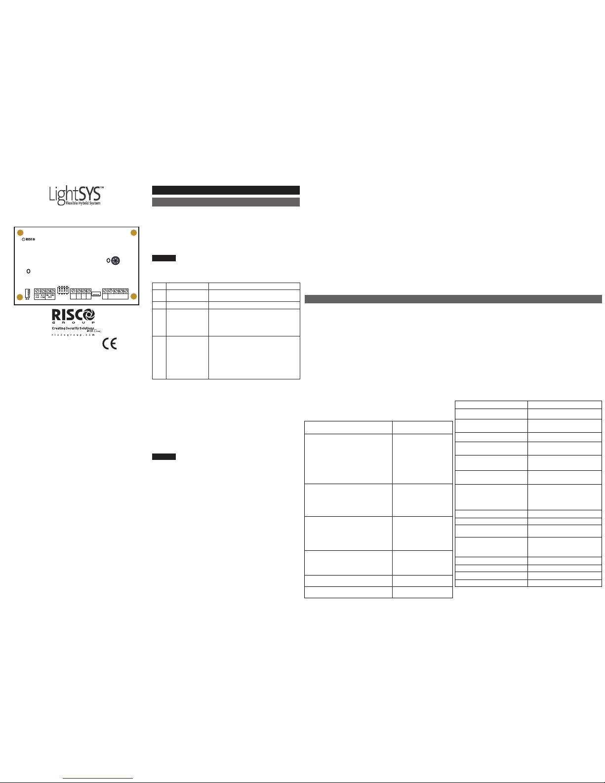
Dipswitches
SW Description Usage
1 Omit tamper Instead of a short with the TMP/COM
terminal block
2 OPT Not in use
3 Test Connected in parallel to all output
channels and enables to listen to all
played messages using a speaker (at
least 32 Ohm) connected between
the Test Spkr and COM terminals
4 Intern Mic Select an external or internal
microphone for recording messages:
On: Recording messages from the
microphone located on the Voice
module board.
Off: Recording messages from a
microphone located on Listen / Talk
unit (IN1 terminal)
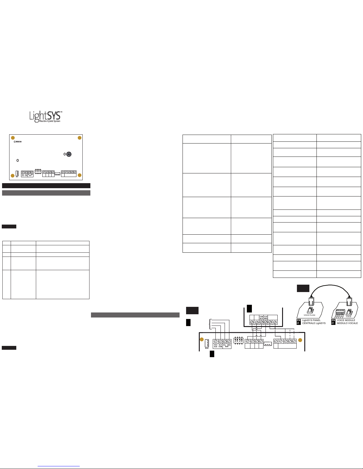
Wiring diagram (See Fig.1):
When connecting the Listen/Talk unit to the Voice module it is
recommended to use one of the two types of wires for the IN and
OUT connections:
● Independently shielded wires: Used for Electro-magnetically
Noisy Environment/Long Distance. The shield should be
grounded (connected to COM terminal block).
● Independently twisted pared wires: Used for Electro magnetically Unquiet Environment/Middle Distance. The second
wire should be grounded (connected to COM terminal block).
Other types of wires can be used for Electro-magnetically Silent
Environment/Short Distance.
NOTES:
● Do not run wires close to power (110/230 VAC), high-voltage
wiring or any communication lines.
● Do not wrap or roll wires.
● All unused wires should be grounded by connecting them to the
COM terminal.
● The maximum distance between each Listen/Talk unit and the
Voice Module should not exceed 150 meter.
LEDs Indication:
Power: The Power LED indicates the status of communication
between the Voice module and the Main Panel
Off: No voltage power from the main panel
On: There is normal communication with the Bus
Slow Flash: The LED starts to flash 15 seconds after
communication with the Bus is interrupted, or during
installation mode
Rec / Play: The Rec / Play Comm LED indicates the status of
communication between the Voice module and the remote
“Follow-Me” (FM) phone.
Condition Description
Off There is no communication with the FM number.
On FM communication has been established.
Slow Flash The Voice module is in the process of calling the
FM number.
Connectors
The Voice module board contains the following two connectors:
(See Fig.2)
● BUS (plug1): Used to connect the Voice module to the panel
via the 4-wire Bus. The AUX (RED), COM (BLK), BUS (YEL)
and BUS (GRN) terminals are identical to the BUS connector
and can be used for the same purpose.
● VOICE (plug2): Used to connect the Voice module to the
VOICE connector on the LightSYS Main Panel via the supplied
cable. This connector transmits signals from the Voice module
to the telephone line during remote communication, and is
essential for normal operation of the Voice module.
Technical Specifications
● Operating voltage: 13.8VDC +/-10%
● Current draw: 30 mA typical / 70 mA maximum
● Operating temperature: 0-70°C
● Main Panel Connection: wire BUS, ≤300 m from Main Panel
USER GUIDE
User Operation - Telephone Control
Commands
The LightSYS enables you to operate the system from a remote
touch-tone phone by initiating a telephone call to or from the
system and interacting with voice menus that guide you through
your required remote operation.
Receiving a call:
1. Pick up the phone.
2. Say “Hello” or press [#]. You will hear an event announcement
message.
3. Choose an option from the Acknowledgment menu.
Acknowledgment menu
Upon event occurrence, such as alarm activation, the system
informs you of security situations, for example, intrusion or fire,
by calling you and announcing a pre-recorded event announce-
ment message, followed by the Acknowledge menu.
After the Event Announcement message is made, the following
list of options is announced.
Operation Title: Action
Description
(remotely by telephone)
Acknowledge Message Press [1]
Acknowledging an event means that
you have received a message from
the security alarm system about a
relevant event in the system and
want to confirm this. After you
acknowledge an event, the system
calls the next FM number.
Acknowledge and stop all dialing Press [2] followed by
the code
This option acknowledges the event
and stops the system from calling the
next FM numbers to report the event.
Acknowledge and access the Press [3] followed by
Operations menu the code
The Operations menu lists the available
options for remotely operating your
system.
Listen In and Talk Press [6] [3] followed by
the code
This option enables you to perform bidirectional communication.
Repeat the event message Press [#]
Repeat the Acknowledge menu Press [*]
Calling the System:
1. Dial the number of the premises.
● If an answering machine is present at the premises: Let the line
ring once, hang up and call again.
● If an answering machine is not in use at the premises: Wait
until the system picks up. You will hear a continuous tone.
2. After the tones, enter the 2-digit remote access code.
3. Enter your user code followed by [#].
4. Choose your option from the Operations menu.
Operations Menu:
The Voice Operations menu announces options and instructions
on how to use the system functions. The options in the
Operations menu vary according to system status and your
access rights.
Following is a list of the remote operations options:
Operation description
Action (remotely by telephone)
Setting all partitions Press [1][1]
Setting a selected partition Press [1][9] followed by the
partition number
Unsetting all partitions Press [2][2]
Unsetting a selected Press [2][9] followed by the
partition partition number
Changing Zone Omit status Press [3] followed by the zone
number and then [#][9]
Operating Programming Press [4] followed by the output
Outputs
Changing Follow Me (FM) Press [5] followed by the FM
numbers
number and [#][2].
Enter the new phone number
and press [#][1].
Listen in to the premises Press [6][1]
Talking to the premises Press [6][2]
Listen and Talk to the Press [6][3]
premises
Recording messages that are
Press [7][1]… [5]
not included in the message
bank (5 messages)
Recording an opening message
Press [7][6]
Exiting the System Press [0]
To return to the previous menu Press [*]
To repeat the menu options Press [#]
ENGLISH
Voice Module
Model: RP432EV
© RISCO Group 05/2011 5IN1545 B
RISCO Group Limited Warranty
RISCO Group and its subsidiaries and affiliates ("Seller") warrants its products to
be free from defects in materials and workmanship under normal use for 24
months from the date of production. Because Seller does not install or connect the
product and because the product may be used in conjunction with products not
manufactured by the Seller, Seller cannot guarantee the performance of the
security system which uses this product. Seller's obligation and liability under this
warranty is expressly limited to repairing and replacing, at Seller's option, within a
reasonable time after the date of delivery, any product not meeting the
specifications. Seller makes no other warranty, expressed or implied, and makes
no warranty of merchantability or of fitness for any particular purpose.
In no case shall seller be liable for any consequential or incidental damages for
breach of this or any other warranty, expressed or implied, or upon any other basis
of liability whatsoever.
Seller's obligation under this warranty shall not include any transportation charges
or costs of installation or any liability for direct, indirect, or consequential damages
or delay.
Seller does not represent that its product may not be compromised or
circumvented; that the product will prevent any personal injury or property loss by
burglary, robbery, fire or otherwise; or that the product will in all cases provide
adequate warning or protection.
Buyer understands that a properly installed and maintained alarm may only
reduce the risk of burglary, robbery or fire without warning, but is not insurance or
a guaranty that such event will not occur or that there will be no personal injury or
property loss as a result thereof.
Consequently seller shall have no liability for any personal injury, property
damage or loss based on a claim that the product fails to give warning. However,
if seller is held liable, whether directly or indirectly, for any loss or damage arising
under this limited warranty or otherwise, regardless of cause or origin, seller's
maximum liability shall not exceed the purchase price of the product, which shall
be complete and exclusive remedy against seller.
No employee or representative of Seller is authorized to change this warranty in
any way or grant any other warranty.
WARNING: This product should be tested at least once a week.
UK Tel: 44-(0)-161-655-5500
support-uk@riscogroup.com
ITALY Tel: +39-02-66590054
support-it@riscogroup.com
SPAIN Tel: +34-91-490-2133
support-es@riscogroup.com
FRANCE Tel: +33-164-73-28-50
support-fr@riscogroup.com
BELGIUM Tel: +32-2522-7622
support-be@riscogroup.com
U.S.A Tel: +1-631-719-4400
support-usa@riscogroup.com
RISCO Group Contacting Info
RISCO Group is committed to customer service and product support.
You can contact us through our website (www.riscogroup.com) or at the
following telephone and fax numbers:
All rights reserved.
No part of this document may be reproduced in any form without prior
written permission from the publisher.
BRAZIL Tel: +55-11-3661-8767
support-br@riscogroup.com
CHINA (Shanghai)
Tel: +86-21-52-39-0066
support-cn@riscogroup.com
CHINA (Shenzhen)
Tel: +86-755-82789285
support-cn@riscogroup.com
POLAND Tel: +48-22-500-28-40
support-pl@riscogroup.com
ISRAEL Tel: +972-3-963-7777
support@riscogroup.com
(LED1)
MIC1
VOICE MODULE
Voice
(to panel)
Message Box
LED TMP
Out In1 In3In2
C
1 2 3 4
DIP SW1
Intrnl
MIC
OPT
Bypass
Tamper
Test
Rec
Play
COMAUX
Test
Spkr
(LED1)
MIC1
VOICE MODULE
Voice
(to panel)
Message Box
LED TMP
Out In1 In3In2
C
1 2 3 4
DIP SW1
Intrnl
MIC
OPT
Bypass
Tamper
Test
Rec
Play
COMAUX
Test
Spkr
GUIDA ALL'INSTALLAZIONE
Introduzione
Il modulo vocale fornisce informazioni audio circa lo stato di
funzionamento del sistema LightSYS e abilita qualsiasi telefono
remoto a toni (DTMF) a operare come una tastiera del sistema.
Al verificarsi di un evento nel sistema, come ad esempio una
condizione d’allarme, il modulo vocale informa l’utente circa la
condizione d’allarme evidenziando la tipologia dell’evento, ad
esempio rapina o intrusione.
NOTA:
Per la programmazione del modulo vocale, fare riferimento a
Manuale di Installazione e Programmazione della LightSYS.
Microinterruttori
Mic. Descrizione Utilizzo
1 Esclusione del
Esclude/Disabilita il morsetto TMP per
Tamper il collegamento del circuito tamper.
2 Opzionale Non utilizzato
3 Test Abilita ad ascoltare tutti i messaggi
utilizzando un altoparlante (almeno da
32 Ohm) collegato tra i morsetti Test
Spkr e COM.
4 Microfono Predispone il microfono interno
Interno o un microfono esterno per la
registrazione dei messaggi vocali:
On: Utilizza il microfono interno
(integrato) del modulo vocale per la
registrazione dei messaggi vocali.
Off: Utilizza il microfono di una unità
“Box Messaggi” per la registrazione
dei messaggi vocali
Schema di cablaggio (Vedi Fig.1):
Per il collegamento dei segnali audio IN e OUT è necessario
utilizzare cavi separati con le seguenti caratteristiche:
● Cavi indipendenti per i due segnali IN e OUT di ogni canale,
ognuno con il proprio schermo (1 cavo per il segnale IN ed un
altro cavo per il segnale OUT). Questi cavi sono adatti per
ambienti con possibili interferenze elettromagnetiche e/o per
lunghe distanze. Gli schermi dei cavi vanno messi a terra
tramite collegamento al morsetto COM.
Non connettere i segnali IN e OUT usando i conduttori dello
stesso cavo.
Altre tipologie di cavo vanno usate solo in ambienti privi di
interferenze e/o brevi distanze.
NOTE:
● Non passare i cavi audio vicino ai cavi della rete elettrica, ai
cavi di alta tensione, ai cavi utilizzati per le reti di computer o
altri cavi di comunicazione dati.
● Non arrotolare o avvolgere i cavi.
● Tutti i conduttori del cavo che non vengono usati e lo schermo
dei cavi devono essere messi a terra tramite collegamento al
morsetto negativo COM sia dalla parte del modulo vocale che
dal lato unità Box Messaggi.
● Il cavo che può essere usato per queste connessioni è un
normale cavo d’allarme schermato 2 x 0,22 con grado di
protezione 3. La sezione del cavo non è importante per la
connessione dei segnali audio.
● La distanza del cavo tra modulo vocale e ogni unità Box
Messaggi è al massimo di 150 metri.
La connessione tra modulo vocale e unità Box Messaggi deve
essere di tipo a stella ovvero tutti i cavi delle unità Box
Messaggi devono essere riportati al modulo vocale.
Indicazioni a LED
(LED1): Questo LED indica lo stato di comunicazione tra il
modulo vocale e la centrale come di seguito spiegato:
Spento: Il modulo Vocale non è alimentato.
Acceso: Normale comunicazione via Bus 485 con la
centrale LightSYS.
Lampeggiante: Il LED inizia a lampeggiare dopo 15
secondi dall’interruzione della comunicazione via bus 485
con la centrale oppure la centrale è in programmazione
tecnica.
Rec / Play: Questo LED indica la stato della comunicazione del
modulo vocale con i numeri telefonici per l’Utente “Seguimi FM”
come di seguito illustrato.
Condizione Descrizione
Spento Il modulo vocale non sta comunicando con
i numeri telefonici Seguimi FM.
Acceso Il modulo è in comunicazione con i numeri
telefonici Seguimi FM.
Lampeggiante Il modulo vocale sta effettuando la
chiamata telefonica ad un numero Seguimi FM.
Connettori
La scheda elettronica del modulo vocale ha due connettori ad
innesto di seguito elencati (Vedi Fig.2):
● BUS (Plug1): Permette il collegamento del modulo vocale al bus
485 della centrale LightSYS. La connessione al bus 485 della
centrale può anche essere effettuata tramite i morsetti del
modulo vocale AUX (RED), COM (BLK), BUS (YEL) e BUS
(GRN).
● VOICE (Plug2): Permette il collegamento del modulo vocale al
connettore VOICE situato sulla scheda elettronica della centrale
LightSYS. Il cavo per questa connessione è fornito con il
modulo vocale. Tramite questo connettore il modulo vocale
trasmette i segnali audio alla centrale che li inoltra sulla linea
telefonica per le operazioni di comunicazione remota con i
numeri telefonici Seguimi FM.
Caratteristiche Tecniche
● Tensione nominale di alimentazione: 13,8V— ±10%
● Assorbimento di corrente dalla rete elettica: 30 mA nominali /
70 mA max.
● Condizioni ambientali di funzionamento: 0-70°C
● Collegamento con la centrale: 4-fili BUS, cablaggio max. 300
metri.
GUIDA PER L'UTENTE
Operazioni remote di sistema
LightSYS consente di utilizzare il sistema da un telefono remoto
con tastiera a toni DTMF avviando una chiamata telefonica da o
verso il sistema e interagendo col menù vocale che vi guiderà
nelle operazioni da remoto.
Ricezione di Chiamate
1. Rispondere al telefono.
2. Dire “Pronto” o premere [#]. Il messaggio di allarme vi informa
della situazione.
3. Scegli una opzione dal Menù Acquisizione.
Menù Acquisizione
In caso di allarme, il sistema dà informazioni sulla situazione del
sistema di sicurezza (come un’intrusione o un incendio)
telefonando all’Utente e riproducendo dei messaggi di allarme
pre�registrati seguiti da un menù di Acquisizione.
Una volta trasmesso il messaggio di allarme, viene letta la
seguente lista di opzioni:
Operazione: Azione
Descrizione
(a distanza tramite telefono)
Acquisizione di un evento Premere [1]
Acquisire un evento significa
ricevere dal sistema un messaggio
di informazione su un evento
verificatosi e, successivamente,
confermare la ricezione. Dopo aver
acquisito l’evento, il sistema chiama
il successivo numero Seguimi (FM).
Acquisizione di un evento e Premere [2] seguito dal
interruzione di tutte le telefonate codice
Con questa opzione si consente
l’acquisizione dell’evento evitando
che il sistema chiami gli altri numeri
FM per informarli dell’evento
Acquisizione ed Accesso al menù Premere [3] seguito dal
Operazioni codice
Il menù Operazioni elenca le opzioni
disponibili per il funzionamento
remoto del sistema.
Ascolto e comunicazione in viva Premere [6] [3]
voce
Questa opzione permette di stabilire
una comunicazione bidirezionale.
Ripetizione del messaggio di Premere [#]
evento
Ripetizione del menù di Premere [*]
Acquisizione
Chiamata telefonica verso il sistema
1. Digitare il numero telefonico del luogo
● Se il sistema è collegato ad una linea telefonica analogica che
utilizza una segreteria telefonica, far squillare una volta e poi \
agganciare e richiamare dopo 10 secondi.
● Se non è in funzione una segreteria telefonica, attendere finché
il sistema non risponde alla chiamata. Il sistema risponde
emettendo un breve tono acustico.
2. Dopo il tono, inserire il codice di accesso a 2 cifre.
3. Digitare il codice utente e premere [#]. (codice predefinito = 1234)
4. Dopo che è stato accettato il codice inserito, si sentirà il
messaggio di stato del sistema, seguito dalla riproduzione del
menù Operazioni. Ora è possibile eseguire operazioni da
remoto.
ITALIANO
Menù Operazioni
Il menù Operazioni Vocali elenca dettagliatamente le opzioni
disponibili per il funzionamento remoto del sistema. Le opzioni
nel menù possono variare a seconda dello stato del sistema e
dei propri diritti di accesso.
Di seguito viene riportata una lista delle operazioni da remoto:
Descrizione dell’Operazione
Azione (a distanza tramite
telefono)
Inserimento di tutte le partizioni Premere [1][1]
Inserimento delle partizioni una Premere [1][9] seguito da Nº
per una Partizione
Disinserimento di tutte le Premere [2[2]
partizioni
Disinserimento delle partizioni Premere [2][9] seguito da Nº
una per una Partizione
Esclusione/reinclusione zona Premere [3]seguito da Nº Zona
seguito da [#][9]
Attivazione uscite di utilità Premere [4] seguito da Nº
Uscita
Modifica numeri telefonici FM
Premere [5] seguito da Nº FM o
[#][2]. Inserire nuovo numero di
telefono e premere [#][1].
Ascolto ambiente Premere [6][1]
Comunicazione in viva voce Premere [6][2]
Ascolto ambiente e Premere [6][3]
Comunicazione in viva voce
Registrazione di messaggi Premere [7][1] … [5]
personalizzati non inclusi nella
libreria di centrale (5 messaggi)
Registrazione di un messaggio Premere [7][6]
iniziale (comune)
Uscita dal sistema Premere [0]
Spostarsi nel livello precedente Premere [*]
del menù
Per ripetere le opzioni del menu
Premere [#]
EN BUS To Panel
IT BUS alla
Centrale
Voice
(to Panel)
Message Box
LED TMP
Out In1 In3In2
1 2 3 4
DIP SW1
Internl
MIC
OPT
Bypass
Tamper
Test
COMAUX
Test
Spkr
LED
TMP
AUDIO
OUT
IN
EN Listen/Talk Unit
IT Unità Box Messaggi
EN Voice Module
IT Modulo Vocale
VOICE PLUG4
VOICE
EN VOICE MODULE
IT MODULO VOCALE
EN LightSYS PANEL
IT CENTRALE LightSYS
TMP
LED
COM
AUX
Fig.2
Fig.1
Modulo Vocale
Model: RP432EV
 Loading...