

Risco iWISE QuadSEQ Grade 3 Installation Instructions Manual
Page 1
iWISE QUADSEQ Grade 3
The iWISE QUADSEQ Grade 3 is designed to meet DD243 requirements for sequential
confirmation and also meet PD6662, EN 50131-1 and EN50131-2-2
Grade 3 requirements.
The iWISE QUADSEQ Grade 3 includes built - in Triple EOL resistors for installation
simplicity, and active IR anti-masking for reliable detection of masking attempts.
iWISE QUADSEQ Grade 3 Main Features
iWISE QUADSEQ Grade 3
Installation Instructions
x PD6662, EN50131-1, EN50131-2-2 Grade 3
x Two PIR Detectors in a single housing with separate alarm outputs
x Two non-overlapping coverage patterns
x Coverage 12m
x Active IR Anti-Mask (up to 15cm)
x Built-in Triple EOL resistors, jumper selectable
x Wall and Cover tampers
x Opto - relays for low current consumption and long life time
x Remote and Local Self Test
x LED control input
x LED control polarity Jumpers
x 3 LEDs for easy walk test
x True Temperature Compensation
x Wall tamper proof swivel (optional)
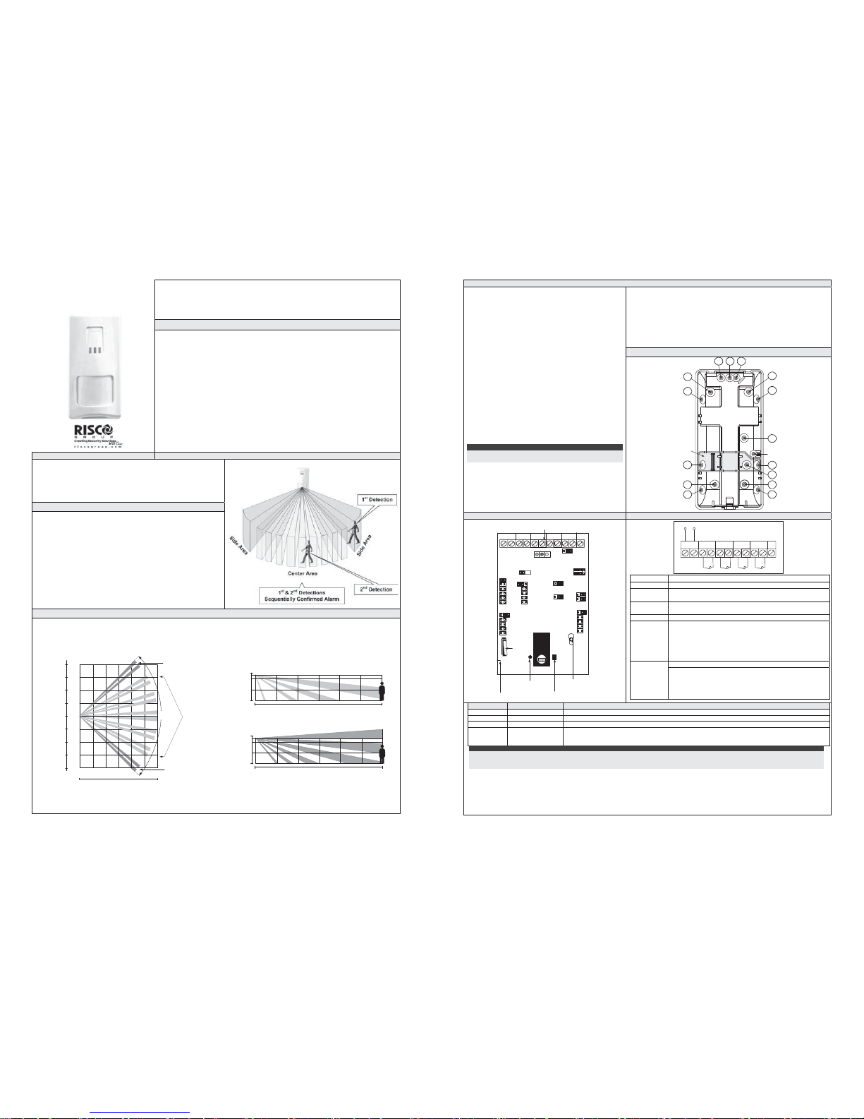
Principle of Operation 3D Image of the Application
The unit contains two independent detectors in a single housing. When
mounted in the corner of a room, one detector covers the two walls
(side area), while the second detector covers the center of the room.
When an intruder enters the room via a door or window, the side area
triggers. When the intruder then moves to the center of the room, the
second detector triggers, providing a sequentially confirmed alarm.
Installation Considerations
x Before installing, study the space to be protected carefully in order to
choose the exact location of the unit for the best possible coverage.
x Corner installation is recommended. The detection side areas
(which are two curtain zones at 80° to each other), should cover the
room walls, and therefore any vulnerable doors and windows.
x The additional internal PIR detector covers the center area of the
room. Recommended mounting height is 2.4m.
x Avoid installations where rotating machines (e.g. fans) are normally
in operation within the coverage pattern. Do not mount the detector
in direct sunlight or near any heat sources. Point the unit away from
glass exposed to the outdoors and objects that may change
temperature rapidly.
x The installation surface should be solid, smooth and vibration free.
Coverage
0m 2 4 6 8 10 12m
90
0
Top View
0m
2
4
6
8
2
4
6
8
Side Area
Center Area
Side Area
Side View - Center Area
0m 2 4 6 8 10 12m
0m
2
2.4m
Side View - Side Area
0m 2 4 6 8 10 12m
0m
2
2.4m
Page 2
Installation
8. Seal the remaining holes with a sealant compound.
9. Reinstall the PCB into its desired position.
10. Wire terminal (see Terminal Wiring section)
11. Set jumpers (see Jumper Settings section).
12. Install the front cover back to its place (in a reverse sequence of the
removal).
13. Reapply electrical power to the detector for correct AM calibration.
Recalibrate after every successive removal of cover.
14. Perform a Walk test (see Walk Test section).
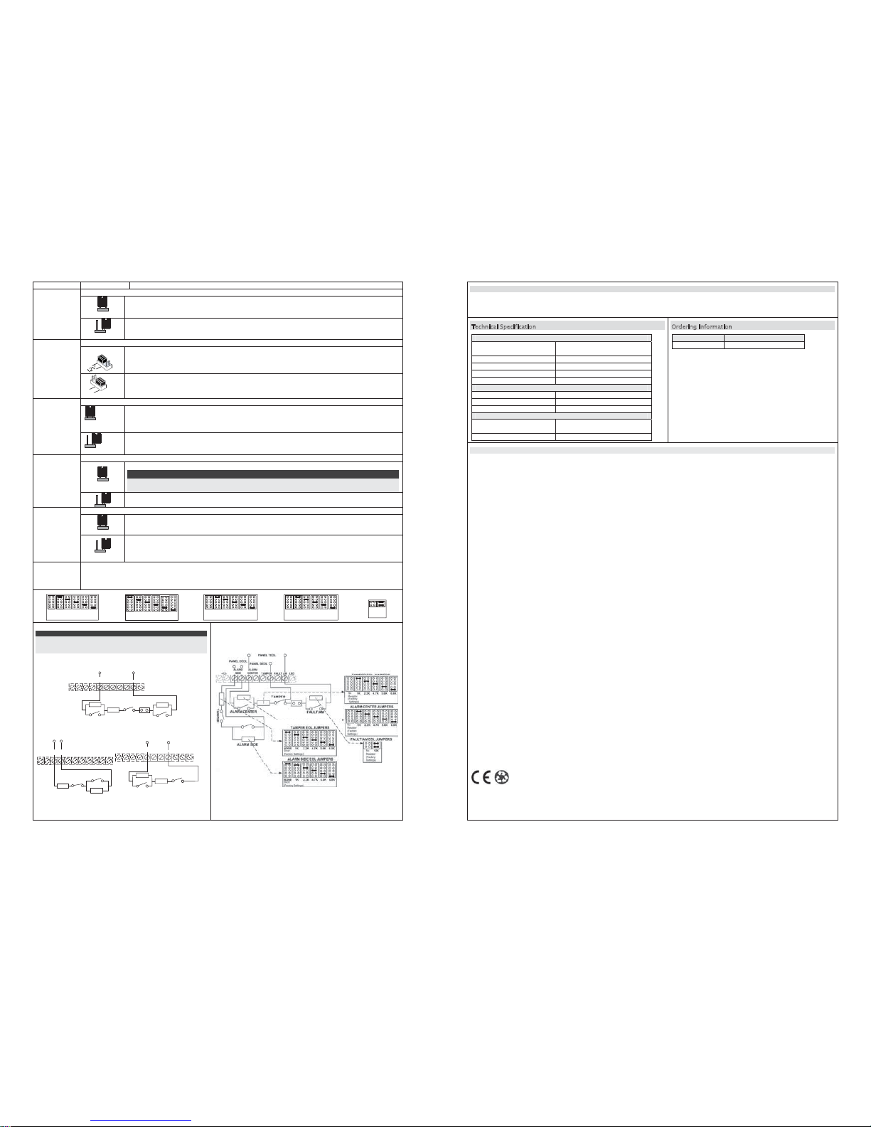
Back Plate Knockouts
1. To open the front cover:
x Turn the front cover locking screw counter-
clockwise.
x Insert a screwdriver through the dedicated slot/s to
open the detector's front cover.
2. Loosen the PCB holding screw, located on the right
hand side of the PCB and slide the PCB down until the
screw reaches the widened opening. Lift the PCB up to
remove.
3. Mounting - iWISE QUADSEQ Grade 3
can be mounted
either on a flat surface or on a wall corner (corner
mounting).
x Using a suitable tool, open the following
knockouts on the detector’s base.
x A1, A2 and A3: External cables knockouts (open
out at least one wiring knockout)
x A4, A6, A9, A12, and A15: Wall mounting
knockouts
x When using a swivel adapter use the A4, A6, and
A15 openings to connect the detector to the
swivel adapter.
x A5 and A10: Right corner mounting knockouts
x A11 and, A14: Left corner mounting knockouts
Note:
The A7, A8 AND A13 knockouts are not to be used in this
configuration.
4. Use the base as a template for marking the installation
holes (mark through the mounting holes).
5. Put the base in a safe place, drill the required holes in
the surface or in the corner, and insert anchors (if
necessary).
6. Insert external cables through the cable hole/holes.
7. Mount the rear cover in its final location.
Range
Adjustment
Bolt Thread
A1 A2 A3
A6
A7
A8
A9
A10
A12
A11
A13
A4
A5
A15
A14
Back tamper
“Breakable” plate
PCB View Terminal Wiring/Outputs Activation
Tamper
Switch
Range
Adjustment
Screw
Terminal
Block
Active IR
Anti-Mask Receiver
FAULT/AM
TAMPER
-12 +
LED
ALARM
SIDE
LEDS
LONG
ALARM
Active IR
Anti-Mask Transmitter
Range Scale
Mark
ALARM
CENTER
TAMPER EOL
LED
INPUT
2.2K
1K
4.7K
5.6K
6.8K
LEDS
SIDE
FAULT/AM
CENTER
ALARM CENTER
ON
SENSITIVITY
HIGH LOW
0V
12K
SHORT
AM E.O.L
SELF TEST
LOC REM
INT EXT
CONF
12V
2.2K
1K
4.7K
5.6K
6.8K
2.2K
1K
4.7K
5.6K
6.8K
NONE
OFF
SIDE
TAMPER
(upper) EOL
FAULT/AMTAMPER
12VDC
LED
ALARM
SIDE
ALARM
CENTER
+ -
Terminal Description
- 12 +
12VDC Input
ALARM
SIDE
Normally closed output
ALARM
CENTER
Normally closed output
TAMPER
Normally closed output
FAULT/AM
Normally closed output
The FAULT/AM output opens in the following events:
x Detector is masked (Alarm Side and Alarm Center
also open in this case)
x Self test failed
x Input voltage is low (6VDC - 8VDC)
See LED INPUT jumper for settings
LED
When an activation signal is applied to the LED input of the
terminal block, LEDs will be disabled (see also Self Test in
Jumper Settings table).
LEDs are enabled if nothing is connected (unless LED jumper
is OFF).
LED State Description
Yellow On Center Area PIR detection
Green On Side Area PIR detection
Red Flashing Fault / Anti Masking detection ***
All LEDs
Flashing
(One after another)
At Power - up, the LEDs will blink continuously, one after the other, until the end of the warm-up period (2-3 minutes).
At the end of power-up period the RED LED will continue to flash until the end of AM calibration.
Important: Always close the front cover prior to applying power, for correct AM calibration.
Notes:
* To enable LED indications, the LED jumper has to be in ON position and no signal is attached to the LED terminal.
** When an activation signal (see LED Activation jumper for settings) is applied to the LED input of the terminal block, LEDs will be disabled.
*** AM indication continues until masking is removed, and during power up AM calibration.
Page 3
Jumper Position Function
Used to determine the sensitivity of the center PIR area.
HighHigh Sensitivity selection
SENSITIVITY
(Default)
Low: Low Sensitivity selection
Used to determine the polarity of the external input.
(Default)
12V: 12v has to be connected in order to disable the LED’s.
GND or N.C. has no influence on the LED’s status. (see self test jumper configuration)
LED INPUT
0
V
0V: The GND has to be connected in order to disable the LED’s.
12v or N.C. has no influence on the LED’s status. (see self test jumper configuration)
Used to determine the relay’s activation logic.
INT: The detector’s alarm activation is determined by the detector’s internal logic. Intruder detection on
one of the PIR’S detection areas (side or center) activates the appropriate LED only.
If both PIR’S (side and center) are triggered within a time window of 2 minutes, then both side and
center relays are activated
CONF
(Default)
EXT: The security panel determines the detector’s alarm activation. Intruder detection on one of the
detection zones (side or center) activates the appropriate LED and Relay only.
Used to determine the operation of the detector’s LEDs
(Default)
ON: LEDs are enabled
Note:
When an activation signal (see LED Activation jumper for settings) is applied to the LED input of the
terminal block, LEDs will be disabled.
LED
OFF: LEDs are disabled
Used to test the PIR channels functionality
LOC (Local Self Test): If there is no alarm detection within 1 hour from previous detection, the detector
will self test both PIR channels.
In case the local self test fails, the FAULT/AM Relay is activated for a period of 2.5 seconds.
SELF TEST
(Default)
REM (Remote Self Test): Remote Self Test is activated when the LED terminal input is switched from
DISABLE to ENABLE mode (see LED Activation jumper for settings).
In case the remote self test passes, the Alarm Relays are activated for a period of 5 seconds.
In case the test fails, FAULT/AM Relay is activated for a period of 2.5 seconds.
EOL
RESISTORS
JUMPERS
The jumpers are used when connecting the detector to a DEOL or TEOL Zone. The jumpers allow the selection of
TAMPER, TAMPER (upper), ALARM CENTER and ALARM SIDE E.O.L resistors (1K, 2.2K, 4.7K, 5.6K or 6.8K),
according to the control panel. An additional double jumper allows the connection of 12K FAULT/AM E.O.L resistor (see
EOL Resistors Scheme).
TAMPER EOL JUMPERS
1K
No
Resistor
(Default)
2.2K 4.7K 5.6K 6.8K
TAMPER (upper) EOL JUMPERS
1K
Short
(Default)
2.2K 4.7K 5.6K 6.8KNONE
ALARM CENTER JUMPERS
1K
No
Resistor
(Default)
2.2K 4.7K 5.6K 6.8K
ALARM SIDE EOL JUMPERS
1K
No
Resistor
(Default)
2.2K 4.7K 5.6K 6 .8K
FAULT/AM EOL
JUMPERS
12K
No
Resistor
(Default)
EOL Resistors Scheme
Note:
Side & Center area can be connected to DEOL or
TEOL areas on the panel as illustrated below.
TAMPER
ALARM
CENTER
ALARM
SIDE
TAMPER+12- LED
FAULT/AM
TEOL ZONE
FAULT AM
ALARM
CENTER
+12- LED
ALARM SIDE
TAMPER FAULT AM
TAMPER
DEOL/TEOL
ZONE
ALARM SIDE
ALARM
CENTER
TAMPER
ALARM
CENTER
+12-
FAULT AM
LED
DEOL ZONE
ALARM
SIDE
TAMPER
ALARM
CENTER
Page 4
Walk Test
Two minutes after applying power (warm-up period), walk test the Detector over the entire protected area to verify proper operation of the
unit.
Important: Always close the front cover prior to applying power to the detector.]
7HFKQLFDO6SHFLILFDWLRQ
Electrical
Current consumption 12mA at 12VDC, 39mA at
12VDC (max. with all LEDs ON)
Voltage requirements 9 -16VDC
Alarm contacts 24VDC, 0.1A
Tamper contacts 24VDC, 0.1A
FAULT/AM contacts 24VDC, 0.1A
Environmental
RF immunity According to EN50130-4
Operating temperature -20°C to 55°C (-4°F to 130°F)
Storage temperature -20°C to 60°C (-4°F to 140°F)
Physical
Size 127.6 x 64.2 x 46.6 mm
(5 x 2.5 x 1.84 in.)
Weight 115 gr. (4 oz)
2UGHULQJ,QIRUPDWLRQ
Part Number Description
RK800QS0000A iWISE QUADSEQ Grade 3
RISCO Group Warranty
RISCO Group and its subsidiaries and affiliates ("Seller") warrants its products to be free from defects in materials and workmanship under normal use for 24
months from the date of production. Because Seller does not install or connect the product and because the product may be used in conjunction with products
not manufactured by the Seller, Seller cannot guarantee the performance of the security system which uses this product. Seller's obligation and liability under
this warranty is expressly limited to repairing and replacing, at Sellers option, within a reasonable time after the date of delivery, any product not meeting the
specifications. Seller makes no other warranty, expressed or implied, and makes no warranty of merchantability or of fitness for any particular purpose.
In no case shall seller be liable for any consequential or incidental damages for breach of this or any other warranty, expressed or implied, or upon any other
basis of liability whatsoever.
Seller's obligation under this warranty shall not include any transportation charges or costs of installation or any liability for direct, indirect, or consequential
damages or delay.
Seller does not represent that its product may not be compromised or circumvented; that the product will prevent any persona; injury or property loss by
burglary, robbery, fire or otherwise; or that the product will in all cases provide adequate warning or protection. Buyer understands that a properly installed and
maintained alarm may only reduce the risk of burglary, robbery or fire without warning, but is not assurance or a guarantee that such will not occur or that there
will be no personal injury or property loss as a result.
Consequently seller shall have no liability for any personal injury, property damage or loss based on a claim that the product fails to give warning. However, if
seller is held liable, whether directly or indirectly, for any loss or damage arising from under this limited warranty or otherwise, regardless of cause or origin,
sellers maximum liability shall not exceed the purchase price of the product, which shall be complete and exclusive remedy against seller. No employee or
representative of Seller is authorized to change this warranty in any way or grant any other warranty.
United Kingdom
Tel: +44-161-655-5500
technical@riscogroup.co.uk
Italy
Tel: +39-02-66590054
support@riscogroup.it
Spain
Tel: +34-91-490-2133
support-es@riscogroup.com
France
Tel: +33-164-73-28-50
support-fr@riscogroup.com
Belgium
Tel: +32-2522-7622
support-be@riscogroup.com
USA
Tel: +305-592-3820
support-usa@riscogroup.com
Brazil
Tel: +55-11-3661-8767
support-br@riscogroup.com
China
Tel: +86-21-52-39-0066
support-cn@riscogroup.com
Poland
Tel: +48-22-500-28-40
support-pl@riscogroup.com
Israel
Tel: +972-3-963-7777
support@riscogroup.com
PD6662, EN50131-1, EN50131-2-2 Grade 3 Class II
© RISCO Group 12/08 5IN800QS B
 Loading...