


GG
GG
TT
TT
44
44
99
99
00
00
XX
XX
CC
CC
oo
oo
nn
nntttt
rr
rr
oo
oollll
PP
PP
aa
aa
nn
nn
ee
eellll
User Instructions
Your local installer: www.eaglesecuritysolutions.co.uk


Contents
User Information ......................................................... 2
Introduction ................................................................... 3
User Code Types.......................................................... 3
Setting The System ...................................................... 4
Setting The System via a Radio Fob ............................ 5
Setting & Unsetting via Keyswitch ................................ 5
Unsetting The System .................................................. 6
Part Setting The System............................................... 6 - 7
Removing Zones........................................................... 8
Testing The System...................................................... 9
Viewing The Event Log................................................. 10 - 11
Changing The Chime Status......................................... 11 - 12
Programming User Codes ............................................ 13 - 15
Programming Time & Date ........................................... 16
Vo-Comm Introduction.................................................. 17
Vo-Comm Programming ............................................... 17 - 19
Using Vo-Comm ........................................................... 20
Messages from Vo-Comm ............................................ 20
User Initiating Remote Access ..................................... 21
Resetting After An Alarm .............................................. 22 - 23
Setting Engineer Authorisation ..................................... 25
G-Tag Introduction........................................................ 27
Programming G-Tag ..................................................... 27
Using G-Tag ................................................................. 27
Display Status Blanking ................................................ 28
Keypad Tamper ............................................................ 28
Keypad Alert ................................................................. 28
System Tampers........................................................... 28
Mains Failure ................................................................ 29
Setting The System With Mains Fail............................. 29 - 30
Re-setting The Display After A Mains Fail .................... 30
Advanced Code Programming...................................... 31
Using Advanced Codes ................................................ 31
End User Training......................................................... 32
Testing / Servicing Your System................................... 32
System Attributes.......................................................... 35
Service Record ............................................................. 36
User Chart .................................................................... 37
Page 1
GT490X
User Manual

Page 2
User Manual
GT490X
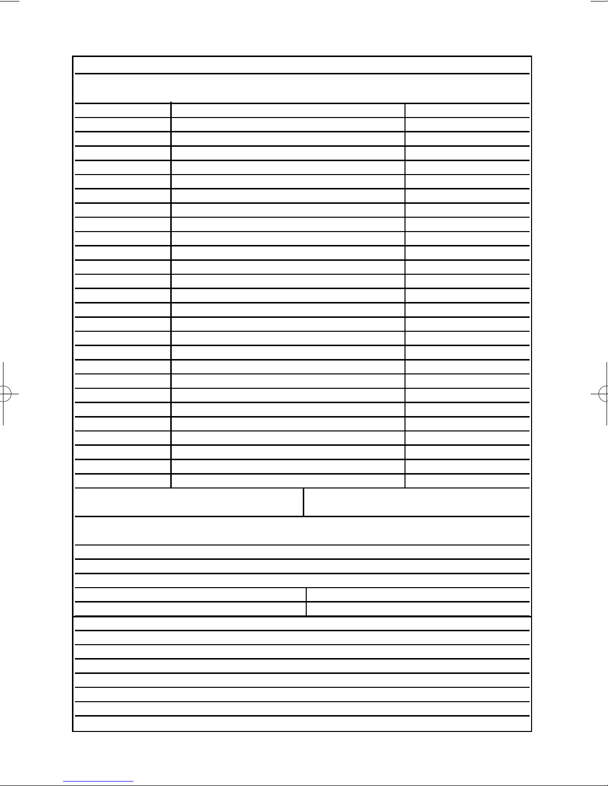
User Information
Customer Name:-
Customer Address:-
Control Panel Model GT490X
No of Keypads
Keypad 1 Location
Keypad 2 Location
Keypad 3 Location
Keypad 4 Location
G-Tag 1 Location
G-Tag 2 Location
Keyswitch Location (if fitted) Reserved User Code User No.
Installation Company Name:-
Installation Company Address:-
Installation Company Tel. Fax.
Other Information:-
Note: This section to completed by the installation engineer

Page 3
GT490X
User Manual
Introduction
The GT490X Control Panel is a microprocessor based unit with multiple user and
engineer programmable options. Control of the system is via LCD Remote Keypad
(RKP) giving two rows of 16 character English text. Facility is provided (model
dependant) for Central Station and/or Vo-Comm (message communication) to inform
of system status and alarm events. Vo-Comm messages may be sent to standard land
line telephones or mobile telephones.
Please take time to familiarise yourself with the type of equipment fitted to your
premises as it will prove invaluable whilst using this manual. Your installation company
will give training on the use of the equipment in order to comply with the relevant
standards and will be able to answer specific questions about your system, request for
additional or new staff training should be directed to your installation company.
If the Control Panel is non
EN then all displays will be shown and
“ENTER CODE CHECK” will not be displayed.
All information displays will remain until cleared by the User.
User Code Types
Master Level User Code BS / EN2 (default) - 5678
Five Levels of User Codes are available on the GT490X each user code type allows
for different levels of access. In total 15 User codes may be programmed by a Master
Level User Code.
User number 1 will always be a Master Level User but the remaining 14 User Codes
may be programmed (by a Master Code) to the required level of access. These may be
changed at any time via a Master level code. The User Code levels available and the
functions available for the levels are:-
Master Allows Setting, Unsetting, Zone Remove (if programmed by
(User 1 will always engineer), Test System, View Log, Chime On/Off, User
be Master Level) Codes, Set Time/Date, Reset After Alarm (if programmed
by engineer), Unsetting.
Control Allows an output that has been pre-programmed by the
installation company to be operated. May have the attribute
of Can / Cant Unset. May never Set a system
(Refer to Advanced Code Programming for details)
Set Only Only Allows for the setting of the system.
Main User Allows Setting, Part Setting, Zone Remove (if programmed
by engineer), System Test, Unsetting, Reset after Alarm (if
programmed by engineer).
User Allows Setting, Part Setting, Reset after Alarm (if
programmed by engineer), Unsetting.
IMPORTANT USER INFORMATION
Page 4
GT490XUser Manual
Setting The System
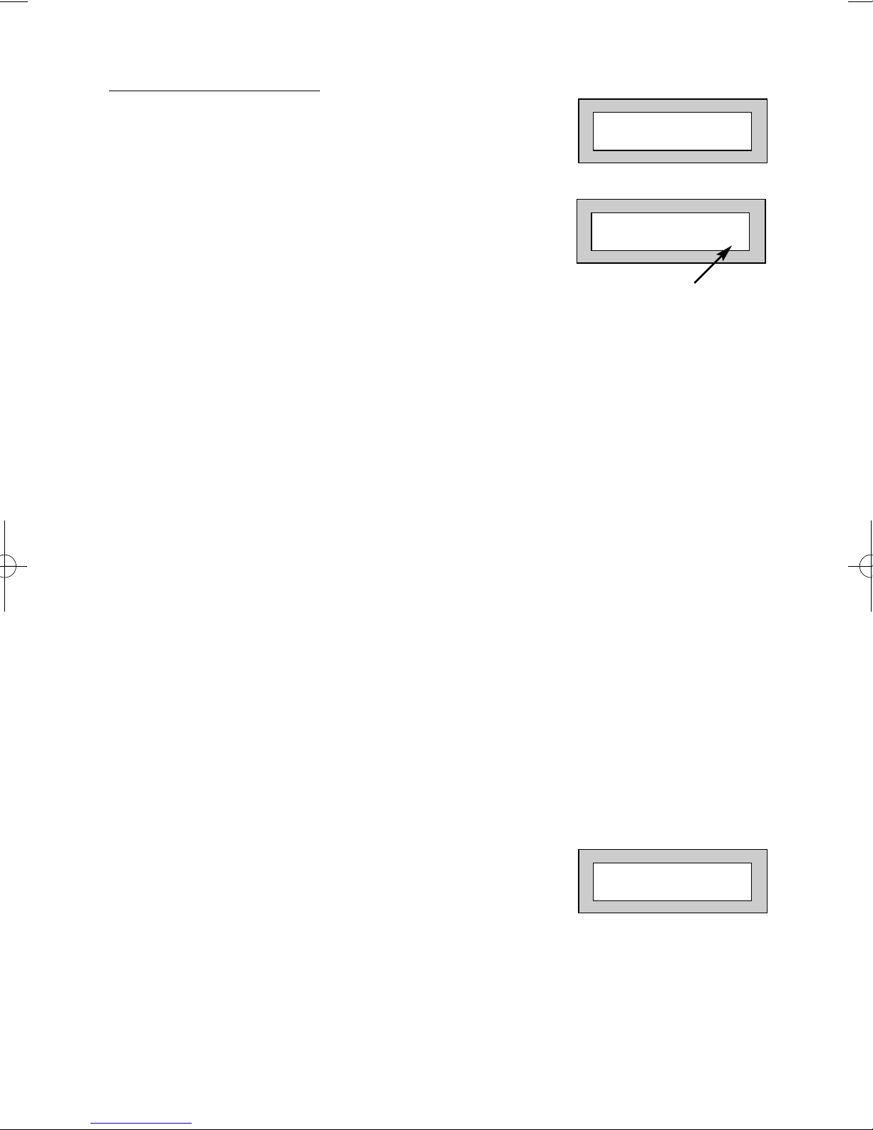
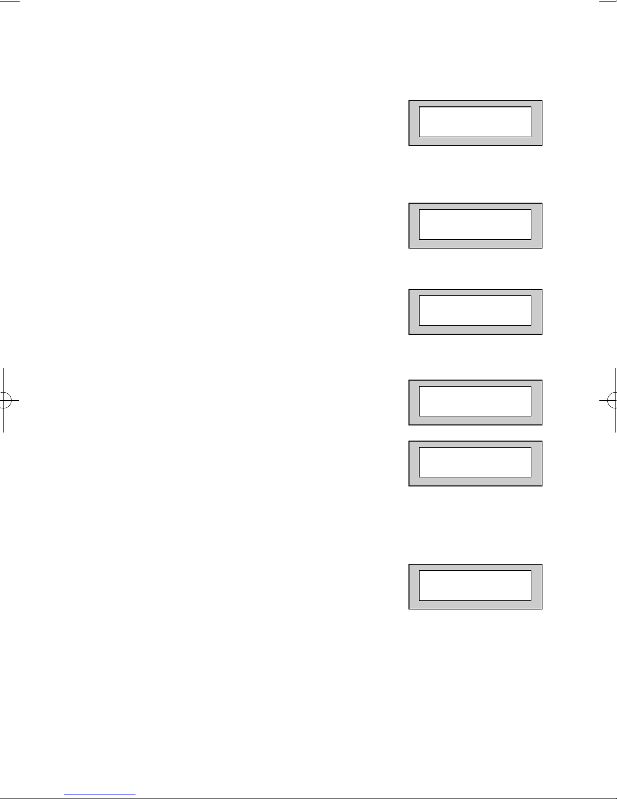
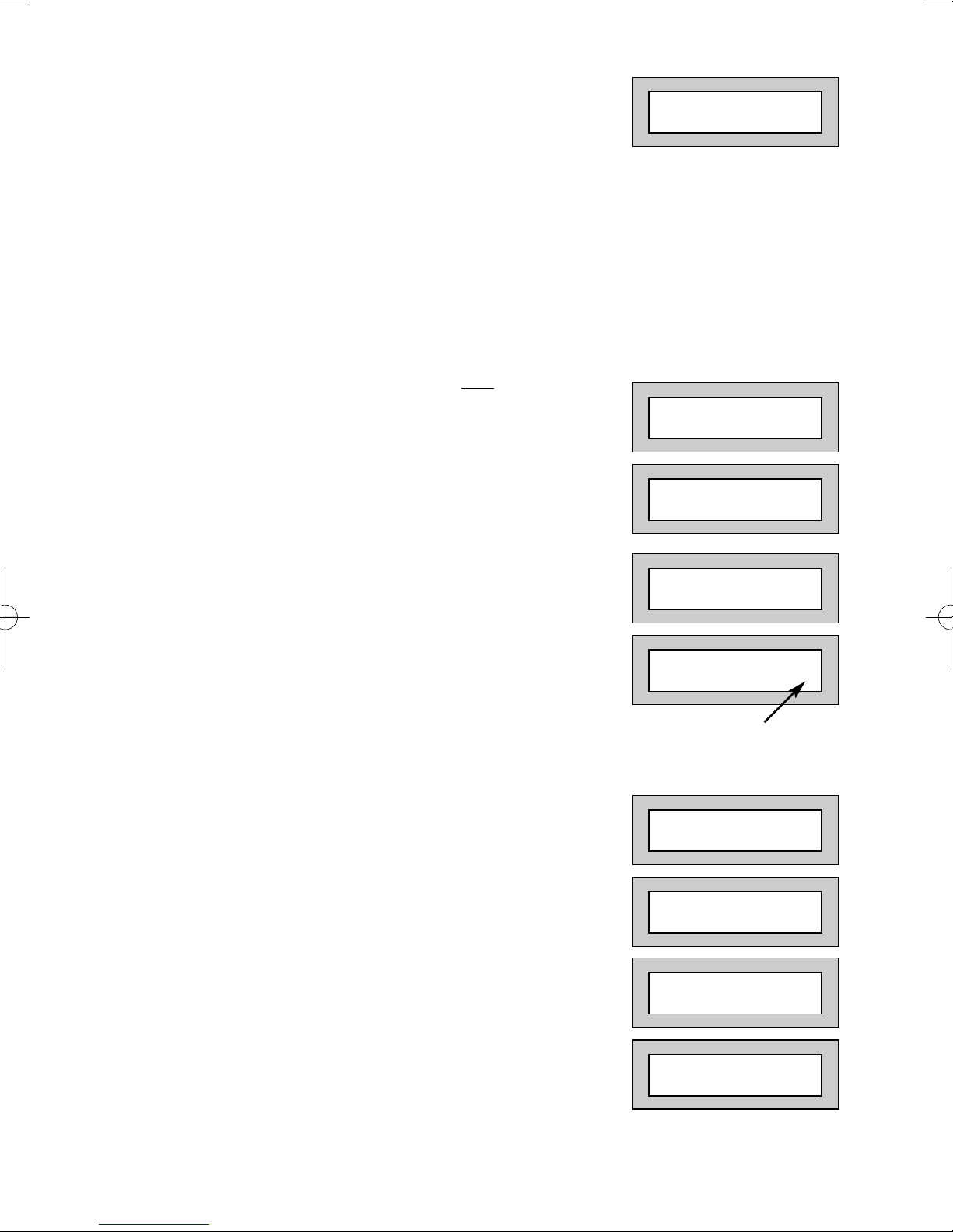
1) With the display showing:-
2) Enter your User code.
(Followed by YES if a Master or Main type code
has been used). The display will show:and a continuous exit tone will sound.
Note: Count down in display is dependant on the setting mode
programmed by the Engineer.
3) Exit the premises via the authorised exit route
(the exit tone will change if any detectors are violated during exit).
4) Once the premises are secure listen, (from outside
the protected area) that the exit tone returns to the
continuous tone.
5) Wait until the exit tone finishes before leaving.
Note: If enabled by the engineer, pressing the Quick key during exit time will
shorten exit time to 3 seconds.
Note: G-Tag Proximity Tags may be used for setting and unsetting the
system. Please refer to the Using G-Tag section for instructions.
Note: Depending on the level of your system and the legislation that it is
required to comply with your installation company may have initialised
Display Blanking. When this is used the Status of the system will only
be indicated on the display for ten seconds after it has been Set and for
ten seconds after it has been Unset.
Setting if a Zone has been put on test
If a zone has been put on test, and the system is to be Set /
Part Set / Area Set, the display will show:and a warning tone will sound.
If you wish to set the system press NO to continue.
Note: If you are unaware that a zone has been put on test contact
your installation company.
01 JAN 18 : 58 : 01
EXIT Now !
All Zones ON 15
Time will count down
Zone/s On Test
NO to Continue

Pre Exit Check
At the start of the setting procedure any non exit routes that
are open will show a fault tone. The display will show, for
example:If the fault clears within 20 seconds then the exit will begin,
otherwise the display will return to Day (Unset) Mode.
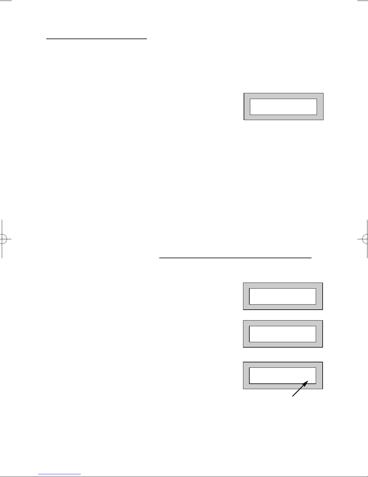
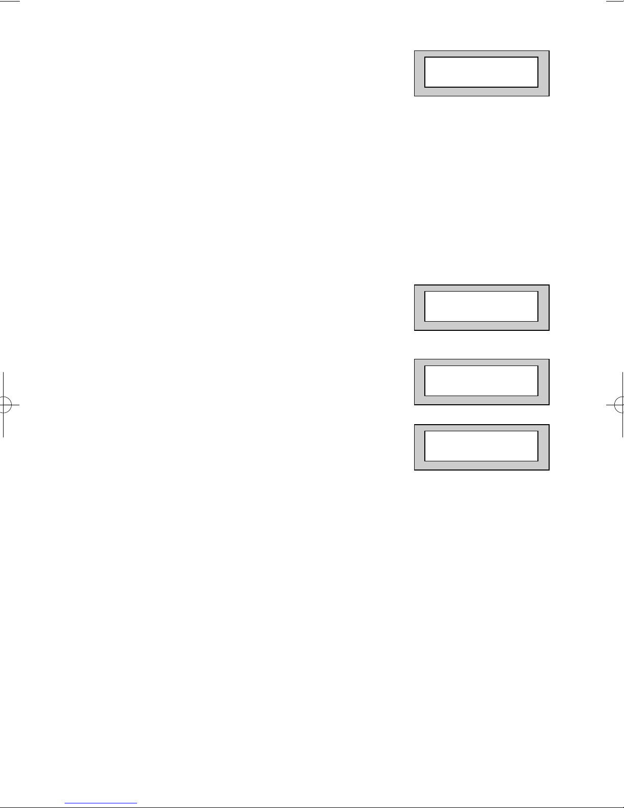
Setting the System via a Radio Fob (Monitored Systems Only)
Setting a monitored system with a radio fob requires interaction with the keypad.
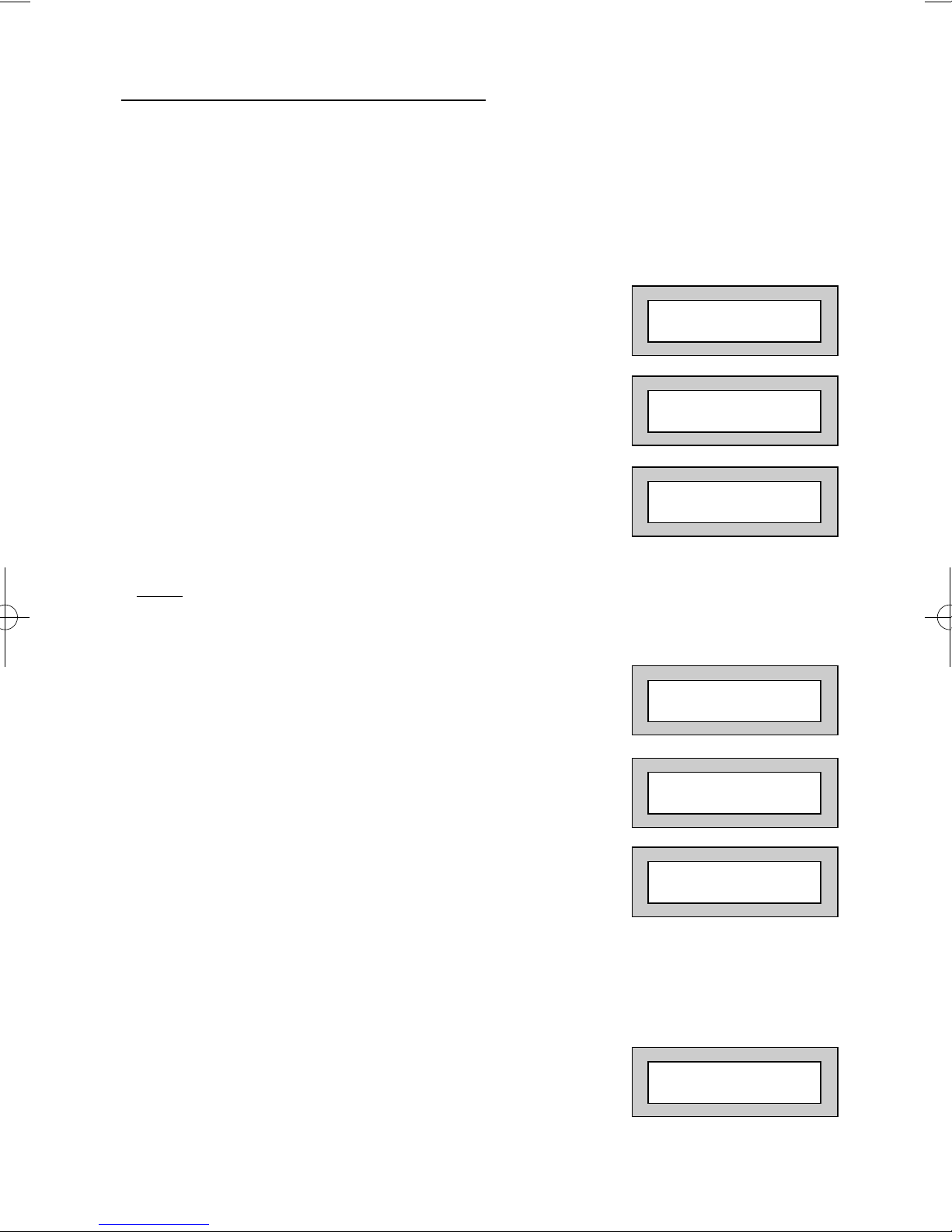
1) When the lock button is pressed on the fob the
display will show:-
2) Press Yes. The system will start to set.
Note: If the No key is pressed or you take longer than 20 seconds the display
will return to the time and date.
Setting & Unsetting the System via a Keyswitch (if fitted)
One of two types of keyswitch(es) may have been fitted to your system.
Normal
To set the system with a normal keyswitch, insert the key and turn to the ON position
then remove the key. Follow the instructions from step 3 (above).
To unset, insert the key and turn to the OFF position.
Biased
To set the system with a biased keyswitch, insert the key and turn it then return the key
to the original position and remove. Follow the instructions from step 3 (above).
To unset, repeat this operation.
Page 5
GT490X
User Manual
Zone 8 12hr
Can’t Set ! Check
Press YES to Set
Page 6
GT490X
User Manual
Unsetting The System
1) Enter the premises via the authorised entry route
(the broken entry tone will sound),
proceed to the keypad.
2) At the keypad enter a valid code, the display
will show:-
3) The system is now unset.
Note: G-Tag Proximity Tags may be used for setting and unsetting the
system. Please refer to the Using G-Tag section for instructions.
Part Setting The System (using Master & Main type codes)
1) With the display showing:-
2) Enter a Master or Main type code, the
display will show for example:-
3) Press 1, 2 or 3 (for Part 1, 2 or 3), the
display will show for example:-
Note: Your installation company will have
informed you what zones are being removed
(omitted) for the Part Set you are using. Refer
to the System Attributes section for what zones
have been programmed as Part Set zones.
01 JAN 18 : 58 : 01
01 JAN 18 : 58 : 01
Do you want to . .
SET the System ?
EXIT!
Part 1 15
Time will count down

Page 7
GT490X
User Manual
4) The exit tone may or may not be heard
depending on the system settings programmed
by the installation company.
5) Exit the premises or retire to an unprotected
part of the system. At the end of the exit time
either the exit sounder will stop, (if the exit tone has
been audible) or a single beep will be emitted (if the
exit tone has been silent).
6) The system is now Part Set, you are free to move
around the zones that have been removed by the
Part Set, but other zones on the system are
active.

Page 8
GT490X
User Manual
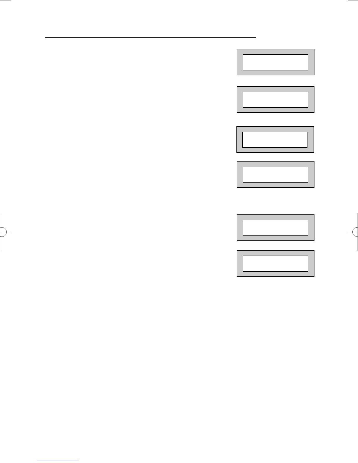
Removing Zones When Setting (Master & Main codes only)
If programmed by the installation company, individual zones may be removed (omitted)
when the system is set, this may only be done by a Master or Main level of code.
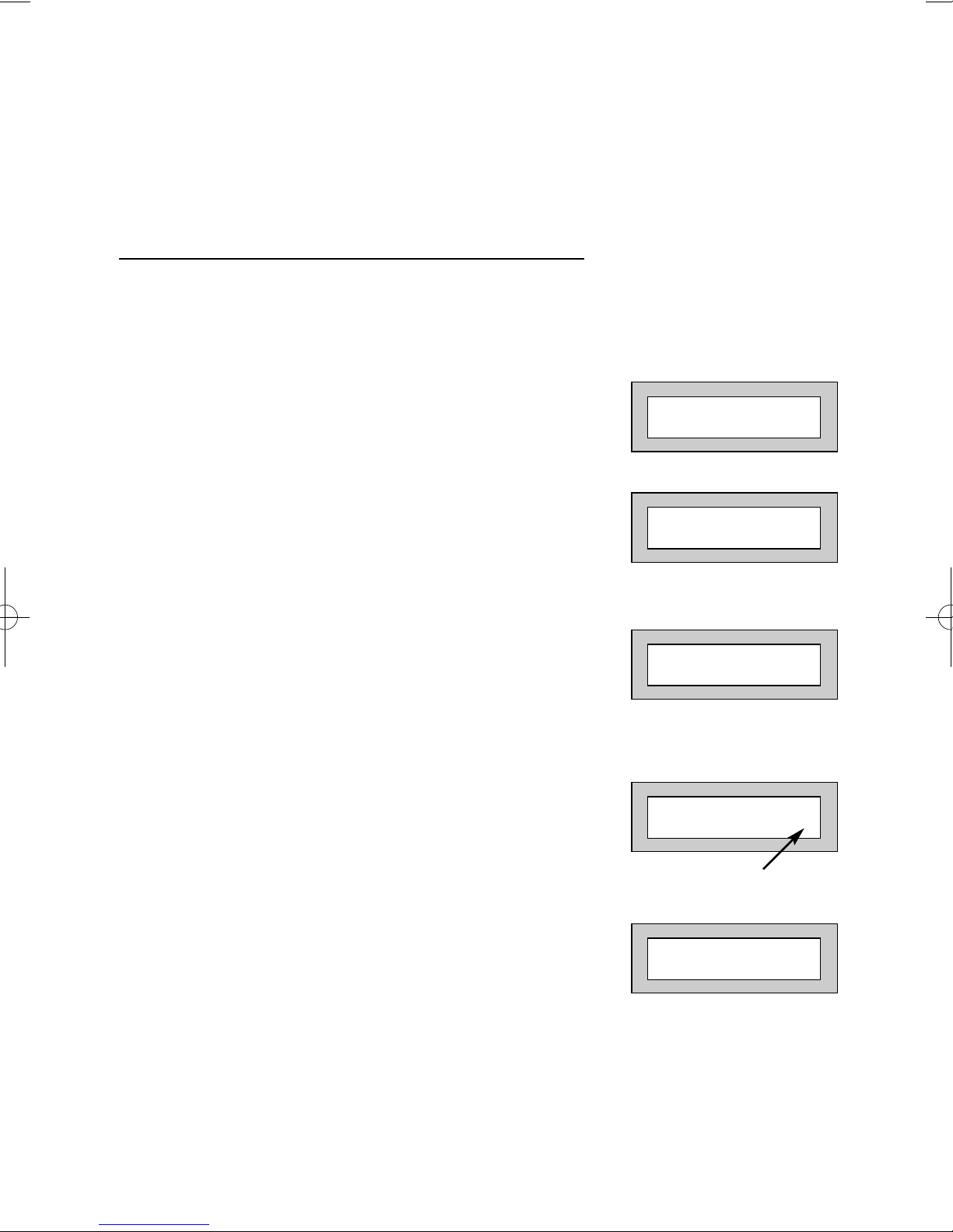
1) With the display showing:-
2) Enter a Master or Main level code,
the display will show:-
3) Press NO, the display will show:-
4) Press YES, the display will show:-
5) Enter the zone number you wish to
remove followed by YES. (pressing
NO will 'un-remove' a zone). The
display will show:-
6) Repeat step 5 until you have removed all
the required zones.
7) Press 0 to escape, the display will show:-
8) Press YES, the continuous exit tone will
sound.
9) Exit the premises via the authorised
exit route ( the exit tone will change as detectors
are violated). When the premises are secure
listen that the exit tone returns to the continuous
tone. Wait until the exit tone finishes before leaving.
Note: Zone remove is only effective for the one set.
01 JAN 18 : 58 : 01
Do you want to . .
SET the System ?
Do you want to . .
SET the System ?
Do you want to . .
REMOVE Zones ?
Enter Zone # - - then +Yes or -No
Enter Zone # - - then + YES or - NO
Page 9
GT490X
User Manual
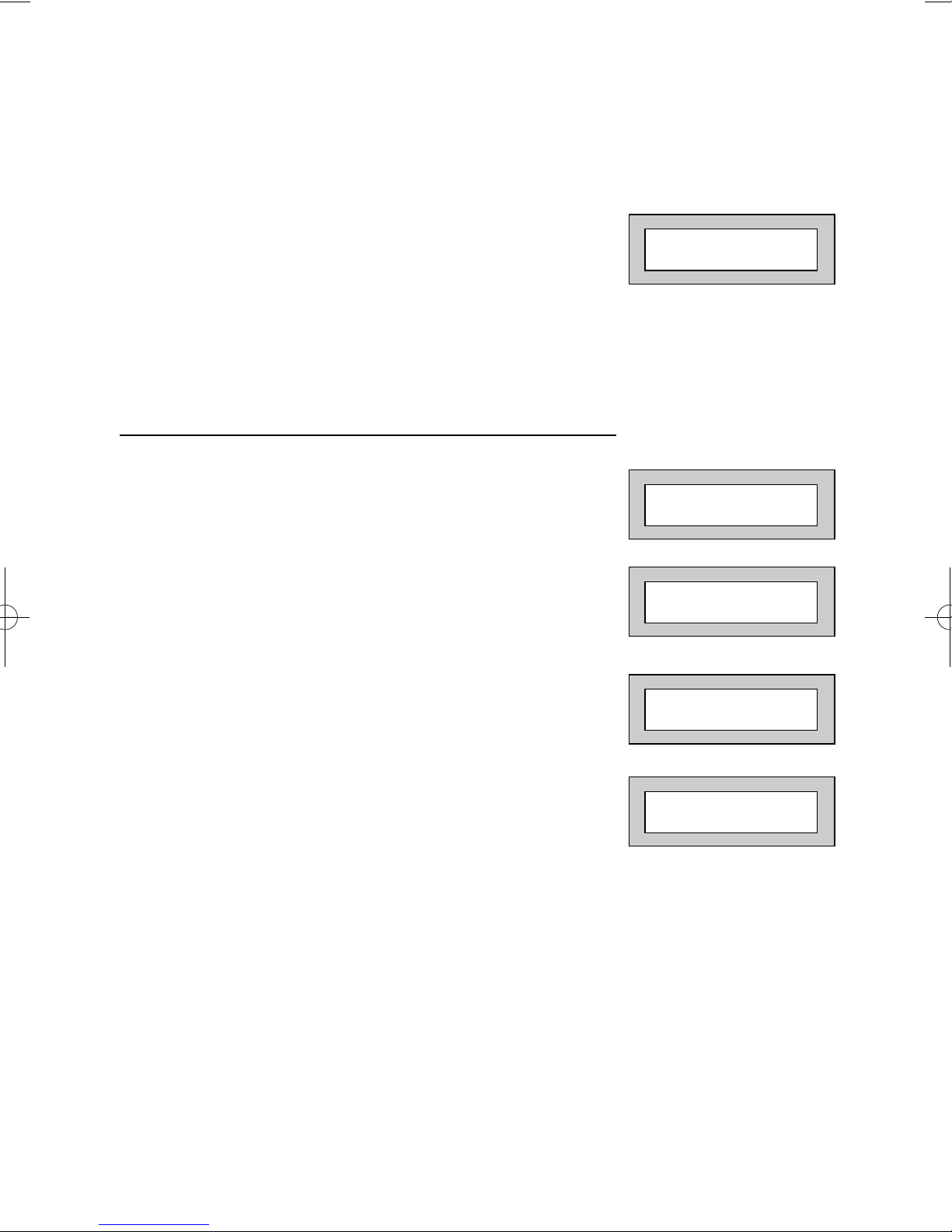
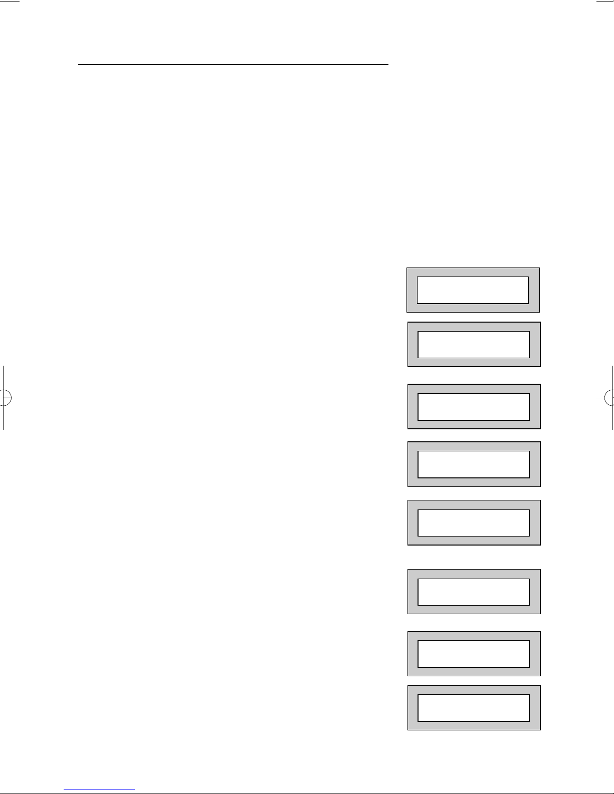
Testing The System (Master & Main codes only)
1) With the display showing:-
2) Enter a Master or Main level code,
the display will show:-
3) Press NO, the display will show:-
4) Press NO, the display will show:-
5) Press YES to test the system
6) The display will show:-
7) Then for example:-
8) Pressing 1 will enter zone Status mode (All zones will show on the display
and will be deleted as each zone is triggered). Press 0 to escape.
Pressing 6 will silence the internal sounder,
Pressing 4 will toggle the Strobe On/Off,
Pressing 9 will toggle the Bell On/Off.
01 JAN 18 : 58 : 01
Do you want to . .
SET the System ?
Do you want to . .
REMOVE Zones ?
Do you want to . .
TEST the System ?
1=Status 4 = Strobe
6 = Sounder 9 = Bell
< All Zones ok >
TESTING . . .
Page 10
GT490X
User Manual
9) Whilst in Test mode any zones violated
will sound the internal sounder (if it has
not been silenced) and show on the
display.
10) When you have finished testing the
system press 0 twice, the display will show:-
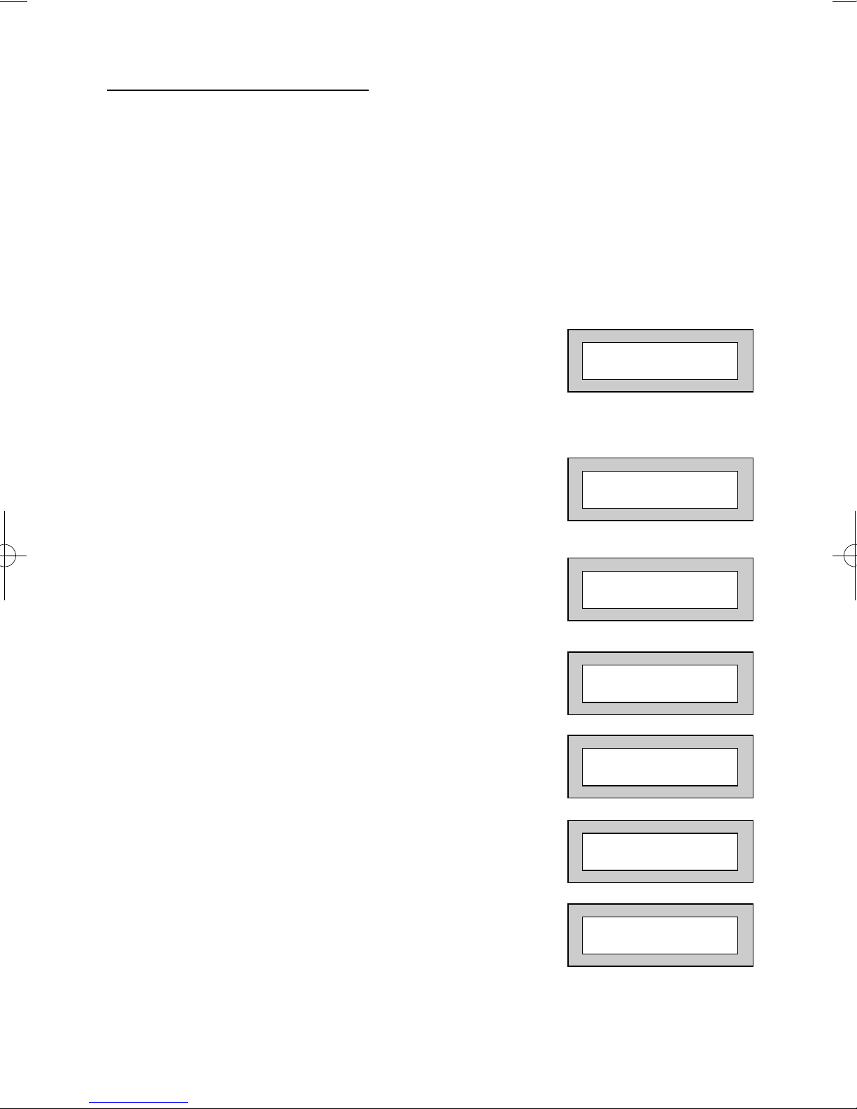
Viewing The Event Log (Master code only)
1) With the display showing:-
2) Enter a Master Code, the display
will show, for example:-
3) Press NO three times, the display
will show:-
4) Press YES, the display will show, for example:-
01 JAN 18 : 58 : 01
01 JAN 18 : 58 : 01
Do you want to . .
SET the System ?
Do you want to . .
View the LOG ?
Read Log
01 JAN 18 : 58 : 01

Page 11
GT490X
User Manual
5) This is the most recent event in the log.
Whilst viewing the Log,
Pressing NO will move back to the previous event.
Pressing YES will move forward to the next event.
Pressing 7 will take you to back to the last event of
the previous day.
Pressing 9 will take you forward to the first event of
the next day.
6) When you have finished viewing the Log press 0
twice. The display will show:-
Changing The Chime Status (Master code only)
The Chime zones will have previously been programmed by the installation company.
A Master level code may change the status of the Chime between On and Off. To do
so proceed as follows:-
1) With the display showing:-
2) Enter a Master Code, the display will
show, for example:-
3) Press NO four times, the display will show:-
01 JAN 18 : 58 : 01
01 JAN 18 : 58 : 01
Do you want to . .
SET the System ?
Do you want to . .
Change Chime ?

Page 12
GT490X
User Manual
4) Press YES the display will show, for example:-
Or:-
5) Press NO to change the status of the Chime,
then press YES, the display will show:-
6) Press 0 to escape, the display will show:-
Chime is Off ok ?
Chime is On ok ?
Do you want to . .
Change Chime ?
01 JAN 18 : 58 : 01
Page 13
GT490X
User Manual
Programming User Codes (Master code only)
The charts on pages 2 & 37 should be completed by the engineer/user for future
reference of what codes have been allocated on your system. Under no
circumstances should the actual user code be written down.
If your installation company has given you keyswitches for the operation of your
system some user codes may have been reserved for use by these keyswitches.
If your engineer has indicated (see pages 2 & 37) that some of the user
numbers on your system have been reserved you should not use them
whilst programming user codes. If you do so your system may be
adversely affected.
1) With the display showing:-
2) Enter a Master Code, the display will show:-
3) Press NO five times, the display will show:-
4) Press YES, the display will show:-
5) Enter the user number (1 to 15 that you
wish to program followed by YES, the
display will show:-
01 JAN 18 : 58 : 01
Do you want to . .
SET the System ?
Do you want to . .
Prog. USER CODES ?
Enter User No. - (1- 15) Then YES
Now Enter Code . .
- - - - - - Then YES

Page 14
GT490X
User Manual
6) Enter the code you require (codes may be 4,
5 or 6 digits) followed by YES.
(Entering 000000 will delete an existing code).
Note: If the code already exists, an error will be shown,
choose another code and return to step 6
7) The display will show:(not if user 1 is being programmed).
Press NO until the require level of code is shown
(Refer to page 3 for code level details. Refer to Advanced Code Programming
for details for User level of Control).
8) Press YES.
The display will show, for example:Code Groups are only used in conjunction with
controlling outputs. (See Advanced Code
Programming section for details).
9) Press YES. The display will show:This determines if using this user code to Set or
Unset the system will trigger the Vo-Comm.
(For more details on Vo-Comm please refer to the
Vo-Comm section). Press NO until the setting you
require is displayed (YES or NO).
Note:
The Vo-Comm will need to be programmed in
order for this option to work (please refer to the
Vo-Comm section in this manual).
10) Press YES. The display will show:If you wish to accept the name shown press
YES and jump to step 13.
Or
If you wish to change the name shown press
NO, the display will show:-
11) You may now enter up to nine characters for
the user name using the layout shown on the
following page for the allocation of characters.
User 02 Name
=User 02
Code Group
= None ok?
VoComm Trigger
= On Ok ?
User 2 Name
>-
Code Type . . = Master ok?
Page 15
GT490X
User Manual
12) Referring to the character map, enter the required
character (pressing the 3 key will display 'G', pressing
it again will show 'H' and again will show 'I '). Once
the correct character is displayed press YES and the
display will move on to the next position.
13) Continue entering characters (up to 9). If
you require a blank space, press YES while
the '-' is displayed.
14) As you press YES for the ninth character
(or if you have jumped from step 9) the
display will change to:-
15) If you wish to program other User Codes
return to step 4
Or
Press 0 to return to:-
Do you want to . .
Prog. USER CODES ?
01 JAN 18 : 58 : 01
123
4
56
78
9
0 YESNO
ABC
DEF
GHI
JKL
MNO
PQR
STU
VWX YZ
0-9
Your local installer: www.eaglesecuritysolutions.co.uk
Page 16
GT490X
User Manual
Programming Time & Date
1) With the display showing:-
2) Enter a Master Code, the display will show:-
3) Press NO six times, the display will show:-
4) Press YES the display will show:-
5) Press YES the display will show:-
6) Press YES to accept and the go to step 8
OR
Press NO display will show:Enter the Year then press YES.
7) Display will show:Press YES
8) Display will show:-
9) Enter the Day/Month (ie. 0706 for 7th June)
followed by YES. The display will show:-
10) Enter the time using 24Hr Clock (ie. 23:30 for
11:30pm) followed by YES the display will show:-
11) Press 0 the display will show:-
01 JAN 18 : 58 : 01
Do you want to . .
SET the System ?
Do you want to . .
Set DATE / TIME ?
Summer - Adjust is
On ok ?
Year is 2005
ok ?
Year is 2005
ok ?
Enter Year
20 - - Then YES
Enter Day / Month
-- -- / -- -- Then YES
Enter Hrs / Mins
-- -- : -- -- Then YES
Do you want to . .
Set DATE / TIME ?
07 Jun 23: 23: 02
Page 17
GT490X
User Manual
Vo-Comm (if fitted)
Vo-Comm is a method of transmitting signals to a standard land-line or mobile
telephone giving information regarding the status of your security system. This may be
in addition to, or instead of central station communications. It should be noted that VoComm should not under any circumstances be used to ring the Emergency Services
directly. It will not be possible to program 999, 911 or 112 as the telephone numbers
that the Vo-Comm will dial.
Before Vo-Comm can work several options will need to be programmed. Please read
below for information.
Vo-Comm Programming (if fitted)
1) With the display showing:-
2) Enter a valid Master Level
Code (5678 default).
Display will show:-
3) Press NO 7 times.
Display will show:-
4) Press YES.
Display will show:-
5) Press NO until display will shows:-
6) Press YES.
Display will show:-
Or for example
7) To enter or change this
number Press NO.
Display will show:-
01 Jan 00: 00: 01
Do you want to . .
Set the System ?
Do you want to . .
Set-Up VoComm ?
VoComm
= Off
VoComm
> On
VoComm Tel. No.1
Is Un-Programmed
VoComm Tel. No.1
12345678910
VoComm Tel. No.1
_ _ _ _ _ _ _ _ _ _ _ _ _
Page 18
GT490X
User Manual
8) Enter the telephone number
you require followed by YES.
9) Display will show:-
10) To enter or change the
number repeat from step 7
11) Display will show:-
12) To enter or change the
number, repeat from step 7.
13) Display will show:-
14) To enter or change the
number repeat from step 7.
15) Display will show:-
16) Press NO twice.
Display will show:-
17) Enter a unique Site ID for
the premises (00 to 99)
followed by YES.
This Site ID will identify what system is calling you.
18) Display will show:To change this press NO until the required
setting (On or Off) is displayed then press YES.
The term Open relates to the system being Unset.
With Open Reporting turned On the Vo-Comm will
report the system being opened (Unset) for all users
who have had the attribute of Vo-Comm Trigger
= On allocated in the User Code Programming.
VoComm Tel. No.2
is Un-Programmed
VoComm Tel. No.3
is Un-Programmed
VoComm Tel. No.4
is Un-Programmed
Site ID
= 00
Site ID
= _ _
Open Reporting
= On
Page 19
GT490X
User Manual
19) The display will show:-
The term Close relates to the system being Set.
With Close Reporting set to anything other then Off
the Vo-Comm will report the system being closed
(Set) for all users who have had the attribute of
Vo-Comm Trigger = On allocated in the User
Code Programming.
20) Options available are:
Off No system Close are reported
Full Set Only Full Sets are reported
Any Set All Sets (Full & Part) are reported
Press NO until your required setting is shown
then press YES. Display will show:-
21) Press NO (this is dealt with in the using Vo-Comm
section.
The display will show:-
22) Press 0 to return to:-
Close Reporting
= Off
Make an Alarm
Test Call ?
Do you want to . .
Set-Up VoComm ?
01 Jan 00: 00: 01

Page 20
GT490X
User Manual
Using Vo-Comm (if fitted)
Once Vo-Comm has been programmed (see previous pages)
the Vo-Comm will operate in one of two ways.
1) Alarms Only - The Vo-Comm will only communicate when an alarm occurs on
a Closed (Set) system. This mode is active when the Open / Close option
is Off.
2) Alarms & Status - The Vo-Comm will communicate when an alarm occurs or
when the system is Closed or Opened (Set or Unset).
Receiving a Call From Vo-Comm
When Vo-Comm calls you it will start to pass its message as soon as you pick up the
telephone.
At the end of the message you will hear a single tone, at this point press a numeric
key on your telephone keypad
twice
. A rising tone will be heard that indicates that the
call has been acknowledged.
If you do not acknowledge the call or hear the rising tone the Vo-Comm
will repeat the message several times and then go on to dial the
remaining telephone numbers until the call is acknowledged.
Messages From Vo-Comm
Two types of message will be sent by Vo-Comm. Either a status message or an alarm
message.
Typical Status Message
‘
Site 05 Close User 01
’
This would indicate Site ID 05 was Closed by User 1
The term Closed = Set
The term Open = Unset
Note:
In order for the Vo-Comm to report Openings and Closings, the Open
Reporting for that user must be programmed to On within the Programming
User Codes section.
Typical Alarm Message
‘
Site 05 Alarm Zone 06
’
This would indicate an alarm at Site ID 5 has occurred on Zone 6.
Page 21
GT490X
User Manual
User Initiating Remote Access (Optional)
Access Remote allows your installation company to examine your system and reprogram system settings as you need the changes without the need for an engineer to
visit your premises.
If your system has remote communications fitted your installation company may have
programmed the system so that you initialise the Access Remote call (usually on lines
with incoming calls barred).
To initiate the Remote Call follow the instructions below.
1) Negotiate with your installation company when you should
initiate the Remote Call.
2) With the display showing:-
3) Enter a Master Code, the display will show:-
4) Press NO seven times, the display will show:-
5) Press YES the display will show:-
until dialling commences
then:-
until connection
then:-
6) When your installation company has finished
the display will show:-
Note: In the event of any errors the display will show:-
(Check line is not in use or disconnected etc).
01 JAN 18 : 58 : 01
Do you want to . .
SET the System ?
Do you want to . .
Access Remote ?
Please WAIT
Please WAIT
Dialling
Please WAIT
Connect
01 JAN 18 : 58 : 01
! ! ! ! ERROR ! ! ! !
. . Try Again . .
Page 22
GT490X
User Manual
Resetting After an Alarm
Fault and Alarm Displays
Your installation company will have programmed the reset modes for your system so
that it complies to your insurance company and legislation requirements.
Your installation company will have informed you as to the type of reset that your
system is set for.
Before attempting to reset your system ensure that the system is Un-set.
1) In the event of a fault or an alarm occurring the
internal sounder will sound. (along with the external
bells for a full alarm) The display will show:(if the system is unset).
If the system is set, enter your code to unset it.
2) Press the NO key to view the cause of the Alarm or
Fault.
Note: If NO is NOT pressed then the alarm status will only be displayed for ten seconds
.
3) The display will then show:Enter your user code again.
4) The display will show:-
5) Press 0. The display will show:-
6) Press the NO key to view the cause of the alarm or
fault. The display will show, for example.
7) If more than 1 event is present the display will
show:The right arrow is now indicating that more events
are available for viewing.
! ! Enter Code ! !
! ! ! ! Check ! ! ! !
Do you want to . .
SET the System ?
! ! Enter Code ! !
! ! ! ! Check ! ! ! !
<<<< ALARM >>>>
Press NO to view
<<<< ALARM >>>>
Press NO to view
Zone 005 TAMPER
01 JAN 18 : 58 : 01
Zone 005 TAMPER
01 JAN 18 : 58 : 01 ->
Page 23
GT490X
User Manual
8) Press the YES key to view the next event and carry
on to view any others (if present). When viewing the
last event the display will show, for example.
The left arrow now indicates that you are at the end of events. The NO key
may be used to scroll back the opposite way.
Re-setting the system.
1) If the system is programmed for Any code reset
enter a User code. The display will show:-
Note: If NO is NOT pressed then the alarm status will only be
displayed for ten seconds
.
2) The display will then show:Enter your user code again.
3) The display will show:Press the Reset key
Or
4) Press YES. The exit tone will sound and the display
will show, for example:-
5) Enter the code again to abort the setting.
6) The system is now reset
Or
If a higher level of code is required one of
the following displays will be shown:-
Use a Master code to reset the system.
Or:-
Call the installation company
Or:-
Call the central station or installation company
(as instructed) and quote the number given
Or:-
Can't Set Use
Master Code
Can't Set Use
ENGNR Code
Can't Set Use
ENG +Anti Code 1234
Can't Set Use
Anti Code 1234
EXIT!
All Zones ON 15
Time will count down
<<<< ALARM >>>>
Press NO to view
! ! Enter Code ! !
! ! ! ! Check ! ! ! !
Do you want to . .
SET the System ?
Zone 005 TAMPER
01 JAN 18 : 58 : 01 <-

Page 24
GT490X
User Manual
7) To reset the system with an Anti-Code, contact
the central station or engineer (as instructed by
the installation company) and quote the number
given by the display.
8) The central station or engineer will give a return
Anti-Code, ( this may contain the YES & NO keys)
for example 5, YES, 2, 4.
9) Enter this Anti-Code into the keypad.
10) The system is now reset.
Page 25
GT490X
User Manual
Setting Engineer Authorisation
A User Code may be required to authorise an engineer to gain access to the system in
the event of service or maintenance schedules. The level of User Code required to
authorise the engineer to access the system is set within the User Menu that is
accessed via a Master Level Code.
Setting the Engineer Authorisation Level
1) Enter a Master User Code. The display will
show:-
2) Press NO until the display shows:Then press YES.
3) Press NO until the required setting is displayed:-
Master, Main and Any are user code levels.
If None
is selected, no user authorisation will be required to grant engineer access to
the alarm system. However, the panel will generate an audible sound for
approximately 8 seconds to indicate that the engineer is on site.
4) Press YES. The display will show:-
(This option is dealt with later).
5) Press YES. The display will show:-
6) Press 0 to return to:-
Using Engineer Authorisation
A valid Authorisor code will be required to give an engineer access to the alarm
system. This may be done in two ways.
1) The engineer will enter his/her code. The display
will show:-
2) Enter a valid level of User code to grant the
engineer access.
Do you want to . .
SET the System ?
Do you want to . .
Authorise Engnr ?
Engnr Authorisor
=Any
Engineer Access
is Off Ok ?
Do you want to . .
Authorise Engnr ?
01 JAN 18 : 58 : 01
Enter Authorisor
Code . . . . . .

Page 26
GT490X
User Manual
Or
1) Enter a Master User code. The display will show:-
2) Press NO until the display shows:-
3) Press YES. The display will show, for example:-
4) Press YES. The display will show:-
5) Press NO. The display will show:-
6) Press YES. The display will show:-
7) Press 0 to return to:-
Provided that the next code entered is a valid engineer code, access will be granted to
him/her without further user intervention.
Do you want to . .
SET the System ?
Do you want to . .
Authorise Engnr ?
Engnr Authorisor
=Any
Engineer Access
is Off Ok?
Engineer Access
is On Ok?
Do you want to . .
Authorise Engnr ?
01 JAN 18 : 58 : 01

Page 27
GT490X
User Manual
G-Tag Introduction
G-Tag is a method of Setting and Unsetting your security system via a Proximity
Reader and a Tag. The Proximity Reader may be an internal reader that is fitted on to
the inside of a doorframe etc or an external reader that is fitted into the doorframe on
the outside of the premises.
Legislation contained within BS8243 does not allow for the
transmission of confirmed alarm signals once the entry time has
started if the user of the security system is using a manual code
entered into the keypad. G-Tag conforms fully with the
requirements of this legislation relating to confirmed alarms on
entry.
Because the G-Tag uses Proximity Technology there are no batteries to change in the
unit, it is small enough to be carried on the users key ring and one Tag may be used
on multiple security systems and some door entry systems.
Programming G-Tag Tags Onto Your System
Programming The Tags onto your system is very simple. Follow the instructions for
programming User Codes onto your system up to the point when you would enter the
User Code. At this point present you Tag to the Proximity Reader and a code will be
entered for you. Continue with the instructions entering the User Name etc. Each GTag will be identified on an individual basis when it is used to Set or Unset the system.
4 Wire Keypad
Each G-Tag need only to be programmed onto one of the 4 wire keypads in multiple
reader installations.
Using G-Tag On Your System
G-Tag is a method of entering a code into your security system.
To Set Your System Using G-Tag
When you wish to Set your system simply present your Tag to the Proximity Reader
and exit the protected area following the normal Setting You System Instructions.
To Part 1 Set Your System Using G-Tag
If using G-Tag Part 2 and Part 3 Setting will not be available (a manual code should be
used to Part 2 or 3 Set the system).
To Part 1 Set your security system press YES twice
the display will show:-
Present your Tag to the Proximity Reader and exit the
protected area following the normal Part Setting You System Instructions.
G-Tag Fob
Press . .
CODE to Part - Set

Page 28
GT490X
User Manual
Display Status Blanking
It may be a requirement that the Status (Set or Unset display) of the security system is
not displayed. If this option has been invoked by your installation company the Set or
Unset Status will only be displayed for ten seconds when the system is Set or Unset.
The top line of the display will then be blanked off.
You may check the Status of the system at any time by pressing the YES key and then
entering a valid User Code.
If the system was Set when you did this the display will ask if you wish Unset the
system. To do so press YES within ten seconds.
If the system was Unset when you did this the display will ask if you wish Set the
system. To do so press YES within ten seconds.
If you do not choose to Set or Unset the system within the ten seconds the top line of
the display will be blanked out and the code entry will be invalidated.
Keypad Alert
If programmed by your installation company, the two PA keys (or keys 1 & 3, if
programmed by the engineer), when pressed together will act as alert keys. The exact
function will depend on what they have been programmed for. But for example, if they
are programmed as panic, pressing them will activate the alarm when the system is set
or unset.
Keypad Tamper
The keypad will monitor the number of attempts without a valid User Code being
entered. More than seven attempts will cause a keypad tamper and lock-out the
keypad for 90 seconds. This will be displayed as ‘LOCK-OUT Check’ and will require a
valid User Code entry to stop the sounders (only after 90 seconds). If the system was
Unset only the internal sounders will operate. If the system was Set a full alarm will be
generated.
System Tampers
The full security system is tampered, any attempt to remove covers from Keypads,
Control Panel, Keypads, Bell Box(es) or detectors will cause a tamper alarm. This also
applies to cut cables. If the system is Unset when the Tamper occurs the alarm will be
internal sounders only. If the system is Set a full alarm will be generated.
The alarm may be silenced by entering a valid User Code. The system may only be
Reset when the Tamper has been cleared, otherwise another Tamper alarm will be
generated.

Page 29
GT490X
User Manual
Mains Failure
In the event of a Mains Power Failure the display will show:-
At this point the system will revert to battery back-up. The battery will only have a
limited time that it can sustain the system for.
Note: Your installation company will have determined what size battery is
required to comply with legislation. It is important that your security
system is serviced on a regular basis on order that it continues to
comply with the legislation. Servicing may also be a requirement of
you insurance policy.
In the event of a sustained power cut the system battery will
continue to supply the system until the battery voltage falls
to a set point, at this stage the display will show:-
A fault sounder will start, enter a valid User Code to stop the fault sounder.
At this point it is essential that you contact your installation company.
Setting the system with Mains Fail
In the event of a short term power cut, where it is known when power will be restored,
(e.g. Engineers working on power lines that affect your premises) it might be necessary
to set this system. Please follow the steps outlined below:
1) With the display showing:-
Note: In the event of a mains power failure, the control panel will display
that a fault has occurred if the pre-programmed time has been
exceeded.
2) Enter your User code. The display will show:-
3) Enter your User code again.The display will then
show:(Followed by YES if a Master or Main type code
has been used).
4) Then press YES. The display will show:-
Note: The display will switch between the EXIT display and
the Power Cut FAULT display as the time counts down.
! ! Enter Code ! !
! ! ! ! Check ! ! ! !
Fuse / Bat. FAULT
! ! ! ! Check ! ! ! !
! ! Enter Code ! !
! ! ! ! Check ! ! ! !
Power Cut FAULT
01 JAN 18 : 58 : 01
Power Cut FAULT
Can’t Set ! Check
EXIT!
All Zones ON 15
Time will count down
Page 30
GT490X
User Manual
5) Exit the premises via the authorised exit route.
6) Once the premises are secure listen (from outside
the protected area) and wait until the exit tone finishes before leaving.
Re-setting the display after a Mains Fail
Note: In the event of a Mains Power Failure, the control panel will display that a fault has occurred if the
pre-programmed time has been exceeded.
1) In the event of a mains power failure the display
will show:-
2) Enter your User code. The display will show:-
The right arrow is now indicating that more events are available for viewing.
Press the YES key to view the next event and carry on to view any others.
When viewing the last event the display will show,
for example.
The left arrow now indicates that you are at the end of events.The NO key
may be used to scroll back the opposite way.
3) Enter your User code again.The display will then
show:(Followed by YES if a Master or Main type code
has been used).
4) Enter the code again to abort the setting or press
the Reset key. The display will show:-
The system is now reset.
! ! Enter Code ! !
! ! ! ! Check ! ! ! !
Power Cut FAULT
01 JAN 18 : 58 : 01->
Mains Ok Ack
01 JAN 18 : 58 : 01<-
EXIT!
All Zones ON 15
Time will count down
01 JAN 18 : 58 : 01

Page 31
GT490X
User Manual
Advanced Code Programming
This section cover the programming and use of Advanced Codes. The Code Level of
Control is classed as an Advanced Code. Several parameters will need to be
programmed by the installation company before a Control Code may be programmed
into the system. You should also note that a Code Level of Control may never Set the
system.
Typically a Control Code would be used for turning on an output or act as a limited
door access system. In order for this to function additional hardware would be
required.
To program a Control Code level.
Follow the normal instructions for programming codes.
At the Point when you are asked for the Level choose Control.
When asked for the Code Group enter 1 to 8 (your installation company will have given
you what group to use).
Then choose Can or Cant Unset (dependant on your requirements).
Follow the normal instructions to the end for programming codes.
Using Advanced Codes
Two typical uses for Advanced Codes are.
1) To turn on an output (e.g a light).
Enter the User Code or present your Tag the output will turn On.
Enter the User Code or present your Tag again the output will turn Off.
2) To open a door (e.g door access with limited function).
Enter the User Code or present Tag to external Tag reader door will release.
for the time period determined by your installation company.

End User Training
It is the responsibility of your Installation Company to provide adequate training for
people who will be expected to use the system. If further training is required for new
staff etc please contact your Installation Company. This user Manual should be
accessible by all people who will be using the system. If extra copies are required the
manual may be downloaded from our web-site www.riscogroup.co.uk
Testing /Servicing Your System
The system you have installed will give many years of service but it should be tested
and serviced on a regular basis by a qualified installation engineer. It may be a
condition of your insurance policy and/or your Police response that it is serviced at
regular intervals. For details on service periods for your system please contact your
installation company.
Page 32
GT490X
User Manual

Page 33
GT490X
User Manual
Notes

Page 34
GT490X
User Manual
Notes
Page 35
GT490X
User Manual
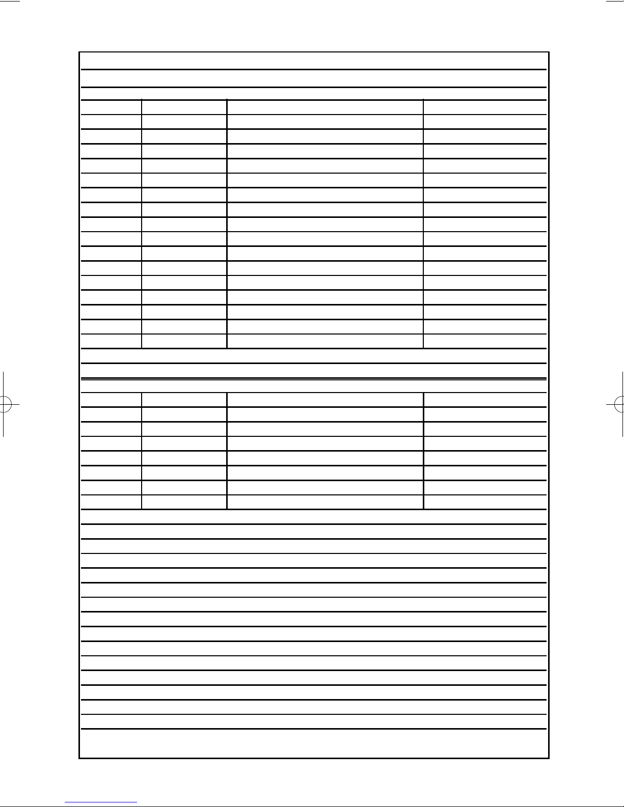
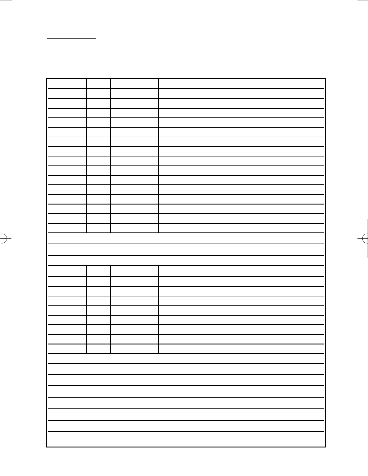
System Attributes
Control Panel Zones
Zone No. Zone Type Descriptors Part Info
Example E/E Front Door 1&2
1
2
3
4
5
6
7
8
9
10
11
12
13
14
15
16
Radio Zones (If Fitted)
Zone No. Zone Type Descriptors Part Info
91
92
93
94
95
96
97
98
Zone Notes
Page 36
GT490X
User Manual
Service Record
Date Comments Signature
Alarm Reset Type:- Tamper Reset Type:-
Service Company:-
Tel:- Fax:-
Service Notes
Page 37
User Manual
GT490X
User Chart
Please use this chart to indicate what user names have been programmed onto your
system and those that are in use.
In Use Code/G-Tag User Name
User 1
User 2
User 3
User 4
User 5
User 6
User 7
User 8
User 9
User 10
User 11
User 12
User 13
User 14
User 15
Note: Under no circumstances should you write down the actual code
Radio Fob Users (If Used)
In Use User Name
User 81
User 82
User 83
User 84
User 85
User 86
User 87
User 88
Use this space to record any codes that have been reserved for Keyswitch(es)

Risco Group UK Ltd
Commerce House, Whitbrook Way
Stakehill Distribution Park,
Middleton. Manchester. M24 2SS
United Kingdom
Internet: www.riscogroup.com
e-mail: sales@riscogroup.co.uk
Risco Group UK Ltd reserve the right to amend the software and features without prior notice.
PR5847 Rev1.1 5IN490UM B
Your local installer: www.eaglesecuritysolutions.co.uk
 Loading...