

Risco GardTec 350+ Installation Instructions Manual

Installation
Instructions
GG
GG
aa
aarrrr
dd
dd
TT
TT
ee
ee
cc
cc
33
33
55
55
00
00
++
++
CC
CC
oo
oo
nn
nnttttrrrr
oo
oollll
PP
PP
aa
aa
nn
nn
ee
eellll
GARDTEC
350
Engineers Manual
IMPOR
IMPORTT
ANT!
ANT!
Input: AC230V +/-10% ~50Hz 125mA Max. 35W Max
Nominal Temp Range: 0 - 50°C
Plastic For Indoor Use Only
This equipment is intended only for use as a Security Alarm Control Panel. Adequate
ventilation away from heat and humidity must be provided. The unit must be fixed
securely to a non-flammable surface using suitable fixings.
All mains wiring must be to BS7671 (1992) IEEE wiring regulations (or appropriate
international regulatory standards). See Mains Supply Connection section within this
manual for more detailed instructions.
All wiring must be protected from sharp or jagged edges.
All Low voltage (alarm) wiring must be to the appropriate international regulatory
standards and comply to good wiring practice.
Replacement fuses should be of the same type and rating conforming to IEC 127.
The maximum current draw from the unit for all output combinations must not
exceed 1Amp (350+ only). 800mA 350 Control Panel.
The unit is intended for use with a suitable re-chargeable lead acid battery
permanently connected to the appropriate terminals.
All documentation and manuals must be thoroughly read by suitably qualified
installation personnel prior to installation.
The unit has no user serviceable parts inside. Internal access should only be by suitably qualified personnel.
Mains Earth
Provision is provided for an earth connection within the mains input connector block,
this connection is for protection of the wiring only and is not functional for the unit.
Battery Fuse
An in-line Battery Fuse has now been incorporated into this product. The fuse rating
is 2 Amp Anti-Surge. The fuse holder is spring loaded, therefore you should ensure
that the battery lead is not under tension in order to maintain a good connection
between the fuse and the holder.To change the fuse, push the two halves of the
holder together and twist anti-clockwise. Please ensure correct battery charge on
completion of the installation and during each service visit.

Contents
Introduction 1
Keypad Description (& changing orientation) 1
LED Functions 1
Programming Modes 2
Engineer Programming 4 - 9
Programming General Routine 4
Programming Bell Option 5
Programming Entry Option 6
Programming Exit Option 7
Programming Sounder Option 8
Programming Zone Option 9
Engineer / User Programming 10 - 13
Overview 10
Removing Zones 10
Testing the System 10
Reading the Log 11
Setting Chime On/Off 11
Programming Engineer Code 11
Full Setting the System 12
Part Setting the System 12
Unsetting the System 13
Resetting After an Alarm 13
Factory Defaults (& Options) 13 - 14
Control Panel Fixing 15
P.C.B Layout 16
Output Connections 17
Input Connections 18
Mains Connections 19
Detector Wiring 20
Tamper Wiring 21
Speaker Wiring 22
Self Actuating Sounder Wiring 23
Conventional Bell Box Wiring 24
Fault Finder 25 -26
Zone Terminology 27
User Code Types 27
Gardtec
350
Specification 28
System Record 29
GARDTEC
350
Patent Pending
GARDTEC
350
Engineers Manual

INTRODUCTION
The Gardtec 350 is a five zone microprocessor based Control panel. Each of these
zones is fully programmable.
The unit may be mounted either vertically or horizontally to enhance it’s flexibility.
Three part set suites are available, zones programmed as part set zones will be
removed when the appropriate part set is selected. The power supply rating of the
Gardtec 350 is 1Amp, enough to cope with the average domestic or small commercial
installations. The compact size coupled with the range and variety of functions make it
an ideal choice for the domestic/ small commercial, bells only system. Factory codes
are 1234 for engineer and 5678 for user.
KEYPAD DESCRIPTION
The keypad takes the form of a 4 x 3 (0-9 YES NO) matrix. The orientation of the key
numbers will depend on the Gardtec 350 being mounted vertically or horizontally. The
unit is supplied with the horizontal label fitted and the vertical label is available separately. If you wish to change the orientation of the panel fit the vertical keypad
overlay. A delay will occur when the panel is powered up. Press 00 for the keypad you have chosen during this power up delay. The orientation of the keys is
now correct for your chosen keypad.
Pressing 4, 6, YES, NO during the power up delay will revert the unit back to factory defaults. NOTE: this will not affect the keypad orientation.
LED FUNCTIONS
The display is via eight LEDs. There are three modes of LED operation, two user and
one engineer mode. The two user modes for the LEDs are shown on the keypad overlays. During primary (setting, unsetting etc) operation the functions shown in Black are
used. During secondary (user programming) mode the functions shown in White are
used.
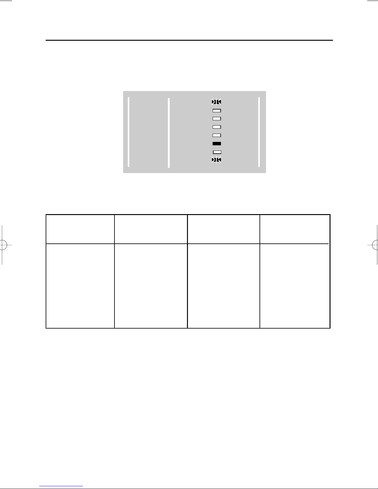
When engineer programming mode is being used please use the keypad overlay
shown below:-
Page 1
GARDTEC
350
Engineers Manual
300 Series
POWER
DAY
Z1
Z2
Z3
Z4
Z5
TAMPER
BELL
ENTRY
EXIT
SOUNDER
ZONE
ENTER
Use this display
layout when in
engineer programming mode

Throughout this manual reference to the display will be accompanied by a diagram
showing the status of the LEDs. Three modes are possible from each LED and will be
shown as follow:-
PROGRAMMING MODES
Two programming modes are available to the engineer: Engineer programming and
Engineer/ User programming.
To enter Engineer Programming Mode with the panel unset enter engineer code and
press YES. The following options may then be programmed:-
BELL OPTION (BELL TIME and number of RE-ARMS)
ENTRY OPTION (ENTRY TIME 1 and ENTRY TIME 2)
EXIT OPTION (FULL SET EXIT TIME and PART SET EXIT TIME)
SOUNDER OPTION (ENTRY/EXIT LEVEL, CHIME LEVEL, SILENT PART SET and
PROGRAMMABLE OUTPUT MODE).
ZONE OPTION (ZONE NUMBER, ZONE TYPE, PART SET STATUS and CHIME
STATUS)
To enter Engineer/User Programming Mode with the panel unset enter the engineer
code and press YES. The following options may then be programmed:-
REMOVE OPTION (Allows individual Zones to be Removed)
TEST OPTION (Allows the System to be Tested)
LOG OPTION (Allows the Log to be Read)
CHIME OPTION (Allows the Chime option to be turned On and Off globally)
PROGRAM (ENGINEER CODE) OPTION (Change Engineer Code)
The same options in Engineer/User Programming Mode are available in the User
programming Mode with the amendment that USER CODES are programmed.
Page 2
GARDTEC
350
Engineers Manual
= OFF
= ON
= FLASHING

The options available from the two engineer modes are illustrated below.
Enter engineer code
System starts to set
Select Part set options or
System sets
Page 3
GARDTEC
350
Engineers Manual
Use REMOVE option
(Page 10 )
Use TEST option
(Page 10 )
Use LOG option
(Page 11 )
Use CHIME option
(Page 11 )
Use PROGRAM option
(Program ENGINEER CODE)
(Page 11 )
Program BELL options
(Page 5 )
Program ENTRY TIME options
(Page 6 )
Program EXIT TIME options
(Page 7 )
Program SOUNDER options
(Page 8 )
Program ZONE options
(Page 9 )
Press
NO
Press
YES
Press
NO
Press
NO
Press
NO
Press
NO
Press
NO
Press
NO
Press
NO
Press
NO

ENGINEER PROGRAMMING
Engineer programming general routine:
The general programming routine is as follows:-
Enter the Engineer Code. 1234 factory default (Panel will start to set).
Press YES (Before entry time expires) the POWER AND Z1 LEDs will now flash. This
is Engineer mode. From this point on the display layout on page 1 (or the engineer programming card) is used.
Press NO until the LED for the option you wish to program is flashing.
Press YES (the LED for that option will now illuminate steadily and the Enter LED will
flash).
Enter an appropriate four digit number.
Press YES. (An audible tone will be heard if option is updated).
Use the NO key to move onto other option(s) or the 0 key to quit Engineer
Programming mode.
A more detailed method for each option now follows
SYSTEM PROGRAMMING
With the control panel unset Enter the Engineer Code. 1234 factory default (Panel will
start to set).
Press YES before entry time expires. (Exit sounder will silence). The display layout
shown on page 1 (or the engineer programming card) is used whilst in this mode.
The POWER LED will be flashing. (This shows you are in engineer mode).
The BELL LED will also be flashing. (This is asking do you want to program this function).
If at any time during the Exit time the code is re-entered the panel will return to
DAY (Unset) mode.
Page 4
GARDTEC
350
Engineers Manual
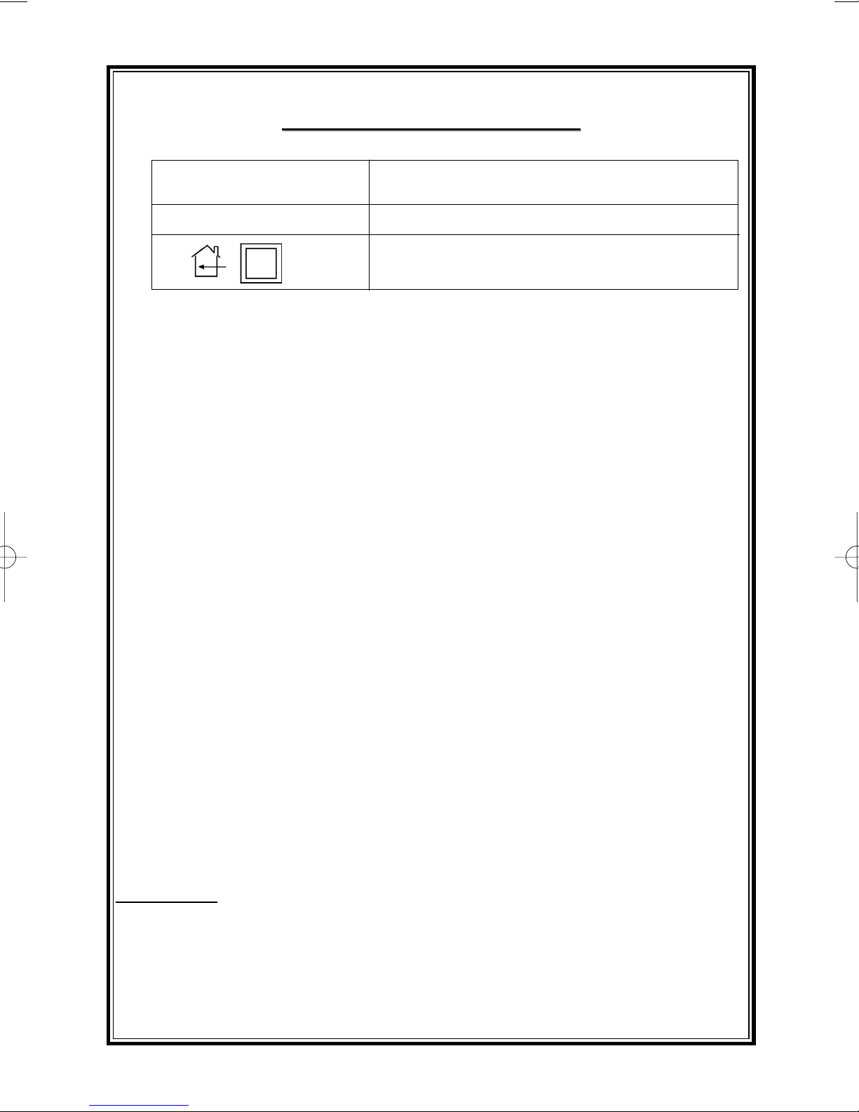
SYSTEM PROGRAMMING (BELL OPTION)
With the Control Panel in engineer mode PRESS NO until the POWER & BELL LEDs
are FLASHING.
PRESS YES display will show:-
The Enter LED is now flashing asking you to enter a four digit number.
Choose from:-
As an example 2003 would be Bells on for 20 Minutes with 3 Re-Arms
Enter your four digits followed by YES. (A tone will be heard if option is updated).
To move onto another option use the NO key.
If you wish to escape out of engineer mode and return to Unset, PRESS 0.
Page 5
GARDTEC
350
Engineers Manual
300 Series
POWER
DAY
Z1
Z2
Z3
Z4
Z5
TAMPER
BELL
ENTRY
EXIT
SOUNDER
ZONE
ENTER
1st & 2nd Digits
Bell On Time
(Minutes)
3rd & 4th Digits
Number of Re-Arms
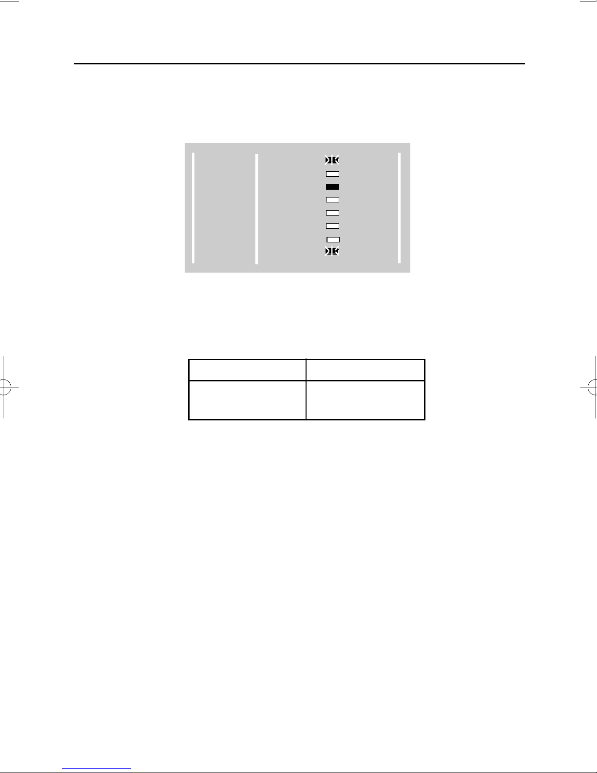
SYSTEM PROGRAMMING (ENTRY TIME OPTION)
With the Control Panel in engineer mode PRESS NO until the POWER & ENTRY
LEDs are FLASHING.
PRESS YES the display will show:-
The Enter LED is now flashing asking you to enter a four digit number.
Choose from:-
As an example 2010 would be 20 seconds Entry Time 1 and 10 seconds Entry Time 2
Enter your four digits followed by YES.(A tone will be heard if option is updated).
To move onto another option use the NO key.
If you wish to escape out of engineer mode and return to Unset, PRESS 0.
Page 6
GARDTEC
350
Engineers Manual
300 Series
POWER
DAY
Z1
Z2
Z3
Z4
Z5
TAMPER
BELL
ENTRY
EXIT
SOUNDER
ZONE
ENTER
1st & 2nd Digits
Entry Time 1
(Seconds)
3rd & 4th Digits
Entry Time 2
(Seconds)
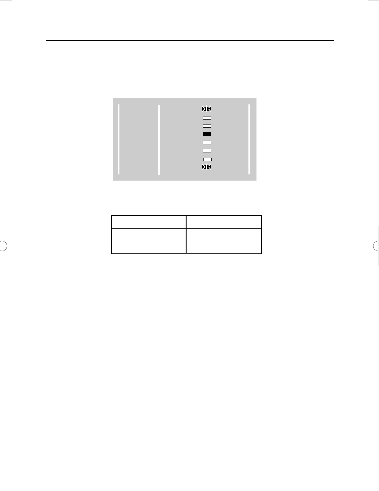
SYSTEM PROGRAMMING (EXIT TIME OPTION)
With the Control Panel in engineer mode PRESS NO until the POWER & EXIT LEDs
are FLASHING.
Press YES display will show:-
The Enter LED is now flashing asking you to enter a four digit number.
Choose from:-
As an example 2010 would be 20 seconds Full Set Exit Time & 10 seconds Part Set
Exit Time.
Enter your four digits followed by YES.(A tone will be heard if option is updated).
To move to another option use the NO key.
If you wish to escape out of engineer mode and return to Unset, PRESS 0.
Page 7
GARDTEC
350
Engineers Manual
300 Series
POWER
DAY
Z1
Z2
Z3
Z4
Z5
TAMPER
BELL
ENTRY
EXIT
SOUNDER
ZONE
ENTER
1st & 2nd Digits
Full Set Exit Time
(Seconds)
3rd & 4th Digits
Part Set Exit Time
(Seconds)
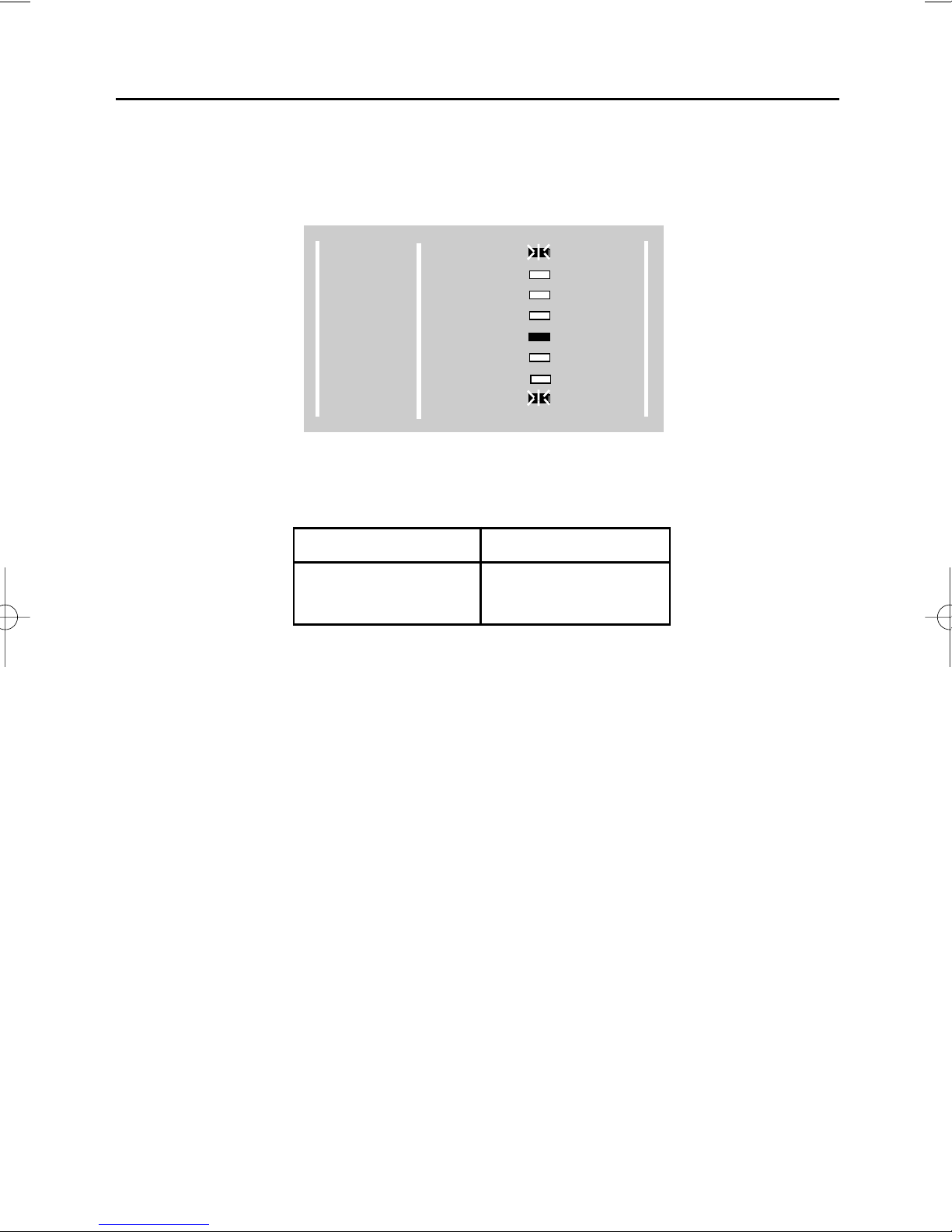
SYSTEM PROGRAMMING (SOUNDER OPTION)
With the Control Panel in engineer mode PRESS NO until the POWER & SOUNDER
LEDs are FLASHING.
PRESS YES display will show:-
The Enter LED is now flashing asking you to enter a four digit number.
Choose from:-
Note: The Chime and E/E volume adjustment is extended through the use of the
onboard potentiometer on the Gardtec
350+.
As an example 5501 would give a volume level of 5 for both Entry/Exit and Chime volume, all part sets silent and the programmable terminal will pulse Off during the setting
period.
Enter your four digits followed by YES. (A tone will be heard if option is updated).
To move to another option use the NO key.
If you wish to escape out of engineer mode and return to Unset, PRESS 0.
Page 8
GARDTEC
350
Engineers Manual
300 Series
POWER
DAY
Z1
Z2
Z3
Z4
Z5
TAMPER
BELL
ENTRY
EXIT
SOUNDER
ZONE
ENTER
1st Digit
Chime Volume
0 - 9
2nd Digit
Entry/Exit Volume
0 - 9
3rd Digit
Setting Sounders
0=All Parts silent
1=Part 2 silent
2=Parts 1&3 silent
3=All parts audible
4th Digit
Programmable
Terminal
0 = Pulse On
1 = Sw+ when set
2 = Pulse Off
3 = On with Bell
4 = On with Strobe
5 = On in En/Ex
6 = On in Test
7 = On in Int/Alarm
 Loading...