

Risco eyeWAVE Installation Instructions Manual
eyeWAVE™ Wireless
PIR Camera
Models: RWX95CM/RWX95CMP
EN
FR IT ES SE
Installation Instructions
Description
The eyeWAVE™ Wireless PIR Camera Detector
(RWX95CM) / Wireless PIR Pet Camera Detector
(RWX95CMP) is a battery powered PIR detector that
includes an integrated camera for visual verification and
is compatible with RISCO security systems.
Features include:
•
RWX95CMP PIR coverage 12m (40’) wide
angle, RWX95CM PIR coverage 15m (50’ )
wide angle
•
VGA or QVGA camera resolution with ~90° field-ofview
•
Discreet IR flash allows imaging in complete
darkness, up to 10m (33’)
•
Sequence of images upon event, configurable
number and fps
•
During disarm, events are ignored to save battery
and for privacy
•
On-demand images initiated from authorized
Smartphone or web browser
•
Images stored on detector until transmission to
panel complete
•
Back tamper for higher security in surface or corner
installation
•
Includes 2 long-life 3V lithium ba tteries
Installation
Step1: Preliminary Considerations
Select the mounting location for best coverage of the
area that is to be protected (see Coverage Patterns and
Preliminary Considerations).
Step 2: Registering the Detector into the
System
The eyeWAVE must identify itself to the system receiver
in a device allocation (enrollment) process, which can be
performed by either RF sequence registering or entering
the detector’s 11-digit serial number into the system or
using RF mode panel quick key programming
Sequence:
From the panel: 2) Radio Devices > 1) Allocation > 1) By
RF or 2) By Code.
Through the Configuration Software: Click Radio
Device Allocation > Enter Serial Code: [045] + [8 digits];
Indexed: Automatic or manually designated 1-32;
Accessory Type: 2-Way Detector (displayed)). Then
click Allocate: RF Allocation is performed.
For more information refer to the System Installer Manual.
Step 3: Mounting the Detector
1. Open the knockout holes of the mounting
bracket, and use them as a template for mounting
(see Figure 3).
For Pet friendly model:
In order to optimize pet immunity the following guide
lines are recommended:
Mount the detector vertically at right angles to the floor.
Make sure an animal cannot get above height of 1.5m
(5') by climbing on furniture, shelving or stairs.
2. Fasten the cover to the base of the detector by
inserting and fastening screw into the hole located
inside the battery compartment (see Figure 2)
3. Insert the batteries and close the battery
compartment cover (see Figure 2)
4. Once the bracket is installed, slide and lock the
detector onto the mounting bracket in reverse
sequence (see Figure 4)
5. Perform a Walk Test as described in the Walk Test
section (see Figure 5).
6. Insert and fasten screw (C) into the hole located at
the bottom of the detector to lock the detector to the
mounting bracket (see Figure 4).
Step 4: Performing a Walk Test
Upon inserting the batteries, the detector goes into a
Walk Test mode for 20 minutes and then automatically
returns to Normal mode (to save battery power). During
Walk Test Mode, the detector transmits a signal, after
each detection. Walk test the entire field of view of the
detector and observe the LED for confirmation. Verify
that the receiver is properly receiving the signals.
To manually initia te a walk test from the control panel:
Installation Menu: 2) Testing > 2) Zone > 3) Walk Test 1)
Start Walk Test. The detector remains in walk test mode
until any key on the panel is pressed. Display test
results as follows: Installation Menu: 2) Testing > 2)
Zone > 3) Walk Test 2) Walk Test Results
Camera Configuration
Being bi-directional, the detectors parameters can be
modified from the keypad or from the system
configuration software according to your needs
PIR
Sensitivity:
High/Low (Default: Low)
Supervision
Time:
0-255 minutes (Default: 15 min)
LED:
On/Off (Default: On)
Operation
Mode:
Walk Test: The detector will transmit
after each detection
Normal (Default)
Configure the camera settings through the RISCO
Configuration Software (right-click on the Serial Code
field in the Zones node screen and in the displayed popup click Additional..) or through the panel quick key
programming sequence as follows (default in bold):
Programming > 2) Radio Devices > 2) Modification > 1)
Zone [Select (1–32)] > 1) Parameters > 6) Advanced 5)
Camera Parameters:
Images at Alarm:
3 (1 to 7 images)
Image Interval:
0.5 sec (0.5, 1, 2 seconds)
Pre-Alarm Image:
Yes (Yes, No) (Image capture upon
each arm)
Image Resolution:
QVGA (QVGA 320X240, VGA
640X480)
Image Quality:
High (High, Low)
Colour Image:
Colour (Colour, B&W)
Image upon request
Snapshot images can be taken using web/smartphone
apps (on panels supporting these applications).
Event Reporting
Every event detected by the PIR camera is recorded into
the camera’s memory. The event record consists of the
date and time mark, detail description of the event
including its source and a video record.
LED Status
On:
Alarm
Blinking three times (in alarm
mode):
Low battery
Blinking four times (in initial
learning mode)
Successful write
operation
Diagnostics
You can perform diagnostic tests on your detector using
the keypad or the configuration software. Diagnostics
includes testing the detector battery status and the
communication between the detector and the panel. For
additional information refer to the System Installer Manual.
To replace the batteries:
1. Remove the detector from the mounting bracket (see
Figure 1).
2. Open the battery cover (see Figure 2).
3. Replace the batteries. Pay attention to the right polarity.
4. Close the battery cover.
CAUTION – Risk of explosion if battery is replaced by
an incorrect type. Dispose of used batteries according to
local regulations.
NOTE – After replacing the batteries and closing the
tamper, the detector will automatically go into in Walk
Test mode for 20 minutes.
Specifications
Electrical
Battery Type:
2 x CR 123, 3V Lithium Battery,
1450mAh
Battery Life:
2 batteries – 3 year typical lifetime
Low battery
threshold
2.6V
Current
Consumption:
60 μA standby;
200 mA max. peak at capture with flash
Power Output
Security 868.65Mhz:10mW
Camera 869.525Mhz: 500mW
Supervision
Transmission:
0-255 minutes
RF transmitting
frequencies:
868.65 MHz; 869.525 MHz for model
RWX95CM8
433.92 MHz; 916 MHz for model
RWX95CM4
Optical
Filtering:
White Light Protection
Pet friendly:
Up to a 36 kg (80lb) animal (pet model)
Physical
Size:
132 x 67,5 x 56 mm (5.1 x 2.6 x 2.2 in)
Weight:
169 grams (5.96 oz.)
Environmental
RF Immunity:
According to EN50130-4
Operating
Temperature:
-10°C a 55°C (14°F a 140°F)
Storage
Temperature:
-20°C a 60°C (-4°F a 140°F)
Operating
Humidity
75% RH
Camera
Type:
CMOS digital image sensor
Lux:
0 Lux (total darkness)
View Angle:
H 90° V 71°
Compliance
EN50131-1, EN50131-2-2 Grade 2, EN501305 Environmental Class II, EN50131-6: Type
C, EN50131–5-3 Grade 2
RED Compliance Statement:
Hereby, RISCO Group declares that this equipment is in
compliance with the essential requirements and other
relevant provisions of Directive 2014/53/EU. For the CE
Declaration of Conformity please refer to our website:
www.riscogroup.com.
Description
L’eyeWave™ sans fil est un détecteur IRP
alimenté par piles, avec un appareil photo intégré,
conçu pour la levée de doute visuelle d’alarme et une
installation simple par les installateurs d’alarme.
L’appareil photo capture et transmet une séquence
d’images à un serveur distant ou à un téléphone
portable via les systèmes RISCO, sur occurrence d’un
évènement d’intrusion ou à la demande de l’utilisateur.
•
RWX95CMP couverture IRP 12m grand angle,
RWX95CM couverture IRP 15m grand angle
•
Résolution photo VGA/QVGA avec champ de vision
d’environ~90°
•
Flash IR discret qui permet la prise d’image dans le
noir complet jusqu’à 10m
•
Une pour l’alarme et le contrôle, la seconde pour la
transmission d’images
•
Séquence d’images sur évènement d’alarme : nombre
d’images et intervalle configurables
•
Au désarmement, les évènements sont ignorés pour
économiser les piles et pour la vie privée
•
Images sur demande initiée p ar un utilisateur autorisé
via navigateur Web ou Smartphone
•
Option pour prise d’im age à l’armement
•
Les images sont enregistrées dans le détecteur jusqu’à
la fin de la transmission à la centrale
•
Autoprotection arrière pour haute sécurité lors d’une
installation murale ou en angle
•
Inclus 2 piles lithium 3V longue durée
•
Ne fonctionne qu’avec les systèmes supportant la
Levée de doute visuelle
•
Sécurité contre la fraude : ouverture, arrachement,
champ magnétique
Installation
Etape 1 : Considérations préliminaires
Choisir l’emplacement de montage pour obtenir la
meilleure couverture de la zone à protéger (cf. modèles
de couverture).
Attention aux éléments suivants :
Ne pas toucher la lentille avec vos doigts, cela rendrait
la capture d’image floue.
Ne pas monter le détecteur en face de rayons directs du
soleil, ou près d’une source de chauffage ou d’objets
métalliques.
Les secteurs de détection devraient être orientés en
direction du mur, et non en direction d’une fenêtre ou
de volets.
Choisir la hauteur de montage selon le modèle de
couverture (nous recommandons une hauteur de 2m à
2.40 m, à au moins 40 cm du plafond).
Etape 2 : Adresser le détecteur dans le
système
L’eyeWAVE doit être identifié au récepteur du système
via un processus d’adressage, qui peut être réalisé par
un adressage RF ou en entrant les 11 digits du numéro
de série dans le système, ou par adressage RF rapide :
Touches rapides depuis la centrale: 1)Programmation >
2)Périph.radio > 1)Adressage > 1)Adressage RF ou 2)Par
N° Série.
Depuis le logiciel de Configuration: Cliquer sur
Adressage de matériel sans fil > Entrez le n° de série : [045]
+ [8 digits] ; Indexe : Automatique ou manuellement de 1 à
32 ; Type d’accessoire : Détecteur 2Way (affiché). Cliquer
alors sur Adresser: L’adressage RF est effectué.
Se référer au Manuel d’Installation de l’système pour
des instructions complètes.
Etape 3 : Monter le détecteur
1. Ouvrir les trous pré-percés du support de
montage, et les utiliser comme modèle pour le
montage (voir Figure 3).
Pour les modèles avec immunité aux animaux :
Afin d’optimiser l’immunité aux animaux, voici les
recommandations à suivre :
Monter le détecteur verticalement avec un angle droit
par rapport au sol.
S’assurer qu’un animal ne peut pas monter au-dessus
d’1.5m en montant sur des meubles, rayonnages ou
escaliers.
2. Fixer le couvercle à la b ase du détecteur en insérant et
serrant la vis de fixation dans le trou situé dans le
compartiment des piles (voir Figure 2).
3. Insérer les piles et fermer le couvercle du
compartiment des piles (voir Figure 2)
4. Une fois que le support est installé, glisser et
verrouiller le détecteur sur le support de montage
en séquence inverse (voir Figure 4)
5. Faire un test de marche comme décrit dans la
section Test de Marche (voir Figure 5)
6. Insérer et serrer la vis dans le trou situé sous le
détecteur pour fixer le détecteur au support de
montage (voir Figure 4).
Etape 4 : Test de Marche
Après avoir inséré les piles, le détecteur est en test de
marche pendant 2 minutes, et il retourne ensuite
automatiquement en mode Normal (pour économiser
les piles). Pendant le test de marche, le détecteur
transmettra après chaque détection. Tester le champ de
vision complet du détecteur et observer la LED pour
confirmation. Vérifier que le récepteur reçoit bien les
signaux.
Lancer un test de marche manuellement depuis la
centrale :
Menu installateur : 2)Tests Système > 2)Zone > 3)Test
Marche > 1)Démarrer Test
Le détecteur reste en test de marche jusqu’à ce qu’une
touche soit pressée. Afficher les résultats du test comme
suit :
Menu installateur : 2)Tests Système > 2)Zone > 3)Test
Marche > 2) Résultat Test
Configuration de l’Appareil Photos
Comme il est bidirectionnel, les paramètres du détecteur
peuvent être modifiés depuis le clavier ou le logiciel de
configuration du système selon vos besoins :
Sensibilité IRP:
Elevée/Faible (Par défaut :
Faible)
Tempo de supervision
(Supervision TX):
0-255 minutes (Par défaut : 15
min)
LED:
On/Off (Par défaut : On)
Mode de détection:
Test: Le détecteur transmettra
après chaque détection
Normal (Par défaut)
Pour plus d’inform ations, voir le Manuel d’Installation
de l’système.
Configurer les paramètres de l’appareil photo depuis le
logiciel de configuration RISCO (clique droit sur le champ
N° de Série d’ans l’écran Zones, Options…), ou depuis le
clavier de la centrale par les séquence s de touches rapides
suivantes (paramètres par défaut en gras) :
1)Programmation > 1)Périph. Radio > 2)Modification >
1)Paramètres > Zone [Sélectionner (1–32)] > 6) Avancé >
5) Param. Photos :
Images par Alarme :
3 (1 à 7 images)
Intervalle Image :
0.5 sec (0.5, 1, 2 secondes)
Image Pré-Alarme :
Oui (Oui, Non) (Images
captures à chaque armement)
Résolution Image :
QVGA (QVGA 320X240, VGA
640X480)
Qualité Image :
Elevée (Elevée, Faible)
Couleur Image :
Couleur (Couleur, Noir &
Blanc)
Image sur demande utilisateur
Les images peuvent aussi être prises en utilisant les
applications web/smartphone (sur les centrales
supportant ces applications).
Rapport d’évènements
Chaque évènement détecté par le PIR Cam est enregistré
dans la mémoire du PIR Cam jusqu’à transmission.
L’enregistrement de l’évènement est constitué de la date
et l’heure, de la description complète de l’évènement sa
source et un enregistrement d’image.
Statut LED
On:
Alarme
3 clignotements :
(en mode alarme) Batterie basse
4 clignotements :
(en mode d’adressage initial) Opération
d’écriture réalisée avec succès
Diagnostiques
Il est possible de réaliser des diagnostiques sur le
détecteur en utilisant le clavier de ou le logiciel de
configuration. Les diagnostiques comportent l’état de la
pile du détecteur et la communication entre le détecteur
et la centrale.Pour plus d’informations, se référer au
Manuel d’Installation de l’système.
Remplacement des piles
Une condition de batterie basse est détectée par une
LED clignotante à chaque transmission.
Pour remplacer les piles :
1. Enlever le détecteur du support de montage (voir
Figure 1).
2. Ouvrir le couvercle des piles (voir Figure 2).
3. Remplacer les piles. Attention à la polarité.
4. Fermer le couvercle des piles.
ATTENTION: Risque d’explosion si les piles sont
remplacées par un type de pile incorrect. Jetez les piles
usagées selon la réglementation locale.
NOTE: Après avoir remplacé les piles et fermé
l'autoprotection, le détecteur sera automatiquement en
mode Test de Marche pour une durée de 20 minutes.
Spécifications
Electriques
Type de batterie :
2 x CR 123, Pile Lithium3V, 1450mAh
Batterie Basse
2.6V
Durée de vie des
piles :
2 piles - 3 ans typique
Consommation de
courant :
60 μA en veille;
200 mA max. (en capture avec flash)
Puissance
disponible
Sécurité 868.65Mhz:10mW
Appareil Photo 869.525Mhz: 500mW
Transmission de
supervision :
0-255 minutes0
Fréquences de
transmissions RF :
868.65 MHz; 869.525 MHz pour modèle
RWX95CM8
433.92 MHz; 916 MHz pour modèle
RWX95CM4
Optique
Filtrage :
Protection contre la lumière blanche
Immunité aux
animaux :
Animal jusqu’à 36 kg (modèle PET)
Physique
Taille :
132 x 67,5 x 56 mm
Poid :
169 grammes
Environnement
Immunité RF :
Répond à la norme EN50130-4
Température
d’exploitation :
-10°C à 55°C
Température de
stockage :
-20°C à 60°C
Humidité de
fonctionnement
Humidité relative de 75%
Indice de
Protection (IP)
IP31 IK 04
Appareil Photo
Type :
Capteur d’image numérique CMOS
Lux :
0 Lux (obscurité complète)
Angle de vue :
H 90° V 71°
Conformité
EN50131-1, EN50131-2-2 Grade 2, EN50130-5
Environmental Class II, EN50131-6: Type C,
EN50131–5-3 Grade 2
Rapport de Conformité de RED:
Par la présente, RISCO Group, déclare cet équipement
est en conformité aux conditions essentielles et à
d'autres dispositions appropriées de la directive
2014/53/EU.
Vous pouvez trouver la copie complète de la déclaration
de conformité à la directive 2014/53/EU sur notre site
web, à l’adresse suivante : www.riscogroup.com.
Descrizione
EyeWave™ radio è un rivelatore di movimento
all’infrarosso passivo (PIR) che integra una fotocamera.
EyeWave™ è alimentato tramite batterie e viene usato
per la verifica video degli eventi con i sistemi RISCO
compatibili.
•
RWX95CMP copertura PIR di 12m grandangolo,
RWX95CM copertura PIR di 15m grandangolo,
•
Risoluzione fotocamera VGA/QVGA con campo visivo
di 90°
•
Illuminatore IR che permette di scattare immagini nella
completa oscurità fino ad una distanza massima di 10m
•
Sequenza immagini per evento con numero di
immagini ed intervallo tra due imm agini
programmabile.
•
Durante lo stato di disinser imento gli eventi vengono
ignorati al fine di preservare la carica delle batterie e la
privacy.
•
A richiesta trasmette immagini a smartphone e web
browser autorizzati.
•
Le immagini vengono registrate nel rivelatore fino alla
loro trasmissione completa.
•
Tamper anti-rimozione per installazioni ad alta
sicurezza sia angolari che a parete.
•
Include 2 batterie al litio 3 Volt
Installazione
Fase 1: Considerazioni preliminari
Scegliere la posizione di installazione per una buona
copertura dell’area da proteggere (vedere “Coverage
Patterns” e le immagini “Preliminary Considerations”).
Fase 2: Registrazione del rivelatore nel
sistema
eyeWAVE deve essere registrato nel ricevitore del
sistema tramite un processo di memorizzazione che può
prevedere la registrazione per autoapprendimento o la
registrazione tramite l’inserimento del numero di serie
di 11 cifre del sensore. Sequenza di programmazione:
Da tastiera di centrale: una volta entrati in
programmazione tecnica, digitare 2) Accessori Radio >
1) Memoriz.Radio > 1) Via Radio oppure 2) Via Nr. serie
Da Software di Configurazione: Cliccare su
Memorizzazione periferiche radio > Inserire il numero
di serie: [045] + [8 cifre]; Memorizzazione: Automatica o
numero di zona selez.1-32; Tipo periferica: Rivelatore
bidirezionale (visualizzazione). Quindi cliccare su
Memorizza: La memorizzazione RF viene effettuata.
Fare riferimento al Manuale tecnico della centrale utilizzata
per informazioni più dettagliate.
Fase 3: Installazione del rivelatore
1. Aprire i fori a sfondare della staffa di fissaggio ed
utilizzarla come dima scegliendo i fori da usare
in funzione del posizionamento scelto. (vedere
Figura 3).
Consigli per il modello Pet:
Al fine di ottimizzare l’immunità agli animali domestici,
far riferimento alle linee guida di seguito elencate:
Installare il rivelatore in posizione verticale
perpendicolarmente al pavimento. Accertarsi che
l’animale non possa superare l’altezza da terra di 1.5
metri salendo su mobili, tavoli, scale etc..
2. Fissare il coperchio alla base inserendo e
serrando la vite nel foro posizionato all’interno
del vano batterie (vedere Figura 2)
3. Inserire le batterie e chiudere il coperchio del
vano batterie (vedere Figura 2)
4. Una volta che la staffa è installata, far scorrere e
bloccare il rivelatore nella staffa (vedere Figura 4)
5. Effettuare una prova di movimento come
descritto nella sezione prova di movimento
(vedere Figura 5)
6. Inserire e serrare la vite (C) nel foro situato nella
parte inferiore della staffa del rivelatore (vedere
Figura 4).
Fase 4: Prova di movimento
Una volta inserite le batterie il rivelatore entra in
modalità test per circa 20 minuti e poi automaticamente
torna al modo normale di funzionamento (inibizione
trasmissioni al fine di preservare la carica delle batterie).
Durante la fase di test il rivelatore è in grado di
trasmettere alla centrale ogni rilevazione di movimento.
Effettuare una prova di movimento nell’area da
proteggere e osservare il LED di conferma trasmissione.
Verificare inoltre che la centrale abbia correttamente
ricevuto il segnale.
Prova di movimento attivabile dalla centrale:
Menù Tecnico: 2) Diagnostica > 2) Zone > 3) Test sensori
1) Inizio test
Il rivelatore resta in modo test fino a quando non viene
premuto un tasto sulla tastiera di centrale. Visualizzare
il risultato del test come segue:
Menù Tecnico: 2) Diagnostica > 2) Zone > 3) Test sensori
2) Risultato test
Configurazione fotocamera
Essendo l’unità bid irezionale, i parametri d i
programmazione del rivelatore possono essere
modificati da tastiera o software di configurazione:
Sensibilità PIR:
Alta/Bassa (Default: Bassa)
Tempo di
supervisione:
0-255 minuti (Default: 15 min)
LED:
On/Off (Default: On)
Modo operativo
Test Sensori: il rivelatore
trasmetterà a ogni rilevazione
In normalità le trasmissioni sono
inibite.
Configurare le opzioni della fotocamera tramite il
software di configurazione RISCO (nella schermata
delle zone cliccare con il tasto destro del mouse sulla
riga della zona assegnata al PIR fotocamera e
selezionare Avanzate...) oppure tramite tastiera, una
volta entrati in Programmazione tecnica, utilizzare i
tasti rapidi che seguono:
Prog. Tecnica > 2) Accessori Radio > 2) Programma > 1)
Zone > 1) Parametri [Seleziona la zona (1–32)] > 6)
Avanzate 5) Parametri TCamera:
Immagini allarme:
3 (da 1 a 7 immagini)
Intervallo immagini:
0.5 sec (0.5, 1, 2 secondi)
Immagine PreAllarme:
Si (Si, No) (Scatto immagine ad
ogni inserimento del sistema)
Risoluzione
immagine:
QVGA (QVGA 320X240, VGA
640X480)
Qualità immagine:
Alta (Alta, Bassa)
Colore Immagine:
Colore (Colore, Bianco e Nero)
Richiesta Immagini
Le immagini possono anche essere scattate utilizzando le
applicazioni web/smartphone.
Segnalazione dell’evento
Memorizzazione dell’evento
Ogni evento rilevato dal PIR Telecamera viene registrato
nella memoria della telecamera. La reg istrazione
dell’evento comprende, la data e l’ora, una descrizione
dettagliata, incluso l’origine e la sequenza di immagini.
LED di Stato
On
Rilevazione
Tre lampeggi (in modalità rilevazione)
Batteria scarica
Quattro lampeggi (in modalità
apprendimento)
Memorizzazione
periferica riuscita
Diagnostica
Utilizzando la tastiera o il software di configurazione è
possibile effettuare un test diagnostico del rivelatore.
Questo test include lo stato della batteria e la
comunicazione con la centrale.
Per maggiori informazioni fare riferimento al Manuale
tecnico della centrale utilizzata.
Sostituzione delle batterie
1. Rimuovere il rivelatore dalla sua staffa di fissaggio.
(vedere Figura 1).
2. Aprire il coperchio del vano batterie. (vedere Figura 2).
3. Sostituire le batterie. Prestare attenzione alla polarità.
4. Richiudere il coperchio del vano batterie.
5. Reinserire il rivelatore nella staffa di fissaggio.
ATTENZIONE: La sostituzione delle batterie con altre
di tipologia non corretta può causare un’esplosione.
Smaltire le batterie usate come prescritto dalla
regolamentazione vigente nella propria nazione.
NOTA: Dopo aver sostituito le batterie e richiuso il
tamper del rivelatore, avendolo inserito nella staffa di
fissaggio, il rivelatore entrerà in modalità prova di
movimento (test sensori). Dopo circa 20 minuti ne uscirà
automaticamente.
Specifiche Tecniche
Elettriche
Tipo batterie:
2 batterie a litio 3 Volt modello
CR 123,
Autonomia batteria:
circa 3 anni con entrambe le
batterie, 1450mAh
Soglia Batteria Scarica:
2.6V
Assorbimento in corrente:
60 μA a riposo;
200 mA max. di picco durante
uno scatto con flash attivo
Uscite di Alimentazione
Sicurezza 868.65Mhz:10mW
Telecamera 869.525Mhz: 500mW
Intervallo segnale di
supervisione:
da 0 a 255 minuti
Frequenze di trasmissione
RF:
868.65 MHz; 869.525 MHz per
il modello RWX95CM8.
433.92 MHz; 916 MHz per il
modello RWX95CM4
Ottiche
Filtro:
Protezione contro le luci
bianche
Immunità animali (pet):
fino a 36 kg (modello
discriminazione animali)
Fisiche
Dimensioni:
132 x 67,5 x 56 mm
Peso:
169 grammi
Ambientali
Immunità RF:
conforme alla EN50130-4
Temperatura di
funzionamento:
da -10°C a 55°C
Temperatura di stoccaggio:
da -20°C a 60°C
Limiti Umidità per il
Funzionamento
75% UR
Video
Tipologia telecamera:
sensore di immagine digitale
CMOS
Lux:
0 Lux (in oscurità totale)
Grandangolo:
H 90° V 71°
Conformità
EN50131-1, EN50131-2-2 Grade 2,
EN50130-5 Environmental Class II,
EN50131-6: Type C, EN50131–5-3
Grade 2
Dichiarazione di Conformità RED:
La sottoscritta RISCO Group, dichiara sotto la propria
responsabilità che questo prodotto è conforme ai
requisiti essenz iali e alle altre rilevanti d isposizioni della
Direttiva Europea 2014/53/EU.
Per le Dichiarazioni di Conformità CE, visitate il nostro
sito web: www.riscogroup.comDescripción
Descripción
El detector eyeWave™ vía radio es un detector
PIR alimentado con pilas, con una cámara integrada,
diseñado para vídeo verificación y fácil de instalar. La
cámara captura y transmite una secuencia de imágenes
a un servidor remoto o a teléfonos móviles a través de
los sistemas RISCO, tras producirse un evento de
intrusión o a petición del usuario.
•
RWX95CMP Cobertura del PIR: 12 m (40’) gran
angular, RWX95CM Cobertura del PIR: 15 m (50’) gran
angular
•
Cámara con resolución QVGA/VGA, campo de visión
~90°.
•
Flash IR discreto que permite sacar imágenes en
completa oscuridad, hasta 10 m (33’).
•
Un canal para las alarmas y el control, y el segundo para
la transmisión de imágenes.
•
Secuencia de imágenes en caso de evento configurable
en número y frecuencia (fps)
•
Durante el desarmado, los eventos son ignorados para
ahorrar batería, y por privacidad.
•
Petición de imágenes bajo demanda desde teléfonos
móviles autorizados o navegador web.
•
Opción de tomar foto de referencia al armar.
•
Imágenes almacenadas en el detector hasta que finaliza
la transmisión a la central.
•
Tamper trasero para mayor seguridad Instalaciones de
superficie plana o esq uina.
•
Incluye 2 baterías de litio de larga duración.
•
Trabaja con sistemas que soporten video
Instalación
Paso 1: Consideraciones preliminares
•
Seleccionar el emplazamiento de montaje donde tenga
la mejor cobertura del área a proteger (ver Patrones de
Cobertura).
Prestar atención a lo siguiente:
•
No tocar la lente con los dedos ya que dará lugar a
imágenes borrosas.
•
No montar el detector donde le p ueda dar
directamente el sol, ni cerca de fuentes de calor o de
objetos metálicos.
•
Los haces de detección deben apuntar hacia la pared o
el suelo, y no hacia ventana s o cortinas.
•
Seleccionar la altura de montaje según los patrones de
cobertura (recomendado: 2,0–2,4 m de altura, y al
menos a 40 cm del techo).
EN
FR
IT
ES
Paso 2: Registro del detector en el sistema
El eyeWAVE debe identificarse en el receptor del
sistema mediante un proceso de registro (alta) del
dispositivo, que puede realizarse introduciendo el
número de serie de 11 dígitos del detector, o bien
usando el modo RF (radio frecuencia):
Desde la central (secuencia de teclas rápidas): 1)
Programación > 2) Dispositivos Radio > 1) Asignación >
1) Asignación RF ó 2) Por Código.
A través del Software Bidireccional: Asignación
Dispositivos Radio > Introducir el Número de Serie: [11
dígitos] y asignar Dirección: Automático o
Manualmente [1-32]. El Tipo de Accesorio mostrará
“Bidireccional”. Pulsar entonces en el botón
“Asignar…” y esperar confirmación de asignación RF
realizada correctamente.
Para una información más detallada, consultar el
Manual de Instalación de sistema.
Paso 3: Montaje del detector
1. Abrir los agujeros pre-marcados en el soporte de
montaje y utilizarlos como plantilla (ver Figura 3).
Para el modelo Anti-Mascotas (PET):
Para optimizar la inmunidad a mascotas se recomienda
seguir las siguientes directrices:
Montar el detector verticalmente en ángulo recto con el
suelo
Asegurarse que un animal no puede superar la altura de
1,5 m (5') subiéndose a muebles, estantes o escaleras
1. Fijar la tapa a la base del detector insertando y
atornillando el tornillo en el agujero situado
dentro del compartimento de la batería (ver
Figura 2).
2. Insertar las pilas y cerrar la tapa del
compartimento de las pilas (ver Figura 2).
3. Una vez instalado el soporte de pared, deslizar y
fijar el detector al soporte de montaje en sentido
inverso al de extracción (ver Figura 4).
4. Realizar una prueba de detección (Test de paseo)
como se indica en el apartado “Prueba de
detección” (ver Figura 5).
5. Insertar y atornillar el tornillo en el agujero
situado en la parte inferior del detector para
fijarlo al soporte de montaje (ver Figura 4).
Paso 4: Prueba de detección (Test de paseo)
Tras insertar las pilas, el detector entra en un modo de
Test de paseo durante 20 minutos, y después
automáticamente vuelve al modo Normal (para ahorrar
batería). Durante el modo de Test de paseo, el detector
transmitirá cada detección. Realice la prueba de
detección en todo el campo de visión del detector y
observe el LED para confirmar la detección. Verificar
que el receptor recibe correctamente las señales
Para iniciar manualmente un Test de paseo desde la
central:
Menú Instalador > 2) Diagnósticos > 2) Zona > 3) Test de
Paseo > 1) Inicio Test
El detector permanece en el modo de Test de paseo
hasta que presione cualquier tecla. Para ver los
resultados:
Menú Instalador > 2) Diagnósticos > 2) Zona > 3) Test de
Paseo > 2) Resultado Test
Configuración de la Cámara
Al ser un detector bidireccional, sus parámetros pueden
modificarse por teclado o desde el software
bidireccional, según lo requiera:
Sensibilidad
del PIR:
Alta / Baja (Por defecto: Baja)
Tiempo de
supervisión:
0-255 minutos (Por defecto: 15 min)
LED:
On / Off (Por defecto: On)
Modo de
funcionamien
to:
Test de paseo: El detector transmite cada
detección.
Normal (Por defecto): Tiempo muerto
entre detecciones de 2,5 minutos para
ahorrar batería.
Para más información, consulte el Manual de Instalación
de sistema.
Configurar los ajustes de la cámara a través del software
bidireccional (en la pantalla Zonas hacer clic con el
botón derecho sobre la zona con PIR con cámara y
pulsar en “Parámetros Adicionales…”) o desde el
teclado de la central con las secuencias rápidas de
teclado que se indican a continuación (los valores en
negrita son los valores por defecto):
1) Programación > 2) Dispositivos Radio > 2)
Modificación > 1) Zonas > 1) Parámetros [Seleccionar (1–
32)] > 6) Avanzado > 5) Cámara:
Nº imágenes:
3 [1 a 7 imágenes] (Número de
imágenes que se tomarán al
producirse una alarma)
Intervalo entre
imágenes:
0.5 seg [0.5, 1, 2 segundos]
Imagen al armar:
Sí [Sí, No] (capturar imagen en el
momento del armado para que sirva
de referencia)
Resolución imagen:
QVGA (QVGA 320X240, VGA
640X480)
Calidad imagen:
Alta [Alta, Baja]
Color imagen:
Color [Color, Blanco y Negro]
Solicitud de imagen bajo petición
También se puede solicitar una foto utilizando la
aplicación para smartphones o para navegador web (en
aquellas centrales que soporten estas aplicaciones).
Reporte de eventos
Todo evento detectado por el detector PIR con cámara
es grabado en la memoria de la cámara. El registro de
eventos se compone de la marca de fecha y hora,
descripción detallada del evento incluyendo su fuente, y
una grabación de las imágenes.
Estado del LED
Encendido:
Alarma
Parpadea 3
veces:
(En modo alarma) Batería baja
Parpadea 4
veces:
(En el modo inicial de asignación)
Operación de registro correcta
Diagnósticos
Puede realizar tests de diagnóstico al detector desde el
teclado de la sistema o desde el software bidireccional.
Los diagnósticos incluyen pruebas del estado de la
batería del detector, y de la comunicación entre el
detector y la central.
Para más información consulte el Manual de Instalación
de sistema.
Cambio de las pilas
Si el LED parpadea tras cada detección, esto indica un
estado de batería baja.
Para reemplazar las pilas:
1. Quitar el detector del soporte de montaje (ver
Figura 1).
2. Abrir la tapa del compartimento de las pilas (ver
Figura 2).
3. Reemplazar las pilas, prestando atención a la
polaridad correcta.
4. Cerrar la tapa del compartimento de las pilas.
ATENCIÓN: Existe riesgo de explosión si se sustituyen
las pilas por unas que no sean del tipo correcto.
Deshacerse de las pilas usadas según las normativas
locales.
NOTA: Tras reemplazar las pilas y cerrar el tamper, el
detector automáticamente entrará en el modo de Test de
Paseo durante 20 min.
Especificaciones
Eléctricas
Tipo de pilas:
2 x CR123, Batería de Litio de 3V,
1450mAh
Duración de las
pilas:
3 años de duración típica
Umbral de batería
baja:
2.5V
Consumo de
corriente:
60 μA en reposo;
200 mA pico máx. al capturar con flash
Salida de
alimentación
Seguridad 868.65Mhz:10mW
Cámara 869.525Mhz: 500mW
Transmisión de
supervisión:
0-255 minutos
Frecuencias de
transmisión RF:
868,65 MHz y 869,525 MHz para el
modelo RWX95CM8
433,92 MHz y 916 MHz para el modelo
RWX95CM4
Duración de la
batería:
2 pilas – 3 años / uso normal
Ópticas
Filtrado:
Protección de luz blanca
Inmunidad a
mascotas:
Animal hasta 36 kg (80lb) (modelo PET)
Físicas
Tamaño:
132 x 67,5 x 56 mm
(5.1 x 2.6 x 2.2 pulgadas)
Peso:
169 gramos (5.96 oz.)
Ambientales
Inmunidad RF:
Conforme a EN50130-4
Temp.
funcionamiento:
-10°C a 55°C
(14°F a 140°F)
Temp.
almacenamiento:
-20°C a 60°C
(-4°F a 140°F)
Humedad de
funcionamiento:
HR 75%
Cámara
Tipo:
Sensor de imagen digital CMOS
Lux:
0 Lux (oscuridad total)
Ángulo visión:
H 90° V 71°
Conformidad
EN50131-1, EN50131-2-2 Grade 2, EN501305 Environmental Class II, EN50131-6: Type
C, EN50131–5-3 Grade 2
Declaración de Conformidad RED :
Por la presente, RISCO Group declara que este equipo
cumple con los requisitos esenciales y otras
disposiciones relevantes de la Directiva 2014/53/EU.
Para la Declaración de Conformidad CE, por favor
diríjase a nuestra web: www.riscogroup.com.
Beskrivning
eyeWave™ är en trådlös batteridriven PIRdetektor med inbyggd kamera för visuell verifiering och
enkel installation av larminstallatörer. Den inbyggda
kameran överför en bild/bildsekvens till slutanvändaren
via app eller web vidlarm eller på begäran.
Huvudfunktioner:
•
RWX95CMP PIR-täckning 12m (40 ') vidvinkel,
RWX95CM PIR-täckning 15m (50 ') vidvinkel,
•
VGA/QVGA kameraupplösning med ~ 90° synfält
•
Med diskret IR-blixt kan du ta bilder i totalt mörker,
upp till 10m (33 ')
•
En för larm och kontroll, den andra kanalen för
bildöverföring
•
Bildekvenser vid händelser, konfigurerbara antal och
intervall och bildantal
•
PIR och kamera stängs av när systemet är frånkopplat
för att spara batteri och för den personliga integriteten
•
Bilder kan hämtas på begäran från app eller
webbläsare
•
Alternativ för aktiverad tillkoppling vid bildtagning
•
Bilder sparas lokalt i enheten till dess överföring till
centralapparaten är klar
•
Sabotagekontakt för skydd mot bortbrytning från
vägg.
•
Inkluderar 2 stycken 3V litiumbatterier med lång
livslängd
•
Fungerar med systemet.
Installation
Steg 1: Tänk på att
Välja monteringsplats för bästa täckning av det område
som skall skyddas (se Täckningsmönster).
Var uppmärksam på följande:
•
Rör inte linsen med fingret.
•
Montera inte detektorn i direkt sollj us eller nära
värmekällor och metallföremål.
•
Detektorn bör inte riktas mot fönster och gardiner.
•
Välj monteringshöjd enlig t täckningsområde
(rekommenderas: 2,0-2,4 meter i höjd och minst 40 cm
från taket).
Steg 2: Lär in detektorn till
eyeWAVE måste läras in till systemet för att fungera,
antingen med automatisk inlärning eller genom att ange
detektorns 11-siffriga serienummer:
Håll in inlärningsknappen på systemet till dess
inlärningsläget startar, aktivera en sändning från
enheten för att lära in den.
(I programmeringsläge) 2) Radioenheter > 1)
Tilldelning> 1) Via RF eller 2) Via serienr.
(Via Risco CS) Klicka Radioenhet tilldelning > Ange
Serienummer: [045] + [8-siffrigt]; indexerad:
Automatiskt eller manuellt 1-32; Typ: 2-vägs detektor
(visas). Klicka sedan Tilldela: RF Tilldelning har utförts.
Se Installatiosmanual för fullständiga instruktioner.
Steg 3: Montera detektorn
1. Öppna knockout-hålen i bakstycket, och använd
dem som en mall för montering enligt följande
tabell (se figur 1).
För husdjursimmun modell:
För att optimera immunitet för husdjur rekommenderar
vi följande riktlinjer:
Montera detektorn vertikalt i rät vinkel mot golvet.
Se till att ett djur inte kan ta sig över höjden 1,5 m (5 ')
genom att klättra på möbler, hyllor eller trappor.
2. Fäst locket på detektorns botten genom att föra in
och dra åt skruven (B) i hålet på insidan av
batterifacket. (se bild 3)
3. Sätt i batterierna och stäng batteriluckan. (se bild
3)
4. När bakstycket monterats, för ner och lås
detektorn på bakstycket i omvänd ordning. (se
bild 2)
5. Utför ett gångtest så som beskrivet i avsnittet
gångtest.
6. För in och dra åt skruven (C) i hålet längst ner på
detektorn för att fästa detektorn i
monteringskonsolen. (se bild 3).
Steg 4: Gångtest
Vid isättning av batterierna går detektorn in i ett
Gångtestläge i 20 minuter och återgår sedan automatiskt
till normalläge (för att spara på batteriet). Under
gångtestläget sander detektorn efter varje detektering.
Gångtesta detektorns hela synfält och observera
lysdioden för att bekräfta. Kontrollera att systemet tar
emot signalerna
Starta ett gångtest från systemet:
Installatörsmeny: 2) Test > 2) Sektion > 3) Gångtest 1)
Starta Gångtest
Detektorn förblir i gångtestläge tills en knapp på
panelen trycks in. Visa testresultat enligt följande:
Installatörsmeny: 2) Test > 2) Sektion > 3) Gångtest 2)
Gångtestresultat
Kamerakonfigurering
Tack vare 2-vägs kommunikation kan detektorernas
parametrarna ändras från knappsatsen eller från
systemets konfigureringsprogram enligt dina behov:
PIR-känslighet: Hög/Låg (Standard: Låg)
Övervakningstid: 0-255 minuter (Standard: 15 min)
LED: På/Av (Standard: På)
Driftsläge.
Gångtest: Detektorn sänder efter varje detektering
Normal (Standard)
För ytterligare information se Systemet
installationsmanual.
Konfigurera kamerainställningarna med RISCO
konfigurationsmjukvaran (högerklicka på fältet
förSerienumret i Sektions skärmen och klicka sedan på
Avancerat) eller I programmeringsläget enligt följande
(standard i fet stil):
Programmering > 2) Radioenheter > 2) Redigering> 1)
Sektion [Markera (1–32)] > 1) Parametrar > 6) Avancerad
5) Kameraparametrar:
Bilder vid larm:
3 (1 till 7 bilder)
Bildintervall:
0.5 sek (0.5, 1, 2 sekunder)
Bild före larm:
Ja (Ja, Nej) (Bildtagning vid varje larm)
Bildupplösning:
QVGA (QVGA 320X240, VGA
640X480)
Bildkvalitet:
Hög (Hög, Låg)
Färgbild
Färg (Färg, B&W)
Begär en bild
Att begära en bild från kameradetektorn görs enkelt
med app till Iphone/Android eller via webinterfacet på
Risco Cloud.
Händelserapport
Varje detekterad händelse registreras lokalt i
kameraminnet. Händelseregistreringen består av datum
och tidsstämpel, detaljerad beskrivning av händelsen,
samt bild.
LED Status
På:
Larm
Blinkar två gånger:
(I larmläge) Lågt batteri
Blinkar fyra gånger:
(I inledande inlärningsläget)
Lyckad inlärning
Diagnostik
Du kan utföra diagnostiska tester på din detektor
genom att använda Systemet knappsatsen eller
Systemet konfigurationsmjukvara. Diagnostik
inkluderar test av batteridetektorns status och
kommunikationen mellan detektorn och panelen. För
ytterligare information se Systemet installationsmanual.
Byta ut batterierna:
Är batteriet lågt indikeras det med ett fel i
centralapparaten samt av en blinkande lysdiod vid varje
överföring.
Byta ut batterierna:
1. Avlägsna detektorn från bakstycket. (Bild 2)
2. Öppna batteriluckan. (Bild 3)
3. Ersätta batterierna. Var uppmärksam på rätt
polaritet.
4. Stäng batterilocket.
VARNING: – Explosionsrisk om batteriet byts ut mot
en felaktig typ. Kassera använda batterier enligt lokala
föreskrifter.
OBS: – När du ersatt batterierna och satt upp den på
bakstycket igen, går detektorn automatiskt in i
gångtestläge i 20 minuter.
OBS: – J1 och J2 inte används.
Specifikationer
Elektronik
Batterityp: 2 x CR 123, 3V Litiumbatteri,
1450mAh
Batterlivslängd: 2 batterier – 3 års livslängd
Låg nivå
batteritröskelspänningen:
2.6v
Strömförbrukning: 0-255 minutes 60 μA standby;
200 mA max. högst vid
bildtagning med
blix
Uteffekt Säkerhet 868.65Mhz:10mW
Kamera 869.525Mhz: 500mW
Övervakad överföring: 0-255 minuter
RF överföringsfrekvenser: 868.65 MHz; 869.525 MHz
för model RWX95CM8
433.92 MHz; 916 MHz
för model RWX95CM4
Optik
Filtering: Skydd mot vitt ljus
Husdjursvänlig: Upp till ett 36 kg tungt (80lb) djur
(husdjursmodell)
Fysik
Storlek: 132 x 67,5 x 56 mm (5.1 x 2.6 x 2.2
in)
Vikt: 169 grams (5.96 oz.)
Miljö
RF-immunitet: Enligt EN50130-4
Driftstemperatur: -10°C a 55°C (14°F a 140°F)
Lagringstemperatur: -20°C a 60°C (-4°F a 140°F)
Luftfuktighet vid drift 75% RL
Kamera
Typ: CMOS digital bildsensor
Lux: 0 Lux (totalt mörker)
Visningsvinkeln: H 90° V 71°
Överensstämmelse EN50131-1, EN50131-2-2 Grade 2,
EN50130-5 Environmental Class
II, EN50131-6: Type C, EN50131–
5-3 Grade 2
RED Uttalande om uppfyllande av regler:
Härmed intygar Risco Ltd. Att denna centralapparat
med dess trådbundna tillbehör i all väsentlighet
uppfyller kraven specificerad i Directive 2014/53/EU.
CE-intyget kan inhämtas på www.riscogroup.com
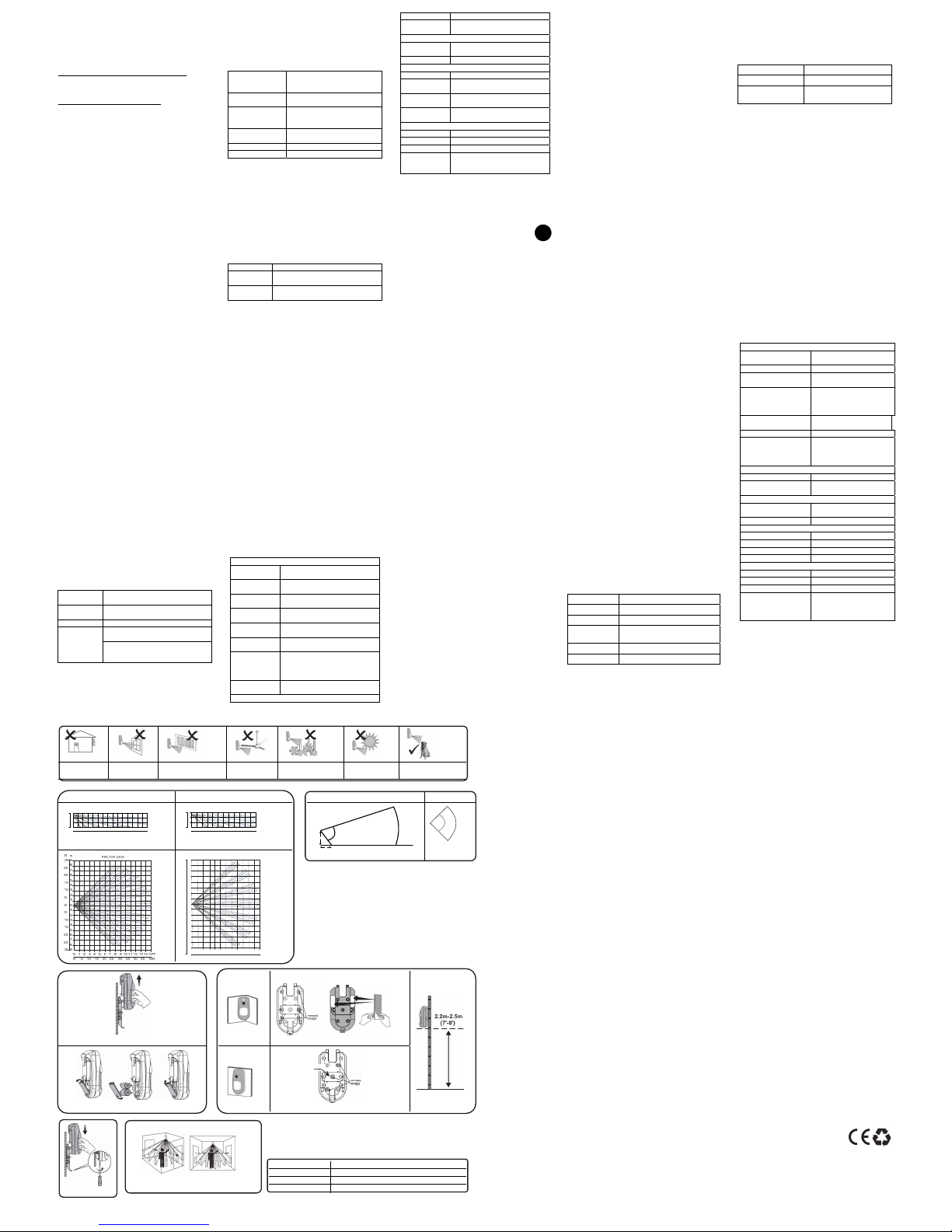
Preliminary Considerations
Do not install
outside
Do not install
near windows
Do not install near vents
(air, heat, or AC)
Do not install
near ceiling fans
Do not install in
extreme temperatures
Do not install in
direct sunlight
Ok for sites with small
pets
PIR Coverage Patterns
Camera FOV
PIR Model Pet Friendly Model
Side View Top View
ft.
1 2 3 45 67 8 9101112131415
1
2
0
3
01052015 3025 4035
5045
0
10
5
PIR -SIDE VIEW
m
m
ft
ft m
ft
m123456789101112
1
2
0
3
01052015 3025 4035
0
10
5
PIR Pet -SIDE VIEW
Figure 1
Figure 2
Figure 3
Figure 4
Figure 5
* Used for back tamper / Utilisé pour l’autoprotection arrière /
Utilizzato per il tamper anti-rimozione / Usado por el tamper
trasero / Används för sabotagekontakt mot vägg
Ordering Information
RWX95CM8000B 868.65 MHz 2-Way WL PIR & CAM Detector
RWX95CMP800B 868.65 MHz 2-Way WL PIR Pet & CAM Det.
RWX95CM4000B 433.92 MHz 2-Way WL PIR & CAM Detector
RWX95CMP400B 433.92 MHz 2-Way WL PIR Pet & CAM Det.
Standard Limited Product Warranty
RISCO Ltd., its subsidiaries and affiliates (“Risco") guarantee Risco’s hardware products to be free from defects in materials and workmanship
when used and stored under normal conditions and in accordance with the instructions for use supplied by Risco, for a period of (i) 24 months
from the date of connection to the Risco Cloud (for cloud connected products) or (ii) 24 months from production (for other products which are
non-cloud connected), as the case may be (each, the “Product Warranty Period” respectively).
Contact with customers only. This Product Warranty is solely for the benefit of the customer who purchased the product directly from Risco, or from any authorized distributor
of Risco. Nothing in this Warranty obligates Risco to accept product returns directly from end users that purchased the products for their own use from Risco’s customer or
from any installer of Risco, or otherwise provide warranty or other services to any such end user. Risco customer shall handle all interactions with its end users in connection
with the Warranty, inter alia regarding the Warranty. Risco’s customer shall make no warranties, representations, guarantees or statements to its customers or other third
parties that suggest that Risco has any warranty or service obligation to, or any contractual privy with, any recipient of a product.
Return Material Authorization. In the event that a material defect in a product shall be discovered and reported during the Product Warranty Period, Risco shall, at its option,
and at customer's expense, either: (i) accept return of the defective Product and repair or have repaired the defective Product, or (ii) accept return of the defective Product and
provide a replacement product to the customer. The customer must obtain a Return Material Authorization (“RMA”) number from Risco prior to returning any Product to
Risco. The returned product must be accompanied with a detailed description of the defect discovered (“Defect Description”) and must otherwise follow Risco’s then-current
RMA procedure in connection with any such return. If Risco determines in its reasonable discretion that any Product returned by customer conforms to the applicable warranty
(“Non-Defective Products”), Risco will notify the customer of such determination and will return the applicable Product to customer at customer’s expense. In addition, Risco
may propose and assess customer a charge for testing and examination of Non-Defective Products.
Entire Liability. The repair or replacement of products in accordance with this warranty shall be Risco’s entire liability and customer’s sole and exclusive remedy in case a
material defect in a product shall be discovered and reported as required herein. Risco’s obligation and the Warranty are contingent upon the full payment by customer for such
Product and upon a proven weekly testing and examination of the product functionality.
Limitations. The Product Warranty is the only warranty made by Risco with respect to the Products. The warranty is not transferable to any third party. To the maximum extent
permitted by applicable law, the Product Warranty does not apply and will be void if: (i) the conditions set forth above are not met (including, but not limited to, full payment
by customer for the product and a proven weekly testing and examination of the product functionality); (ii) if the Products or any part or component thereof: (a) have been
subjected to improper operation or installation; (b) have been subject to neglect, abuse, willful damage, abnormal working conditions, failure to follow Risco’s instructions
(whether oral or in writing); (c) have been misused, altered, modified or repaired without Risco’s written approval or combined with, or ipnstalled on products, or equipment
of the customer or of any third party; (d) have been damaged by any factor beyond Risco’s reasonable control such as, but not limited to, power failure, electric power surges, or
unsuitable third party components and the interaction of software therewith or (e) any delay or other failure in performance of the product attributable to any means of
communications, provided by any third party service provider (including, but not limited to) GSM interruptions, lack of or internet outage and/or telephony failure.
BATTERIES ARE EXPLICITLY EXCLUDED FROM THE WARRANTY AND RISCO SHALL NOT BE HELD RESPONSIBLE OR LIABLE IN RELATION THERETO, AND THE
ONLY WARRANTY APPLICABLE THERETO, IF ANY, IS THE BATTERY MANUFACTURER'S WARRANTY.
Risco makes no other warranty, expressed or implied, and makes no warranty of merchantability or of fitness for any particular purpose. For the sake of good order and
avoidance of any doubt:
DISCLAIMER. EXCEPT FOR THE WARRANTIES SET FORTH HEREIN, RISCO AND ITS LICENSORS HEREBY DISCLAIM ALL EXPRESS, IMPLIED OR STATUTORY, REPRESENTATIONS, WARRANTIES,
GUARANTEES, AND CONDITIONS WITH REGARD TO THE PRODUCTS, INCLUDING BUT NOT LIMITED TO ANY REPRESENTATIONS, WARRANTIES, GUARANTEES, AND CONDITIONS OF
MERCHANTABILITY, FITNESS FOR A PARTICULAR PURPOSE, TITLE AND LOSS OF DATA. WITHOUT LIMITING THE GENERALITY OF THE FOREGOING, RISCO AND ITS LICENSORS DO NOT REPRESENT
OR WARRANT THAT: (I) THE OPERATION OR USE OF THE PRODUCT WILL BE TIMELY, SECURE, UNINTERRUPTED OR ERROR-FREE; (ii) THAT ANY FILES, CONTENT OR INFORMATION OF ANY KIND
THAT MAY BE ACCESSED THROUGH THE PRODUCT BY CUSTOMER OR END USER SHALL REMAIN SECURED OR NON DAMAGED. CUSTOMER ACKNOWLEDGES THAT NEITHER RISCO NOR ITS
LICENSORS CONTROL THE TRANSFER OF DATA OVER COMMUNICATIONS FACILITIES, INCLUDING THE INTERNET, GSM OR OTHER MEANS OF COMMUNICATIONS AND THAT RISCO’S PRODUCTS,
MAY BE SUBJECT TO LIMITATIONS, DELAYS, AND OTHER PROBLEMS INHERENT IN THE USE OF SUCH MEANS OF COMMUNICATIONS. RISCO IS NOT RESPONSIBLE FOR ANY DELAYS, DELIVERY
FAILURES, OR OTHER DAMAGE RESULTING FROM SUCH PROBLEMS.
RISCO WARRANTS THAT ITS PRODUCTS DO NOT, TO THE BEST OF ITS KNOWLEDGE, INFRINGE UPON ANY PATENT, COPYRIGHT, TRADEMARK, TRADE SECRET OR OTHER INTELLECTUAL PROPERTY
RIGHT
IN ANY EVENT RISCO SHALL NOT BE LIABLE FOR ANY AMOUNTS REPRESENTING LOST REVENUES OR PROFITS, PUNITIVE DAMAGES, OR FOR ANY OTHER INDIRECT, SPECIAL, INCIDENTAL, OR
CONSEQUENTIAL DAMAGES, EVEN IF THEY WERE FORESEEABLE OR RISCO HAS BEEN INFORMED OF THEIR POTENTIAL.
Risco does not install or integrate the product in the end user security system and is therefore not responsible for and cannot guarantee the performance of the end user security
system which uses the product.
Risco does not guarantee that the product will prevent any personal injury or property loss by burglary, robbery, fire or otherwise; or that the product will in all cases provide
adequate warning or protection. Customer understands that a correctly installed and maintained alarm may only reduce the risk of burglary, robbery or fire without warning,
but is not an assurance or a guarantee that such an event will not occur or that there will be no personal injury or property loss as a result thereof. Consequently Risco shall have
no liability for any personal injury, property damage or loss based on a claim that the product fails to give warning. No employee or representative of Risco is authorized to
change this warranty in any way or grant any other warranty.
Contacting RISCO Group
RISCO Group is committed to customer service and product support. You can con tact us through our website (www.riscogroup.com) or at the following telephone and fax
numbers:
United Kingdom
Tel: +44-(0)-161-655-5500
support-uk@riscogroup.com
Belgium (Benelux)
Tel: +32-2522-7622
support-be@riscogroup.com
Spain
Tel: +34-91-490-2133
support-es@riscogroup.com
France
Tel: +33-164-73-28-50
support-fr@riscogroup.com
Italy
Tel: +39-02-66590054
support-it@riscogroup.com
USA
Tel: +1-631-719-4400
support-usa@riscogroup.com
Israel
Tel: +972-3-963-7777
support@riscogroup.com
China (Shanghai)
Tel: +86-21-52-39-0066
support-cn@riscogroup.com
Australia
Tel: + 542-991-1800
support-au@riscogroup.com
All rights reserved. No part of this document may be reproduced in any form without prior written permission from the publisher.
© RISCO Group 10/2017 5IN2446 D
1
0
m
70°
D
D
90°
10m
ft m
PIR Pet -TOP VIEW
0
10
5
20
15
25
1
2
3
4
5
6
7
8
0
10
5
20
15
30
25
1
2
3
4
5
6
7
8
9
01052015 3025 4035
1234567891011120
D = 2,4 m
SE
*
 Loading...