

Risco CSMDTN with EUT description
GENERAL DESCRIPTION
The COSMOS family includes the following models:
COSMOS PR: A microprocessor based Passive Infrared detector
•
COSMOS AM: Passive Infrared detector with anti-masking features.
•
COSMOS PET PR: A microprocessor based Passive Infrared detector with
•
pet immunity
COSMOS PQ: A Quad PIR with two separate dual element pyroelectric
•
sensors.
COSMOS DT: A Dual Technology detector offering both MW and IR
•
technologies.
COSMOS DTAM: A Dual Technology detector with anti-masking features.
•
COSMOS PET DT: A Dual Technology detector with pet immunity.
•
COSMOS DT FEATURES
Dual IR and MW Technologies
•
Creep Zone
•
Microprocessor Design
•
Automatic True Temperature Compensation
•
Microwave Range Adjustment
•
Pigmented Lenses
•
Alternate Polarity Pulse Count
•
Low Current Consumption
•
High RFI Immunity
•
Anti-Fluorescent Interference Signal Processing
•
Wall and Corner Mounting Without Accessories
•
Vertical Adjustment
•
UL Listed Versions
•
CAUTION:
THE UNIT SHOULD NOT BE MOUNTED IN DIRECT SUNLIGHT OR NEAR
ANY HEAT SOURCES. THE DETECTION SECTORS SHOULD BE POINTED
TOWARDS EITHER A WALL OR THE FLOOR (NOT WINDOWS AND
CURTAINS). INSTALL ON SMOOTH SURFACES ONLY.
STEP 2
If a fixing screw is used to secure the front cover, turn the screw 3 full turns
in the counterclockwise direction. With the screw now loosened, press it in
to release the front cover.
If a screw is not used, press the tab located behind the screw hole. The front
cover can now be removed.
PRELIMINARY CONSIDERATIONS
The cosmos DT is available in the following versions:
DTI (UK) (10.687 GHz)
RK - 210DTI
RK - 215DTI
RK - 225DTI
The IR responds to changes in the ambient thermal radiation caused when
an intruder crosses the protected area.
The MW transmits signals and analyzes the frequency changes of the
reflected echo from an intruder due to Doppler effect.
An ALARM is initiated only when both technologies trigger simultaneously.
Detection occurs only in areas where IR and MW patterns overlap, greatly
reducing the chance of false alarms.
Table 1: Available COSMOS DT Lenses and Accessories.
ACCESSORY
Typical Mounting Height 2.5m 2.5m 2m
Wide Angle Lens RL-115 RL-125
Long Range Lens *** *** RL-17
Corridor Lens RL-15 ***
Pet Alley set RA-12 ***
Ceiling Mounted Swivel RA-90 ***
Wall/Corner Mounted Swivel RA-91 ***
RANGE
10m/ 33ft
15m/ 50ft
25m/ 80ft
RK-225 RK-215 RK-210
1 2 3
FCC (USA)
(10.525 GHz)UL Listed
RK - 210FC
RK - 215FC
RK - 225FC
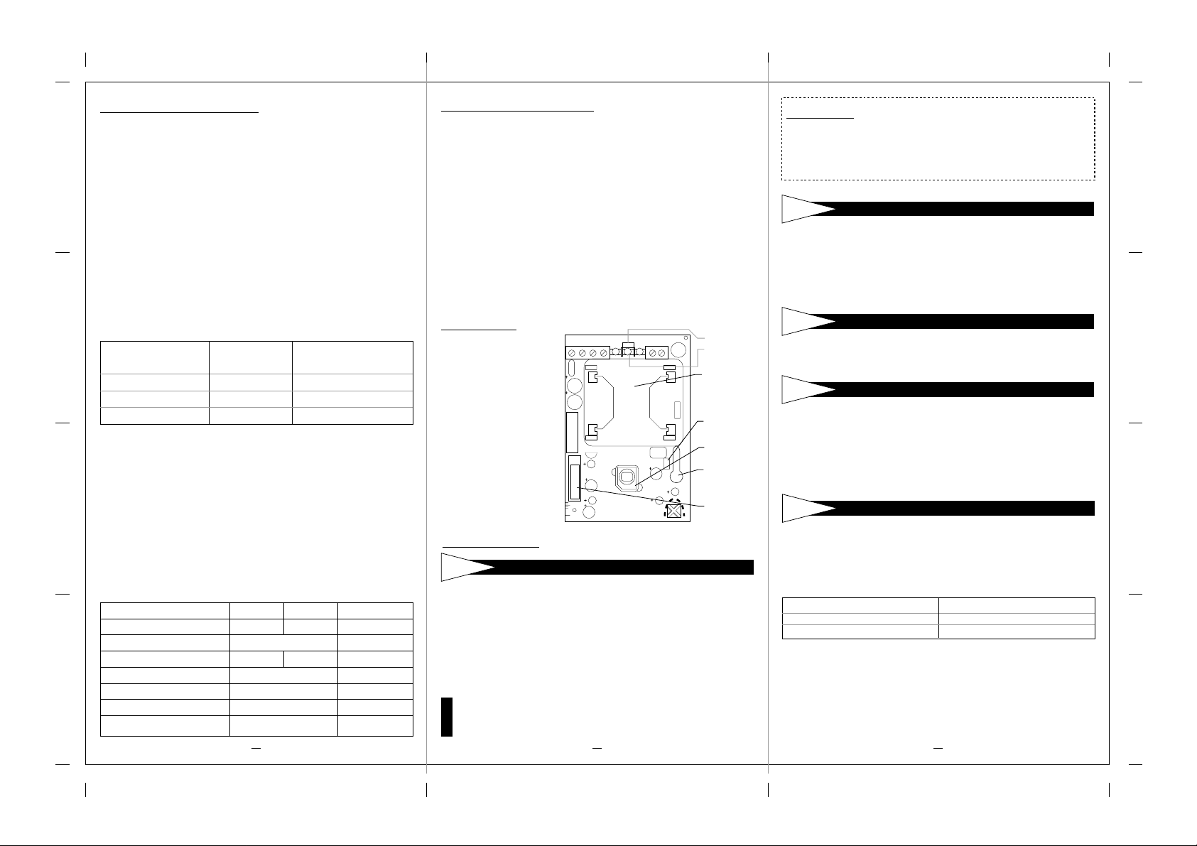
LED display
When LEDS Jumper is IN:
YELLOW LED indicates
•
PIR detection
GREEN LED indicates
•
MW detection
RED LED indicates alarm
•
(simultaneous PIR and
MW detection)
At Powe-up period, the
•
Leds will blink
continuously, one after
the other, untill end of
warm-up period.
TAMPER+ - LEDS ON ALARM C29
+5V
MU1
C15
C28
IF
1 T4
C19
S1
C6
C25
LONG
C8
SHORT
TC1
PULSE
C1
MICROWAVE
SENSITIVITY
OFF
C24
MIN MAX
LED's jumper
+
LEDS
GND
MW
Module
XTL1
PULSE
Jumper
GND
IR Sensor
MW Range
Adjustment
C21
Tamper
Switch
INSTALLATION
STEP 1
Before installation, carefully study the space to be protected so as to choose
the correct placement of the unit and lens for best coverage.
The detector should be installed so that the beam patterns are at 45º
(optimal) to the intruder's expected path. Corner installations are
recommended. Installation height should be between 1.8m (5’9”) and 2m
(6’7”) for the 225 and at an optional 2.5m (8’2”) for the RL-17. Use Fig 3
as reference.
The IR range is determined by the installation height. Use fig 3 as a
reference. For every 10cm (4") of lowering (or increasing) the
NOTE
installation height, the range is reduced (or increased) by 2.8m (9'2").
PRELIMINARY CONSIDERATIONS
STEP 3
Loosen the holding screw located on the right side of the PCB and slide the PCB
up until the screw enters the widened region. The PCB can now be lifted off.
STEP 4
The COSMOS DT can be mounted either on flat surface or at corner.
a. Open the knockout holes on the rear cover.
b. Insert the cable through the cable hole.
c. Mount the rear cover in its final location.
d. Seal the remaining holes with sealant.
e. After mounting the back cover replace the PCB in its position.
STEP 5
After the Detector base has been mounted, reinstall the PCB. Use the scale
on the bottom left side of the PCB to choose the correct vertical adjustment
position as follows:
For WIDE ANGLE LENS RK210/RK 215
installed at a height of 2.5m (8’2”) (for UL).
RK-225 install at 2m (6’7”) at Long position only
Fine Tuning of Protected Area:
Slide the board up - to lower the beams and reduce the range.
Slide the board down - t o raise the beams and increase the range.
For LONG RANGE: Select select position, LONG, Pulse Count of 1 and a
mounting height of 2.5m.
When completed, fasten the screw to secure the PCB in the desired position.
PC BOARD REMOVAL
MOUNTING
PC BOARD ADJUSTMENT
SCALE POSITION
short
long
ROOM SIZE
3-6m (9-18ft)
6-15m (18-50ft)
STEP 6
TERMINAL WIRING
Wire cable to the terminal block at the top of the PCB as follows:
12 VDC: Power supply input.
ALARM: Nor maly closed output.
TAMPER: Normaly closed dr y output.
STEP 7
JUMPER SETTING
The COSMOS DT has two jumpers that can be either IN (used) or
OUT (unused).
Unused jumpers should be placed on one leg only to prevent their loss.
Fig 2: Jumper positions.
IN
OUT
LEDS: IN - Enables all LEDs
OUT - Disables all LEDs
PULSE: IN - NO Pulse Count (1 pulse)
OUT -Alternative Polarity Pulse Count (2 pulses)
STEP 8
WALK TEST
Two minutes after applying power (a warm-up period), walk test the detector
over the entire protected area to verify proper operation of the unit.
The RK-225 needs a longer warm-up period of FOUR minutes. It enables a
powerful long range sensing capability and has increased sensitivity.
Make sure to replace front cover before Walk Test.
•
The MW range can be adjusted using the potentiometer located at the
•
bottom of the PCB. It is important to set the potentiometer to the lowest
possible setting that will still provide coverage for the entire
NOTE
protected area.
ROKONET LIMITED WARRANTY
Rokonet Electronics, Ltd. and its subsidiaries and affiliates ("Seller") warrants its products to be free from defects in materials
and workmanship under normal use for 24 months from the date of production. Because Seller does not install or connect
the product and because the product may be used in conjunction with products not manufactured by the Seller, Seller can
not guarantee the performance of the security system which uses this product. Sellers obligation and liability under this
warranty is expressly limited to repairing and replacing, at Sellers option, within a reasonable time after the date of delivery,
any product not meeting the specifications. Seller makes no other warranty, expressed or implied, and makes no warranty
of merchantability or of fitness for any particular purpose. In no case shall seller be liable for any consequential or incidental
damages for breach of this or any other warranty, expressed or implied, or upon any other basis of liability whatsoever.
Sellers obligation under this warranty shall not include any transportation charges or costs of installation or any liability for
direct, indirect, or consequential damages or delay.
Seller does not represent that its product may not be compromised or circumvented; that the product will prevent any persona;
injury or property loss by burglary, robbery, fire or otherwise; or that the product will in all cases provide adequate warning
or protection. Buyer understands that a properly installed and maintained alarm may only reduce the risk of burglary,
robbery or fire without warning, but is not insurance or a guaranty that such will not occur or that there will be no personal
injury or property loss as a result.
Consequently seller shall have no liability for any personal injury, property damage or loss based on a claim that the product
fails to give warning. However, if seller is held liable, whether directly or indirectly, for any loss or damage arising from
under this limited warranty or otherwise, regardless of cause or origin, sellers maximum liability shall not exceed the purchase
price of the product, which shall be complete and exclusive remedy against seller.
No employee or representative of Seller is authorized to change this warranty in any way or grant any other warranty.
WARNING: This product should be tested at least once a week.
4
STEP 9
FINAL SETUP
After completing the installation and testing stages, ensure all jumpers
are at their desired positions. The unit is now ready for normal use.
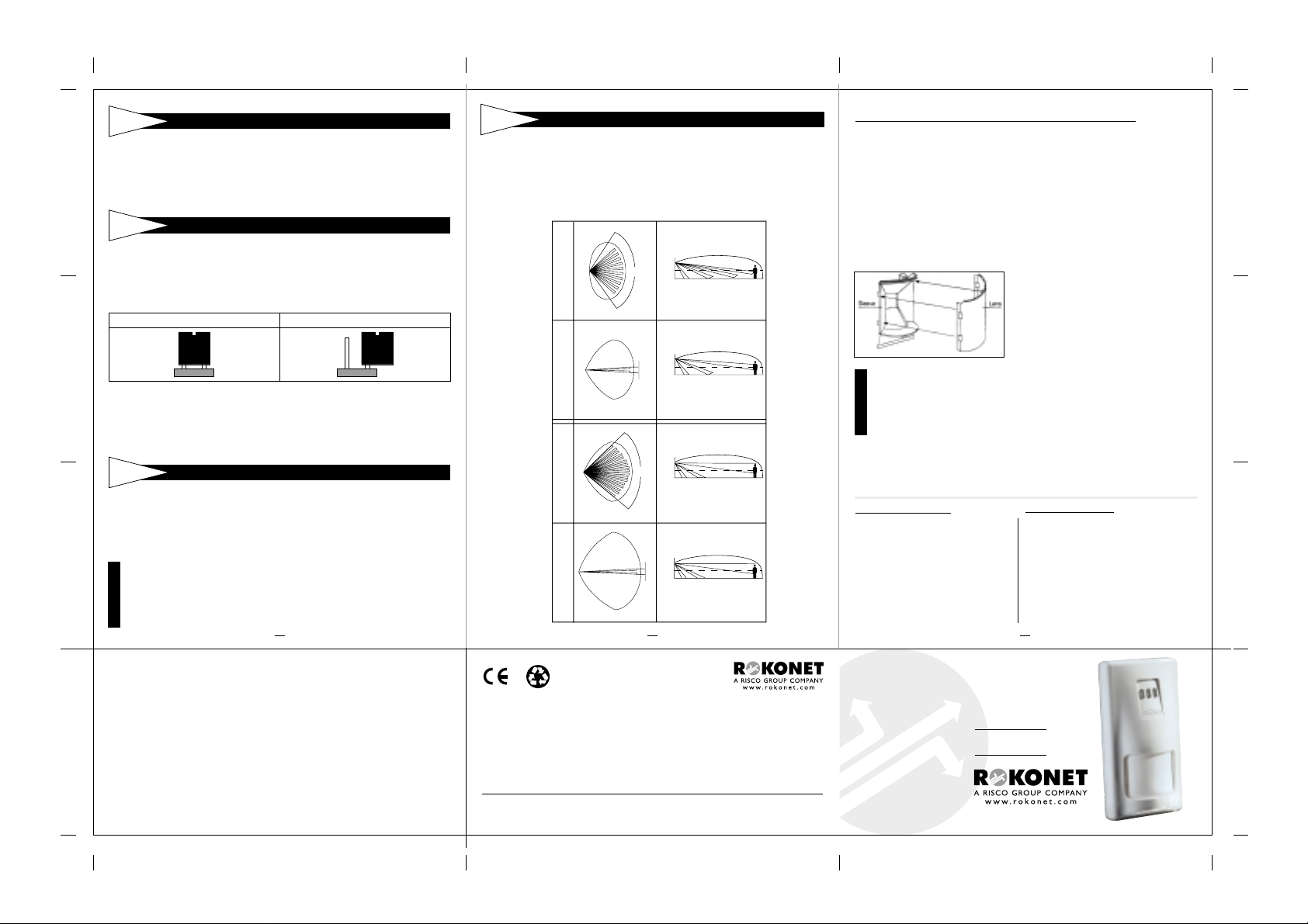
Fig 3: Cosmos DT Lenses
TOP VIEW SIDE VIEW
2.5m
(8'2")
RK-210/215
WIDE ANGLE (RL-115)
RK-210/215
CORRIDOR (RL-15)
WIDE ANGLE
RK-225 RL-125
LONG RANGE
RK-225 (RL-17)
110
0.4m
(1'4")2m(6'7")5m(16'5")
2.5m
(8'2")
1.1m
1.3m
(3'3")
/2m
0.4m
(1'4")
2m
(6'7")
1.1m
83
(3'3")
0.4m
(1'4")3m(9'10")
2.5m
(8'2")
1.1m
3m
(3'3")
0.4m
(1'4")4m(13'1")
(8'2")
10m/15m
(33/49')
2.5m
10m/15m
(33/49')
25m
(82')
23m
(75'5")
5 6
ROKONET ELECTRONICS LTD.
14 HACHOMA ST.
75655 RISHON LETZION. ISRAEL.
TEL: (972) 3 961 6555 FAX: (972) 3 961 6584
ROKONET USA:
ROKONET UK:
ROKONET FRANCE:
ROKONET ITALY:
ROKONET BRAZIL:
© 2001 Rokonet Electronics Ltd
TEL: 1 914
TEL: 44 (0)
TEL: 33 (0)
TEL: 39 (02)
TEL: 55 (21)
592 1068
1527 576 765
155 123390
3925 354
496.3544
FAX: 1 914
FAX: 44 (0)
FAX: 33 (0)
FAX: 39 (02)
FAX: 55 (21)
592 1271
1527 576 816
148 863042
3925 131
496.3547
7in71fmb
05/01
PROCEDURE FOR CHANGING LENSES
The pigmented lens is attached to the inside of the front plastic cover using
a sensor protective sleeve.
1. Remove the sensor protecting sleeve by pushing up the clip that holds
the top part of the sleeve to the front cover.
2. Disconnect the lens from the sleeve by gently lifting it from the holding
pins that secure it to the sides of the sleeve.
3. Select the desired lens and make sure that the cut corners are pointed
upwards. (Fig. 4).
4. Place the two pins, located on the top and bottom part of the lens, into
the matching holes on the sleeve.
5. Place the holes on either side of the lens into their matching holding pins
on the sides of the sleeve.
6. Insert the protective sleeve back into place on the front cover.
Fig 4.
Lens Change
Procedure
This equipment has been tested and found to comply with the limits for a Class B digital device,
pursuant to part 15 of the FCC Rules. These limits are designed to provide reasonable protection
against harmful interference in a residential installation. This equipment generates, uses and can
radiate radio frequency energy and, if not installed and used in accordance with the instructions,
cause harmful interference to radio communications. However, there is no guarantee that interference
will not occur in a particular installation. If this equipment does cause harmful interference to radio
or television reception, which can be determined by turning the equipment on and off, the user is
NOTE
encouraged to try to correct the interference by one or more of the following measures:
Reorient or relocate the receiving antenna
•
Increase the separation between the equipment and the receiver
•
Connect the equipment into an outlet on a circuit different from that to which the receiver is connected
•
Consult the dealer or an experienced radio/TV technician for help.
•
Changes or modifications to this equipment not expressly approved by the party responsible for
compliance (Rokonet Electronics Ltd.) could void the user's authority to operate the equipment.
SPECIFICATIONS
ELECTRICAL
Current consumption: 19mA at 12 VDC
Voltage requirements: 9-16 VDC regulated
Alarm contacts: 24 VDC, 50 mA
Tamper contacts: 24 VDC, 0.1A
OPTICAL
Filtering: White Light Protection
PHYSICAL
Size: 127.6 x 64.2 x 40.9mm
ENVIRONMENTAL
Operating temperature: -10ºC to 55ºC (14ºF to 131ºF)
Storage Temperature: -20ºC to 60ºC (-4ºF to 140ºF)
45mA at 16 VDC
(MAX with all LED's ON)
(5 x 2.5 x 1.6 in.)
NOTES FOR UL
1. The models have been listed by Underwriters
Laboratories for use with the wide angle lens
only .
2. The detector is intended to be connected to
a listed burglar alarm control unit capable
of providing 4 hours of standby power.
Specifications are subject to change without prior notice.
Should any questions arise, contact your distributor.
COSMOS
DT SERIES
RK-210,215,225
INSTALLATION
INSTRUCTIONS
 Loading...