

Risco BWare RK515DTGL User Manual
© RISCO Group 01/2012 5IN1749
EN 50131-1
EN 50131-2-4
Grade 2
Environmental Class II
CE Compliance Section:
Risco Ltd. hereby declares that this equipment is in compliance with the essential
requirement and other relevant provisions of Directive 1999/5/EC.
For the EC Declaration of Conformity please refer to our website: www.riscogroup.com
U.S. Patent Number:
This product is protected under Patent No. US 7,126,476 B2.
Other patents pending.
RISCO Group Limited Warranty
RISCO Group and its subsidiaries and affiliates ("Seller") warrants its products to be free
from defects in materials and workmanship under normal use for 24 months from the date
of production. Because Seller does not install or connect the product and because the
product may be used in conjunction with products not manufactured by the Seller, Seller
cannot guarantee the performance of the security system which uses this product. Seller's
obligation and liability under this warranty is expressly limited to repairing and replacing, at
Seller's option, within a reasonable time after the date of delivery, any product not meeting
the specifications. Seller makes no other warranty, expressed or implied, and makes no
warranty of merchantability or of fitness for any particular purpose.
In no case shall seller be liable for any consequential or incidental damages for breach of
this or any other warranty, expressed or implied, or upon any other basis of liability
whatsoever.
Seller's obligation under this warranty shall not include any transportation charges or costs
of installation or any liability for direct, indirect, or consequential damages or delay.
Seller does not represent that its product may not be compromised or circumvented; that
the product will prevent any personal injury or property loss by burglary, robbery, fire or
otherwise; or that the product will in all cases provide adequate warning or protection.
Seller, in no event shall be liable for any direct or indirect damages or any other losses
occurred due to any type of tampering, whether intentional or unintentional such as
masking, painting or spraying on the lenses, mirrors or any other part of the detector.
Buyer understands that a properly installed and maintained alarm may only reduce the risk
of burglary, robbery or fire without warning, but is not insurance or a guaranty that such
event will not occur or that there will be no personal injury or property loss as a result
thereof.
Consequently seller shall have no liability for any personal injury, property damage or loss
based on a claim that the product fails to give warning. However, if seller is held liable,
whether directly or indirectly, for any loss or damage arising under this limited warranty or
otherwise, regardless of cause or origin, seller's maximum liability shall not exceed the
purchase price of the product, which shall be complete and exclusive remedy against
seller.
No employee or representative of Seller is authorized to change this warranty in any way
or grant any other warranty.
WARNING: This product should be tested at least once a week.
CAUTION: risk of explosion if battery is replaced by an incorrect type.
Dispose of used batteries according to local regulations.
RISCO Group Contacting Info
RISCO Group is committed to customer
service and product support. You can contact
us through our website (www.riscogroup.com)
or at the following telephone and fax numbers:
Mounting Height L - LONG S - SHORT
2.1m-2.7m (6'11"-8’10") 15m (50’) 6m (20’)
Terminal Description
- 12 + 12VDC Input
ALARM N.C. Relay
TAMPER N.C. Tamper switch
LED LED operation remote control
When an ”Activation Signal”** is applied to the LED input
terminal, all LEDs will be disabled.
LEDs are enabled if nothing is connected (unless LED
jumper is OFF) or 0V/12V is applied (according to the LED
Input Jumper position, 12V or 0V).
**Activation SignalIf 12VDC is applied, and the LED Input Jumper is on 12V position
(Default position)
- Or 0V is applied and LED Input Jumper is on 0V position
Jumper Settings
SW1-2: ACT Used to determine if ACT mode is enabled or disabled
ON
ACT Enabled
Important: Do not use ACT™ mode if you are expecting that
there will be moving objects outside the required protected area,
a corridor for example.
OFF
(Default)
ACT Disabled.
Jumper Function
SW1-1: LED Used to determine the operation of the detector’s LEDs
ON:
(Default)
LEDs are enabled, allowing LED control via the LED input
terminal
OFF: LEDs are disabled
Walk Test
1. Two minutes after applying power (warm-up period), walk test the
Detector over the entire protected area to verify proper operation of the
unit (see Figure 7).
2. The K-Band MW range must be adjusted using the potentiometer located
on the PCB. It is important to set the potentiometer to the lowest possible
setting that will still provide enough coverage for the inner boundary
protected area (see Figure 5).
Blue On ALARM
All LEDs
Flashing
consecutively
At power-up, the LEDs will flash consecutively until the
end of the warm-up period (2-3 minutes).
LEDs Display
LED State Description
Yellow On PIR detection
Flashing Trouble in PIR channel
Green On MW detection
Flashing Trouble in MW channel
Technical Specification
Electrical
Current consumption 16mA at 12VDC (typical)
41mA at 12VDC (max.)
Voltage requirements 9 -16VDC***
Alarm contacts 24VDC, 0.1A
Tamper contacts 24VDC, 0.1A
Environmental
RF immunity According to EN50130-4
Operating temperature -10ºC to 55ºC (14ºF to 131ºF)
Storage temperature -20ºC to 60ºC (-4ºF to 140ºF)
Optical
Filtering White Light Protection
Physical
Size 127.6 x 64.2 x 46.6 mm (5 x 2.5 x 1.84 in.)
Weight 120 gr. (4.2 oz.)
*** Power to be supplied by 5A max. power source using safety approved
wires, with a min Gauge of 20AWG.
SW1-4: Self Not applicable in this version.
Test
SW1-3: Green Line
The BWare DT includes a Green Line feature that follows environmental
guidelines. This feature disables the MW channel when the alarm system is
“Unset”, thus eliminating surplus MW emission while the premises is occupied.
ON
Green Line feature is enabled: To deactivate the MW module
during “UNSET”, the LEDs must also be remotely disabled by
the LED terminal.
Note: When ‘Green Line’ is on (Microwave off), the detector will
still activate (PIR only)
OFF
(Default)
Green Line feature in disabled: MW is constantly in use.
(Default)
J4 - LED
Used to determine the polarity of the external LED input.
INPUT
See Terminal Wiring section,
LED Terminal
See Terminal Wiring section,
LED Terminal
J1 - Alarm EOL
J2 - Tamper EOL
Jumpers J1 and J2 allow the selection of Tamper and Alarm
resistance (1K, 2.2K, 4.7K, 5.6K, 6.8K) according to the
control panel (see Figure 4).
.
Follow the terminal block connection diagram in Figure 4
when connecting the detector to a Double End Of Line
(DEOL) Zone.
ENGLISH
The BWare DT detector is the ultimate motion detector for professional
installations, incorporating Anti-Cloak™ Technologie (ACT™) and includes
built-in end-of-line (EOL) resistors to simplify installation.
The detector employs K-Band microwave providing reduced wall
penetration.
Installation / Maintenance
Mounting - The BWare DT can be mounted either on a flat surface or on a
wall corner (corner mounting).
1. Remove detector’s front cover using a suitable tool (as described in
Figure 1).
2. Using a suitable tool, open the following knockouts on the detector’s
base (see Figure 2).
3. To select the correct vertical adjustment position for wide angle lens,
use the scale on the bottom right hand side of the PCB cover as follows:
Mounting height and scale position based on room size:
4. Set jumpers (see Jumper Setting section).
Note: Reset the detector after each change made to the settings.
5. Install the front cover back to its place (in a reverse sequence of the
removal).
6. Perform a Walk test (see Walk Test section below).
Terminal Wiring (see Figure 5)
UK Tel: 44-(0)-161-655-5500
support-uk@riscogroup.com
ITALY Tel: +39-02-66590054
support-it@riscogroup.com
SPAIN Tel: +34-91-490-2133
support-es@riscogroup.com
FRANCE Tel: +33-164-73-28-50
support-fr@riscogroup.com
BELGIUM Tel: +32-2522-7622
support-be@riscogroup.com
U.S.A Tel: +1-631-719-4400
support-usa@riscogroup.com
BRAZIL Tel: +55-11-3661-8767
support-br@riscogroup.com
CHINA (Shanghai)
Tel: +86-21-52-39-0066
support-cn@riscogroup.com
CHINA (Shenzhen)
Tel: +86-755-82789285
support-cn@riscogroup.com
POLAND Tel: +48-22-500-28-40
support-pl@riscogroup.com
ISRAEL Tel: +972-3-963-7777
support@riscogroup.com
K-Band DT Grade 2
Model: RK515DTGL
LED Stato Descrizione
LED Stato Descrizione
Giallo Illuminato Rilevazione del canale PIR
Lampeggiante Anomalia del canale PIR
Verde Illuminato Rilevazione del canale MW
Lampeggiante Anomalia del canale MW
Blu Illuminato ALLARME
Tutti i LED
Lampeggianti
consecutivamente
All’alimentazione tutti i LED lampeggiano in
sequenza fino alla fine del periodo di
inizializzazione (2-3 minuti).
Specifiche Tecniche
Elettriche
Assorbimento di corrente 16mA a 12V− (Nominale)
41mA a 12V− (Massimo)
Alimentazione richiesta da 9V− a 16V−
Contatti di allarme 24V− 0.1A
Contatti Tamper 24V− 0.1A
Ambientali
Immunità RF Conforme alle norme EN50130-4
Temp. funzionamento da -10ºC a 55ºC
Temp. stoccaggio da -20ºC a 60ºC
Ottica
Filtro Protezione contro le luci bianche
Fisiche
Dimensioni 127.6 mm x 64.2 mm x 46.6 mm
Peso 120 gr.
Installazione / Manutenzione
Installazione - Il rivelatore BWare DT può essere installato sia su di una
superficie piana che ad angolo.
1. Rimuovere il coperchio del rivelatore utilizzando un attrezzo appropriato
(come descritto nella Figura 1).
2. Utilizzando uno strumento appropriato aprire i fori a sfondare, di seguito
elencati, della base del contenitore come illustrato in Figura 2.
3. Per selezionare la posizione corretta della scheda elettronica con la lente
grandangolo montata, usare i riferimenti ( LONG / SHORT) situati nella
parte inferiore destra della scheda elettronica seguendo le indicazioni
della tabella di seguito illustrata:
4. Predisporre i ponticelli e i microinterruttori (Vedere la sezione relativa).
Nota: Ad ogni modifica delle predisposizioni/regolazioni, effettuare sempre
un reset del rivelatore rimuovendo e applicando tensione.
5. Rimontare il coperchio frontale e stringere la vite di blocco coperchio.
6. Effettuare una prova di copertura (Sezione Prova di movimento vedere
in basso).
Cablaggio Morsettiera (vedere Figura 5)
Morsetto Descrizione
- 12 + Ingresso di alimentazione 12V
ALARM Relé N.C.
TAMPER Interruttore N.C.
LED Controllo remoto dei LED e funzione GREEN LINE (con
microinterruttore SW1-3 in posizione ON)
Quando viene applicato un ”Segnale di Attivazione”** al
morsetto LED, tutti i LED vengono disabilitati e, se il
microinterruttore GREEN LINE è in ON, la sezione
microonda viene disabilitata.
I LED sono abilitati se al morsetto LED non è collegato
niente (a meno che il ponticello LED sia estratto).
**Per Segnale di attivazione si intende quanto segue-
- Viene applicata una tensione 12 Vcc e il ponticello LED Input è nella
posizione 12V (posizione di default)
- Viene applicato un riferimento di alimentazione 0V e il ponticello LED
Input è nella posizione 0V
Prova di movimento (Walk Test)
1. Due o tre minuti dopo aver alimentato il rivelatore (inizializzazione)
effettuare la prova di copertura dell’area da proteggere verificando la
risposta del rivelatore tramite l’accensione dei LED (vedere Figura 7).
2. La portata della microonda va regolata tramite l’apposito potenziometro
situato sulla scheda elettronica. Regolare il potenziometro della
microonda al minimo possibile riferito all’area da proteggere
(vedere Figura 5).
Il rivelatore BWare DT è un rivelatore di movimento che integra le tecnologie
più avanzate per le installazioni professionali. Questo rivelatore include
quella Anti-Cloak™ (ACT™) ed ha le resistenze di fine linea integrate nel
circuito per semplificarne al massino l'installazione.
Il rivelatore BWare DT utilizza la microonda in banda K la quale consente
una penetrazione ridotta attraverso i muri.
ITALIANO
Altezza di installazione e regolazione scheda elettronica in funzione
dell’areadi copertura:
Altezza di installazione L - LONG S - SHORT
2.1m-2.7m 15m 6m
J4- LED Usato per impostare la polarità dei comandi di attivazione
per gli ingressi LED.
Posizionato sul lato 12V richiede come
comando di attivazione una tensione
positiva. Fare riferimento alla sezione
relativa il Cablaggio Morsettiera,
morsetto LED.
Posizionato su 0V richiede come
comando di attivazione un riferimento
negativo di alimentazione 0V. Fare
riferimento alla sezione relativa il
Cablaggio Morsettiera, morsetto LED.
Microint./Pontic. Funzione
Predisposizione microinterruttori e ponticelli
Predisposizione microinterruttori e ponticelli
Microint./Pontic. Funzione
SW1-2: ACT Usato per abilitare o disabilitare la funzione ACT.
ACT abilitato
Importante: Non usare la funzione ACT™ se nel luogo di
installazione del rivelatore si prevede movimento di oggetti
al di fuori dell’area protetta come, ad esempio, il movimento
di persone in un corridoio attiguo.
ACT disabilitato.
SW1-1: LED Usato per abilitare o disabilitare il funzionamento dei LED.
ON
(Default)
I LED sono abilitati ed è possibile anche controllarli via
comando remoto tramite l’ingresso LED.
OFF
ON
OFF
(Default)
I LED sono disabilitati. Non è possibile alcun controllo remoto.
SW1-4: Self Non applicabile in questa versione.
Test
SW1-3: Green Line
BWare DT include la funzione Green Line che evita emissioni radio superflue
nell’ambiente. Questa funzione disabilita il canale a microonda (MW) quando
il sistema di sicurezza è disinserito.
La funzione Green Line è abilitata: Per disabilitare la sezione
microonda (MW) a sistema DISINSERITO va applicato un
comando di attivazione al morsetto LED (0V o 12V in funzione
della polarità configurata tramite il ponticello LED/SET INPUT).
Anche i LED verranno in questo caso disabilitati. La sezione
microonda viene disabilitata in questo modo solo se al morsetto
SET non viene applicata alcuna tensione.
Nota: Quando la funzione Green Line è attiva (Microonda
spenta), il rivelatore si attiva usando la sola sezione ad
infrarossi (PIR).
La funzione Green Line è disabilitata. La sezione a
microonda (MW) è sempre accesa.
ON
OFF
(Default)
Ponticelli Per
resistenze EOL
I ponticelli J1 e J2 permettono la selezione dei valori resistivi
da assegnare ai circuiti di Tamper e di Allarme (1K, 2.2K,
4.7K, 5.6K, 6.8K) in funzione della centrale d’allarme
utilizzata (vedere la Figura 4 in basso).
Seguire lo schema di collegamento dei morsetti illustrato in
Figura 4 quando si vuole collegare il sensore ad una centrale
d’allarme usando il doppio bilanciamento resistivo (DEOL).
J1 - Alarm EOL
J2 - Tamper EOL
(Default)
Contains FCC ID UXS-IPM165F
BWare RK515DTGL FCC Compliance Section:
FCC Part 15 Note:
This equipment has been tested and found to comply with the limits for a Class B digital
device, pursuant to Part 15 of the FCC rules. These limits are designed to provide
reasonable protection against harmful interference in a residential installation. This
equipment generates, uses and can radiate radio frequency energy and, if not installed
and used in accordance with the instructions, may cause harmful interference to radio
communications.
However, there is no guarantee that interference will not occur in a particular installation.
If this equipment does cause harmful interference to radio or television reception, which
can be determined by turning the equipment off and on, the user is encouraged to try to
correct the interference by one or more of the following measures:
Reorient or relocate the receiving antenna.
Increase the separation between the equipment and receiver.
Connect the equipment to an outlet on a circuit different from that to which the
receiver is connected.
Consult the dealer or an experienced radio/TV technician.
FCC Warning:
The manufacturer is not responsible for any radio or TV interference caused by
unauthorized modifications to this equipment. Such modifications could void the
user's authority to operate the equipment.
Lorsqu'un ”Signal d'Activation”** est appliqué à l'entrée
LED du bloc des terminaux ou bornes de connexion, les
indicateurs LED se désactivent (cf. aussi l'entrée Test
automatique dans le tableau consacré au Réglagedes
cavaliers).
Les voyants LED sont activés si rien n'est relié (sauf si le
cavalier LED est éteint (OFF).
**Signal d'Activation-
Si une tension de 12VCC est appliquée et que le Cavalier d'entrée LED
est en position 12V (Défaut de position)
-Ou-
Si la Terre (GND) est reliée, le Cavalier d'entrée LED est en position 0V.
SW1-3: Green Line
Le BWare DT intègre la fonction Green Line, qui suit les recommandations
environnementales. Cette fonction désactive le canal hyper fréquence quand le
système d’alarme est désarmé, pour éliminer le surplus d’émissions HF quand
les locaux sont occupés.
Marche (ON)
La fonction Green Line est activée : Pour désactiver le module
HF pendant le désarmement, les LEDs doivent aussi être
désactivées par le terminal de connexion LED.
Note : Quand le Green Line est activé (HF désactivé), le
détecteur sera toujours actif (IRP seul).
Arrêt (OFF)
(Défaut)
Green Line désactivé (OFF): le canal HF est constamment activé.
Réglage des cavaliers
Cavalier Fonction
SW1-1: LED Définit le fonctionnement des indicateurs LED du détecteur.
Marche (ON)
(Défaut)
L'activation des indicateurs LED dépend du paramétrage du
contrôle à distance de leur fonctionnement (cf. § Câblage des
Terminaux, borne de connexion LED).
Arrêt (OFF)
Les indicateurs LED sont désactivés.
SW1-2: ACT Définit si le mode ACT est activé ou non
Marche (ON)
ACT activé.
Important ! N'utilisez pas le mode ACT™ dans une zone en
dehors de laquelle le passage d'objets en mouvement vous
paraît logique et attendu, un couloir par exemple.
Arrêt (OFF)
(Défaut)
ACT désactivé.
Les cavaliers J1 et J2 permettent de sélectionner les
résistances EOL (fin de ligne) d'Autoprotection, Alarme et
FAULT (1K, 2,2K, 4,7K, 5,6K, 6 et 8K) en fonction
de la centrale (cf. Figure 4 ci-dessous).
Suivez les indications du diagramme de connexion du bloc
des terminaux de la Figure 4 pour relier le détecteur à une
zone EOL Double (DEOL).
J1 - Alarm EOL
J2 - Tamper EOL
Toutes
diodes LED
Clignotante
l'une après
l'autre
Lors de la mise sous tension, les diodes LED
clignotent de manière ininterrompue, l'une après
l'autre, jusqu'à la fin de la séquence
d'échauffement (2 à 3 minutes).
Affichage LED
LED Position Signification
Jaune Allumée (ON) Détection IRP
Clignotante Panne de canal IRP
Verte Allumée (ON) Détection HF (hyperfréquence)
Clignotante Panne de canal HF
Bleu Allumée (ON) Indique une ALARME
Rétsistance de la boucle de Etat ouvert: plus que 10
8
Détection:
Etat fermé: moins que 1 ohm
Ondulations résiduelles maximales
0.25 créte à créte
admissibles:
Taille du càble à utiliser: Fil de diamétre au moins 0.5 mm pour une
longueur ne dépassant pas 300 métres
Filtrage Protection anti-lumière blanche
Dimensions 127.6 x 64.2 x 46.6 mm (5 x2.5 x 1.84 in.)
Poids 120g
Immunité RF Selon EN50130-4
Température de fonctionnement De -20ºC à 55ºC (-4ºF à 131ºF)
Température de stockage De -20ºC à 60ºC (-4ºF à 140ºF)
Indice de protection: IP 31/IK 02
Spécifications techniques
Consommation électrique 14.8 mA à 12VCC (en utilisation typique)
39.5 mA à 12VCC (max. avec tous les
voyants LED allumés)
Tension requise 9 -16VCC
Contacts d'alarme 24VCC, 0,1A
Temps minimal de changement 2.2 seconds
d’état:
Contacts d'autoprotection 24VCC, 0,1A
Electriques
Test de passage
1. Deux minutes après avoir réalisé la mise sous tension (séquence
d'échauffement), effectuez un test de passage pour vérifier l'efficacité
du détecteur sur la totalité de la zone à protéger.
2. Assurez-vous d'avoir bien réinstallé le couvercle frontal avant de mettre
le détecteur sous tension (cf. Figure 7).
3. Le potentiomètre situé sur la carte PCB permet de régler la portée de
détection hyperfréquence. Il est important de régler le potentiomètre
sur le niveau le plus bas possible qui fournira cependant une couverture
suffisante sur la totalité de la zone à protéger (cf. Figure 5).
J4 - Entrée
LED
Détermine la polarité de l'entrée externe LED.
Cf. § Câblage de Terminal, borne de
connexion LED (Mise en service).
Cf. § Câblage de Terminal, borne de
connexion LED (Mise en service).
SW1-4: Test Non applicable dans cette version.
automatique
Câblage des Terminaux (cf. Figure 5)
Terminal Description
- 12 + Entrée 12VCC
ALARM Relais N.F., 24VCC, 0,1A
TAMPER Relais N.F., 24VCC, 0,1A
LED Contrôle à distance des indicateurs LED
Hauteur de montage L - LONG C - COURT (SHORT)
2.1m-2.7m (6'11"-8’10") 15m (50’) 6m (20’)
Hauteur de montage et position selon la taille de la pièce :
4. Réglez les cavaliers (cf. § Réglage des cavaliers).
Remarque: Il est conseillé de réinitialiser le détecteur après chaque
modification apportée au réglage.
5. Replacez le couvercle frontal (en inversant pour cela l'ordre des
étapes de la procédure de retrait).
6. Exécutez un test de passage (cf. §Test de passage ci-dessous).
FRANÇAIS
Le détecteur BWare DT est le dernier détecteur de mouvements pour
les installations professionnelles, et intègre les technologie
Anti-Camouflage (ACT™) ainsi que des résistances de fin de ligne
(EOL) pour simplifier l’installation.
Le détecteur utilise un module Hyper Fréquence en bande K, qui
permet une réduction de la pénétration à travers les murs.
Installation
Montage - l’BWare DT peut être installé soit sur une surface plane soit
en coin (gauche ou droit).
1. Retirer le détecteur de couvercle frontal a l’aide d'un outil adequat
(décrit son la Figure 1).
2. A l’aide d’un outil adequat, ouvrez les pastilles pré-percées
correspon dantes sur la báse du d tecteur (cf.Figure 2).
3. Pour définir le bon réglage vertical, positionnez l'appareil en
LENTILLE GRAND ANGLE.
Servez-vous de l'échelle figurant sur le côté inférieur droit de la carte
PCB de couvercle (cf. Figure 7) comme suit :
(Défaut)
Environnementales
Optiques
Physiques
Installatie / Onderhoud
Montage - De BWare DT kan op een vlakke oppervlakte worden
gemonteerd, of op een muurhoek (hoekmontage)
1. Verwijder het voorste lid met het juiste gereedschap (zoals beschreven
in Afbeelding 1).
2. Met een passend gereedschap opent u de volgende uitwerpers op
de basis van de detectore (zi Afbeelding 2).
3. Om voor de brede hoeklens de juiste verticale afstelpositie te selecteren,
gebruikt u de schaal op de rechts onderkant van de PCB lid. U doet dit
als volgt:
Montagehoogte en schaalpositie op basis van kamergrootte:
Montagehoogte L - LANG C - KORT
2.1m-2.7m 15m 6m
Opmerking: Voor installaties in een hal selecteert u de positie naar
'LANG' en monteert u de detector op een hoogte van 2,5 m/8'2".
4. Jumpers instellen (zie sectie Jumperinstellingen).
Opmerking: Na elke wijziging aan de instellingen, moet de detector
opnieuw ingesteld worden.
5. Installeer het voorste lid terug op zijn plaats (in omgekeerde volgorde van
de verwijdering).
6. Voer een looptest uit (zie sectie Looptest hieronder).
Bedrading terminal (zie Afbeelding 5)
Terminal Beschrijving
- 12 + 12 VDC-ingang
ALARME N.C.-relais
TAMPER N.C. Sabotageschakelaar
LED LED-werking afstandsbediening
Als op de LED van de ingangterminal een
"Activeringsignaal"** wordt toegepast, worden alle LED's
uitgeschakeld. LED's worden ingeschakeld als niks is
aangesloten (tenzij LED-jumper op UIT is ingesteld)
of 0V/12V wordt toegepast (volgens de LED positie van de
ingangjumper, 12 V of 0 V).
Looptest
1. Twee minuten na het toepassen van voeding (opwarmingsperiode),
voert u over het hele beschermde gebied van de detector de looptest
uit om goede werking van de eenheid te verifiëren (zie Afbeelding 7).
2. Het MW-bereik kan worden afgesteld door de potentiometer op de
PCB te gebruiken. Het is belangrijk dat de potentiometer op de laagst
mogelijke instelling wordt ingesteld om het binnenste beschermde
grensgebied voldoende dekking te bieden (zie Afbeelding 5).
Groen Aan MW-detectie
Knipperen Storing in MW-kanaal
Blauw Aan ALARM
Alle LED's Knipperen
achtereenvolgende
Bij het opstarten, zullen de LED’S
achtereenvolgens knipperen tot het einde van
de opwarmperiode (2-3 minuten).
Technische specificaties
Elektrisch
Stroomverbruik 16mA bij 12VDC (typisch)
41mA bij 12VDC (max.)
Spanningsvereisten 9 -16VDC
Alarmcontacten 24VDC, 0,1A
Sabotagecontactencontacten
24VDC, 0,1A
Omgeving
RF-immuniteit Volgens EN50130-4
Bedrijfstemperatuur -10ºC tot 55ºC
Opslagtemperatuur -20ºC tot 60ºC
Optisch
Filtrering Wit licht-bescherming
Fysiek
Grootte 127,6 x 64,2 x 46,6 mm
Gewicht 120 gr.
Display LED's
LED Status Beschrijving
Geel Aan PIR-detectie
Knipperen Storing in PIR-kanaal
De Bware DT detector is de ultieme bewegingsmelder voor professionele
installaties, met integratie technologie Anti-Cloak™ (ACT™) met
ingebouwde end-of-line (EOL) weerstanden voor een eenvoudige
installatie.
De detector maakt gebruik van de K-Band microwave om muur penetratie
te verminderen.
NEDERLANDS
Als 12 VDC wordt toegepast en de ingangjumper LED is op de positie
12V (standaardpositie)
-Of-
0 V wordt toegepast en ingangjumper LED is op positie 0 V
**Activeringsignaal-
Jumperinstellingen
Jumper Functie
SW1-2: ACT Gebruikt om vast te stellen of de ACT-modus is in- of
uitgeschakeld.
AAN
ACT ingeschakeld
Belangrijk: Niet de ACT™-modus gebruiken als u verwacht dat
er buiten het beschermde gebied (zoals bijvoorbeeld een hal,
bewegende objecten zijn.
UIT
(Standaard)
ACT uitgeschakeld.
SW1-1: LED Gebruikt om de werking van de LED's van de detector
vast te stellen.
AAN
(Standaard)
LED's worden ingeschakeld zodat via de ingangsterminal van
de LED, LED-besturing mogelijk is.
UIT
LED's worden uitgeschakeld
SW1-4: Zelf Niet van toepassing in deze versie.
Test
Jumpers J1 en J2 maken de selectie mogelijk voor
sabotage en alarmweerstand (1K, 2.2K, 4.7K, 5.6K, 6.8K)
volgens het bedieningspaneel (zie Afbeelding 4).
Volg het aansluitingsschema van het aansluitblok in
Afbeelding 4 als u de detector op een tweevoudige zone
aan het einde van de lijn (DEOL) aansluit.
J1 - Alarm EOL
J2 - Sabotage
EOL
J4 - LED Gebruikt om de polariteit van de externe LED ingang vast
te stellen.
SW1-3: Groene lijn
De Bware DT bevat de Groene lijn functie die milieurichtlijnen volgt door een
overschot uitstraling te vermijden. Deze functie schakelt het MW-kanaal uit als
het alarmsysteem “uitgeschakeld” is en dus de overmatige MW-uitstraling
vermijdt wanneer het gebied bezet is.
AAN
Groene lijn functie is ingeschakeld: om de MW-module in de
periode "Uitgeschakeld" te deactiveren, moeten ook de LED’S
van op afstand door de LED-terminal worden uitgeschakeld.
Opmerking: Als de 'Groene lijn' functie aan is (microgolf uit), is
de detector nog steeds actief (enkel PIR).
UIT
(Standaard)
Functie Groene lijn is uitgeschakeld: MW is constant in gebruik
(Standaard)
Zie de sectie Bedrading terminal,
terminal LED
Zie de sectie Bedrading terminal,
terminal LED
Configuración de los Puentes
Puente Función
Cableado del Terminal (ver Figura 5)
Terminal Descripción
- 12 + Entrada de 12VCC
ALARM Relé N.C.
TAMPER Interruptor del Tamper N.C.
**Señal de Activación-
Si se aplican 12VCC, y el puente (jumper) LED INPUT está en la posición
12V (posición por defecto)
O
Se aplican 0V y el puente (jumper) LED INPUT está en la posición 0V.
LED Control remoto del funcionamiento del LED
Cuando se aplica una ”Señal de Activación”** al terminal de
entrada del LED, se desactivan todos los LEDs.
Los LEDs se activan si no hay nada conectado (a menos
que el puente del LED esté en OFF) o se aplican 0V/12V
(según la posición del Puente LED Input, 12V ó 0V)
Instalación / Mantenimiento
Montaje - El BWare DT puede montarse en una superficie plana o en un
rincón de pared (montaje en rincón).
1. Quitar la tapa del detector utilizando una herramienta adecuada (como
se indica en la Figura 1)
2. Usando una herramienta apropiada, abra los siguientes agujeros
pre-marcados en la base del detector (ver Figura 2).
3. Para seleccionar la posición de ajuste vertical correcta para la lente
de gran angular, usar la escala que hay en la parte inferior derecha
de la PCB, según se indica a continuación:
Nota: Reinicie el detector después de que se haga un cambio en las
configuraciones.
5. Coloque de nuevo la tapa delantera en su lugar (de modo inverso al de
extracción).
6. Realice una prueba de Movimiento (ver la sección Prueba de Movimiento).
4. Configure los puentes (ver la sección Configuración de Puentes).
Prueba de Movimiento
1. Dos minutos después de la puesta en marcha (periodo de calentamiento),
haga la prueba de movimiento al detector en toda el área protegida para
verificar el correcto funcionamiento de la unidad (ver Figura 7).
2. El rango de la Banda K del MW puede ajustarse mediante el
potenciómetro situado en el PCB (placa de circuito impreso). Es
importante ajustar el potenciómetro a la configuración más baja posible
que aún pueda proporcionar suficiente cobertura al límite interno del
área protegida (ver Figura 5).
Visualización de los LEDs
LED Estado Descripción
Amarillo Encendido Detección PIR
Parpadeando Problema en el canal PIR
Verde Encendido Detección MW
Parpadeando Problema en el canal MW
Azul Encendido ALARMA
Todos los
LEDs
Parpadeando
sucesivamente
Al dar alimentación, los LEDs parpadearán
consecutivamente hasta que finaliza el
periodo decalentamiento (2-3 minutos).
*** Alimentado desde una fuente de alimentación de máximo 5A.
Especificaciones Técnicas
Eléctricas
Consumo de corriente 16mA a 12VCC (Típico)
41mA a 12VCC (Máx.)
Requisitos de voltaje 9-16VCC ***
Contactos de Alarma 24VCC, 0.1A
Contactos de Tamper 24VCC, 0.1A
Ambientales
Inmunidad a RF Según EN50130-4
Temperatura de funcionamiento
-10ºC a 55ºC (14ºF a 131ºF)
Temperatura de almacenamiento
-20ºC a 60ºC (-4ºF a 140ºF)
Óptica
Filtrado Protección contra luz blanca
Físicas
Tamaño 127.6 x 64.2 x 46.6 mm
(5 x 2.5 x 1.84 pul)
Peso 120 gr. (4.2 oz.)
SW1-4: SELF
Usado para testar las tecnologías de detección.
TEST
(Auto Test)
Los puentes J1 y J2 permiten la selección de la resistencia
del Tamper y de la Alarma (1K, 2.2K, 4.7K, 5.6K, 6.8K) en
función de a central (ver Figura 4).
Siga el diagrama de conexión del bloque de terminales de
la Figura 4 cuando conecte el detector a una Zona de
Doble Fin-de-Línea (DEOL)
J1 - Alarm EOL
J2 - Tamper EOL
El detector BWare DT es lo último en detectores de movimiento para
instalaciones profesionales, incorporando la tecnología Anti-Cloak™
(Anti-Camuflaje), e incorporando resistencias de final de línea para
facilitar la instalación.
El detector emplea la Banda K de microondas, que proporciona una menor
penetración a través de las paredes.
ESPAÑOL
Altura de Montaje L - LONG S - SHORT
2.1m-2.7m (6'11"-8’10") 15m (50’) 6m (20’)
Altura de montaje y posición de la escala según el tamaño de
la habitación:
J4 - LED INPUT
(ENTRADA LED)
Usado para determinar la polaridad de la entrada
LED externa.
Configuración de los Puentes
Puente Función
SW1-1: LED Se utiliza para definir el funcionamiento de los LEDs del
detector.
ON
(Predeterm)
Los LEDs están habilitados, permitiendo el control del LED a
través del terminal de entrada del LED
OFF
Los LEDs están deshabilitados.
SW1-3: Green Line
El BWare DT incluye la característica Green Line que sigue las directivas
medioambientales evitando un exceso de emisión. Esta característica
deshabilita el canal MW cuando el sistema de alarma está “DESARMADO”,
eliminando así la emisión excedente de MW mientras las instalaciones estén
ocupadas.
OFF
(Predeterm)
La característica Green Line está deshabilitada: el MW está
constantemente en uso.
SW1-2: ACT Usado para determinar si el modo ACT está habilitado o
deshabilitado
ON
ACT Habilitado
Importante: No use el modo ACT™ si usted espera que haya
objetos en movimiento fuera del área protegida requerida, p.ej.
un pasillo.
OFF
(Predeterm)
ACT Deshabilitado.
La característica Green Line está habilitada: Para desactivar el
módulo de MW en el periodo de “Desarmado”, los LEDs también
deben deshabilitarse remotamente mediante el terminal LED.
Nota: Cuando el ‘Green Line’ está activado (MW desactivado),
el detector seguirá activo (sólo con el PIR).
ON
(Predeterm)
Ver la sección Cableado del Terminal,
Terminale LED.
Ver la sección Cableado del Terminal,
Terminale LED.
SW1-4: Auto Não se aplica a esta versão.
Teste
SW1-3: Green Line
O BWare 515DTGL inclui uma característica Green Line que segue as diretrizes
de proteção ao meio ambiente, evitando a emissão de energia em excesso.
Esta característica desativa o canal de Microondas quando o sistema de alarme
está “Desarmado”, eliminando assim a emissão de excedentes de Microondas
enquanto o local estiver ocupado.
ON
A característica Green Line está habilitada: Para desativar o
módulo de Microondas quando os LED’s forem desativados
remotamente.
Nota: Quando ‘Green Line’ é ativado (Microondas Desligado),
o detector ainda estará funcionando (apenas Infravermelhor
Passivo).
OFF
(Predeterm)
A característica Green Line está desativada: o Microondas está
constantemente em uso
Configuração dos Jumpers
Jumper Função
SW1-2: ACT Usado para determinar se o modo ACT está habilitado ou
desativado.
ON
ACT Habilitado
Importante: Não use o modo ACT™ se pensa que possam
existir objetos que se movam fora da área protegida requerida,
um corredor por exemplo.
OFF
(Predeterm)
ACT Desativado.
SW1-1: LED Usado para determinar a operação dos LEDs do detector.
ON
(Predeterm)
LEDs estão habilitados, permitindo o controle do LED através do
Terminal de Entrada do LED
OFF
LEDs estão desativados.
Se 12VDC é aplicado, e o Jumper de Entrada do LED está na posição
12V (Predeterm)
- OU -
oV é aplicado e o Jumper de Entrada do LED está na posição 12V
**Sinal de Acionamento-
Prova de Movimento
1. Dois minutos depois de ativar (período de aquecimento), caminhe para
testar o Detector através de toda a área protegida para verificar a correta
operação da unidade (ver Figura 7).
2. O alcance de Microondas deve ser ajustado usando-se o potenciômetro,
que está localizado no PCB. É importante colocar o potenciômetro na
configuração mais baixa possível que ainda possa proporcionar
suficiente cobertura para toda a área protegida (ver Figura 5).
Importante: As distâncias podem variar de acordo com as condições
térmicas ambientais.
Instalação / Manutenção
Montagem - O BWare DT pode ser montado numa superfície plana ou
num canto da parede (montagem de canto).
Nota: Reajuste o detector depois de cada modificação feita nas
configurações.
5. Recoloque a tampa dianteira em seu lugar (na seqüência contrária à da
remoção)
6. Realize uma prova de Caminhada (ver abaixo a seção Prova de
Caminhada).
Especificações Técnicas
Consumo de Corrente 16mA a 12VDC (Típico)
41mA a 12VDC (Máx.)
Requisitos de voltagem 9 -16VDC
Contatos de alarme 24VDC, 0.1A
Contatos de Tamper 24VDC, 0.1A
Imunidade a RF De acordo com EN50130-4
Temperatura de operação -10ºC a 55ºC (14ºF a 131ºF)
Temperatura de -20ºC a 60ºC (-4ºF a 140ºF)
armazenamento
Filtragem Proteção contra luz branca
Tamanho 127.6 x 64.2 x 46.6 mm
(5 x 2.5 x 1.84 pol.)
Peso 120 gr. (4.2 oz.)
Verde Aceso Detecção no Microondas
Piscando Problema no canal de Microondas
Visualização dos LEDs
LED Estado Descrição
Azul Aceso ALARME
Todos os
LEDs
Piscando
sucessivamente
Ao conectar, os LEDs piscarão consecutivamente
até o finaldo período de aquecimento
(2-3 minutos).
Amarelo Aceso Detecção de Infravermelho Passivo
Piscando Problema no canal de Infravermelho Passivo
TAMPER Chave do tamper N.F.
Terminal Descrição
- 12 + Entrada de 12VDC
ALARME Relé N.F.
Terminais de Fiação (ver. Figura 5)
O detector BWare DT é a última palavra em detector de movimento
para instalações profissionais, incorporando a tecnologia Anti-Cloak™
(ACT™- Tecnologia Anti-camuflagem), aderindo às novas diretrizes
amistosas do meio-ambiente.
O detector BWare DT é disponíveis em 15m, e incluem resistências
embutidas de fim-de-linha (EOL) para simplificar a instalação.
PORTUGUÊS
1. Retire a tampa da frente do detector usando a ferramenta adequada
(conforme descrito na Figura 1).
2. Usando uma ferramenta apropriada, abra os seguintes furos
pré-marcados na base do detector (ver Figura 2).
3. Para usar a posição correta de ajuste vertical para lentes de ângulo
aberto, use a escala localizada no lado direito inferior a tampa do PCB,
como segue:
Altura de montagem e posição da escala baseada no tamanho do
local:
4. Configure os jumpers (ver a seção Configuração de Jumpers).
Altura de Montagem L - LONGA C - CURTA
2.1m-2.7m (6'11"-8’10") 15m (50’) 6m (20’)
Os jumpers J1 e J2 permitem a seleção da resistência do
Tamper e do Alarme (1K, 2.2K, 4.7K, 5.6K, 6.8K) de acordo
com o painel de controle (ver Figura 4 abaixo).
Siga o diagrama de conexão do bloco de terminais na
Figura 4, ao conectar o detector a uma Zona de Duplo
Fim-de-Linha (DEOL).
J4 - ENTRADA
DO LED
Usado para determinar a polaridade da entrada externa.
J1 - Alarm EOL
J2 - Tamper EOL
(Predeterm)
Ver a seção Terminal de Fiação,
terminal LED.
Ver a seção Terminal de Fiação,
terminal LED.
Elétricas
Ambientais
Ótica
Físicas
LED Controle remoto da operação do LED
Quando um “Sinal de Acionamento”** é aplicado ao terminal de
entrada do LED, todos os LEDs serão desativados.
Os LEDs são ativados se nada estiver conectado (a menos que o
jumper do LED esteja em OFF) ou 0V/12V for aplicado (segundo a
posição do Jumper de Entrada do LED, 12V ou 0V).
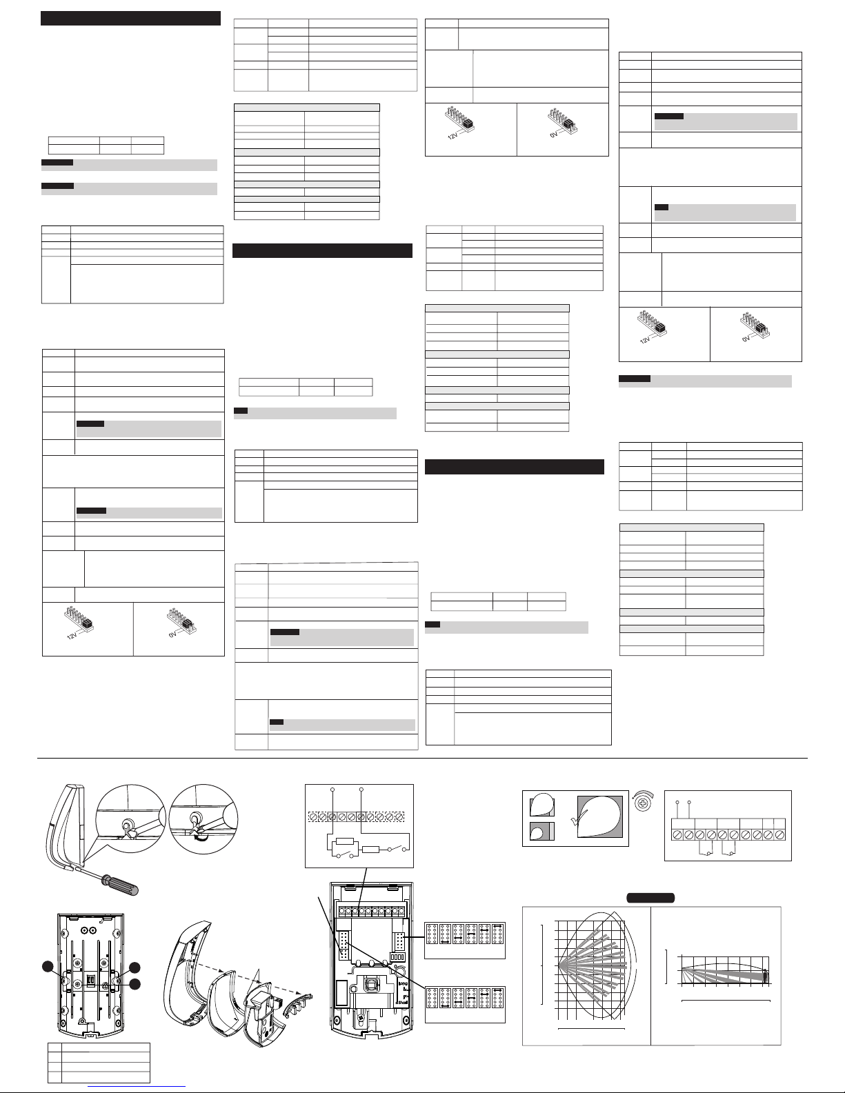
Figure 5.
K-Band MW range adjustment
Figure 6.
Terminal Wiring
12VDC
+ 12 - ALARM
TAMPER LED
Figure 1.
Front cover removal
Figure 3.
Lens Assembly
Short Pin
Lens
Sleeve
Prism
Cover base
Figure 2.
Back cover - Knockouts
Figure 4.
EOL Resistors
A1
A2
A3
Figure 7.
BWare 15m DT GL Coverage
TOP VIEW SIDE VIEW
RK515DTGL
Feet
Meters
30
20
10
0
10
20
30
10
8
6
4
2
0
2
4
6
8
10
02468101214
0 10 20 30 40 50
Feet
15
90°
Feet
10
0
4
2
0
Meters
Feet
0246810121415
0 10 20 30 40 50
J1 - ALARM EOL JUMPERS
1K 2.2K 4.7K 5.6K 6.8KNo
Resistor
(Factory settings)
J2 - TAMPER EOL JUMPERS
J4 - See in Jumper
Settings table
1K 2.2K 4.7K 5.6K 6.8KNo
Resistor
(Factory settings)
PANEL DEOL
+12-
ALARM TAMPER
LED
ALARM
TAMPER
1
2
3A
9
8
8
MIN MAX
Tamper Plate
A1 Right corner mounting knockouts
A2 Wall mounting knockout
A3 Left corner mounting knockout
A
B
 Loading...