

Risco AGM Installation And Programming Instructions

Universal Version
Installation and Programming Instructions

2 AGM - Installation and Programming Instructions

Table of Contents
1. Introduction...............................................................................................4
1.1 Main Features.................................................................................... 4
2. AGM Components....................................................................................5
3. Installation.................................................................................................6
3.1 Preliminary Considerations................................................................ 6
3.2 Installing the AGM............................................................................. 6
3.2.1. SIM Card Installation................................................................. 6
3.2.2. Wall Mounting (Metal Box Installation) ......................................7
4. Wiring the AGM ........................................................................................ 8
4.1 LED Indications ................................................................................. 9
4.2 Automatic GSM Signal Level Measurement...................................... 9
5. AGM Modes of Operation....................................................................... 10
6. Monitoring Station Reporting .................................................................. 10
7. Inputs......................................................................................................11
8. Outputs................................................................................................... 11
8.1 Output Events...................................................................................11
8.2 CLIP Control.....................................................................................12
9. Follow Me Report....................................................................................12
9.1 Follow Me Events.............................................................................12
10. SMS User Remote Control Functions.....................................................13
11. AGM Programming................................................................................. 14
11.1 Installer SMS Programming............................................................14
11.2 SMS Programming Commands......................................................16
12. Technical Specifications .........................................................................22
13. Appendix: Telephone Number Conversion in Line Simulation Mode......23
AGM - Installation and Programming Instructions 3

1. Introduction
RISCO Group’s AGM, Universal Advanced GSM/GPRS Stand alone Module, is a cellular
communication module enabling any existing security panel to communicate through the
GSM cellular network.
The AGM can be used as the main communication line or as a backup to PSTN line
using telephone line simulation.
1.1 Main Features
Full PST N line simulation
Primary or backup GSM/GPRS operation modes
4 alarm inputs
4 outputs that can be activated by system events, SMS or CLIP control
Report to two Monitoring Stations by SMS, GPRS or voice (using line
simulation)
Selective event reporting to 8 Follow Me destinations using SMS, E-mail or
voice messages (using the Plug On voice module)
3 LED Status indication
Advanced remote SMS system control
Local / Remote configuration using the AGM Configuration Software through
the GSM data channel (9600 bps) or by SMS commands
GSM signal supervision and level measurement
Wall and cover tamper protection
Prepaid SIM card support
Backup battery charger and battery protection feature
Quad Band GSM 850/900/1800/1900MHz
Output and Input status verification by SMS commands
4 AGM - Installation and Programming Instructions
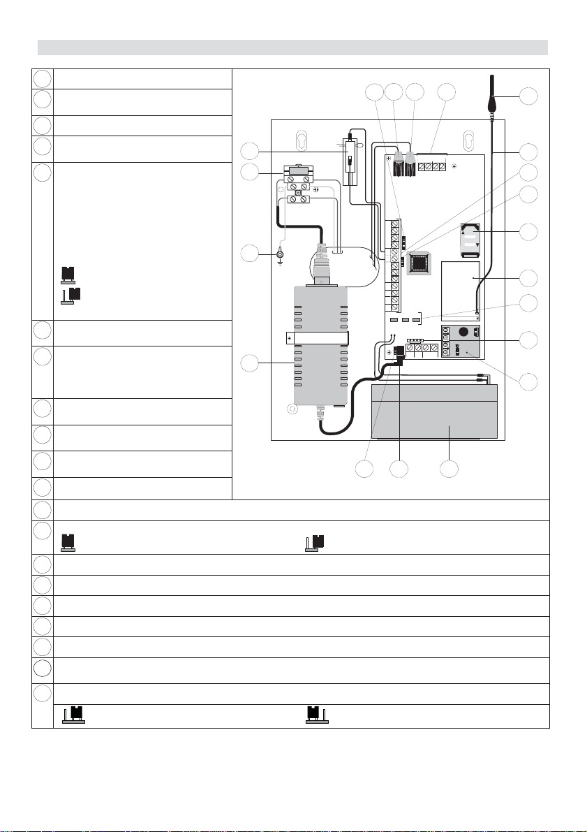
2. AGM Components
1
Tamper Switch (NC)
Mains connectors (fuse
2
protected)
Ground: Box ground connector
3
Power Transformer:
4
(14.5VDC/0.8A)
J14: Battery discharge
5
Protection Circuit Jumper. If AC
power outage occurs, the AGM
automatically disconnects the
1
FUSE: T 0.5A 250V
2
NL
100-240V~50/60 Hz
MAX:0.4 A
battery when the battery voltage
drops below 10.5VDC, in order
to protect the battery from deep
discharge.
3
On - No protection
Off (Default) - Battery
protection is activated
14.5VDC/0.8A Power socket
6
(from Transformer)
Backup Battery:
7
12VDC/1.2A/H
4
Sealed Lead - Acid
Rechargeable Battery
Plug on Voice Module
8
(optional)
J10: PC Connector (via RISCO
9
Group's cable adaptor)
GSM status LEDs: (Power,
10
GSM, Low Battery)
GSM Industrial Module
11
SIM Card Socket
12
J13: Tamper Jumper
13
Tamper is not used (Default) - Tamper is used
Terminal block (See terminal block wiring section on page 8)
14
GSM Antenna Cable
15
GSM Antenna
16
Telephone Line Connection Terminals (in parallel to the phone jack connectors)
17
Telephone Connector - Line: From wall outlet
18
Telephone Connector - Set: To security panel or to premises telephone in absence of control
19
panel.
J15: Used to set Negative (-) or positive (+) remove of inputs 1 - 4 (see page 8).
20
Figure 1. AGM Components
Negative Remove (Default) Positive Remove
19
20
1234 C
COMINPUT TMP
N.C N.O
UØ1 U Ø2 UØ3 UØ4 AUX
LD1 LD3 LD2
L.BA T
GSM
GND
+12 V
J14
1718
PHONE
SET LINE
J15
J13
POWER
BLK
RED
LOCK
PLAY REC
GRN
YEL
BUS
765
16
15
14
13
OPEN
12
11
10
9
8
AGM - Installation and Programming Instructions 5

3. Installation
3.1 Preliminary Considerations
Important:
1. The unit shall be connected to the premises main power, protected by a safety "Double
Pole circuit breaker" which in an electrical fault shall automatically /manually disconnect
power to the unit. Make sure the "Double Pole circuit breaker" is easily accessible.
2. The AGM Module should be installed by a professional installer only.
3. All service and maintenance shall be done only by the installer.
4. The AGM Module does not include any parts that are user replaceable
5. This equipment must be connected to a Protective earthling terminal in the building
installation. Use a min 18AWG yellow/green conductor for this connection.
6. The connection of the earth conductor, and of the 230V wires must be made according to
the local national electrical code and performed by a professional electrician.
Caution: Failing to properly earthen this unit can result in an electric shock.
Ê The AGM Module should be located in a safe and dry place, away from radio and
electromagnetic transmitting devices.
Ê Select a mounting location near a 110/220VAC electrical power supply.
3.2 Installing the AGM
3.2.1. SIM Card Installation
1. Perform steps A to D if a PIN number is required:
Important:
Do not install SIM card while power is applied to the AGM.
Do not touch SIM Card connectors! If doing so, you may release an electrical discharge
that could damage the SIM card.
A. Insert the SIM card into the AGM with PIN code disabled and power up the
AGM.
B. Set the PIN code by means of SMS or AGM Configuration Software.
C. Power down the AGM and remove the SIM card.
D. Place the SIM card in any standard GSM mobile phone (while powered
down).
E. Power up the GSM mobile phone and enable the SIM's required PIN code
(the same PIN code defined in step B).
F. Power down the GSM mobile phone and remove the SIM card.
G. Place the SIM back into the AGM.
2. If required, program the SMS center address into the SIM card using means of
SMS, or AGM Configuration Software.
6 AGM - Installation and Programming Instructions
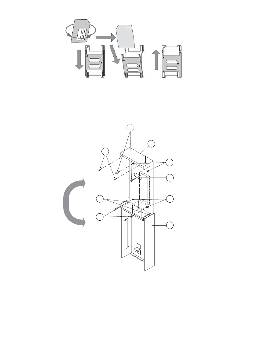
SIM Card
OPEN
LOCK
1. Slide down SIM
card hatch .
2. Open the SIM card
hatch. Inser t SIM card
into dedicated slot.
O
P
E
K
N
C
O
L
Figure 2. SIM Card Insertion
3.2.2. Wall Mounting (Metal Box Installation)
Mounting
Screws
1
Front Cover
Securing Screws
2
Front Cover
Pivots
3
Mounting
Screws
1
Metal Casing
LOCK
3. Close the SIM card
hatch . Slide up to lock.
8
Mounting
Holes
7
Cable Passage
6
Mounting
Holes
5
Front Cover
4
OPEN
Figure 3. AGM– Installation
1. Remove the two screws securing the AGM front cover (2, Figure 3).
2. Tilt and rotate the front cover downwards until it locks vertically to the
casing (alternately lift up to remove the cover).
3. Use the metal casing as a template for marking the installation holes
(mark through the mounting holes, see 5 and 7, Figure 3).
4. Drill the four installation holes in the wall and insert anchors (if
necessary).
AGM - Installation and Programming Instructions 7
5. Insert external cables (GND, Power, and Phone lines) through the cable
passage (6, Figure 3).
6. Align the AGM with the mounting holes and fasten it firmly to the wall with
all four supplied screws (1, Figure 3).
7. Attach the AGM antenna.
8. Connect the AGM backup battery cables to the backup battery.
9. Connect power cables from mains to the power/grounding terminals (2,
Figure 1).
10. Install the front cover in its place (in a reverse sequence of the removal
(see Figure 3).
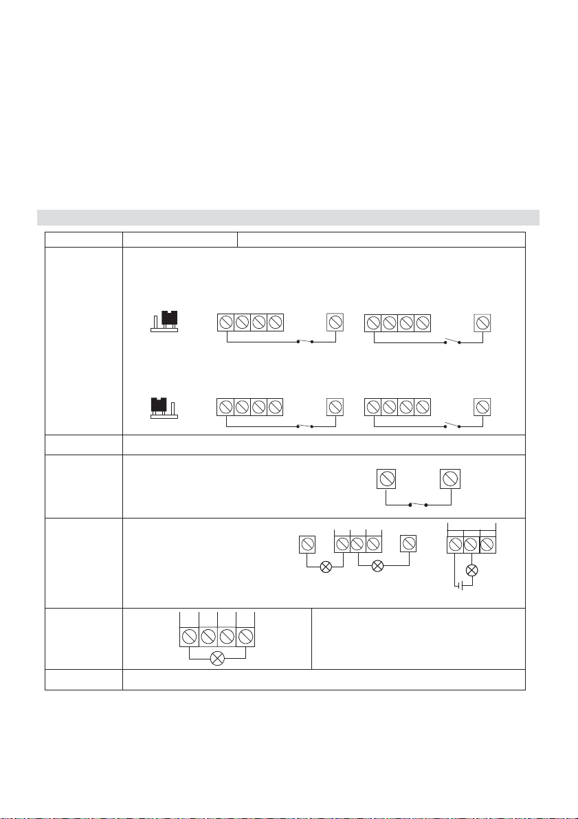
4. Wiring the AGM
Connector Wiring Diagram Description
INPUT
(1, 2, 3, 4)
The Inputs polarity is defined by jumper J15.
Negative remove: Connect the detector/s to the required Input/s
terminal/s (Input 1, 2, 3 or 4) and the COM (0V) terminal.
INPUT
1234
NR (Negative Remove)
(Default)
Positive remove: Connect the detector/s to the required Input/s
terminal/s (Input 1, 2, 3 or 4) and the AUX (14.4VDC) terminal.
INPUT
1234
PR (Positive Remove)
COM 0V
TMP
Tamper alarm activates when
the front cover is open or the
entire box is removed from the
wall.
UO1
Relay (3A)
NC: Normally closed contact
C: Common contact
NO: Normally open contact
UO2 to UO4
(100mA)
UO2 UO3 UO4 AUX
INPUT
1234
INPUT
1234
COM TMP
UO1
COM
NO
NO
NC
N.C C N.O
NC
NC
AUX
COM
AUX
N.C C N.O
External power supply
Wire the devices that you want to
activate to the outputs terminals
COM
AUX
UO1
AUX 14.4VDC
8 AGM - Installation and Programming Instructions
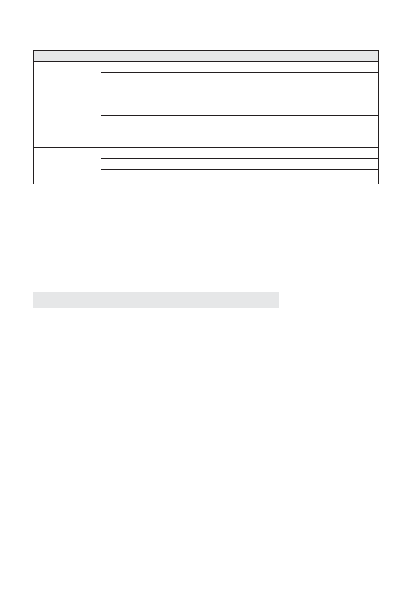
4.1 LED Indications
LED State Description
Power
(Green)
The Power LED indicates the status of power supply to the AGM
On Power OK
Off Power not present
The GSM LED Indicates the GSM network status
GSM
(Yellow)
On Network not available
Flashing GSM communication OK, connected to the network
status
Off Power not present
L.BAT
(Low
Battery, Red)
The Low Battery LED Indicates the GSM backup battery status
On Low Battery (below 11 VDC)
Off Battery OK
4.2 Automatic GSM Signal Level Measurement
After powering up the AGM with the SIM card inside, the module performs an automatic
signal level test.
For the first 30 seconds after powering up, the Green LED will flash between 0-5 times
in cycles, (with a delay of 5 seconds between each cycle), indicating the RSSI level (0=
No network connection, 5= Very High).
If the signal level is not satisfactory or poor, consider installing the AGM in a better
signal receiving location.
GSM Network Signal level Flashes
5 – Very High 5
4 - High 4
3 - Medium 3
2 - Low 2
1 - Very Low 1
0 - No network connection 0
AGM - Installation and Programming Instructions 9
 Loading...