


RISAFoundation
Rapid Interactive Structural Analysis – Foundation Analysis and Design
User’s Guide
26632 Towne Centre Drive, Suite 210
Foothill Ranch, CA 92610
(949) 951-5815
(949) 951-5848 (FAX)
www.risatech.com

Copyright ©2010, RISA TECHNOLOGIES, LLC. All Rights Reserved.
No part of this publication may be reproduced or transmitted in any form or by any means, electronic, or
mechanical, including photocopying, recording, or otherwise, without the prior written permission of
RISA TECHNOLOGIES, LLC.
RISAFoundation is a trademark of RISA TECHNOLOGIES, LLC. RISA, as applied to structural engineering
software, is a trademark of RISA TECHNOLOGIES, LLC.
All other trademarks mentioned in this publication are the property of their respective owners.
Every effort has been made to make this publication as complete and accurate as possible, but no
warranty of fitness is implied. The concepts, methods, and examples presented in this publication are for
illustrative and educational purposes only, and are not intended to be exhaustive or to apply to any
particular engineering problem or design. The advice and strategies contained herein may not be suitable
for your situation. You should consult with a professional where appropriate. RISA TECHNOLOGIES, LLC,
assumes no liability or responsibility to any person or company for direct or indirect damages resulting
from the use of any information contained herein.

Table of Contents
Table of Contents
Introduction .................................................................................................... 1
How to Use this Book .................................................................................................... 1
Using the Online Help ................................................................................................... 3
Technical Support Information ..................................................................................... 4
RISA Technologies Online ............................................................................................. 4
Before You Begin ............................................................................................. 5
RISAFoundation Overview ............................................................................................ 5
Hardware Requirements ............................................................................................... 5
Program Limits .............................................................................................................. 6
License Agreement ....................................................................................................... 7
Installation .................................................................................................................... 8
Maintenance ................................................................................................................. 8
First Look at RISAFoundation ........................................................................... 9
Starting RISAFoundation ............................................................................................... 9
Windows and Dialog Boxes ........................................................................................... 9
Menus and Toolbars ................................................................................................... 11
Managing Windows, Model Views, and Spreadsheets ............................................... 15
Working in Spreadsheets ............................................................................................ 16
Part A: Building a Model from Scratch ........................................................... 17
Part A: Tutorial 1 – Modeling ...................................................................................... 19
Starting a New File ........................................................................................................... 19
Set Global Parameters ...................................................................................................... 20
Drawing Slabs ................................................................................................................... 23
Pedestals .......................................................................................................................... 28
Footings ............................................................................................................................ 30
Grade Beams .................................................................................................................... 32
Soil Regions ...................................................................................................................... 34
Part A: Tutorial 2 – Modifying ..................................................................................... 37
Getting Started ................................................................................................................. 37
Model Manipulation ........................................................................................................ 38
Modifying the Model........................................................................................................ 44
Design Rules ..................................................................................................................... 48
Circular Slabs .................................................................................................................... 49
Part A: Tutorial 3 – Loading ......................................................................................... 53
Getting Started ................................................................................................................. 53
Adding Loads .................................................................................................................... 54
Load Combinations ........................................................................................................... 59
Part A: Tutorial 4 – Solving & Results .......................................................................... 63
Getting Started ................................................................................................................. 63
iii

Table of Contents
Solve the Model ............................................................................................................... 64
Slab Results ...................................................................................................................... 64
Printing ............................................................................................................................. 69
DXF Export ........................................................................................................................ 75
Part B: RISA-3D Integration ........................................................................... 77
Part B: Tutorial 1 – Importing from RISA-3D ............................................................... 79
Opening a RISA-3D File ..................................................................................................... 79
Assign Loads to Load Categories ...................................................................................... 79
Part B: Tutorial 2 – Modeling ...................................................................................... 83
Getting Started ................................................................................................................. 83
Global Parameters ............................................................................................................ 84
Modify the Drawing Grid .................................................................................................. 87
Slabs ................................................................................................................................. 89
Pedestals .......................................................................................................................... 93
Footings ............................................................................................................................ 98
Grade Beams .................................................................................................................. 101
Soil Regions .................................................................................................................... 103
Part B: Tutorial 3 – Modifying ................................................................................... 105
Getting Started ............................................................................................................... 105
Modifying the Model...................................................................................................... 106
Selection Tools ............................................................................................................... 113
Part B: Tutorial 4 – Loading ....................................................................................... 123
Getting Started ............................................................................................................... 123
Apply Loads .................................................................................................................... 125
Part B: Tutorial 5 – Solving & Results ........................................................................ 135
Getting Started ............................................................................................................... 135
Solve the Model ............................................................................................................. 136
Slab Results .................................................................................................................... 137
Printing ........................................................................................................................... 144
DXF Export ...................................................................................................................... 151
Appendix A – RISAFoundation Toolbar Button Quick Reference .................... 153
RISA Toolbar .............................................................................................................. 153
Window Toolbar ....................................................................................................... 155
Drawing Toolbar ........................................................................................................ 158
Selection Toolbar ...................................................................................................... 159
iv

Introduction
Introduction
How to Use this Book
Welcome to the RISAFoundation User’s Guide. If you are a first-time user of RISAFoundation, we
recommend that you start with this book.
Begin by reviewing First Look at RISAFoundation on page 9 to familiarize yourself with the
RISAFoundation menus, toolbars, and shortcuts. There is also a handy reference included as Appendix A
– RISAFoundation Toolbar Button Quick Reference to help you reference toolbar buttons.
Following the introductory sections, notice that the book is divided into two parts: Part A and Part B, as
described below. The two parts are independent, full tutorials, so you may go straight to the part that
best suits your current design needs.
Part A – Building a Model from Scratch will guide you step-by-step through the RISAFoundation modeling
process to build and analyze a model from scratch; Part B – RISA-3D Integration will guide you through
using RISAFoundation as integrated with RISA-3D. In each part, you will create a real-world example of
building and solving a model, making changes, and optimizing the model. Tips and shortcuts will also be
demonstrated along the way.
To complete all the tutorials will take only a few hours. However, you can speed up the process even
further if you skip the supporting text and concentrate only on the action steps, which are indicated with
diamond-shaped bullets, as shown below:
In order for you to achieve accurate results, it is important that you do not miss any of these
action steps while performing the tutorials.
The tutorials build upon themselves from start to finish. You have the option of performing them all at
one time, or performing each one separately. To make this possible, RISA provides model files for you to
load at the beginning of each tutorial. These starter files are located in the RISA folder under Tutorials,
and are named RISAFoundation Tutorial A2 Starter.fnd, RISAFoundation Tutorial A3 Starter.fnd, etc.
After you have completed the tutorials in this guide, you can use the Help Menu and RISAFoundation
General Reference for complete, detailed information on every topic relating to RISAFoundation. The
topics are thoroughly indexed for quick reference.
If you are a more experienced user and are not sure which book will be most helpful for your situation,
consider that the RISAFoundation User’s Guide covers how and when to apply RISAFoundation features
such as slab design strips, but the specifics of how those strips effect the design of your reinforcement
are covered in the Help Menu and the RISAFoundation General Reference.
Where to Download RISAFoundation Book Updates
Every effort has been made to ensure the accuracy of this book at the time of publication. The latest
edition of all books and documents relating to this product are available in Adobe PDF format at
http://www.risatech.com. Click Downloads, Product Documentation, then RISAFoundation.
1

Introduction
This convention:
Indicates:
CAPITAL LETTERS
Names of keys on the keyboard – for example, SHIFT, CTRL, or ALT.
KEY+KEY
One key should be held down and then another key pressed – for example,
CTRL+P or ALT+F4.
Bold text
Boxed text
Bulleted text
User interface options – for example, File menu.
Notes or modeling tip information.
Action item for building the tutorial model.
Tutorial action item for building the model.
Document Conventions
The following conventions are used throughout this book:
2

Introduction
Help on
general topics
On the RISA toolbar, click the Help button . This is the fastest way to get
help on general topics. You can also go to the main menu and click Help,
then select Help Topics.
Once you enter the Help, notice the three tabs on the left: Contents, Index,
and Search. You can explore the Help by topic using either Contents or
Index, or explore the Help using your own specific keywords using Search.
Help on a specific
feature (contextsensitive help)
As you work, notice the Help buttons at the bottom of many of the dialog
boxes. These provide direct access to the Help information related to the
task you are performing.
This context-sensitive help may be accessed by pressing the Help button on
the dialog box or by pressing the F1 key.
Help on toolbar
buttons
Are you uncertain what a toolbar button is for? Simply hold your mouse
pointer over that button (without clicking), and a description of that button
will be displayed.
Using the Online Help
Whether you need help on general topics, specific features, or toolbars, it is all built in to the extensive
RISAFoundation online Help system. The RISAFoundation Help was designed to enable you to pinpoint
the Help information you need quickly, by offering different ways for you to access and locate that Help,
as described below:
3

Introduction
Technical Support Information
Technical support is an integral part of the software packages offered by RISA Technologies, and is
available to all registered licensees at no additional charge for the life of the program. The “life of the
program” is defined as the time period for which that version of the program is the current version or
until the program is discontinued. In other words, whenever a new version of RISAFoundation is released,
the life of the previous version is considered to be ended. Technical support is a limited resource; first
priority will always be given to those clients who are current on their maintenance. For more
information, please see the Maintenance topic on page 8.
RISA Technologies will only support the current version of RISA<Program>. For a list of your support
options, visit our website: www.risatech.com/support.
Before contacting technical support, you may want to take a few minutes to do the following:
Search the Help Menu and all user documentation available for the product.
Search our FAQ database by visiting our website at http://www.risatech.com. Click Support,
then Frequently Asked Questions, and then choose the product.
When you are ready to make a support request, please be prepared to send us your model, and include
the following information:
Your name, company name, and phone number;
Product name and serial number or Key ID;
A detailed problem description; and
Your model (filename.fnd) as an e-mail attachment, or on disc if sending via mail. If your
model contains multiple members, or load combinations, please specify which ones we
should look at.
You can contact Technical Support by e-mail, phone, or by mail, as follows:
E-mail: support@risatech.com
E-mail is usually the best way to communicate with us when sending a model. Please include all the
information listed above.
Phone: (949) 951-5815 or (800) 332-RISA (7472)
Technical support personnel are available from 6:00 A.M. to 5:00 P.M. Pacific Standard Time, Monday
through Friday.
Mail:
If you prefer support via mail, please enclose all information listed above, and mail to:
RISA Technologies, Technical Support
26632 Towne Centre Drive, Suite 210
Foothill Ranch, CA 92610
RISA Technologies Online
Visit RISA Technologies on the Worldwide Web at http://www.risatech.com for:
Answers to frequently asked questions
Downloads of user documentation and tutorials
Software updates – Any known problems are posted on the website, along with possible
work-around procedures and/or service releases to update your software
4

Before You Begin
Before You Begin
RISAFoundation Overview
RISAFoundation has been developed to make the definition, design, and modification of foundation
systems fast and easy. Analysis (including calculation of deflections and stresses) may be performed on
simple foundations or on larger multi-element foundations. Plus, element design optimization is provided
for slabs, footings, and grade beams.
Because of its unique ability to define the model and make revisions both graphically (using the drawing
tools) and numerically (using the customized spreadsheets), RISAFoundation is able to significantly speed
up the design process.
In RISAFoundation, these two methods of entering and editing data work seamlessly together. Everything
designed or drawn graphically is automatically recorded in the spreadsheets (which may be viewed and
edited at any time)—and everything entered in the spreadsheets may be viewed and edited graphically
at any time. The model can be rapidly edited, solved, viewed, modified, re-solved, etc. As you perform
the step-by-step tutorials in this guide, you will be exploring both methods using the drawing tools and
the spreadsheets.
All model editing, model solution and results browsing is accomplished through the same interface, all
within RISAFoundation. This interactive approach offers several unique advantages, such as the ability to
do quick error checking of your model data, the ability to do rapid model editing, solution, editing, and
re-solution without jumping from one program to another.
Hardware Requirements
Minimum
Any Windows compatible computer with a Pentium 3 or better processor
Windows XP/Vista/7
256MB of RAM
200MB of hard disk space
Two or three button mouse
USB port (required for Stand-Alone version or Network Host computer)
Recommended
Windows XP
As much extended RAM as possible
As much free disk space as possible
Two button mouse with wheel
5

Before You Begin
Points
32000
Beams
32000
Plates
32000
Materials
500
Point Loads
2000
Line Loads
2000
Area Loads
200
Load Combinations
1000
Slabs
100
Soil Regions
100
Supports/Footings
1000
Design Strips
100
Note: The amount of space required by RISAFoundation to solve a structural model is dependent on the
size of the model. In general, 500 MB of RAM is adequate to solve most problems, but the more the
better, especially for large models. RISAFoundation will use as much available RAM as possible. If there is
not enough RAM, RISAFoundation will use hard drive space until enough memory is obtained to solve the
problem (causing the solution to run much slower).
Program Limits
Demonstration Version: While you can open and solve a larger model, the largest model that can be
saved to disk with the demonstration version is limited to 10 supports/footings, 5 beams, and 1 soil
region.
6

Before You Begin
License Agreement
END-USER LICENSE AGREEMENT FOR RISA TECHNOLOGIES® SOFTWARE
The RISAFoundation software product (SOFTWARE PRODUCT) includes computer software, the associated media,
any printed materials, and any electronic documentation. By installing, copying or otherwise using the SOFTWARE
PRODUCT, you agree to be bound by the terms of this agreement. If you do not agree with the terms of this
agreement RISA Technologies is unwilling to license the SOFTWARE PRODUCT to you. In such event you must delete
any installations and destroy any copies of the SOFTWARE PRODUCT and return the SOFTWARE PRODUCT to RISA
Technologies within 60 days of purchase for a full refund.
Copyright 2010 by RISA Technologies, LLC. All rights reserved. The SOFTWARE PRODUCT is protected by United
States copyright laws and various international treaties. All rights not specifically granted under this agreement are
reserved by RISA TECHNOLOGIES.
1. SOFTWARE LICENSE. The SOFTWARE PRODUCT is licensed, not sold. All right, title and interest is and remains
vested in RISA TECHNOLOGIES. You may not rent, lease, or lend the SOFTWARE PRODUCT. You are specifically
granted a license to the use of this program on no more than one CPU at any given time. The Network Version of
the SOFTWARE PRODUCT is licensed for simultaneous use on a certain maximum number of network stations that
varies on a per license basis. As part of the license to use the SOFTWARE PRODUCT, the program user acknowledges
the reading, understanding and acceptance of all terms of this agreement. The SOFTWARE PRODUCT may not be
reviewed, compared or evaluated in any manner in any publication without expressed written consent of RISA
Technologies. You may not disassemble, decompile, reverse engineer or modify in any way the SOFTWARE
PRODUCT. If the SOFTWARE PRODUCT was purchased at a discounted price for educational purposes it may in no
event be used for professional design purposes. The terms of this license agreement are binding in perpetuity.
2. DISCLAIMER. We intend that the information contained in the SOFTWARE PRODUCT be accurate and reliable, but
it is entirely the responsibility of the program user to verify the accuracy and applicability of any results obtained
from the SOFTWARE PRODUCT. The SOFTWARE PRODUCT is intended for use by professional engineers and
architects who possess an understanding of structural mechanics. In no event will RISA Technologies or its officers
be liable to anyone for any damages, including any lost profits, lost savings or lost data. In no event will RISA
Technologies or its officers be liable for incidental, special, punitive or consequential damages or professional
malpractice arising out of or in connection with the usage of the SOFTWARE PRODUCT, even if RISA Technologies or
its officers have been advised of or should be aware of the possibility of such damages. RISA TECHNOLOGIES' entire
liability shall be limited to the purchase price of the SOFTWARE PRODUCT.
3. LIMITED WARRANTY. RISA Technologies warrants that the SOFTWARE PRODUCT will operate but does not
warrant that the SOFTWARE PRODUCT will operate error free or without interruption. RISA Technologies sole
obligation and your exclusive remedy under this warranty will be to receive software support from RISA
Technologies via telephone, e-mail or fax. RISA Technologies shall only be obligated to provide support for the most
recent version of the SOFTWARE PRODUCT. If your version of the SOFTWARE PRODUCT is not the most recent
version RISA Technologies shall have no obligation to provide support in any form. Except as stated above the
SOFTWARE PRODUCT is provided without warranty, express or implied, including without limitation the implied
warranties of merchantability and fitness for a particular purpose.
4. PROTECTION DEVICE. In the event the SOFTWARE PRODUCT requires the use of a PROTECTION DEVICE to
operate, you are specifically prohibited from attempting to bypass the functionality of the PROTECTION DEVICE by
any means. If the PROTECTION DEVICE becomes broken or inoperable it should be returned to RISA TECHNOLOGIES
for a replacement. The replacement will not be provided if RISA TECHNOLOGIES can not affirm that the broken
PROTECTION DEVICE was originally provided by RISA TECHNOLOGIES for use with the SOFTWARE PRODUCT. A lost
or stolen PROTECTION DEVICE will not be replaced by RISA TECHNOLOGIES.
5. TERMINATION. RISA TECHNOLOGIES may terminate your right to use the SOFTWARE PRODUCT if you fail to
comply with the terms and conditions of this agreement. In such event you must delete any installations and
destroy any copies of the SOFTWARE PRODUCT and promptly return the SOFTWARE PRODUCT to RISA
Technologies.
7

Before You Begin
6. CHOICE OF LAW. By entering into this Agreement in accordance with Paragraph 1, above, you have agreed to the
exclusive jurisdiction of the State and Federal courts of the State of California, USA for resolution of any dispute you
have relating to the SOFTWARE PRODUCT or related goods and services provided by RISA Technologies. All disputes
therefore shall be resolved in accordance with the laws of the State of California, USA and all parties to this
Agreement expressly agree to exclusive jurisdiction within the State of California, USA. No choice of law rules of any
jurisdiction apply.
"RISA" as applied to structural engineering software is a trademark of RISA Technologies, LLC.
Installation
Installation Instructions
To install RISAFoundation, please follow these instructions:
Place the RISAFoundation CD in your computer CD drive. If the CD starts automatically, skip
the remaining steps, and follow the on-screen instructions.
If the CD does not start after 10 seconds, click the Windows Start button and click Run.
In the Run dialog box, type “d:\launchsetup” (where “d” is the label of your CD drive), and
then click OK.
Follow the on-screen instructions.
RISAFoundation Customization–Important Assumption!
Please ensure that when performing these tutorials, RISAFoundation has not been customized in any
way, and is in the default, installed state. If the installation of RISAFoundation has been customized, you
may reset the program defaults as follows: on the Tools menu, click Reset All Program Defaults.
Maintenance
Program maintenance provides all upgrades to RISAFoundation, discounts on new products, and top
priority for technical support.
When your maintenance expires, you will be given the opportunity to continue program maintenance on
an annual basis. You are under no obligation to continue program maintenance, of course, but if you
decide to discontinue maintenance you will no longer receive RISAFoundation program upgrades and you
will not be eligible for technical support once the version of the program you ended with becomes
obsolete.
8

First Look at RISAFoundation
Title bar
Main menu RISA toolbar
Minimize Maximize Close
Status Bar Starting a Model dialog box Workspace
First Look at RISAFoundation
Starting RISAFoundation
This section describes the RISAFoundation user interface, the toolbars, and shortcuts. We recommend
that you review this section before you begin the tutorials.
Start RISAFoundation as follows:
On the Start button, click All Programs, select RISA, then select RISAFoundation.
Windows and Dialog Boxes
9

First Look at RISAFoundation
Title bar
The title bar at the top of your RISAFoundation window can be very useful. Besides containing
the name of the file that is currently open, it can also be used to move the window and
minimize, maximize, and resize the window.
To move the window, press and hold the title bar with your mouse, then drag to the desired
location.
Minimize,
Maximize,
Close
The three buttons on the right of the title bar control the RISAFoundation window as
follows:
Click Minimize to minimize the window to a button on the taskbar.
Click Maximize to maximize the window to full screen. Once it is full screen, click
Restore Down to restore the window down to its original size.
Click Close to close the window.
Workspace
The actual work that you do in RISAFoundation will be in the main area on the screen, the
workspace. Currently the workspace is empty except for the Starting a New Model dialog box.
As you create new model views and spreadsheets they will also appear in the workspace.
Status bar
The Status bar at the bottom of your screen will report information about your model as you
work.
If the letter “S” is dimmed, a solution has not been performed. After a solution has been
performed, the letter “S” will become blue in color with a red checkmark (as shown below). If
the “S” is yellow, this means you have solution results but there have been modifications via the
Member Redesign dialog box.
To the right of the “S” are 3 status boxes:
The first status box displays general information relative to the task you are
performing.
The second (middle) status box reports the units of the current spreadsheet cell. As
you move from cell to cell, look to the middle status box for the appropriate units.
This box is empty if you are not working in a spreadsheet.
The third status box (on the far right) reports the cursor coordinates as you work in
the model view. This will be demonstrated throughout the tutorial.
Dialog
boxes
Dialog boxes are windows that help you perform a specific function within RISAFoundation. For
example, the Starting a Model dialog box is presented when you first open RISAFoundation,
which helps you find the file you wish to open.
10

First Look at RISAFoundation
File
Provides access to file operations such as opening, saving, and exporting files.
Edit
Provides editing tools that help you modify and manipulate the spreadsheets.
You may use this menu to add or remove information from the spreadsheets or
to sort and mathematically manipulate current spreadsheet data.
Global
Provides access to the Global Parameters dialog box which may be used to
modify global solution and design settings.
Units
Allows you to set units or convert existing units.
View
Allows you to open a new model view or adjust the current model view.
Insert
Used to insert drawing grids, slabs, beams, footings, and loads into the model.
All of these items may be drawn graphically or entered in the spreadsheets.
This menu provides access to the graphical methods that RISAFoundation
provides, while the Spreadsheets menu gives you access to the spreadsheets.
Modify
Allows access to the graphic editing features and may be used to modify
existing model elements.
Spreadsheets
Opens the spreadsheets.
Solve
Solves the model.
Results
Allows access to all analysis result spreadsheets. This button is dimmed when
no results are available, such as before you run a solution.
Tools
Provides tools to help you organize, identify, and correct problems as you
model the structure. Program Preferences are also located here.
Window
Manages all of the windows that you have open in RISAFoundation, whether
they are spreadsheets or model views. Special tiling options are also available
that relate to specific modeling tasks.
Help
Provides access to the RISAFoundation online Help menu. For more
information on Help, see Using the Online Help on page 3.
Menus and Toolbars
Main Menu
The Main menu and its submenus provide access to all features RISAFoundation has to offer, as
summarized below:
11

First Look at RISAFoundation
Window toolbar – any time a
spreadsheet is open, notice
the window toolbar changes
Selection toolbar is not visible in
spreadsheet view
In Spreadsheet View
Window toolbar
(in Model View) – contains
viewing commands
Data Entry toolbar - provides quick
access to spreadsheets (then toolbars
switch to spreadsheet view)
-AND/OR-
Results toolbar - After the model is
solved, the results are displayed here
RISA toolbar – provides access to file operations,
printing, changing design parameters, etc.
Drawing toolbar -
Toggle on with (CTRL+G)
Selection toolbar –
provides tools to help
make selections
Main menu
In Model View
Toolbars
The most commonly used features available on the Main menu are also available on the toolbars as
toolbar buttons. The toolbars are designed to speed up your workflow by placing these tools close to
your workspace and making them easily visible.
Unlike some of the other toolbars, the RISA toolbar never changes.The other toolbars change, depending
on whether you are in model (graphical) view or spreadsheet view.
If you are not sure what a particular toolbar button does, simply position your mouse over the button
and a short definition will display.
Note: You will discover many methods of accessing the tools available in RISAFoundation. The methods
you choose—whether menus, toolbars, or keyboard shortcuts—will simply be a matter of personal
preference.
12
First Look at RISAFoundation
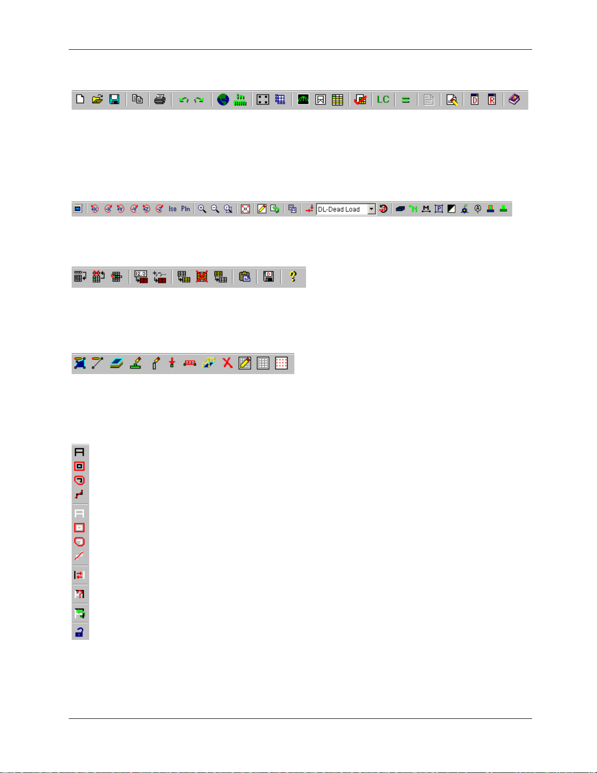
RISA Toolbar
The RISA toolbar is located directly below the Main menu. Unlike some of the other toolbars, the RISA
toolbar never changes. These buttons perform general actions such as opening and closing files, changing
design parameters, printing, and solving the model.
Window Toolbar
…in Model View
The Window toolbar is located directly below the RISA toolbar. When working in a graphic model view,
the buttons provide model viewing tools, such as rotate and zoom, and others.
…in Spreadsheet View
When you are working in a spreadsheet, this toolbar provides spreadsheet editing tools, such as Sort,
Block Fill and Block Math.
Drawing Toolbar
The Drawing toolbar provides tools to assist with creating and modifying your model graphically. This
toolbar may be turned on and off (CTRL+G) as needed.
Selection Toolbar
…only visible in Model View
The Selection toolbar is the vertical toolbar along the left side of the screen.
It provides tools to help you select and unselect parts of the model.
You will need to make selections when you do things like graphically edit a
part of the model or print only part of the results.
13

First Look at RISAFoundation
Spreadsheet Toolbars
(Data Entry and Results Toolbars)
These two toolbars provide access to the spreadsheets. You can
turn them on and off on the RISA toolbar by clicking the Data Entry
button or the Results button .
The Data Entry toolbar is a vertical toolbar on the right of your
screen. It looks different than the other toolbars because its buttons
consist of text instead of images.
The Results toolbar is very similar. It appears after the model has
been solved and provides quick access to the results spreadsheets.
Both toolbars allow you to access the spreadsheets very quickly
while building and solving your model. The buttons appear in the
general order as you may need them.
14
First Look at RISAFoundation
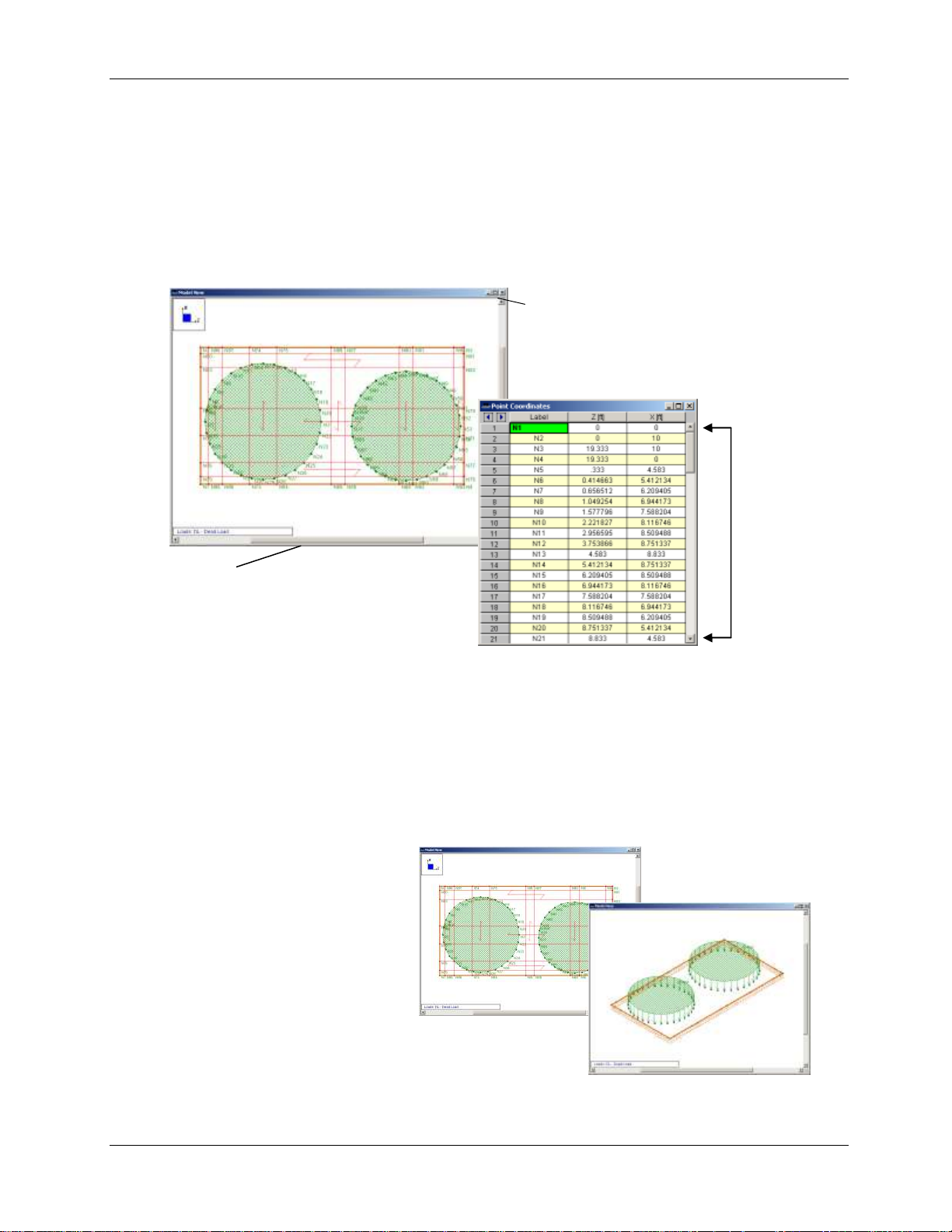
Scroll bar - to view information
outside of the window’s viewing
area, click the scroll arrows or drag
the scroll bar to move the display one
way or the other.
Scroll
arrows &
scroll bar
Minimize,
Maximize, and
Close buttons
Managing Windows, Model Views, and Spreadsheets
Managing Windows
As you work in RISAFoundation, you will be working within model views and spreadsheets, each in their
own window that may be moved around the workspace and resized as you wish. A powerful feature of
RISAFoundation is the ability to have multiple model views and spreadsheets open at one time. The
Window menu provides many options to help manage the display of these windows.
Managing Model Views
You may open as many model view windows as you like. This is especially helpful when working zoomed
in on large models. You might have one overall view and a few views zoomed in and rotated to where
you are currently working. You may have different information plotted in each view.
Remember that the toolbars displayed by RISAFoundation vary depending on which window is active (the
window with a colored title bar is the active window).
For example, if your active window is a
spreadsheet, and you are looking for the
zoom toolbar, you will not be able to
locate it until you click your model,
switching to model view. Then you will be
able to access the zooming tools, and all
the other tools related to modeling.
15

First Look at RISAFoundation
Column label – Click
the column label to
select the entire
column
Scroll bar
Row of cells – Click
the row label (at left)
to select the entire
row
Column of cells
Click any cell. Notice the
status bar displays an
explanation of the current
column.
Working in Spreadsheets
Spreadsheets are comprised of rows and columns of data cells. To add or edit data in a cell, click the cell,
making it the active cell, then type. Only one cell can be active at a time, and it is denoted in green. You
can change which cell is active using the LEFT ARROW, RIGHT ARROW, PAGE UP, PAGE DOWN, HOME
keys, etc.
You may also select blocks of cells to work on. To select a block of cells, click and hold the mouse button
in the first cell in the block, drag to the last cell in the block, then release the mouse. To select an entire
row or column, simply click the row or column label. To select multiple rows or columns, click and drag
the mouse across multiple row or column buttons.
16

Part A: Building a Model from Scratch
Part A: Building a Model from Scratch
This first part of this book (Part A) will focus on building RISAFoundation models from scratch. With the
guidance of the following four tutorials, you will build, solve, and modify a typical industrial foundation
system comprised of several different types of foundations.
The tutorials build upon themselves from start to finish. You have the option of performing them all at
one time, or performing each one separately. To make this possible, RISA provides model files for you to
load at the beginning of each tutorial. These starter files are located in the RISA program folder under
Tutorials, and are named RISAFoundation Tutorial A2 starter.fnd, RISAFoundation Tutorial A3 starter.fnd,
etc.
When you finish all four tutorials, the final product will look like this:
17

Part A: Building a Model from Scratch
To complete all four tutorials will take only a few hours. However, you can speed up the process even
further if you skip the supporting text and concentrate only on the action steps, which are indicated with
diamond-shaped bullets, as shown below:
In order for you to achieve accurate results, it is important that you do not miss any of these
action steps while performing the tutorials.
18

Part A: Tutorial 1 - Modeling
Note: The appearance of your
menus and toolbars may look
slightly different, depending on
your computer screen resolution
and font sizes.
Part A: Tutorial 1 – Modeling
Overview
This first tutorial will introduce the various drawing features that RISAFoundation has to offer. You will
model a project grid, a slab, several footings and grade beams, and explore the Global Parameters of the
model.
Starting a New File
When you are ready to begin, start RISAFoundation if you have not already done so:
Double-click the RISAFoundation icon to start the program. The Starting a Model dialog box will
display, which allows you to create a new model or open an existing file.
You have several startup options, along with a blank drawing grid placed in the workspace. You can
choose to start drawing your model (either by defining beams or slabs, or using a template to generate it
automatically); you can open an existing model; or you can click Close to work on your own.
You will now begin your model by drawing the slabs:
Under Create a New Model, select the Open the Global Parameters window also check box. This
will save you a step by opening the Global Parameters dialog box after you make your starting
selection.
19

Part A: Tutorial 1 - Modeling
Number of Sections
Defines the number of beam force, stress, and deflection results will be reported for
each member.
INTERNAL Sections
Defines the number of places along each beam the software calculates and stores
results (such as deflections and code checks). The beam force diagrams displayed in
the model view and the detail plot are also drawn from these results.
Subgrade Modulus
Defines the global Subgrade Modulus magnitude to apply to the entire model. This
can be overridden with a local soil region with a different Subgrade Modulus if you
require varying soil types in your model.
Mesh Size
Defines the coarseness or fineness of the slab mesh when RISA auto-meshes slabs
during solution.
Tip:
Press TAB to advance to
the next field.
Type any notes you
would like to keep with
the model in the Notes
area.
Global Parameters are
settings that apply to the
entire model.
Select Click here to immediately start drawing slabs.
Because you selected the Open Global Parameters check box option, the Global Parameters dialog box
opens first. This dialog box provides access to global settings that apply to the model as a whole.
Set Global Parameters
Set the Global Parameters as follows:
Type a model title, company name, and your name, as shown below.
Click Apply. The dialog box will remain open.
The Global Parameters dialog box:
Review the Solution settings.
In the Global Parameters dialog box, click the Solution tab. Review the Solution settings, as
summarized below.
20

Part A: Tutorial 1 - Modeling
Allowable Bearing
Defines the global Allowable Bearing Pressure magnitude to apply to the entire
model. This can be overridden with a local soil region with a different Allowable
Bearing Pressure if you require varying soil types in your model.
Max Iterations
Defines the maximum number of iterations RISA will perform during a solution.
Merge Tolerance
Defines the maximum distance two points can be apart and still be merged together.
It is also used when scanning for crossing members and for unattached joints along
the spans of beams.
Solver
Defines which solver will be used.
Save As Defaults
Saves all the modified information in this tab as the default settings for all future
models.
# Shear Regions
Allows you to control the number of regions to be used when
Modify the Solution parameters:
Under Beam Section Options, in the Number of Sections box, type 7 (or you may use the
up/down arrows to increase/decrease the value). In the INTERNAL Sections box, select 100.
In the Mesh Size box, type 36.
Click Apply (the settings will be applied and the dialog box will remain open).
Review the Design settings.
Click the Design tab. Review the Design settings, as summarized below:
21

Part A: Tutorial 1 - Modeling
detailing a beam span.
Region Spacing Incr.
Used to increase or decrease the spacing of shear ties during
design optimization.
Min 1 Bar Dia Spacing
(for Beams Only)
Defines a minimum spacing of one bar diameter between
parallel bars. Otherwise, RISA will default to a two-bar diameter
or one-inch clear spacing (whichever is greater) to allow for lap
splices and continue to maintain adequate spacing between
parallel bars.
Concrete Stress Options
Defines the type of stress block to consider in your analysis.
Concrete Rebar Set
Defines which reinforcement standard set will be used in your
design.
Parme Beta Factor
This value is used to approximate the column’s 3D interaction
surface when using the PCA Load Contour Method.
Code
Defines the concrete design code for your solution.
Modify the Design settings. Because the Parabolic Stress Block is more accurate, select this option:
Under Concrete Stress Options, click Parabolic Stress Block.
Click OK to save your settings and close the Global Parameters dialog box.
22

Part A: Tutorial 1 - Modeling
The Material Set list contains six material types
available as a default in RISAFoundation. If you
would like to use a different material, add it as a
new entry in the Materials spreadsheet (by
adding a new line or row).
Drawing
Drawing Slabs
Now that you have defined the Global Parameters, the Draw Slabs dialog box will display, as shown
below:
For now, use one of the default materials and define a 30 inch, 4 ksi NW slab.
In the Material Set list, click Conc4000NW.
In the Thickness box, type 30.
Click Apply to begin drawing.
Note: Your cursor changes to , indicating that you are now in drawing mode. To exit this mode at any
time, right-click your mouse or press ESC.
Drawing Grid vs. Project Grid
Every time you start a new model, RISAFoundation automatically opens a 30x30 drawing grid. Although
you can use this grid for your model, it is preferable to define a Project Grid. The benefit of using a
Project Grid is that this grid will actually be linked to your model. For example, if you have a row of
footings on a gridline, and decide to move that gridline, the footings move right along with it.
First, toggle off the display of the Drawing Grid:
On the Drawing toolbar, click Drawing Grid to turn off the display of the grid.
Now, draw the Project Grid:
On the Data Entry toolbar, click Project Grid. (If the Data Entry toolbar is not visible on the right
side of your screen, you may need to turn it on. On the RISA toolbar, click the Data Entry toolbar
button to turn it on or off.)
23
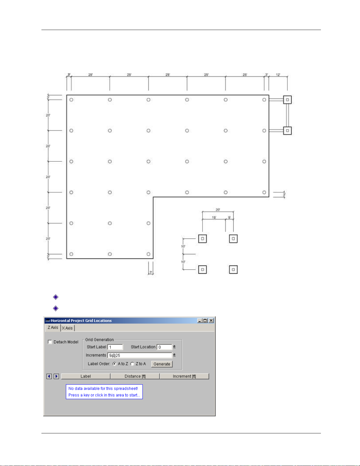
Part A: Tutorial 1 - Modeling
The foundation you will be modeling is shown below. You will use the dimensions from this drawing to
create your Project Grid. Start by generating simple equal increments and then adjust the values in the
spreadsheet to match the exact dimensions.
Define the Grid Locations:
Click the Z Axis tab.
Under Grid Generation, in the Increments box, type 9@25.
24

Part A: Tutorial 1 - Modeling
To view all 10 rows, you may
need to lengthen your
spreadsheet. Click and drag the
right corner of the spreadsheet
in a downward motion.
Tips for Typing Data in Spreadsheets: The
green highlighted cell is the active cell. You
can change the active cell by clicking in a new
cell, or use the TAB key or arrow keys to move
around in the spreadsheet.
You may use the keyboard or the numeric
keypad for typing numbers.
Notice that when you press
ENTER, the values in the
Distance column also
update.
Click Generate.
When you click Generate, nine horizontal project gridlines will be generated on the spreadsheet, each
spaced at 25 feet. Because these are not the exact dimensions, you will need to modify these entries by
manually adjusting the spreadsheet.
Change the Increment value in the spreadsheet section of the dialog box:
In the row labeled 2, in the Increment column, type 3, then press the ENTER key.
Modify a few more values in the Increment column, as follows:
In the row labeled 5, in the Increment column, type 3.
In the row labeled 6, in the Increment column, type 22.
In the row labeled 9, in the Increment column, type 3.
In the row labeled 10, in the Increment column, type 12.
25

Part A: Tutorial 1 - Modeling
The dialog box should now look like this:
To define the X Axis gridlines, you will use a different method to enter the data into this spreadsheet.
You will type all the values at once under the Grid Generation section, in the Increments box (separated
by commas):
Click the X Axis tab.
Under Grid Generation, in the Start Label box, type I (capital i).
In the Increments box, type 3,20,17,3,3@20,3 (including the commas).
In the Label Order area, click Z to A.
Click Generate.
Your spreadsheet should look like this:
Close the spreadsheet:
Click Close to close the spreadsheet.
26

Part A: Tutorial 1 - Modeling
Note: The Project Grid
displays in light blue while a
Drawing Grid would be
displayed in grey.
On the Window toolbar, click Redraw to redraw the grid in the current window.
Your Project Grid will now be displayed in light blue, as shown below:
Notice that you are no longer in drawing mode, and the cursor has returned to (this occurs any time
you open a spreadsheet).
Resume the drawing mode:
Press CTRL+D to recall the Draw Slabs dialog box (no setting changes are necessary, as the
settings you made a few steps earlier for Material Set and Thickness are still present on the
dialog box).
Click Apply to begin drawing the slab.
Use the grid intersections you just created (above) as pick points to draw the slab.
Click the following grid intersections (in this order): A1, A9, F9, F5, I5, I1, then click A1 a second
time to close the polygon.
Note: Once you close the polygon, by clicking the first grid intersection a second time (in this case A1),
the slab will appear.
If you make any mistakes as you draw, use the Undo or Redo buttons to undo or redo your last
step (they are located on the RISA toolbar).
27

Part A: Tutorial 1 - Modeling
Your model should now look like this:
Pedestals
The Pedestal feature in RISAFoundation allows you to draw rectangular or circular pedestals anywhere on
a slab. For your foundation, you will use both types of pedestals. You will start with circular pedestals,
and then later modify a few of those to rectangular (in Tutorial 2).
On the Insert menu, select Pedestals to open the Draw Pedestals dialog box.
In the Draw Pedestals tab, click Circular. In the D (Diameter) box, type 24.
In the Material Set list, click Conc4000NW. In the Height box, type 12.
Click Apply.
28

Part A: Tutorial 1 - Modeling
Note: After you click Apply, your mouse
changes to indicating that you are in
pedestal drawing mode.
Note: It may be helpful to zoom in a bit on your
model. On the Window toolbar, click Zoom In or
use the zooming shortcut by rolling your mouse
wheel in an upward motion.
Rather than click each grid intersection one at a time to place each pedestal, you can use the box select
function of the drawing tool to select a group of grid intersections. Use the “box” method to select all the
grid intersections between B2 and E4 (shown below):
Box the grid intersections between B2 and E4. To do this, click your mouse slightly above and to
the left of grid intersection B2, hold and drag the mouse slightly beyond grid intersection E4, then
release.
Box the grid intersections, as shown. Once you release the mouse, you will see 12 pedestals drawn onto
your slab.
Make two more box selections to complete the pedestal layout:
Box the grid intersections between G2 and H4.
Box the grid intersections between B6 and E8.
29

Part A: Tutorial 1 - Modeling
When finished, your model should look like this:
Footings
Next, you will draw the six footings. Start by defining a footing layout and then apply that layout to the
project grid.
On the Spreadsheets menu, click Footing Definitions.
This opens a spreadsheet that contains all the design parameters for footing design. To create additional
footing designs, simply add as many additional rows to this spreadsheet as you like.
Browse through the various tabs in the spreadsheet to explore the contents. You will use the default
entries so, when finished reviewing, close the spreadsheet.
Browse through the various tabs in this spreadsheet.
Click Close to close the spreadsheet.
Note: If you need help while in a spreadsheet, simply hit the F1 key. The Help will open to a description
of that spreadsheet.
Now that you have defined your footing, you may apply it to your model.
On the Insert menu, click All Support Types. This dialog box allows you to apply typical supports
(Reaction, Spring, etc.), footings, and pile caps.
In the Assign Footing list, click Footing 1 (this is the one you just reviewed in the Footings
spreadsheet). Be sure to select the Use? check box to the right. (Notice that you can also apply a
rotation angle to your footing. But in this case, you will use the default of 0 degrees.)
30

Part A: Tutorial 1 - Modeling
Status bar.
Coordinates of the current
grid intersection location of
the mouse.
Click Apply.
Note: After you click Apply, your mouse changes to indicating that you are now in drawing mode.
In the next few steps, you will be defining six footings for your model. Only two of the six footings fall on
grid intersections (B10 and C10). Begin by drawing those two footings:
Click grid intersections B10 and C10.
Because four of the footings are not on grid intersections, you must use coordinates and snap options to
define their exact location.
On the Drawing toolbar, click Modify Drawing Grid . Click the Snap to Options tab.
Under Universal Snap Increments, make sure that the Z Axis Increments and X Axis Increments
are both set to 1 ft. Select the Use Universal Increments check box.
Click Ok.
As you move your cursor around your model, notice a red star will appear at every 1 ft increment, as
specified above. To see it more clearly, you may need to zoom in on the model by rolling the mouse
wheel forward (away from you).
Also, as you move your mouse, notice the coordinates of the grid intersections are displayed in the lower
right corner of the status bar, as shown below.
31

Part A: Tutorial 1 - Modeling
Assign the final four footings by defining their coordinate locations, as shown below.
Click the following coordinate locations:
(88, 13) (108, 13) (88, -7) (108, -7)
Right-click the mouse or press ESC to exit the drawing mode.
When finished, your model should look like this:
Grade Beams
Note: RISAFoundation treats beams as physical members. This means that the beams will provide fixity
to all joints that occur along the span of the member. Therefore, to be able to later connect the beams to
intermediate elements, it is not necessary to break them into individual members.
To give additional stability to the footings at grid intersections B10 and C10, you will draw some grade
beams. First, turn off the snap points and zoom in on your model so you can view those grid intersections
closer:
On the Drawing toolbar, click Universal Snap Points to turn off the snap points.
On the Window toolbar, click Zoom In (or roll the mouse wheel forward). Use the scroll bars
to reposition the model so that grid points B8 and B10 are in clear view.
32

Part A: Tutorial 1 - Modeling
After drawing a beam, your cursor
remains linked until you either draw
another beam or terminate drawing.
To terminate drawing beams, right-click
the mouse or press ESC.
To exit the drawing mode completely,
right-click the mouse or press ESC a
second time.
Next, you will define the material to be used for the beams:
On the Insert menu, click Beams.
In the Material Set list, select Conc4000NW. In the Depth(D) box, type 24. In the Width(W) box,
type 18.
Click Apply.
Now, draw the first beam:
Click grid intersections B8 and B10. Notice that your cursor remains linked to the node at B10,
allowing you to continue drawing a second beam without interruption (which you will do in the
next step).
Continue drawing the remaining beams:
Click grid intersection C10 to create the second beam; and finally C8 to create the third beam.
33

Part A: Tutorial 1 - Modeling
Now that you are finished drawing your beams, right-click the mouse or press ESC two times to
terminate drawing and exit the drawing mode.
Now that you have completed drawing your foundation elements, render the view:
On the Window toolbar, click Redraw to resize the model within the window.
On the Window toolbar, click Rendering to view your model with a color fill.
Soil Regions
Soil regions may be applied to your model in individual areas if you want them to vary from the default
soil properties you entered in Global Parameters. For your model, you will use both options to apply
different soil regions under different parts of your model. Start by setting a global Subgrade Modulus.
On the RISA toolbar, click Set Global Parameters to re-open the Global Parameters dialog
box.
Click the Solution tab.
In the Subgrade Modulus box, type 120.
34

Part A: Tutorial 1 - Modeling
Execute the changes and close the dialog box:
Click OK.
Now, this will be the default subgrade modulus for the model and it will be used to establish the elastic
stiffness of the soil for the entire model. Because you want to establish an area with a different Subgrade
Modulus and Allowable Bearing Pressure, you will do so with the Draw Soil Regions tool.
On the Insert menu, select Soil Regions.
In the Allowable Bearing Pressure box, type 2.
Click Apply to begin drawing the region.
To draw the soil region over the four footings you created earlier (at the bottom of the model), you will
need to turn Universal Snaps back on and draw your soil region as follows:
On the Drawing toolbar, click Universal Snap Points to turn on the snap points.
35

Part A: Tutorial 1 - Modeling
Click grid intersections G6, G8, then coordinates (128, -16), (78, -16), and finally click grid
intersection G6 a second time to close the polygon.
Note: If you had drawn your soil region under just a portion of a footing, the footing would be designed
for the soil type under the defining footing joint. They will not be designed for half one soil region, half
another.
This completes your initial foundation design. You may now change to rendered, isometric view and
review your model for accuracy:
On the Window toolbar, click Isometric to view the model in isometric view.
On the Window toolbar, click Rendering once more to view the full rendered view.
This is the end of Tutorial A1.
You can save your model to be used as the starting point for the next tutorial, or begin the next tutorial
using the .fnd starter file in the RISAFoundation Tutorials folder. To save the model:
Select Save As from the File menu. Enter in a file name and click Save.
36

Part A: Tutorial 2 - Modifying
Part A: Tutorial 2 – Modifying
Overview
Now that you have laid out your RISAFoundation model, it is inevitable that modifications or changes will
need to be made. One of the most powerful features of RISA software is the ability to quickly and
effectively make changes to an existing model without having to recreate the model—this tutorial will
demonstrate how.
Getting Started
This tutorial continues where the previous tutorial ended, so follow these steps to get your model up and
running:
If you are continuing from the previous tutorial:
On the Main menu, select Single View from the Window menu.
Skip ahead to the next section titled Model Manipulation.
-OR- If you are starting here from scratch, follow the steps below to load the starter file provided by RISA
Technologies:
Double-click the RISAFoundation icon to start the program.
Click Open File from the Starting a Model dialog box.
Double-click the Tutorials folder, select Tutorial A2 Starter.fnd and click Open.
Click Close (or Cancel) to exit the Global Parameters dialog box.
On the Window toolbar, click the Graphic Editing Toolbar button to activate the Drawing
toolbar.
Your model should now look like this:
37
Part A: Tutorial 2 - Modifying
The first part of this tutorial will guide you through some of the basic graphical functions of
RISAFoundation. As you build larger, more complex models, the view manipulation features (such as
zooming, panning, and rotating) will help you ensure model building precision during every step of the
process.
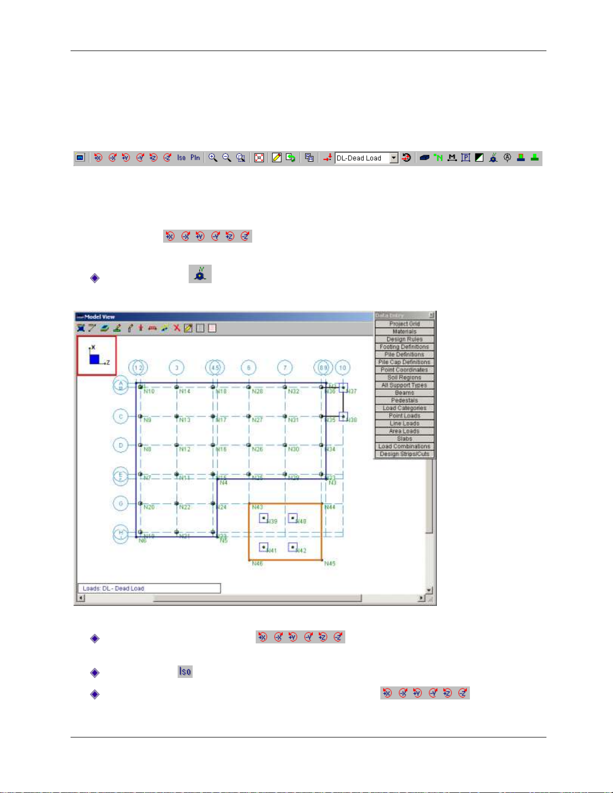
The Window toolbar provides these view manipulation features:
Model Manipulation
Rotating
The Rotate buttons are used to rotate the model in respect to the global axes of the
model. Display the global axes icon so that you can see how the model rotates in reference to these axes.
Click Global Axes to display the global axes icon.
The global axes icon will appear in the upper left hand corner of your model view.
Experiment using some of these view manipulation buttons:
Click each of the Rotate buttons a few times. Watch the global axes icon to
see the effect of each.
Click Isometric to snap the model into isometric view.
Now that you are in isometric view, click the Rotate buttons once again to
see how the model rotates in 3D.
38

Part A: Tutorial 2 - Modifying
When you are finished, click the Isometric button once more to bring your model back into
isometric view.
Your model should now look like this in isometric view:
Zooming
The Zoom buttons are also located on the Window toolbar, just to the right of the Rotate
buttons. These are used to zoom in or zoom out of your model.
Try clicking on these buttons to experiment with them.
The last zoom button, the Box Zoom button allows you to use your cursor to draw a box around the
area you would like to zoom in on. Try this by adjusting your model view, then zoom in on the four
footings in the lower portion of the model:
On the Window toolbar, click Redraw to redraw the model in full model view. Then, click
Planar to snap back to a XZ planar view.
On the RISA toolbar, click the Data Entry toolbar button to close the Data Entry toolbar (or
click Close on the Data Entry toolbar itself).
On the Window toolbar, click Box Zoom and then draw a box around the lower four footings
by clicking and dragging your mouse. When you release the mouse, the boxed area will zoom in
to the full size of the window.
39
Part A: Tutorial 2 - Modifying
You may also zoom in and out using
the wheel button on your mouse.
Roll the wheel forward to zoom in,
and back (towards you) to zoom out.
If your mouse has a wheel, you will also be able to zoom using the mouse wheel:
Roll the mouse wheel forward and backward a few times to see the zooming effect.
On the Window toolbar, click Redraw to redraw the model within your window.
Panning
With the mouse wheel, you will also be able to use RISAFoundation’s panning feature:
Simply press down the mouse wheel anywhere on your model, then hold and drag to the desired
location. This will drag your model to the new location.
When you are finished, return to your original, full model view:
On the Window toolbar, click Planar , then Redraw .
Your window should now look like this:
40

Part A: Tutorial 2 - Modifying
New Model View - opens a new window
containing the current model view (but does not
include any rendering or view modifications).
Clone View - opens a new window containing the
current model view (including any rendering or
viewing changes you have made).
Example 1. Notice the current model view is
in XY view and rendered--the cloned view is
identical.
Example 2. Even though the original model
view is rendered and in XY view, the New
Model View opens in wireframe, isometric
view (the RISAFoundation default view).
Multiple Views
RISAFoundation provides the ability to display multiple views of your model using two powerful tools:
Clone View and New Model View . These tools allow you to keep your original model view
(window) intact in one view, then create additional views to display different views of the model.
Listed below are some scenarios in which you may want to use these tools:
To isolate specific parts of your model to see how those parts are affected by your modifications.
If you do not want to change your existing view, but need to view a different side of the model,
simply open a new window to view the other side.
When viewing results, you can plot different results information in each view.
Note: Each view, whether created with Clone View or New Model View, is independent and can be
rotated, rendered, zoomed, selected, etc., without affecting the other model views. However, any
modeling changes you make in any view will be automatically updated in the other views.
You will now explore this feature a bit. Before you create a new model view, turn the joint labels off, so
you will be able to visually see the difference between this view and the newly created view:
On the Window toolbar, click Joint Labels to turn off the joint labels.
Now, create a new model view:
On the RISA toolbar, click New Model View .
41

Part A: Tutorial 2 - Modifying
The new model view is
now the active view.
To move back and forth
between the views, click
in the windows. Or, on
the Window menu,
select the view you
want to make active.
Compare the two model views you now have open. On the newly created model view, notice the node
labels are turned on (even though you turned the node labels off on the original window; remember
viewing changes are not reflected when using the New Model View tool).
Render your new model view, then compare again:
Place your cursor in the newly created model view to make sure it is the active window.
On the Window toolbar, click Rendering two times to render the new model view. Notice the
original view remains unchanged.
Next, you will modify the model a bit so you can see the effect on each view:
Make sure your newly created model view is the active window.
Press CTRL+G to open the Drawing toolbar.
On the Drawing toolbar, click Delete .
42

Part A: Tutorial 2 - Modifying
The Delete Items dialog box will display:
Specify the four footings you want to delete, then compare the views:
Click Delete LOADS/ITEMS by Clicking Individually, then click Apply.
Click to delete the four footings at the base of the model.
Click the title bar and drag the window to the right so you can see both model views.
Notice that the four footings have also been deleted from the other model view.
Since you actually want to keep these footings in your model, undo the last four deletions:
On the RISA toolbar, click Undo four times to return the footings back to the model.
On the Window menu, select Single View to return to the original, full size model view.
43

Part A: Tutorial 2 - Modifying
Your model should now look like this:
Modifying the Model
Selection Tools
In this section, you will explore how to combine the viewing options you just learned about with the
selection tools to make those inevitable model design changes in RISAFoundation.
Next, you will modify your model to look like this:
44

Part A: Tutorial 2 - Modifying
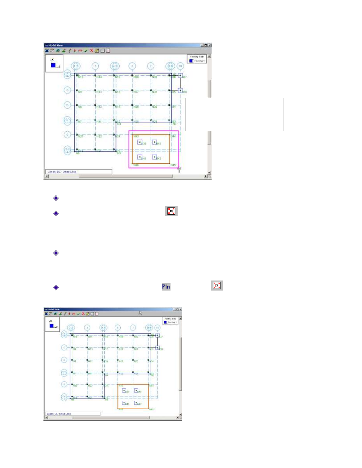
The entire model is currently selected, so start by unselecting the entire model, then select only the parts
you want modified (in this case, the pedestals in the front, lower region of your slab):
On the Selection toolbar, click Unselect All (the Selection toolbar is located on the left side
of your screen).
Note: When you unselect elements, they will display in grey. Any modifications you make to the model
will only apply to “selected” elements. Therefore, selecting and/or unselecting elements enables you to
isolate various portions of your model. For example, any elements that are selected will be modified; any
elements that are unselected will be excluded.
Next, you will use the Criteria Selection tool to select the pedestals (and exclude all the other
elements).
On the Selection toolbar, click Criteria Selection . Click the Pedestals tab.
Under Pedestal Properties, in the Shape list, click CRND24.
Under Selection Options, click Select Pedestals?
Next, define the X and Z coordinates:
Click the Coordinates tab.
Under Coordinate Bounds, enter these values:
In the X Coordinate row, in the Maximum column, type 23 (leave the Minimum column blank).
In the Z Coordinate row, in the Minimum column, type 3. In the Maximum column, type 53.
Pay close attention to the selection options near the bottom of the dialog box:
Under Selection Options, click Select Items?
Select the Include Criteria On Other Pages? check box (if it is not already selected).
Click OK.
45

Part A: Tutorial 2 - Modifying
Only the lower six pedestals will be selected, as shown below.
Now that you have selected the pedestals to be modified, use the modify tool to quickly update your
model.
On the Modify menu, select Pedestals.
In the Pedestal Shape and Dimensions area, select the Use? check box. Then, click Rectangular.
In the D (diameter) box, type 30. In the W (width) box, type 24.
Under What happens when Apply is pressed? select Apply Entries to All Selected Pedestals.
The dialog box should look like this:
Once you verify the entries are correct:
Click Apply.
46

Part A: Tutorial 2 - Modifying
Notice that all selected pedestals have become rectangular. Select the remaining pedestals so you can
compare the two pedestal types:
On the Selection toolbar, click Criteria Selection . Click the Pedestals tab.
Under Pedestal Properties, in the Shape list, select CRND24.
Click OK.
Now, all your slab pedestals are selected as shown below:
Before you re-select the entire model, save this selected state so that you may access it for later
modeling and/or modifications:
On the View menu, select Save or Recall Selection States.
Click Save. A dialog box will appear asking for a description name.
Type: Slab Pedestals.
Click Ok. Then click Close.
Now you have saved this selection state and may retrieve it any time by coming back to this tool (on the
View menu, select Save or Recall Selection States, then clicking the Retrieve button).
Return to your model view and select the entire model.
Place your cursor anywhere in the model view, and right-click your mouse. A shortcut menu will
appear, click Select, then click All.
47

Part A: Tutorial 2 - Modifying
The shortcut menu appears:
Now the entire model will be selected again, as shown in the image below:
Design Rules
The Design Rules spreadsheet allows you to define or change the parameters for your solution, as you
will do next:
Verify that the Data Entry toolbar is visible on the right side of your workspace. If not, on the
RISA toolbar, click the Data Entry toolbar button .This toolbar provides quick access to the
spreadsheets.
On the Data Entry toolbar, click Design Rules to open the Design Rules spreadsheet.
48

Part A: Tutorial 2 - Modifying
Review the General and Beam parameters:
Click the General and Beam tabs to scan through the available options. There is no need to
change any of the default parameters for these two tabs.
Modify the Slab parameters:
Click the Slab tab. Modify the parameters so that your spreadsheet matches the image below.
Modify the Footing parameters:
Click the Footing/Pile Cap tab. Modify the parameters so that your spreadsheet matches the
image below.
Modify the Pedestal parameters:
Click the Pedestal tab. Modify the parameters so that your spreadsheet matches the image
below.
When finished, close the spreadsheet:
Click Close .
Circular Slabs
Now that all the existing elements have been modified, add the circular slab in the lower right hand
corner using the Circular Slab Generator:
Note: This generator can be a very useful tool. Besides generating the slab, it will also add loads to the
slab, and add the design strips within the slab. Loads and design strips will be explained in more detail in
later tutorials.
49

Part A: Tutorial 2 - Modifying
On the Insert menu, select Circular Foundation This will open the Circular Slab Generator dialog
box.
Complete the dialog box so that it matches the image below.
When finished, apply the changes and close the dialog box:
Click OK.
Notice the slab is now drawn on your model.
50

Part A: Tutorial 2 - Modifying
Zooming shortcut: Zoom in by
rolling the mouse wheel forward.
Panning: To move the model
around in the window, press the
mouse wheel down, hold and drag
in any direction.
Notice that the circular slab overlaps the soil region you drew earlier. So, next, you will modify the soil
region to extend completely under the new slab. The best way to do this is to simply change the
coordinates of the four nodes that define the corners of the soil region.
First, zoom in for better viewing of this region:
Zoom in on the lower right corner of your model using zooming and panning techniques.
Zoom in on this region of your model:
Get information on the node that defines the upper right corner of the soil region:
Double click the upper right corner node (N44) of the soil region.
This opens the Information dialog box for that point.
Change the coordinates to extend beneath the new slab:
Under Coordinates, in the Z Coordinate box, type 165. In the X Coordinate box, type 40.
Click OK.
51

Part A: Tutorial 2 - Modifying
Now, extend the node that defines the lower right corner of the soil region:
Double click the node N45.
Under Coordinates, in the Z Coordinate box, type 165. In the X Coordinate box, type -35.
Click OK.
Click Redraw to view the entire model again.
Your soil region has now expanded beyond and lies beneath the new circular slab. You can also view your
model in isometric, rendered view.
Click Iso to place the model into isometric view.
Click Rendering twice to place the model into a full rendered view.
This is the end of Tutorial A2.
You can save your model to be used as the starting point for the next tutorial, or begin the next tutorial
using the .fnd starter file in the RISAFoundation Tutorials folder. To save the model:
Select Save As from the File menu. Enter in a file name and click Save.
52

Part A: Tutorial 3 - Loading
Part A: Tutorial 3 – Loading
Overview
With the model layout complete, you can now explore the many ways to apply loading in
RISAFoundation. In the previous tutorial, you applied both a line load and an area load to your circular
slab with the circular slab load generator. In this tutorial, you will be expanding on this by adding some
additional line loads and point loads.
You will find that whenever you define a load in RISAFoundation, you will also immediately assign it to a
load category. The load categories are then used to combine the loads into load combinations (along with
multiplier factors) for solution.
Getting Started
This tutorial continues where the previous tutorial ended, so follow these steps to get your model up and
running:
If you are continuing from the previous tutorial:
On the Main menu, select Single View from the Window menu.
Skip ahead to the next section titled Adding Loads.
-OR- If you are starting here from scratch, follow the steps below to load the starter file provided by RISA
Technologies:
Double-click the RISAFoundation icon to start the program.
Click Open File from the Starting a Model dialog box.
Double-click the Tutorials folder, select Tutorial A3 Starter.fnd and click Open.
Click Close (or Cancel) to exit the Global Parameters dialog box.
On the Window toolbar, click the Graphic Editing Toolbar button to activate the Drawing
toolbar.
Your model should look like this:
53

Part A: Tutorial 3 - Loading
Adding Loads
Line Loads
Line loads in RISAFoundation are all applied with positive magnitude signifying a downward force. You
can use line loads to model the equipment bearing on the foundation.
On the Drawing toolbar, click Draw Line Loads .
In the Load Category Code list, click LL-Live Load. Then, in the Start Magnitude box (and the End
Magnitude box), type 20.
Click Apply.
To ensure accurate grid selections, turn on the snap points and zoom in on your model view:
On the Drawing toolbar, click Universal Snap Points . When selected, the button will appear
pressed in .
On the Window toolbar, click Zoom In a few times (or roll the mouse wheel forward). This
will enlarge your model making it easier to view.
Note: Once you zoom in, you may need to move your model around on the screen to reposition the
model. Use the panning technique described earlier (press the mouse wheel down, hold, then drag the
model view in any direction).
54

Part A: Tutorial 3 - Loading
Now, make your grid selections by defining their coordinate locations, as shown below.
Click the coordinate location (3, 75), then (53,75). Right click (or press ESC) to release the mouse.
Click the coordinate location (3, 71), then (53,71). Right click (or press ESC) two times to release
the mouse and exit the drawing mode.
Now that you have made your grid selections, zoom back out to full model view.
On the Window toolbar, click Redraw .
When you are finished, your model should like this:
Point Loads
Point load direction is the same as for line loads; a positive force signifies a downward force. You can use
these to model loads to the pedestals, or apply them anywhere on the slab.
Start by applying load to the slab pedestals. You can do this easily by unselecting the entire model, then
retrieving your Slab Pedestals selection state from the previous tutorial:
On the Selection toolbar, click Unselect All .
Also on the Selection toolbar, click Save/Recall Selection . Make sure that Slab Pedestals is
selected, and click Retrieve.
Now that your pedestals are selected, you are ready to apply load.
On the Drawing toolbar, click Draw Point Loads .
In the Load Category Code list, click DL-Dead Load. In the Magnitude box, type 20.
Under What happens when Apply is pressed?, click Apply Load to All Selected Points.
55

Part A: Tutorial 3 - Loading
Verify the dialog box settings, then apply:
Click Apply.
Notice the loads have been added, and your model should now look like this:
Next, apply the live loads:
On the Drawing toolbar, click Draw Point Loads (or press CTRL+D to recall the last dialog
box).
In the Load Category Code list, select LL-Live Load. In the Magnitude box, type 15.
Under What happens when Apply is pressed?, click Apply Load to All Selected Points.
56

Part A: Tutorial 3 - Loading
Note: As soon as you apply this load, notice
the Window toolbar loads display button
switches to display only the LL-Live Load
category loads (this will be
explained in more detail later in this tutorial).
Verify the dialog box settings, then apply:
Click Apply.
Lastly, apply loading to your footings.
On the Selection toolbar, click Unselect All to unselect the entire model.
Also on the Selection toolbar, click Criteria Selection . Click the Supports/Beams tab.
In the Point Selection Criteria area, select the Use? check box. Under Point Properties, in the
Footing list, click Footing 1.
57
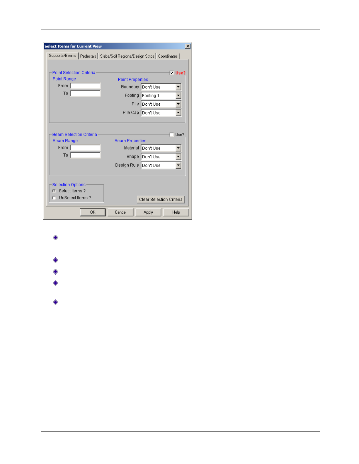
Part A: Tutorial 3 - Loading
Verify the dialog box settings, then apply:
Click OK.
Continue adding loads, but this time use the Insert menu to access the Point Loads dialog box:
On the Insert menu, click Loads, then click Point Load.
In the Load Category Code list, click DL-Dead Load. In the Magnitude box, type 15.
Under What happens when Apply is pressed?, click Apply Load to All Selected Points. Also,
select the Keep this dialog open check box.
Click Apply.
58

Part A: Tutorial 3 - Loading
Verify that the load was properly applied on your footings. (If you need to move the Draw Point Loads
dialog box, click the title bar and hold, then drag the dialog box to the new location.)
Finish adding your loads:
In the Load Category Code list, click LL-Live Load. In the Magnitude box, type 10.
Click Apply.
Then, click Close to close the dialog box.
Now that you have finished applying your loads, you can verify their accuracy by viewing them in the
spreadsheets.
On the Spreadsheets menu, click Load Categories.
This spreadsheet displays the total number of each type of load you have applied to each load category.
This may be used as a quick check to make sure your loads are assigned to the appropriate categories.
Close the spreadsheet and return to the model view:
Click Close .
Load Combinations
Now that you have applied all your loads, you can combine them with multiplying factors to create load
combinations. RISAFoundation offers two ways to do this: you can either enter your load combinations
manually into the spreadsheets, or use the Load Combination Generator to generate your load
combinations automatically.
For this tutorial, you will generate your load combinations automatically using the Load Combination
Generator:
On the Spreadsheets menu, click Load Combinations.
The Load Combination spreadsheet will display:
This spreadsheet contains two default load combinations. To accurately generate all the appropriate
combinations per the design code, you must first delete any load combinations currently in the
spreadsheet:
On the Window toolbar, click Delete Line two times to delete both rows (or use the shortcut
by pressing the F4 key two times).
Now, generate the load combinations:
On the Window toolbar, click LC Generator .
59

Part A: Tutorial 3 - Loading
In the Load Combination Region list, click United States. In the Load Combination Code list, click
ACI 2005 Strength.
Under Wind Load Options, click None.
Under Seismic Load Options, click None.
Note: These are specified as none because you have not applied any loads in these categories.
Verify the dialog box settings, then generate:
Click Generate.
The spreadsheet contains 7 load combinations and looks like this (you may need to resize the
spreadsheet to view them all):
Generate additional load combinations, this time specifying a different code:
On the Window toolbar, click LC Generator again.
In the Load Combination Code list, click IBC 2006 ASD.
Click Generate.
60

Part A: Tutorial 3 - Loading
Display Loads –
Toggles display of
the loads on or off.
Loads List – Lists the
available loads.
Switch Loads – Switch loads display
between load categories or load
combinations.
The new load combinations will be appended to the 7 previously generated. Now, your Load
Combinations spreadsheet contains 15 combinations, as shown below.
Close the spreadsheet and return to the model view:
Click Close .
Loads Display
Until this point, you have been able to view your loads graphically, but you have only seen them
displayed by load category. RISAFoundation also allows you to view your loads by load combination. This
option allows you to view your loads, as magnified or reduced per your multiplying factors.
The Loads Display buttons help view the load categories and load combinations, as shown below:
Experiment by “switching” to display load combinations (instead of categories):
On the Window toolbar, click Switch Loads . Notice that the Loads List will now change to
display the 15 load combinations you generated earlier.
Now, display one of the load combinations:
On the Selection toolbar, click Select All .
On the Window toolbar, in the Loads List, click LC 13: IBC 16-11(a).
61

Part A: Tutorial 3 – Loading
Your model view will show the displayed loads, as multiplied by the load combination factors in the
model view.
This is the end of Tutorial A3.
You can save your model to be used as the starting point for the next tutorial, or begin the next tutorial
using the .fnd starter file in the RISAFoundation Tutorials folder. To save the model:
Select Save As from the File menu. Enter in a file name and click Save.
62

Part A: Tutorial 4 – Solving & Results
Part A: Tutorial 4 – Solving & Results
Overview
The last step in the modeling process is to solve the model and review the results. RISAFoundation
presents results in several ways. You may view the data in the spreadsheets, view a member detail
report, or view the results graphically.
Getting Started
This tutorial continues where the previous tutorial ended, so follow these steps to get your model up and
running:
If you are continuing from the previous tutorial:
On the Main menu, select Single View from the Window menu.
Skip ahead to the next section titled Solve the Model.
-OR- If you are starting here from scratch, follow the steps below to load the starter file provided by RISA
Technologies:
Double-click the RISAFoundation icon to start the program.
Click Open File from the Starting a Model dialog box.
Double-click the Tutorials folder, select Tutorial A4 Starter.fnd and click Open.
Click Close (or Cancel) to exit the Global Parameters dialog box.
On the Window toolbar, click the Graphic Editing Toolbar button to activate the Drawing
toolbar.
Your screen should now look like this:
63

Part A: Tutorial 4 – Solving & Results
The Results toolbar
contains links to each
of the results
spreadsheets.
The Warning Log spreadsheet
reports the various warnings
related to your solution.
Solve the Model
Start by solving the model.
On the RISA toolbar, click Solve .
When the solution is complete, two new items will display: the Results toolbar and the Warning Log
spreadsheet:
The two warnings associated with this model are in reference to a limitation in the pedestal design.
These can be ignored because, while they limit the design checks performed by the program, they do not
cause erroneous results in the design checks that were completed.
Click Close to close the Warning Log spreadsheet.
Slab Results
When your model is solved, slab elements are automatically submeshed into plate elements. Therefore,
RISAFoundation displays two plate result spreadsheets: Plate Forces and Plate Corner Forces. Review the
data in both spreadsheets to get specific force data for each submeshed plate:
On the Results toolbar, click Plate Forces.
On the Results toolbar, click Plate Corner Forces.
Notice that both spreadsheets are organized by Load Combination and then by Plate Label. To view the
results by Plate Label and then Load Combination, change your Preferences settings:
On the Tools menu, click Preferences. Click the Solution and Results tab.
Click Batch results displayed by ITEM.
64

Part A: Tutorial 4 – Solving & Results
If this parameter is selected, the
spreadsheet will list the results by ITEM.
All other spreadsheets will reflect the
change (it is not necessary to perform
another solution).
Verify the settings, then accept the changes:
Click OK.
Briefly review several of the other results spreadsheets.
On the Results menu, click Point Reactions.
On the Results menu, click Point Deflections.
When you are finished reviewing the spreadsheets, close the spreadsheets and return to the original
model view:
On the Window menu, click Single View.
Design Strips
Design strips are used to create design regions within a slab. Each design strip will contain automatically
defined design cuts which will control the reinforcement design for that design strip. The results for the
entire design strip will be determined by the maximum moment demand of the governing design cut
within that design strip. Because one governing design cut controls the entire design strip, it is critical
that good engineering judgment is used to determine an appropriate width for the design strip.
You will draw design strips under your two line loads, as this is the most likely place for maximum
moment. Because the design strip designs reinforcement in only one direction, you must add at least two
strips: one in each direction.
Start by turning off the loads and point labels:
From the View menu, click Loads.
From the View menu, click Point Labels.
Now draw your Design Strip.
On the Selection toolbar, click Design Strip .
65

Part A: Tutorial 4 – Solving & Results
First, draw the strip to design the horizontal (Z axis direction) reinforcement:
Under Rebar Orientation, click Plan Horizontal.
In the Design Cuts Per Strip box, type 50.
Verify the settings, then accept the changes:
Click Apply.
You will enter the drawing mode. Draw the strip by clicking the following grid intersections (you may
need to zoom in a bit and reposition your model view so that you can see the entire area):
Click grid intersections D1, D9, C9, C1, then close the strip by clicking D1 again.
Note: To close off the strip perimeter, you must make your last click the same as your first (D1); or, you
can double click the last point in the strip (C1).
This strip will display with the reinforcement design as the labeling.
Next, draw the second strip in the perpendicular direction:
On the Selection toolbar, click Design Strip (or press CTRL+D to recall the last dialog
box).
66

Part A: Tutorial 4 – Solving & Results
Under Rebar Orientation, click Plan Vertical.
In the Design Cuts Per Strip box, type 50.
Verify the settings, then accept the changes:
Click Apply.
Draw the strip by clicking the following grid intersections:
Click grid intersections A1, I1, I4, A4, then close the strip by clicking A1 again.
The strip will display perpendicular to the first strip:
Now that you have finished drawing, review the design data contained in the spreadsheets for the design
strips.
On the Results toolbar, click Strip/Cut Results to open the Strip Reinforcing spreadsheet.
67

Part A: Tutorial 4 – Solving & Results
Use the arrow buttons to quickly advance
through the different design strips.
The Strip Reinforcing spreadsheet will display:
Notice that in addition to the two design strips you drew in, there are another two. These are located on
the circular slab and are automatically generated by RISAFoundation upon solution.
Also, review the detail reports:
On the Window toolbar, click Detail Report for Current Item .
This opens the Design Strip Detail Report where you can view the envelope force diagrams and the code
check information.
Close both the detail report and the spreadsheet:
On the Window menu, click Single View.
Design Cuts
Design cuts may be used to examine an area of interest and may also be used to double check design
strip results. While design strips automatically contain design cuts, you may also draw design cuts
individually.
68

Part A: Tutorial 4 – Solving & Results
You may also get detail reports for
pedestals, beams, and footings.
Experiment by clicking Detail , then
click any element.
Draw a design cut over the line loads to investigate that particular area of interest.
On the Selection toolbar, click Design Cut . Your cursor will change to the saw tool .
Click grid intersections C3, then D3.
Notice a green line appears showing the location of the design cut (you may have to zoom in to see it).
Next, view a detail report of that cut:
On the Selection toolbar, click Detail . Your cursor will change to .
Click the green line indicating the design cut.
This will open the Design Cut Detail Report:
Close the detail report:
Click Close .
Printing
RISAFoundation offers several ways to display and print your results as follows: graphics printing,
spreadsheet printing, and/or report printing.
Graphics Printing
Because RISAFoundation offers a number of ways to view your results graphically, you may want to print
some of those views to view along with your spreadsheet results.
Using Plot Options, explore some of the ways you can quickly review your results on your model.
On the View menu, select Plot Options.
69

Part A: Tutorial 4 – Solving & Results
This displays all the viewing options in RISAFoundation.
Edit the Design Strips/Cuts/Soil Regions properties:
Click the Design Strips/Cuts/Soil Regions tab.
Click to clear the Show Design Strips check box.
Click to clear the Show Custom Design Cuts check box.
70

Part A: Tutorial 4 – Solving & Results
Edit the Slab properties:
Click the Slabs tab.
Under Show Slabs As, click Rendered.
Edit the Deflection properties:
Click the Deflection tab.
In the Show Deflected Shape For section, click Load Combination (pick from list at bottom). In
the Magnification Factor box, type 1000.
In the Combination To Use For Results Display list, click 6: ACI 9-3 (b).
Verify the settings, then accept the changes:
71

Part A: Tutorial 4 – Solving & Results
Click OK.
If you have zoomed in, you may want to redraw to the full model view. Then, change the display an
isometric view:
On the Window toolbar, click Redraw .
On the Window toolbar, click Isometric .
Toggle off the loads view by clicking on the Toggle Load Display button and the Joint Labels
button .
Now that you have your model in the correct view, print an image of this display to include with your
report.
On the File menu, click Print (shortcut: right-click your mouse anywhere on the graphic, then click
Print).
In the Additional comments to include in the title bar box, type Deflected Shape.
Click Continue.
72

Part A: Tutorial 4 – Solving & Results
The print dialog box for your printer will display.
Select your printer name and click OK.
Spreadsheet Printing
You may also want to print information directly from a spreadsheet. Try this with the beam results.
On the Results toolbar, click Beam Results.
On the RISA toolbar, click Print (shortcut: CTRL+P).
Click Print Current Spreadsheet.
Click OK.
The print dialog box for your printer will display.
Select your printer and click OK.
Report Printing
Sometimes you may want to print multiple spreadsheets to create a model report. Rather than print each
spreadsheet individually, you can create and print a report combining and sorting the output.
Click anywhere in the model view, making it the active window.
On the File menu, click Print.
73

Part A: Tutorial 4 – Solving & Results
Click Print a Report Instead.
The Report Printing dialog box will appear:
Specify the type of report you would like printed:
In the Report Name list, click All Output.
Next, designate the criteria you would like included in your report:
In the Report Sections area, under Sections in Current Report, double-click the following
sections:
Point Reactions
Point Deflections
Soil Pressures
Plate Forces
Plate Corner Forces
74

Part A: Tutorial 4 – Solving & Results
Double-clicking these sections will remove them from the Sections in Current Report column (on the
right) and place them in the Available Report Sections column (on the left). Now you can print the
report:
Click Print and select your printer.
Close the Report Printing dialog box and the spreadsheets.
Click Close to close the Report Printing dialog window .
On the Window menu, click Single View.
DXF Export
Another useful tool that RISAFoundation provides is the ability to export a drawing of your foundation
plan, footing details, or slab reinforcing to a DXF file. This can then be opened in any standard drafting
software program.
Now that your model is solved, you can utilize this export functionality to create some detailed drawings.
On the File menu, click DXF Export, then click Foundation Plot Plan.
In the File Name box, type Tutorial A4.dxf.
Click Save.
The Export DXF File dialog box will display, which allows you to specify export options and control the
naming of the DXF layers.
Accept the default names and click OK.
75

Part A: Tutorial 4 – Solving & Results
This will create a DXF of the foundation plot plan similar to the one pictured below:
This completes Part A: Building From Scratch.
76

Part B: RISA-3D Integration
Part B: RISA-3D Integration
Introduction
This part (Part B) of the User’s Guide will demonstrate how to build a RISAFoundation model around
loads imported from a RISA-3D model. With the guidance of these tutorials, you will open a RISA-3D
model and import it into RISAFoundation, where you will build, solve, and modify a typical industrial
foundation system comprised of several different types of foundations.
The tutorials build upon themselves from start to finish. You have the option of performing all the
tutorials at one time, or performing each one separately. To make this possible, RISA provides model files
for you to load at the beginning of each tutorial. These starter files are located in the RISA program folder
under Tutorials, and are named RISAFoundation Tutorial B2 starter.r3d, RISAFoundation Tutorial B3
starter.r3d, etc.
When you finish all five tutorials, the final product will look like this:
77

Part B: RISA-3D Integration
To complete all four tutorials will take only a few hours. However, you can speed up the process even
further if you skip the supporting text and perform only the action steps, which are indicated with
diamond-shaped bullets, as shown below:
In order for you to achieve accurate results, it is important that you do not miss any of these
action steps while performing the tutorials.
78

Part B: Tutorial 1 – Importing from RISA-3D
Note: The appearance of your menus
and toolbars may look slightly different
than shown here, depending on your
computer screen resolution and font
sizes.
Part B: Tutorial 1 – Importing from RISA-3D
Overview
This first tutorial demonstrates how to import loads into RISAFoundation from an existing RISA-3D model.
A basic knowledge of RISA-3D is helpful when performing the RISAFoundation tutorials. So, if you would
like more information on RISA-3D operation, please refer to the RISA-3D User’s Guide. This document is
available for download on the RISA Technologies website: http://www.risatech.com, click Downloads,
then click Product Documentation.
Opening a RISA-3D File
Because you want to import your loads from an existing RISA-3D model (rather than enter them
manually), start by opening the model in RISA-3D and reviewing the superstructure before importing into
RISAFoundation:
Double click the RISA-3D icon to start the program.
Click the File Open button from the Starting a Model dialog box. Double click the Tutorials
folder, select Tutorial B1 Starter.r3d and click Open.
Click Close (or Cancel) to close the Global Parameters dialog box.
Your screen should now look like this:
Assign Loads to Load Categories
You have now opened a complete structural model in RISA-3D. In order to export the reaction forces
from the model into RISAFoundation for foundation design, you will need to assign the loads to Load
Categories and then solve at least one Load Combination.
Start by assigning the Load Cases to Load Categories.
79

Part B: Tutorial 1 – Importing from RISA-3D
On the Spreadsheets menu, click Basic Load Cases.
This will open the Basic Load Cases spreadsheet, as shown below:
Notice that the wind and seismic load cases have already been assigned to load categories (indicated by
WLZ, ELZ, etc., in the Category column), but the Dead and Live loads are not assigned to load categories
(indicated by None in the Category column). Unless you assign a load category to these loads, they will
not transfer into RISAFoundation during the import process
Assign a load category for the Dead load:
In column 1 (labeled Dead), under Category, click the down arrow to display the list of available
load categories. Select DL (Dead Load) from the list.
Repeat for the Live load:
In column 2 (labeled Live), under Category, click the down arrow to display the list of available
load categories. Select LL (Live Load) from the list.
80

Part B: Tutorial 1 – Importing from RISA-3D
When finished, your spreadsheet should have categories assigned to all load cases, and match the image
below:
Note: Assigning basic load cases to load categories is not required for the RISA-3D solution; however,
they must be assigned in order for the loads to be transferred into RISAFoundation.
Close the Basic Load Cases spreadsheet:
Click Close .
Next, you must solve at least one load combination in order to calculate the reaction loads:
On the RISA toolbar, click Solve .
The Solution Choices dialog box will display:
Indicate the type of solution you want to perform:
Click Single Combination and select 1:ASCE 1 from the list.
Click Solve.
81

Part B: Tutorial 1 – Importing from RISA-3D
After RISA-3D completes the analysis, it automatically presents you with the Joint Reactions spreadsheet.
Feel free to browse through these results and any others before moving into RISAFoundation.
You are now ready to export the model into RISAFoundation. Use the Director tool to export the model
into RISAFoundation.
On the Director menu (upper right corner of the Main menu), click RISAFoundation.
Your model will automatically be exported from RISA-3D into RISAFoundation.
Click Close (or Cancel) to close the Global Parameters dialog box.
Note: Once in RISAFoundation, notice that the file name still has the .r3d extension. This is because,
when you use the Director tool to transfer your model between RISA-3D and RISAFoundation, the
exported file remains in the original RISA-3D format and the original file name is maintained--even after a
number of changes have been made in RISAFoundation. Because of this, every time you want to reopen
the file, you will need to perform the same steps you did in this tutorial: open it in RISA-3D, run a single
solution, and then use the Director tool to export the model into RISAFoundation.
This is the end of Tutorial B1.
You can continue on to the next tutorial, or exit RISAFoundation now, and resume Tutorial B-2 later. If
you would like to save the changes you made to the model:
On the File menu, click Save As. Enter a unique file name and click Save.
82

Part B: Tutorial 2 – Modeling
Part B: Tutorial 2 – Modeling
Overview
This tutorial will focus on drawing the foundation elements around the points (and point loads) brought
in to RISAFoundation from your RISA-3D file. This tutorial will demonstrate how to model slabs,
pedestals, footings, grade beams, and soil regions in RISAFoundation.
Getting Started
You may continue with the model created in the previous tutorial, or with the starter file located in the
RISAFoundation Tutorials folder.
If you are continuing from the previous tutorial:
On the Main menu, select Single View from the Window menu.
Skip ahead to the next section titled Modeling.
-OR- If you are starting here from scratch, follow the steps below to load the starter file provided by RISA
Technologies.
Note: Remember that because these files were originally created within RISA-3D, they have an .r3d file
name extension and must be first opened in RISA-3D, solved, and brought in to RISAFoundation using the
Director tool.
Double-click the RISA-3D icon to start the program.
Click Open Model .
Double-click the Tutorials folder, select Tutorial B2 Starter.r3d and click Open.
Click Close (or Cancel) to exit the Global Parameters dialog box.
On the RISA toolbar, click Solve to solve the model. The Solution Choices dialog box will
appear. Click Single Combination and select 1:ASCE 1 from the list. Click the Solve button.
Now, import the RISA-3D model into RISAFoundation:
On the Director menu, click RISAFoundation.
83

Part B: Tutorial 2 – Modeling
Your model will automatically be exported from RISA-3D into RISAFoundation. Your model should now
look like this:
Modeling
Global Parameters
Start by exploring the RISAFoundation Global Parameters dialog box.
Click the Solution tab.
84

Part B: Tutorial 2 – Modeling
Subgrade Modulus
Defines the global Subgrade Modulus magnitude to apply to the entire model.
This can be overridden with a local soil region with a different Subgrade Modulus
if you require varying soil types in your model.
Mesh Size
Controls the coarseness or fineness of the slab mesh when RISA auto-meshes
slabs during a solution.
Allowable Bearing
Defines the global Allowable Bearing Pressure magnitude to apply to the entire
model. This can be overridden with a local soil region with a different Allowable
Bearing Pressure if you require varying soil types in your model.
Max Iterations
Controls the maximum number of iterations RISA will perform during a solution.
Merge Tolerance
Used as the maximum distance two points can be apart and still be merged
together. It is also used when scanning for crossing members and for unattached
joints along the spans of beams.
Solver
Specifies which solver to use.
Save As Defaults
Saves all modified information on this tab as the default setting for all future
models.
The Solution parameters are described below:
Modify the Global Parameters
Change the default Subgrade Modulus and the slab Mesh Size:
In the Subgrade Modulus box, type 120.
In the Mesh Size box, type 60.
Click Apply.
When finished, your dialog box should look like this:
85

Part B: Tutorial 2 – Modeling
# Shear Regions
Allows you to control the number of regions to be used when
detailing a beam span.
Region Spacing Incr.
Used to increase or decrease the spacing of shear ties during
design optimization.
Min 1 Bar Dia Spacing
(for Beams Only)
Defines a minimum spacing of one bar diameter between
parallel bars. Otherwise, RISA will default to a two-bar diameter
or one-inch clear spacing (whichever is greater) to allow for lap
splices and continue to maintain adequate spacing between
parallel bars.
Concrete Stress Options
Defines the type of stress block to consider in your analysis.
Concrete Rebar Set
Defines which reinforcement standard set will be used in your
design.
Parme Beta Factor
This value is used to approximate the column’s 3D interaction
surface when using the PCA Load Contour Method.
Code
Defines the concrete design code for your solution.
Review the Design parameters of the Global Parameters dialog box:
Click the Design tab.
The Design parameters are described below:
86

Part B: Tutorial 2 – Modeling
The default settings (30@1 in
the Z and X directions) will
create a 30’x30’ grid divided
into 1’ increments.
For this tutorial, you will
redefine the drawing grid to
facilitate the drawing of the
slabs in the next step.
Specify which Concrete Stress Option you would like considered in your analysis. Because the Parabolic
Stress Block is more accurate, select this option:
Under Concrete Stress Options, click Parabolic Stress Block.
Click OK to save your settings and close the Global Parameters dialog box.
Modify the Drawing Grid
Before you begin drawing your slab, you will need to generate a drawing grid to assist you in your
modeling. The drawing grid is different than your project grid (which was imported from RISA-3D, and
displayed in blue). The drawing grid is independent of your model.
Create a drawing grid for this model:
On the Modify menu, click Drawing Grid.
Modify the drawing grid as follows:
Under Drawing Grid Origin, in the Z Axis and X Axis boxes, type -3.
Click Rectangular Grid Increments. In the first column under Z, highlight and delete any current
data and type: 3,3@20,3 (including the commas).
In the first column under X, highlight and delete any current data and type: 3,2@20,3 (including
the commas).
87

Part B: Tutorial 2 – Modeling
Drawing Grid
When finished, your dialog box should look like this:
Review your edits, then proceed:
Click Ok.
Notice the drawing grid now appears on the lower portion of your model:
Now that you have your drawing grid in place, you are ready to draw your slab.
88

Part B: Tutorial 2 – Modeling
Grid coordinates are
displayed here.
Notice that the Material Set list
contains six default materials.
You may add additional materials by
adding new entries in the Materials
spreadsheet.
Slabs
You may draw a slab as one large polygon, or you may define smaller portions of the slab by drawing
multiple polygons. If the border of your slab region aligns with an existing slab, the two slabs will be fully
connected as if they were a single slab.
Using the drawing grid you just created, draw a single slab:
On the Drawing toolbar, click Draw Slabs . (If the Drawing toolbar is not visible, press CTRL+G
to turn it on.)
This opens the Draw Slabs dialog box:
For this tutorial, you will model a 30 inch, 4 ksi NW slab.
In the Material Set list, click Conc4000NW.
In the Thickness box, type 30.
Click Apply.
Note: Your cursor changes to , indicating that you are now in slab drawing mode. To exit this mode at
any time, right-click your mouse or press ESC.
Notice that when your cursor passes over a grid intersection or a node, the coordinates are displayed on
the Status Bar (on the lower right corner of your screen). Because the drawing grid does not have nodes
at the grid intersections, you will need to use these coordinates to accurately draw your slab.
89

Part B: Tutorial 2 – Modeling
When you have finished the polygon, you may
close it by clicking the first coordinate a second
time (or you can simply double-click the final
coordinate).
To exit the drawing tool, right-click or press
ESC to exit the drawing tool.
If you make any
mistakes, click
Undo or Redo
(located on the
RISA toolbar).
Draw the polygon for the slab:
Click the following coordinates to draw the polygon:
(-3,-3)
(-3,43)
(63,43)
(63,-3)
(-3,-3)
When you are done, your model will look like this:
Next, create the slabs representing your combined footings over gridlines PB, PC, and PD. Rather than use
the drawing grid to create new snap points for drawing, you will draw these slabs using the Snap Options.
90
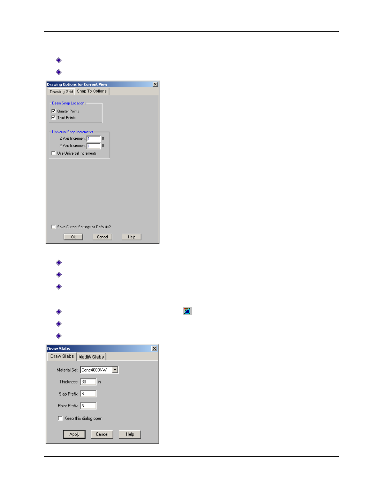
Part B: Tutorial 2 – Modeling
First, turn off the display of the loads, then turn on the Snap To Options:
On the View menu, click Loads.
On the Modify menu, click Drawing Grid. Click the Snap To Options tab.
Specify the settings for the snap:
Under Universal Snap Increments, in the Z Axis Increment and X Axis Increment boxes, type 1.
Select the Use Universal Increments check box.
Click OK.
Specify the material to be used for your slab:
On the Drawing toolbar, click Draw Slabs .
In the Material Set list, click Conc4000NW.
In the Thickness box, type 30.
91

Part B: Tutorial 2 – Modeling
Verify the dialog box settings, then apply:
Click Apply. You will now resume the drawing mode.
Draw your first, second, and third combined footing slabs:
Click the following coordinates to draw the first combined footing slab:
(-3,114) (-3,124) (24,124) (24,114) double-click this coordinate to close the slab polygon
Draw the second and third combined footing slab:
Click the following coordinates to draw the second combined footing slab:
(-3,95) (-3,105) (24,105) (24,95) double-click this coordinate to close the slab polygon
Click the following coordinates to draw the third combined footing slab:
(-3,70) (-3,80) (24,80) (24,70) double-click this coordinate to close the slab polygon
Right-click your mouse, or press ESC to exit the drawing mode.
92

Part B: Tutorial 2 – Modeling
When finished, your model should look like this:
Pedestals
Your next step is to draw pedestals on the slabs. To make this easier, start by turning off the display of
the project grid and the Data Entry toolbar. Then, use the selection tools to select just the nodes on the
lower slab.
On the Data Entry toolbar, click Close .
On the View menu, click Project Grid to turn off the Project Grid display.
On the Selection toolbar, click Unselect All to unselect the entire model. Then, click Criteria
Selection .
The Select Items for Current View dialog box will display:
93

Part B: Tutorial 2 – Modeling
Select only the nodes on the slab:
Click the Coordinates tab.
Under Coordinate Bounds, in the X Coordinate row, under Minimum, type 0, and under
Maximum, type 40.
The dialog box should now look like this:
Verify the dialog box settings, then apply:
Click OK.
Now, only the nodes on the interior of the slab are selected:
94

Part B: Tutorial 2 – Modeling
Before you continue drawing, save this selected state so that you may access it later.
On the View menu, click Save or Recall Selection States.
Click Save. Enter the description Slab Pedestals.
Click OK. Then click Close.
Finally, draw the pedestals:
On the Drawing toolbar, click Draw Pedestals .
Click Rectangular. In the D box (for depth), type 24. In the W box (for width), type 20.
In the Material Set list, click Conc4000NW.
In the Height box, type 12.
Verify the settings, then apply:
Click Apply.
Note: Your cursor will change to , indicating that you are now in the pedestal drawing mode. To exit
this mode at any time, right-click your mouse or press ESC.
95

Part B: Tutorial 2 – Modeling
Once you draw the box (and
release the mouse), notice that
pedestal icons appear over all
the nodes that were selected.
To draw the pedestals, you may click each node individually--but you may find it much faster to “box” the
nodes you just selected:
Draw a box around the selected nodes, as shown below:
Exit the drawing mode, reselect the entire model, and turn on the project grid display:
Right-click the mouse (or press ESC) to exit the drawing mode.
On the Selection toolbar, click Select All to reselect the entire model.
On the View menu, click Project Grid to turn on the project grid display.
Then apply pedestals to your combined footings. To make drawing easier, turn off the Snap To Options
and zoom in on these footings.
On the Drawing toolbar, click Universal Snap Points to turn it off.
96
 Loading...