


RISAFloor
Rapid Interactive Structural Analysis – Floor
User’s Guide
26632 Towne Centre Drive, Suite 210
Foothill Ranch, CA 92610
(949) 951-5815
(949) 951-5848 (FAX)
www.risatech.com

Copyright ©2010, RISA TECHNOLOGIES, LLC. All Rights Reserved.
No part of this publication may be reproduced or transmitted in any form or by any means,
electronic, or mechanical, including photocopying, recording, or otherwise, without the prior
written permission of RISA TECHNOLOGIES, LLC.
RISAFloor is a trademark of RISA TECHNOLOGIES, LLC. RISA, as applied to structural engineering
software, is a trademark of RISA TECHNOLOGIES, LLC.
TJI is a registered trademark of TJ International, Inc.
Trus Joist is a registered trademark of Weyerhaeuser Company Corporation.
BCI is a registered trademark of Boise Cascade Corporation.
LPI is a registered trademark of Louisiana-Pacific Corporation.
All other trademarks mentioned in this publication are the property of their respective owners.
Every effort has been made to make this publication as complete and accurate as possible, but
no warranty of fitness is implied. The concepts, methods, and examples presented in this
publication are for illustrative and educational purposes only, and are not intended to be
exhaustive or to apply to any particular engineering problem or design. The advice and
strategies contained herein may not be suitable for your situation. You should consult with a
professional where appropriate. RISA TECHNOLOGIES, LLC, assumes no liability or responsibility
to any person or company for direct or indirect damages resulting from the use of any
information contained herein.

Table of Contents
Table of Contents
Introduction .................................................................................................... 1
How to Use this Book .................................................................................................... 1
Using the Online Help ................................................................................................... 3
Technical Support Information ..................................................................................... 3
RISA Technologies Online ............................................................................................. 4
Before You Begin ............................................................................................. 5
RISAFloor Overview ...................................................................................................... 5
Hardware Requirements ............................................................................................... 5
Program Limits .............................................................................................................. 6
License Agreement ....................................................................................................... 6
Maintenance ................................................................................................................. 8
Installation .................................................................................................................... 8
RISAFloor Customization–Important Assumption! ....................................................... 8
First Look at RISAFloor ..................................................................................... 9
Starting RISAFloor ......................................................................................................... 9
The RISAFloor Windows and Dialog Boxes ................................................................... 9
Menus and Toolbars ................................................................................................... 11
Tutorial 1 – Columns & Wall Panels ................................................................ 15
Project Grid ................................................................................................................. 17
Global Parameters ...................................................................................................... 19
Drawing ....................................................................................................................... 19
Columns ...................................................................................................................... 20
Wall Panels .................................................................................................................. 27
Tutorial 2 – Modeling Beams .......................................................................... 29
Primary Framing .......................................................................................................... 30
Infill Framing ............................................................................................................... 35
Additional Beam Drawing Tips (optional) ................................................................... 39
Tutorial 3 – Decks & Slab Edges ...................................................................... 43
Creating Slab Edges ..................................................................................................... 43
Deck/Slab Properties .................................................................................................. 46
Tutorial 4 – Loading ....................................................................................... 51
Area Loads................................................................................................................... 51
Line Loads ................................................................................................................... 58
Point Loads .................................................................................................................. 63
i

Table of Contents
Tutorial 5 – Solution & Results ....................................................................... 65
Modifying the Model .................................................................................................. 70
Tutorial 6 – RISA-3D Integration ..................................................................... 73
Tutorial 7 – RISA Interoperability ................................................................... 83
RISA-Revit Structure Link ............................................................................................ 83
CIS/2 Translator .......................................................................................................... 86
RISAFloor & CAD ......................................................................................................... 87
Conclusion ................................................................................................................... 90
Appendix A – RISAFloor Toolbar Buttons ....................................................... 91
RISA Toolbar ................................................................................................................ 91
Window Toolbar ......................................................................................................... 93
Window Toolbar ......................................................................................................... 95
Drawing Toolbar .......................................................................................................... 96
Selection Toolbar ........................................................................................................ 97
ii

Introduction
Introduction
How to Use this Book
Welcome to the RISAFloor User’s Guide. If you are a first-time user of RISAFloor, we recommend
that you start with this book. This book contains seven step-by-step tutorials that guide you
through the entire modeling process using most RISAFloor features. You will create a real-world
example of building and solving a model, making changes, optimizing the model, and even
exporting to RISA-3D. Several tips and shortcuts will also be demonstrated along the way.
Begin by reviewing First Look at RISAFloor on page 9 to familiarize yourself with the toolbars and
shortcuts, then proceed to the step-by-step tutorials.
To complete all the tutorials will take only a few hours. However, you can speed up the process
even further if you skip the supporting text and concentrate only on the action steps, which are
indicated with diamond-shaped bullets, as shown below:
In order for you to achieve accurate results, it is important that you do not miss any of
these action steps while performing the tutorials.
The tutorials build upon themselves from start to finish. You have the option of performing
them all at one time, or performing each one separately. To make this possible, RISA provides
model files for you to load at the beginning of each tutorial. These starter files are located in the
RISA program folder under Tutorials, and are named Tutorial 2 starter.rfl, Tutorial 3 starter.rfl,
etc.
After you have gone through the tutorials in this RISAFloor User’s Guide, you can use Help and
the RISAFloor General Reference for complete, detailed information on every topic relating to
RISAFloor. The topics are arranged in alphabetical order and are thoroughly indexed.
You can also use the Appendix on page 91 for future reference if you need assistance with
recalling menu options, as well as button names and locations.
If you are not a first-time user and are not sure which book will be most helpful your situation,
consider that the RISAFloor User’s Guide covers how and when to apply RISAFloor features such
as steel, wood, and concrete code checks, but the specifics of how those code checks are
calculated are covered in Help and the RISAFloor General Reference.
Where to Download RISAFloor Book Updates
Every effort has been made to ensure the accuracy of this book at the time of publication. The
latest edition of all books and documents relating to this product are available in Adobe PDF
format through the World Wide Web at http://www.risatech.com, click Downloads, Product
Documentation, then RISAFloor.
1

Introduction
This convention:
Indicates:
CAPITAL LETTERS
Names of keys on the keyboard – for example, SHIFT, CTRL, or ALT.
KEY+KEY
One key should be held down and then another key pressed – for
example, CTRL+P or ALT+F4.
Bold text
Boxed text
Bulleted text
Program interface options – for example, Start button.
Notes or modeling tip information.
Action item for building the tutorial model.
Document Conventions
The following conventions are used throughout this book:
2

Introduction
Help on
general topics
On the RISA Toolbar, click the Help button . This is the fastest way to
get help on general topics. You can also go to the main menu and click
Help, then select Help Topics.
Once you enter the Help, notice the three tabs on the left: Contents,
Index, and Search. You can explore the Help by topic using either Contents
or Index, or explore the Help using your own specific keywords using
Search.
Help on a specific
feature (contextsensitive help)
As you work, notice the Help buttons at the bottom of many of the dialog
boxes. These provide direct access to the Help information related to the
task you are performing.
This context-sensitive help may be accessed by pressing the Help button
on the dialog box or by pressing the F1 key.
Help on toolbar
buttons
Are you uncertain what a toolbar button is for? Simply hold your mouse
pointer over that button (without clicking), and a description of that
button will be displayed.
Using the Online Help
Whether you need help on general topics, specific features, or toolbars, it is all built in to the
extensive RISAFloor online Help system. The RISAFloor Help was designed to enable you to
pinpoint the Help information you need quickly, by offering different ways for you to access and
locate that Help, as described below:
Technical Support Information
Technical support is an integral part of the software packages offered by RISA Technologies, and
is available to all registered licensees at no additional charge for the life of the program. The
“life of the program” is defined as the time period for which that version of the program is the
current version. In other words, whenever a new version of RISAFloor is released, the life of the
previous version is considered to be ended. Technical support is a limited resource; first priority
3

Introduction
will always be given to those clients who are current on their maintenance. See below for an
explanation of maintenance.
Before contacting technical support, you may want to take a few minutes to do the following:
Search the Help and all user documentation available for the product.
Search our FAQ database by visiting our website at http://www.risatech.com. Click on
Support, then Frequently Asked Questions, and then choose the product.
When you are ready to make a support request, please be prepared to send us your model, and
include the following information:
Your name, company name, and phone number;
Product name and serial number or Key ID;
A detailed problem description; and
Your model (filename.rfl) as an e-mail attachment, or on disc if sending via mail. If
your model contains multiple members, plates, or load combinations, please specify
which ones we should look at.
You can contact Technical Support by e-mail, phone, or by mail, as follows:
E-mail: support@risatech.com
E-mail is usually the best way to communicate with us when sending a model. Please include all
the information listed above.
Phone: (949) 951-5815 or (800) 332-RISA (7472)
Technical support personnel are available from 6:00 A.M. to 5:00 P.M. Pacific Standard Time,
Monday through Friday.
Mail:
If you prefer support via mail, please enclose all information listed above, and mail to:
RISA Technologies, Technical Support
26632 Towne Centre Drive, Suite 210
Foothill Ranch, CA 92610
RISA Technologies Online
Visit RISA Technologies on the Worldwide Web at http://www.risatech.com for:
Answers to frequently asked questions
Downloads of user documentation and tutorials
Software updates – Any known problems are posted on the website, along with
possible work-around procedures and/or service releases to update your software.
Software verification problems
4
Before You Begin
Before You Begin
RISAFloor Overview
RISAFloor has been developed to make the definition, design, and modification of floor systems
fast and easy. Analysis (including calculation of maximum deflections and stresses) may be done
on structures constructed of any material or combination of materials. Plus, complete member
design optimization is provided for hot rolled and cold formed steel, NDS wood beams, and steel
or wood products.
RISAFloor has both graphical modeling and spreadsheet input capabilities. Not only can you
draw your model, there are exceptional generation tools that automatically layout floor
elements. To modify your model input data directly, RISAFloor employs a powerful proprietary
spreadsheet tool. The combination of these features makes modeling intuitive and powerful.
The model can be rapidly edited, solved, viewed, modified, re-solved, etc. The truly interactive
nature of RISAFloor is its primary strength.
All model editing, model solution and results browsing is accomplished through the same
interface, all within RISAFloor. The interactive approach offers several unique advantages, such
as the ability to do real-time error checking of your model data, the ability to do rapid model
editing, solution, editing, and re-solution without jumping from one program to another.
Hardware Requirements
Minimum
Any Windows compatible computer with a Pentium 3 or better processor
Windows 2000/XP/Vista/7
256MB of RAM
200MB of hard disk space
Two or three button mouse
USB port (required for Stand-Alone version or Network Host computer)
Recommended
Windows XP
As much extended RAM as possible
As much free disk space as possible
Two button mouse with wheel
Note: The amount of space required by RISAFloor to solve a structural model is dependent on
the size of the model. In general, 500 Mbytes of RAM is adequate to solve most problems, but
the more the better, especially for large models. RISAFloor has been designed to use as much
available RAM as possible. If there is not enough RAM, RISAFloor will use hard drive space until
enough memory is obtained to solve the problem. However, this will cause the solution to run
much slower.
5

Before You Begin
Floors
200
Columns per Floor
1000
Beams per Floor
2000
Wall Panels per Floor
500
Material Sets
500
Custom Wood Species
500
Point Loads per Floor
2000
Line Loads per Floor
2000
Tapered Area Loads per Floor
200
Area Load Polygons per Floor
200
Deck Polygons per Floor
200
Load Combinations
5000
Program Limits
Demonstration Version: While you can open and solve a larger model, the largest model that can
be saved to disk with the demonstration version is limited to 3 floors with a maximum of 30
members for each floor.
License Agreement
END-USER LICENSE AGREEMENT FOR RISA TECHNOLOGIES® SOFTWARE
The RISAFloor software product (SOFTWARE PRODUCT) includes computer software, the associated
media, any printed materials, and any electronic documentation. By installing, copying or otherwise using
the SOFTWARE PRODUCT, you agree to be bound by the terms of this agreement. If you do not agree with
the terms of this agreement RISA Technologies is unwilling to license the SOFTWARE PRODUCT to you. In
such event you must delete any installations and destroy any copies of the SOFTWARE PRODUCT and
return the SOFTWARE PRODUCT to RISA Technologies within 30 days of purchase for a full refund.
Copyright 2010 by RISA Technologies, LLC. All rights reserved. The SOFTWARE PRODUCT is protected by
United States copyright laws and various international treaties. All rights not specifically granted under
this agreement are reserved by RISA TECHNOLOGIES.
1. SOFTWARE LICENSE. The SOFTWARE PRODUCT is licensed, not sold. All right, title and interest is and
remains vested in RISA TECHNOLOGIES. You may not rent, lease, or lend the SOFTWARE PRODUCT. You
are specifically granted a license to the use of this program on no more than one CPU at any given time.
The Network Version of the SOFTWARE PRODUCT is licensed for simultaneous use on a certain maximum
number of network stations that varies on a per license basis. As part of the license to use the SOFTWARE
PRODUCT, the program user acknowledges the reading, understanding and acceptance of all terms of this
agreement. The SOFTWARE PRODUCT may not be reviewed, compared or evaluated in any manner in any
publication without expressed written consent of RISA Technologies. You may not disassemble,
decompile, reverse engineer or modify in any way the SOFTWARE PRODUCT. If the SOFTWARE PRODUCT
was purchased at a discounted price for educational purposes it may in no event be used for professional
design purposes. The terms of this license agreement are binding in perpetuity.
6

Before You Begin
2. DISCLAIMER. We intend that the information contained in the SOFTWARE PRODUCT be accurate and
reliable, but it is entirely the responsibility of the program user to verify the accuracy and applicability of
any results obtained from the SOFTWARE PRODUCT. The SOFTWARE PRODUCT is intended for use by
professional engineers and architects who possess an understanding of structural mechanics. In no event
will RISA Technologies or its officers be liable to anyone for any damages, including any lost profits, lost
savings or lost data. In no event will RISA Technologies or its officers be liable for incidental, special,
punitive or consequential damages or professional malpractice arising out of or in connection with the
usage of the SOFTWARE PRODUCT, even if RISA Technologies or its officers have been advised of or
should be aware of the possibility of such damages. RISA TECHNOLOGIES' entire liability shall be limited to
the purchase price of the SOFTWARE PRODUCT.
3. LIMITED WARRANTY. RISA Technologies warrants that the SOFTWARE PRODUCT will operate but does
not warrant that the SOFTWARE PRODUCT will operate error free or without interruption. RISA
Technologies sole obligation and your exclusive remedy under this warranty will be to receive software
support from RISA Technologies via telephone, e-mail or fax. RISA Technologies shall only be obligated to
provide support for the most recent version of the SOFTWARE PRODUCT. If your version of the
SOFTWARE PRODUCT is not the most recent version RISA Technologies shall have no obligation to provide
support in any form. Except as stated above the SOFTWARE PRODUCT is provided without warranty,
express or implied, including without limitation the implied warranties of merchantability and fitness for a
particular purpose.
4. PROTECTION DEVICE. In the event the SOFTWARE PRODUCT requires the use of a PROTECTION DEVICE
to operate, you are specifically prohibited from attempting to bypass the functionality of the PROTECTION
DEVICE by any means. If the PROTECTION DEVICE becomes broken or inoperable it should be returned to
RISA TECHNOLOGIES for a replacement. The replacement will not be provided if RISA TECHNOLOGIES can
not affirm that the broken PROTECTION DEVICE was originally provided by RISA TECHNOLOGIES for use
with the SOFTWARE PRODUCT. A lost or stolen PROTECTION DEVICE will not be replaced by RISA
TECHNOLOGIES.
5. TERMINATION. RISA TECHNOLOGIES may terminate your right to use the SOFTWARE PRODUCT if you
fail to comply with the terms and conditions of this agreement. In such event you must delete any
installations and destroy any copies of the SOFTWARE PRODUCT and promptly return the SOFTWARE
PRODUCT to RISA Technologies.
6. CHOICE OF LAW. By entering into this Agreement in accordance with Paragraph 1, above, you have
agreed to the exclusive jurisdiction of the State and Federal courts of the State of California, USA for
resolution of any dispute you have relating to the SOFTWARE PRODUCT or related goods and services
provided by RISA Technologies. All disputes therefore shall be resolved in accordance with the laws of the
State of California, USA and all parties to this Agreement expressly agree to exclusive jurisdiction within
the State of California, USA. No choice of law rules of any jurisdiction apply.
"RISA" as applied to structural engineering software is a trademark of RISA Technologies, LLC.
"TJI" is a registered trademark of TJ International, Inc.
“Trus Joist” is a registered trademark of Weyerhaeuser Company Corporation.
"BCI" is a registered trademark of Boise Cascade Corporation.
"LPI" is a registered trademark of Louisiana-Pacific Corporation.
7

Before You Begin
Maintenance
Program maintenance provides all upgrades to RISAFloor, discounts on new products, and top
priority for technical support.
When your maintenance expires, you will be given the opportunity to continue program
maintenance on an annual basis. You are under no obligation to continue program
maintenance, of course, but if you decide to discontinue maintenance you will no longer receive
RISAFloor program upgrades and you will not be eligible for technical support once the version
of the program you ended with becomes obsolete.
Installation
Installation Instructions
To install RISAFloor, please follow these instructions:
Place the RISAFloor CD in your computer CD drive. If the CD starts automatically, skip
the remaining steps, and follow the on-screen instructions.
If the CD does not start after 10 seconds, click the Windows Start button and select
Run.
In the Run dialog box, type “d:\launchsetup” (where “d” is the label of your CD drive),
and then click the OK button.
Follow the on-screen instructions.
RISAFloor Customization–Important Assumption!
Please ensure that when performing these tutorials, RISAFloor has not been customized in any
way, and is in the default, installed state. If the installation of RISAFloor has been customized,
you may reset the program defaults as follows: on the Tools menu, and select Reset All Program
Defaults.
8
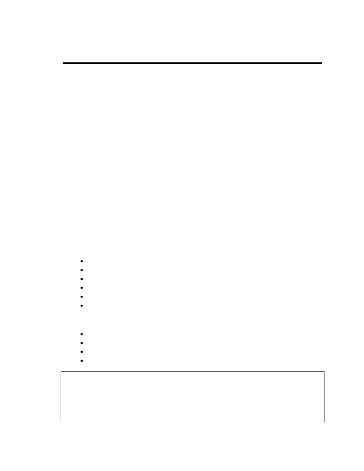
First Look at RISAFloor
Main menu
Status bar
Workspace
Title bar
Minimize Maximize Close
Starting a Model
dialog box
RISA toolbar
First Look at RISAFloor
Starting RISAFloor
This section describes the RISAFloor user interface, the toolbars and shortcuts. We recommend
that you review this section before you begin the tutorials.
Start RISAFloor as follows:
On the Start button, click All Programs, select RISA, then select RISAFloor.
The RISAFloor Windows and Dialog Boxes
9

First Look at RISAFloor
Title bar
The title bar at the top of your RISAFloor window can be very useful. Besides containing
the name of the file that is currently open, it can also be used to move the window and
minimize, maximize, and resize the window.
To move the window, press and hold the title bar with your mouse, then drag to the
desired location.
Minimize,
Maximize,
Close
The three buttons on the right of the title bar control the RISAFloor window as follows:
Click Minimize to minimize the window to a button on the taskbar, click
Click Maximize to maximize the window to full screen. Once it is full screen,
click Restore Down to restore the window down to its original size.
Click Close to close the window.
Workspace
The actual work that you do in RISAFloor will be in the main area on the screen, the
workspace. Currently the workspace is empty except for the Starting a New Model
dialog box. As you create new model views and spreadsheets they will also appear in
the workspace.
Status bar
The Status bar at the bottom of your screen will report information about your model
as you work.
If the letter “S” is dimmed, a solution has not been performed. After a solution has been
performed, the letter “S” will become blue in color with a red checkmark (as shown
below). If the “S” is yellow, this means you have solution results but there have been
modifications via the Member Redesign dialog box.
To the right of the “S” are 3 status boxes:
To the right of the “S” are 3 status boxes:
The first status box displays general information relative to the task you are
performing.
The second (middle) status box reports the units of the current spreadsheet
cell. As you move from cell to cell, look to the middle status box for the
appropriate units. This box is empty if you are not working in a spreadsheet.
The third status box (on the far right) reports the cursor coordinates as you
work in the model view. This will be demonstrated throughout the tutorial.
Dialog
boxes
Dialog boxes are windows that help you perform a specific function within RISAFloor.
For example, the Starting a Model dialog box is presented when you first open
RISAFloor, which helps you find the file you wish to open.
10

First Look at RISAFloor
File
Provides access to file operations such as opening, saving, importing, and
exporting files.
Edit
Provides editing tools that help you modify and manipulate the spreadsheets.
You may use this menu to add or remove information from the spreadsheets or
to sort and mathematically manipulate current spreadsheet data.
View
Allows you to adjust the current model view or open a new model view.
Insert
Used to insert beams, columns, wall panels, and loads into the model. All of
these items may be input graphically or entered in the spreadsheets. This menu
gives access to the graphical methods that RISAFloor provides, while the
Spreadsheet menu gives you access to the spreadsheets.
Modify
Allows access to the graphic editing features and may be used to modify
existing model elements.
Spreadsheets
Opens the spreadsheets.
Solve
Solves the model.
Results
Allows access to all analysis result spreadsheets. This button is dimmed when
no results are available, such as before you run a solution.
Tools
Provides tools to help you organize, identify, and correct problems as you
model the structure. Preferences are also located here.
Window
Manages all of the windows that you have open in RISAFloor, whether they are
spreadsheets or model views. Special tiling options are also available that relate
to specific modeling tasks.
Help
Access the RISAFloor online Help. For more information on Help, see Using the
Online Help, on page 3.
Director
Allows access between RISAFloor and RISA-3D for the design of your lateral
force resisting system.
Menus and Toolbars
Main Menu
The Main menu and its submenus provide access to all features RISAFloor has to offer, as
summarized below:
11
First Look at RISAFloor
Anytime a spreadsheet is open,
notice the window toolbar changes.
The Selection toolbar is not
visible in spreadsheet mode.
RISA toolbar – provides file operations,
printing, changing design parameters.
Window toolbar – access to
viewing commands.
Drawing toolbar
Selection toolbar – provides
tools to help make selections.
Data Entry toolbar - provides quick
access to spreadsheets (and toolbars
switch to spreadsheet view).
-OR-
Results toolbar - After the model is
solved, the Results toolbar will also
open.
In model view
In spreadsheet view
Toolbars
The most commonly used features available on the Main menu are also available on the
toolbars as toolbar buttons. The toolbars are designed to speed up your workflow by placing
these tools close to your workspace and making them easily visible.
Unlike some of the other toolbars, the RISA toolbar never changes. The other toolbars change,
depending on whether you are in model view (graphical) or spreadsheet view.
If at any time you are not sure what a particular toolbar button does, simply position your
mouse over the button and a short definition will display.
Note: You will discover many options to access the features available in RISAFloor. The methods
you choose—whether menus, toolbars, or keyboard shortcuts—will simply be a matter of
personal preference.
12

First Look at RISAFloor
RISA Toolbar
The RISA toolbar is located directly below the main menu. Unlike some of the other toolbars,
the RISA toolbar never changes. These buttons perform general actions such as opening and
closing files, changing design parameters, printing, and solving the model.
Window Toolbar
…in model view
The Window toolbar is located directly below the RISA toolbar. When working in a graphic
model view, the buttons provide model viewing tools, such as rotate and zoom, and others.
…in spreadsheet view
When you are working in a spreadsheet, this toolbar provides spreadsheet editing tools, such as
Block Fill and Block Math.
Graphic Editing (Drawing) Toolbar
The Graphic Editing toolbar (also known as the Drawing toolbar) provides tools to assist with
creating and modifying your model graphically. This toolbar may be turned on and off (CTRL+G)
as needed.
Selection Toolbar
…only visible in model view
The Selection toolbar is the vertical toolbar along the left side of the screen.
It provides selection tools to help you work with parts of the model.
You will need to make selections when you do things like graphically edit only
part of the model or print only part of the results.
Spreadsheet Toolbars (Data Entry and Results Toolbars)
These two toolbars provide access to the spreadsheets. You can
turn them on and off on the RISA toolbar by clicking the Data
Entry button or the Results button .
The Data Entry toolbar is a vertical toolbar on the right of your
13
First Look at RISAFloor
Row of cells-
Click the row label (at left)
to select the entire row
Column of cells
Scroll bar
Column label-
Click the column label to
select the entire column
screen. It looks different than the other toolbars because its
buttons consist of text instead of images.
The Results toolbar is very similar. It appears after the model has been solved and provides
quick access to the results spreadsheets.
Both toolbars allow you to access the spreadsheets very quickly while building and solving your
model. The buttons appear in the general order as you may need them.
Working in Spreadsheets
Spreadsheets are comprised of rows and columns of data cells. To add or edit data in a cell, click
on the cell, making it the active cell and then type. There is always only one active cell at a time.
This active cell is denoted in green. Notice you can change which cell is active using the LEFT
ARROW, RIGHT ARROW, PAGE UP, PAGE DOWN, HOME keys, etc.
You may also select blocks of cells to work on. To select a block of cells, click and hold the mouse
button in the first cell in the block, drag to the last cell in the block, then release the mouse. To
select an entire row or column, simply click the row or column label. To select multiple rows or
columns, click and drag the mouse across multiple row or column buttons.
14

Tutorial 1 – Columns & Wall Panels
Tutorial 1 – Columns & Wall Panels
This is the first tutorial in this series of seven designed to guide you through the entire modeling
process using most RISAFloor features.
The tutorials build upon themselves from start to finish. You have the option of performing
them all at one time, or performing each one separately. To make this possible, RISA provides
model files for you to load at the beginning of each tutorial. These starter files are located in the
RISA program folder under Tutorials, and are named Tutorial 2 starter.rfl, Tutorial 3 starter.rfl,
etc.
When you finish all seven tutorials, the final product will be this multi-material building which
you can then use to explore interaction with other programs such as RISA-3D and Autodesk®
Revit Structure®.
To complete all seven tutorials will take only a few hours. However, you can speed up the
process even further if you skip the supporting text and concentrate only on the action steps,
which are indicated with diamond-shaped bullets, as shown below:
In order for you to achieve accurate results, it is important that you do not miss any of
these action steps while performing the tutorials.
15

Tutorial 1 – Columns & Wall Panels
Now, if you are ready to get started, start RISAFloor, if you have not already done so:
Double-click on the RISAFloor icon to start the program. The Starting a Model dialog
box will display, which allows you to create a new model or open an existing file.
To create a new model, begin by creating a floor plan, as shown above, or click Close and work
on your own.
Click Create a New Floor Plan to begin.
Since this is the first floor in the model, the only option is Original Floor. After creating one or
more floors, you may then use them as the starting point for additional floors, either by creating
a Copy or a Child of an existing floor.
The Create New Floor Plan dialog box also allows you to set the Elevation, the Default Area
Load, and the Default Deck for the floor. These settings are discussed in more detail on page 47.
In the Elevation box, enter 15 ft, and then click OK.
A new, blank floor will display, along with an empty Project Grid spreadsheet.
16

Tutorial 1 – Columns & Wall Panels
Hints:
To type the values, try
using the numeric
keypad and the DOWN
ARROW key to advance
to the cell below.
You may lengthen the
window by clicking on
the bottom right corner
of the dialog box and
dragging in a downward
motion.
Project Grid
You can generate grids or type them in one at a time. To generate grids:
On the Z Axis tab, in the Increments box, type 9@30.
Click Generate to create your Z Axis project grid.
Next, modify the grid coordinates in the Distance column by typing the values shown in
the next image.
Since the grid spacing is the same for the Z Axis and the X Axis grid, copy and paste the Distance
column data as follows:
While still in the Z Axis tab, click the first cell of the Distance column and drag the cursor
down to the last row. The entire Distance column should now be highlighted in magenta
as shown above.
Press CTRL+C to copy this information to the clipboard.
Before pasting the data, select the X Axis tab and enter the following Grid Generation
information:
In the Start Label box, type J.
In the Increments box, type 9@30.
For the Label Order, click Z to A.
Click Generate.
17

Tutorial 1 – Columns & Wall Panels
To paste the copied information from the clipboard:
Verify that you are still in the X Axis tab, click Distance to select the entire column, then
press CTRL+V to paste the data into the column.
Click Close to exit the grid spreadsheet. Your workspace should like this:
Note: If you are using the demonstration version of RISAFloor to run this tutorial, you will be
unable to paste; this is a limitation of the demonstration version. Instead you will need to retype the grid data into the X-Axis tab.
18

Tutorial 1 – Columns & Wall Panels
Drawing toolbar
The toolbar buttons are arranged in
the order you would use them to
define your model (left to right).
In the Global Parameters
dialog box, you can enter
model information as well
as set design information.
There are tabs labeled
Description, Solution,
Codes, Composite, Wind,
Seismic, and Concrete.
Global Parameters
Global Parameters are settings that apply to the entire model. To view these settings:
On the RISA toolbar, click the Set Global Parameters button .
Click on each tab to review the settings (the default settings will be used for this tutorial,
so there is no need to change any of this data).
Close the Global Parameters dialog box:
Click Cancel.
Drawing
When building your model, you will define the elements in the order that they will be built. For
example, supporting elements must be in place first before you can define elements that use
those supports. You may enter model elements through the spreadsheets or with the drawing
tools. The use of drawing tools will be the focus of the next few sections of this tutorial.
The Drawing toolbar is located at the top of the workspace and looks like this:
To turn the Drawing toolbar on or off, go to the Window toolbar, and click the Graphic
Editing Toolbar button .
19

Tutorial 1 – Columns & Wall Panels
Columns
When creating columns, you may choose the material and shape of the column, as well as
designate its orientation. You may orient the column towards a specific point, give it a specific
angle, or combine the two. For this model, we will use several of these options.
On the Drawing toolbar, click Draw or Modify Columns to view the Draw Columns
dialog box.
Define the W14 gravity columns, as shown below.
Under Material, select A992.
Under Shape Group, select WF14.
Click Apply to start drawing the columns.
Note: When you enter the drawing mode, your cursor changes to .
20

Tutorial 1 – Columns & Wall Panels
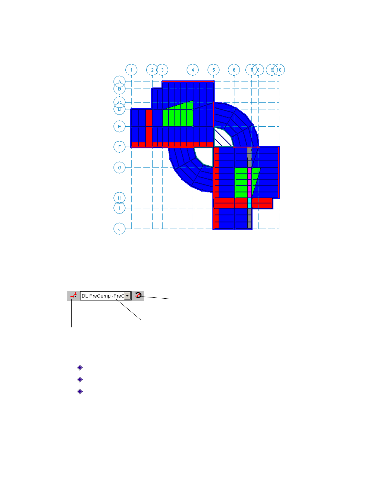
You can now start defining the columns by clicking or drawing, as shown below:
Enter columns by clicking on the F5, B2, and I9 grid locations.
Next, enter multiple columns by drawing a box around the grid intersections between
D1 and E4, as shown in the diagram below.
Repeat for the grid intersections between G6 and J7.
To further define the gravity columns:
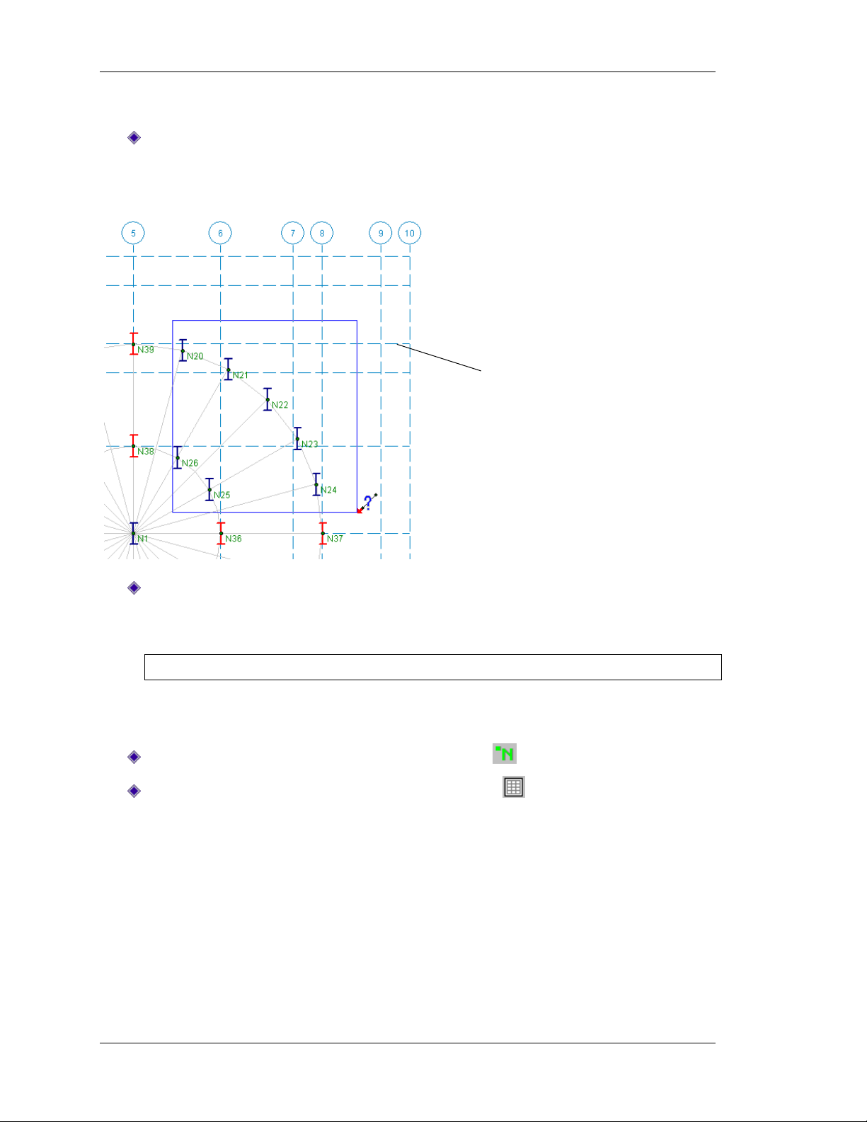
On the Drawing toolbar, click Modify Drawing Grid to create a local drawing grid.
Under Drawing Grid Origin, in the Z Axis and the X Axis boxes, type 119.
Click Radial Grid Parameters. In the Angle Increments box type 24@15, and in the
Radial Increments box type 30,35.
The dialog box should look like this:
Click Ok to close the dialog box.
21

Tutorial 1 – Columns & Wall Panels
Click the grid points to
place the columns as
shown.
Hint:
Zoom in and out using
the wheel button on
your mouse.
Now use the newly created radial drawing grid to define the gravity columns.
Create the gravity columns by clicking the radial grid points shown in the image below.
Note: If you have trouble clicking on the exact location, enlarge the model using the
wheel button on your mouse to zoom in and out.
Next, add the lateral columns:
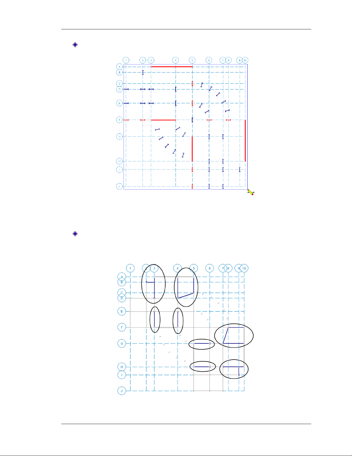
On the Drawing toolbar, click Draw or Modify Columns .
Under Function, click Lateral, and then click Apply.
Add lateral columns at C5, E5, F1, F2, F6, F8, I5, and J5, as shown in the figure below.
Note: Lateral columns are displayed in red; gravity columns are displayed in blue.
When you finish adding these columns, use the right mouse button (right-click) or ESC to
terminate the column drawing tool.
22

Tutorial 1 – Columns & Wall Panels
Notice that all the columns are oriented with their webs parallel to the vertical axis.
To change the orientation of the columns toward the center column:
On the Window toolbar, click the Joint Labels button two times to turn on the
labels of the point locations.
Make note of the point label at the center of the radial grid. That point label will be used
below to orient the columns in your radial grid.
On the Drawing toolbar, click Draw or Modify Columns again and select the Modify
Properties tab.
In the Orientation Options area, select the Use? check box (once it is selected, it will
display in red). In the Orient to Point box, enter the point label for the center of your
grid (this is the point label you made note of above).
Click Apply Entries by Clicking/Boxing Columns Individually, and then click Apply.
Note: The cursor will change to .
23
Tutorial 1 – Columns & Wall Panels
To see the orientation of the
columns change, enlarge the
model by zoom in and out using
the wheel button on your mouse.
Now, you can select the columns as follows:
Click on or draw a box around the columns in the upper portion of the radial grid, as
shown in the figure below. Note that the orientation of these columns changes toward
the center column.
Continue clicking or drawing boxes around the remaining columns in the upper and
lower portions of the radial grid, so that all columns should now be oriented toward the
center column.
Note: Use care not to select the center column, as it already has the correct orientation.
When you are finished with the radial columns, you can now turn the labels and the drawing
grid off.
On the Window toolbar, click the Joint Labels button to turn off the labels.
On the Drawing toolbar, click the Drawing Grid button to turn off the drawing grid.
24

Tutorial 1 – Columns & Wall Panels
Next, rotate the horizontal columns 90 degrees, so that they are oriented properly:
On the Drawing toolbar, click Draw or Modify Columns again. Ensure that the
Modify Properties tab is still selected.
In the Orientation Options area, click the Use? check box (once it is selected, it will
display in red). In the Orient to Point box, clear the point label and leave it blank. In the
Rotate Angle box, enter 90.
Click Apply.
Note: The cursor will once again change to .
25

Tutorial 1 – Columns & Wall Panels
Click on or draw a box around the columns circled in the next image.
When you are done, your columns should have rotated 90 degrees, and oriented as shown
below.
26

Tutorial 1 – Columns & Wall Panels
Wall Panels
Prepare to draw your wall panels:
On the Drawing toolbar, click Draw or Modify Walls .
Under Function, click Lateral. The wall panel settings should match those in the image
below. Click Apply.
Note: Your cursor will change to .
Start drawing your wall panels, as follows:
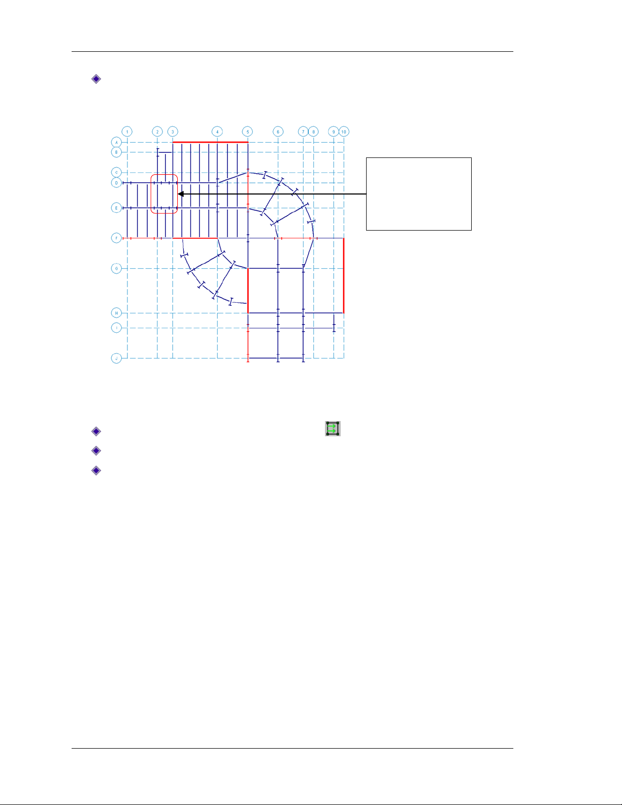
Draw in a wall panel between A3 and A5. To do this, click on A3, move the mouse to A5
and click again.
Note: After you draw a wall, your cursor is “anchored” to the end point of the wall. To
release the drawing tool, use your right mouse (right-click) or ESC.
Draw the remaining wall panels between F3 and F4, G5 and H5, and F10 and H10.
If you make a mistake or if you want to delete a wall, click CTRL+Z to undo, or delete the wall as
follows: on the Modify menu, click Delete, then click Delete Based on This Criteria and check
the Delete Selected Walls check box.
For more details on how to model wall panels, including information on wall openings, masonry
design and wood design, refer to http://www.risatech.com/d_documentation.html.
27

Tutorial 1 – Columns & Wall Panels
When you’re finished your model should look similar to the following image:
This is the end of Tutorial 1.
You may save your model to be used as the starting point for the next tutorial, or begin the next
tutorial using the .rfl starter file in the RISAFloor Tutorials folder. To save the model:
On the File menu, click Save As and enter a file name. Note that it will have an .rfl
extension.
28

Tutorial 2 – Modeling Beams
Tutorial 2 – Modeling Beams
This tutorial will guide you through drawing individual beams and explore the different timesaving options for adding infill beams. This tutorial continues from where the previous tutorial
ended, so follow these steps to get your model up and running:
If you are continuing from the previous tutorial, you can skip ahead to the next step.
-OR-
If you are starting here from scratch, follow the steps below to load the starter file
provided by RISA Technologies:
Double-click on the RISAFloor icon to start the program.
Click Open Model . Double-click the Tutorials folder, select Tutorial 2 Starter.rfl and
click Open. Click Close (or Cancel) to exit the Global Parameters dialog box.
On the Window toolbar, click the Graphic Editing Toolbar button to activate the
Drawing toolbar.
Your screen should now look like this:
29

Tutorial 2 – Modeling Beams
Primary Framing
On the Drawing toolbar, click Draw or Modify Beams to open the Draw Beams
dialog box.
In this dialog box, materials and shapes may be chosen along with orientation options. You may
also assign the beams to a set of design rules. You may draw single span members or continuous
beams. For this model, we will select a wide flange, hot rolled steel member drawn point to
point.
Under Material, select A992; under Shape Group, select Wide Flange; and under Design
Rules, select Typical.
Click Apply.
Note: The cursor will change to to signify that you are now in drawing mode.
30
Tutorial 2 – Modeling Beams
Draw a box around the entire model, as shown in the figure below:
Notice that some beams were not automatically drawn in, such as those supported by wall
panels or other beams. These members can be drawn individually, without going back to the
dialog box.
Draw in the 14 beams circled below by clicking from point to point. Start by clicking A3,
then D3. Use the right mouse button (right-click) or press ESC to release the mouse
between clicks. Then click B2 and B3. Continue by clicking to draw the remaining beams.
31

Tutorial 2 – Modeling Beams
Tips:
Use the wheel button on your
mouse to zoom in and out.
If you terminate the beam draw
tool before you are finished, you
may recall it by clicking the Draw
or Modify Beams button or
CTRL+D.
The beams in the radial portion of the structure may also be drawn from point to point.
Continue clicking from point to point to draw in the beams shown below.
On the Drawing toolbar, click Modify Drawing Grid .
Click the Snap To Options tab.
Under Universal Snap Increments, make sure the Z Axis and X Axis Increments are both
set to 1 ft. Check the Use Universal Increments check box (this will allow you to draw
freehand without being limited to a project or drawing grid).
Click Ok to return to the model view.
Notes: On the Drawing toolbar, the Universal Snap Points button should be pressed in. The
cursor should indicate that you are still in a beam drawing mode . If not, you may recall it
any time by clicking Draw or Modify Beams or by pressing CTRL+D.
32

Tutorial 2 – Modeling Beams
Now, draw in two beams beginning at (54, 119) and (119, 54), as shown circled in the
image below. To help you locate the coordinates, zoom in using your mouse roller.
Notice that as you move your cursor around a point, the coordinates are displayed on
the Status bar at the bottom of your screen (on the right).
When you finish drawing the beams, your model should look like this:
On the Drawing toolbar, click the Universal Snap Points button to turn it off.
Lastly, change the function of the beams that span between the lateral columns and make them
lateral elements.
On the Drawing toolbar, click Draw or Modify Beams and select the Modify
Properties tab.
In the Function area, select the Use? check box (once it is selected, it will display in red).
Under Function, click Lateral.
Click Apply Entries by Clicking Beams Individually, and then click Apply.
33

Tutorial 2 – Modeling Beams
Now, click on the 4 beams that are shown circled in the image below (you can click
anywhere on the beams).
Note: The color for these beams will change from blue to red because you are changing their
function.
Your model should now look like this:
34

Tutorial 2 – Modeling Beams
Infill Framing
RISAFloor’s Infill Framing tool assists your design process by quickly generating beams within
existing bays. This tool will help you quickly create all of your secondary members:
On the Drawing toolbar, click Generate Beams .
Under Material, select A992.
Under Beam Orientation, click Vertical, and then click Apply.
35
Tutorial 2 – Modeling Beams
Notice that one bay
was purposely left
empty. This will be
used later in the
tutorial.
Click once inside each open bay to fill in (as shown in the image below) until the upper
left side of model looks like this:
If you zoom out to view a larger portion of your model, you can generate secondary beams in
multiple bays at once.
On the Drawing toolbar, click Generate Beams again.
Under Beam Orientation, click Horizontal, and then click Apply.
Draw a box around the area between grid lines F5 and J10 to select the entire area.
36

Tutorial 2 – Modeling Beams
When finished, your model should look similar to the one shown below:
You can also use this tool to generate infill beams that are parallel to an adjacent member.
On the Drawing toolbar, click Generate Beams .
Under Beam Orientation, click Angle to a Beam, then enter an angle of 0.
Click Apply.
First click on the bay you want to fill in and then click on the member that the new
beams should be parallel to, as shown in the diagrams below.
1st Click 2nd Click
37

Tutorial 2 – Modeling Beams
Continue with other bays until the radial portion of your model is similar to that shown
below:
Terminate the drawing tool using the right mouse button (right-click) or press ESC.
38

Tutorial 2 – Modeling Beams
Additional Beam Drawing Tips (optional)
Before moving on, we recommend exploring some of the other beam modeling tools provided
in RISAFloor. The steps in the remainder of this tutorial are optional, but you may find them very
helpful to master.
The first tool will demonstrate how to add ten members by simply clicking on two end points.
On the Drawing toolbar, click the Draw or Modify Beams button again.
Click the Draw Beams tab, make sure that the Keep spans continuous (as drawn) check
box is NOT checked, then click Apply.
Click at the start of the first beam (C2) and drag to the end of the last beam (C5). Right-
click to release the mouse.
Your model should now look like the image below. The single span beams will be automatically
broken at the supports for you.
Since these members should not be a part of your completed model, click the Undo
button to undo the creation of the beams.
Note: When drawing new members, you may create either single or continuous span members.
If the Keep spans continuous check box had been selected, RISAFloor would have created a
continuous beam that spanned from C2 to C5.
39

Tutorial 2 – Modeling Beams
Another useful tool is the ability to offset beams from the end of another parallel beam:
On the Drawing toolbar, click the Draw or Modify Beams button to again open the
Draw Beams dialog box.
Under Drawing Options, click Draw Beam to Beam. In both the 1
st
Offset and 2nd Offset
boxes, enter 5 ft, and then click Apply.
Experiment with this tool by clicking to create members parallel to the diagonal beam
between D4 and C5, as shown in the image below.
These offsets are automatically taken from the end of the beam that is closest to where you
clicked.
Click the Undo button to undo the creation of the beams.
40
Tutorial 2 – Modeling Beams
Lastly, we’ll explore the quarter and third snap points on members, which can be a very
powerful tool.
On the Drawing toolbar, click the Modify Drawing Grid button and select the Snap
To Options tab.
Under Beam/Wall Snap Locations, make sure that the Quarter Points and Third Points
check boxes are checked.
Under Universal Snap Increments, make sure that the Use Universal Increments check
box is cleared.
Click Ok.
This allows you to draw to the quarter or third points of any beam or wall as a drawing point in
your model. Use this tool to add the diagonal beams shown in the image below.
On the Drawing toolbar, click the Draw or Modify Beams button again to open the
Draw Beams dialog box.
Under Drawing Options, select Draw Point to Point, and click Apply.
Draw by clicking in the member from the quarter point of one beam, and dragging to
the half point of another. Right-click to release the mouse.
Note: The Status bar (in the lower right hand corner of the screen) reports not only the
coordinates of your cursor, but also the half, third, and quarter point locations.
This tool eliminates the need to manually manipulate your Project or Drawing Grids.
41

Tutorial 2 – Modeling Beams
Click the Undo button several times to undo the creation of the beams.
This is the end of Tutorial 2.
You may save your model to be used as the starting point for the next tutorial, or begin the next
tutorial using the .rfl starter file in the RISAFloor Tutorials folder. To save the model:
On the File menu, click Save As and enter a file name.
42

Tutorial 3 – Decks & Slab Edges
Tutorial 3 – Decks & Slab Edges
This tutorial will guide you through adding a slab edge, editing deck properties, and drawing in
deck loads.
If you are continuing from the previous tutorial, you can skip ahead to the next step.
-OR-
If you are starting here from scratch, follow the steps below to load the starter file
provided by RISA Technologies:
Double-click on the RISAFloor icon to start the program.
Click Open Model . Double-click the Tutorials folder, select Tutorial 3 Starter.rfl and
click Open. Click Close (or Cancel) to exit the Global Parameters dialog box.
On the Window toolbar, click the Graphic Editing Toolbar button to activate the
Drawing toolbar.
Your screen should now look like this:
Creating Slab Edges
RISAFloor provides tools to create or manipulate your slab edges. To select the entire model and
create a new slab edge:
On the Selection toolbar, click the Select All button to make sure the entire model is
selected.
43
Tutorial 3 – Decks & Slab Edges
Tip:
When creating slab edges, you
can also use the selection tools to
unselect any elements that you
do not want inside the slab edge.
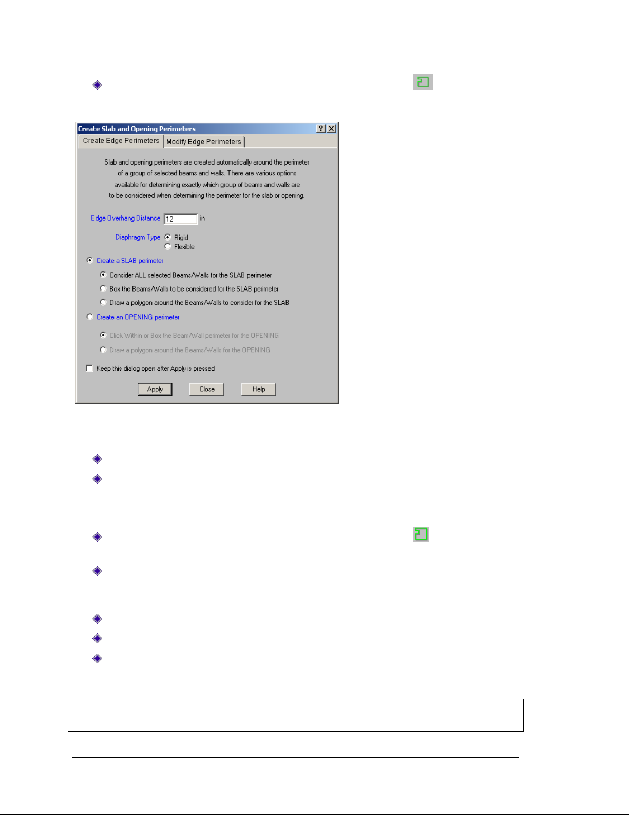
On the Drawing toolbar, click the Create Edge Perimeters button to open the
following dialog box.
Since the entire model is selected, your new slab edge will encompass all the defined beams and
walls.
Click Create a SLAB perimeter.
Click Apply to automatically create edges using the default settings.
Also, when defining slab edges, you may box the elements or draw the edges yourself. This
feature can help you select opening areas in your slab.
On the Drawing toolbar, click the Create Edge Perimeters button to open the dialog
box again.
Select Create an OPENING perimeter. When creating openings, you will primarily use
the first option to click within the bays for the opening. The second option may be used
when there are members that frame through the opening.
Select Click Within or Box the Beam/Wall perimeter for the OPENING.
Select the Keep this dialog open after Apply is pressed check box.
Click Apply.
The Create Slab and Opening Perimeters dialog box should remain open.
Note: If the dialog box is covering any portion of your model, you can move it by clicking on the
title bar and dragging it out of the way.
44

Tutorial 3 – Decks & Slab Edges
Click in the bay, as shown below.
Go back to the dialog box and select Draw a Polygon Around the Beams/Walls for the
OPENING, then click Apply.
Draw a polygon around the opening, as shown image below. When your polygon is
complete, double-click to close it off.
45
Tutorial 3 – Decks & Slab Edges
When finished, use the right mouse button (right-click) or press ESC to terminate the
drawing tool.
Click Close to exit the dialog box.
You have now created your slab edge. The next step is to review and/or modify the deck
properties that are assigned to it.
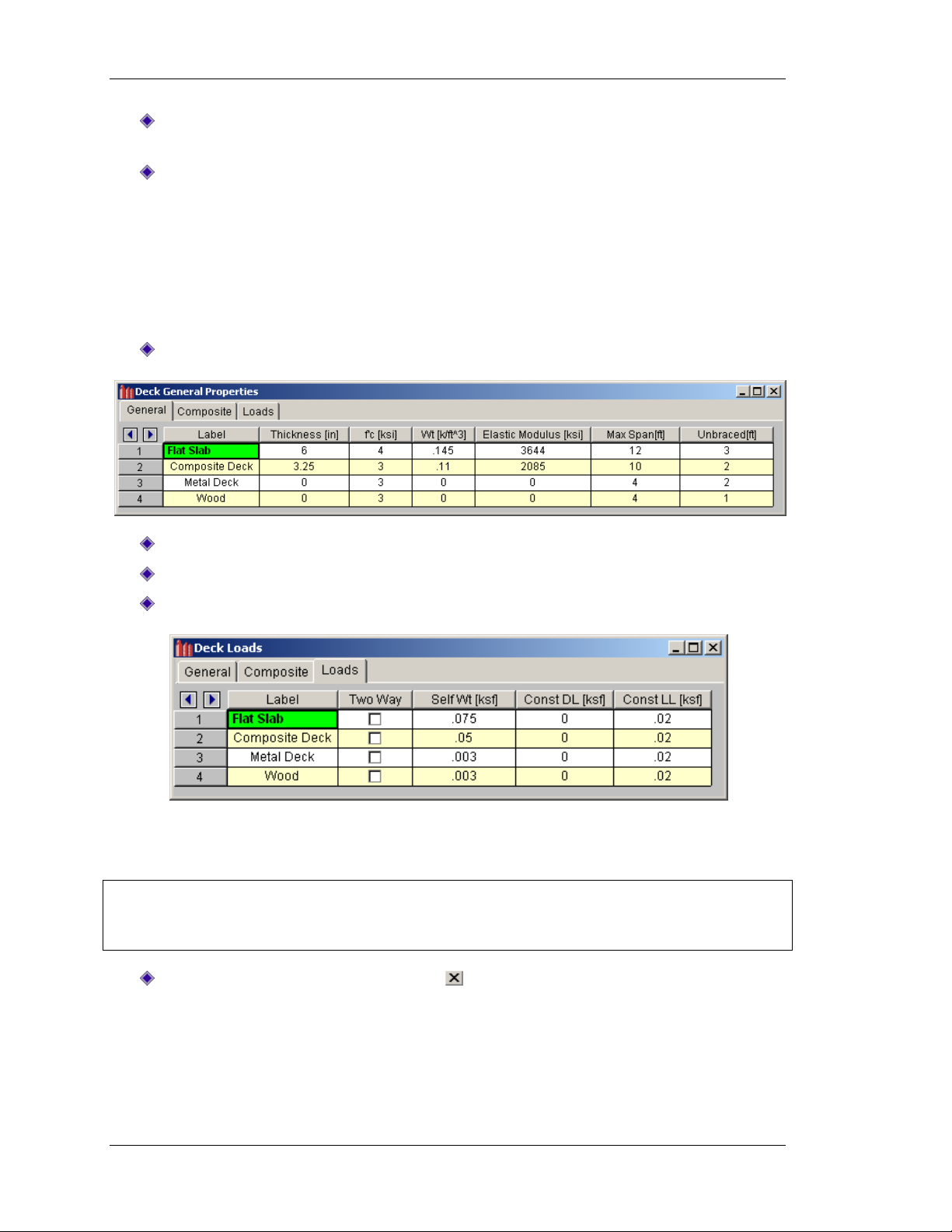
Deck/Slab Properties
To specify the properties of the deck, it is important to understand a little about how the deck
spreadsheet works:
On the Main menu, click Spreadsheets, select Deck Properties.
For the Flat Slab deck, change Max Span to 12 ft, as shown above.
For the Composite Deck, verify the data is identical to that shown above.
Next, click the Loads tab and review the information shown.
The self weight of the deck and the construction dead and construction live loads may all be
specified in the Loads tab.
Note: The loads in the Loads tab of the Deck spreadsheet are different from the area loads
defined in the Area Loads spreadsheet because these loads are specifically linked to the type of
deck construction.
Close the spreadsheet by clicking Close .
46

Tutorial 3 – Decks & Slab Edges
The deck loads shown in the previous figure are also sufficient for this example. Next, you will
learn how to apply these properties to your floor.
Each floor has a default deck and deck angle that will be used for the entire floor if no other
deck is defined. To review and modify these defaults:
On the Main menu, select Spreadsheet and click Floors.
Under Area Load Default, select Office.
Under Deck Default, select Composite Deck.
Under Deck Angle Default, enter 0.
Unless you specifically assign a new area load or deck to a region of the floor, these default
properties will be assumed:
Since your model has some areas where the default slab and orientation are not appropriate,
assign a new deck angle to these areas:
Click Close to exit the spreadsheet and return to the model view.
On the Drawing toolbar, select the Assign Slab and Deck Properties button .
In the Deck Type box, select Composite Deck.
Under Deck Direction, click Parallel to X Axis.
Click Apply.
Draw a box around the area between F5 and J10 as shown in the following image:
47

Tutorial 3 – Decks & Slab Edges
The color of the hatch marks
identifies what type of deck is
assigned and the direction of the
hatching coincides with the
general span direction of the
deck. This hatching will show
angles at intervals of 45 degrees.
If you use a deck angle that is
not a multiple of 45 degrees, the
closest multiple will be used.
This is a good visual confirmation
of the decks you have applied to
your floor. In the area where no
local deck is applied, the default
deck will be used. In areas where
more than one local deck is
applied, the top deck (the last
one drawn) will be used.
Press CTRL+D to reopen the Deck Assignment dialog box.
In the Deck Type box, select Flat Slab.
Under Deck Direction, click Angle from Z Axis, and enter an angle of 45 degrees.
Click Apply.
Assign this data to the two radial portions of your model by boxing them as shown in
the image below.
48

Tutorial 3 – Decks & Slab Edges
When you are finished drawing in your deck, your screen should like the image shown below.
RISAFloor gives you two ways to plot the deck. The first is to plot the deck properties as they are
defined. The second is to view them as they are resolved by the solver and applied to the
members. We are going to view the loads as applied:
On the Main menu, click View, select Plot Options.
Select the Points/Decks/Slabs tab.
Make sure the Show Deck Assignments check box is selected, click As Applied, and then
click OK.
49

Tutorial 3 – Decks & Slab Edges
Your display should change to look like the following image:
Notice the differences between this plot and the previous plot. In this plot, you can verify the
location of openings.
Move your mouse over the various decks. Notice the deck type and orientation
information are displayed in the Status bar as you move the cursor.
If your mouse cursor is still shown as the deck drawing cursor, use the right mouse
(right-click) or ESC to terminate this drawing tool.
Since the next section deals with area loads, you can turn off the deck display:
On the Main menu, click View, select Plot Options.
Select the Points/Decks/Slabs tab.
Clear the Show Deck Assignments check box, and then click OK to close the dialog box.
This is the end of Tutorial 3.
You may save your model to be used as the starting point for the next tutorial, or begin the next
tutorial using the .rfl starter file in the RISAFloor Tutorials folder. To save the model:
On the File menu, click Save As and enter a file name.
50

Tutorial 4 – Loading
Tutorial 4 – Loading
This tutorial will guide you through editing and adding the various types of loads available in
RISAFloor.
If you are continuing from the previous tutorial, you can skip ahead to the next step.
-OR-
If you are starting here from scratch, follow the steps below to load the starter file
provided by RISA Technologies:
Double-click on the RISAFloor icon to start the program.
Click Open Model . Double-click the Tutorials folder, select Tutorial 4 Starter.rfl and
click Open. Click Close (or Cancel) to exit the Global Parameters dialog box.
On the Window toolbar, click the Graphic Editing Toolbar button to activate the
Drawing toolbar.
Your screen should now look like this:
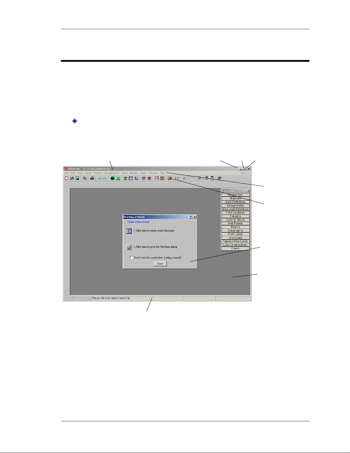
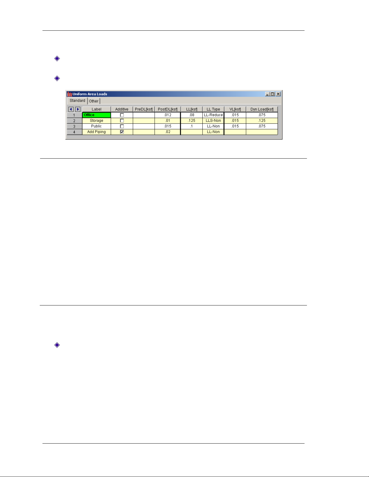
Area Loads
Area load magnitudes are defined in a spreadsheet and then applied to the floor as polygons,
much like the deck properties in the previous section. Area loads that are within the slab edges
(but not inside an opening) are automatically attributed in the deck direction to the beams and
walls and then reduced for member design according to the live load reduction methods chosen
in Global Parameters.
51
Tutorial 4 – Loading
Label
The name you will later use to refer to the load when you apply or view it.
Additive
If this is checked, the load applied will add to the load that is graphically beneath
it in the order of application.
PreDL
PostDL
LL
LL Type
These entries allow you to specify load magnitudes for different categories that
will later be used in the load combinations that you solve.
PreDL and PostDL are for dead loads that are pre- and post-composite.
Remember that other dead loads (deck self weight and construction
dead load) were already defined within the deck definitions spreadsheet.
LL and LL Type load columns are for the live load magnitude, and the
type of live load which you may choose from a list.
VL
Dyn Load
Specifies the vibration load. The vibration load (along with the self weight of the
beam and deck) will be used for calculating the mass for a vibration check, per
AISC Design Guide #11.
The dynamic load will be used to determine the diaphragm mass and mass
moment of inertia for a RISA-3D seismic analysis.
Edit the Area Loads spreadsheet, as shown below:
On the Main menu, click Spreadsheets, select Loads, and then select Area Load
Definitions.
Edit the load information to match what is shown in the image below:
The entries in the Area Loads spreadsheet are described below:
Each floor has a default area load that will be used within the entire floor slab if no other load is
specified. You can review this information as follows: on the Main menu, click Spreadsheet,
then select Floors. The Area Load Default is set to Office. To use different loads in an area, you
can graphically define local area loads.
Click Close to exit the spreadsheets and return to the model view.
52

Tutorial 4 – Loading
These two options allow you to apply the load
automatically by clicking or drawing a polygon
around the members which define the area.
-OR-
This option allows you to draw the polygon
manually by clicking on points.
Notice you also have the option of drawing in a
tapered area load. This can be useful for modeling
certain types of snow loads, but will not be used in
this tutorial. For more information on tapered area
loads refer to RISAFloor General Reference.
To apply local area loads:
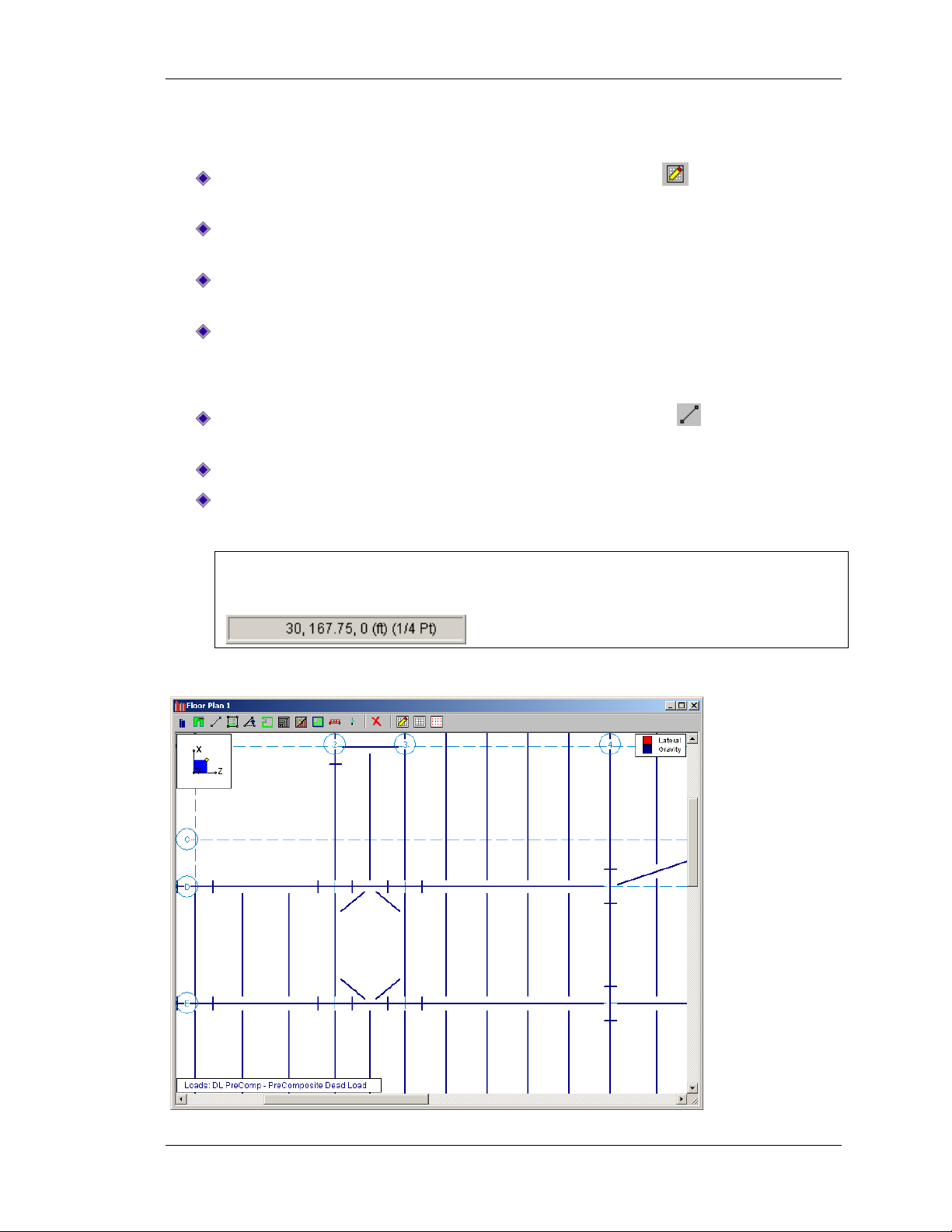
On the Drawing toolbar, click the Draw Area Loads button to display the following
dialog box:
Draw the area loads:
Under Uniform Area Loads, in the Area Load box, select Storage, then select the Point
to Point Draw of the Area.
Click Apply.
Note: The cursor will change to .
53

Tutorial 4 – Loading
Coordinates of this point:
(187.33, 89) (1/3rd Pt)
Coordinates of this point:
(89, 187.33) (1/3rd Pt)
Draw the polygons for the two area loads by clicking on points, as shown in the
following figure.
Tip: When you are in drawing mode, you can automatically snap to the quarter and third points
of any beam (as demonstrated in the previous tutorial).
Press CTRL+D to reopen the Create Area Loads dialog box.
Under Uniform Area Loads, in the Area Load box, select Public, then select the Point to
Point Draw of the Area.
Click Apply.
54

Tutorial 4 – Loading
The blank areas where you have
not drawn in a load will receive the
default Office load automatically.
Area Load edges are
at the quarter point
locations.
Draw in the public area loads, shown in the next image.
When you are finished drawing area loads, your screen should look like the image shown below.
Note: Loads do not have to start or end on project grid lines. In areas where more than one load
is applied, the top load (the last one drawn) will be used by RISAFloor. The exception to this is
that any additive load will be applied along with the load beneath it.
Press CTRL+D to reopen the Create Area Loads dialog box.
Under Uniform Area Loads, in the Area Load box, select Add Piping.
Click Apply.
55
Tutorial 4 – Loading
This load is bounded either by
the quarter point of the beam
or by the project grid points.
Since the piping was specified
as additive, this new load will
be automatically combined
with the other existing loads.
Coordinate location:
(167.75, 119)
Draw in a piping load that overlaps the other loads, as shown in the image below, by
clicking on points.
RISAFloor gives you two ways to plot the area loads. The first is to view them as they were input.
The second is to view them as they are resolved and applied by RISAFloor. We are going to view
them as applied.
To plot the area loads:
On the Main menu, click View, select Plot Options.
Select the Loads tab.
Make sure the Uniform Area Loads check box is selected, click As Applied, and then
click Apply.
In the Show Loads for Category box, select DL PostComp. Click OK to exit.
56
Tutorial 4 – Loading
Toggle between load categories
and load combinations.
Select the various load categories
or combinations.
Toggle the display of
the loads on and off.
Your screen should look similar to the figure shown below:
Notice that the default Office load was applied automatically and that no area load is applied to
the two slab openings. Also, note that the additive piping load was automatically combined with
the Office, Public, and Storage loads that it crossed.
On the Window toolbar, you can use these three controls to manipulate the display of your
loads:
Turn off the display of the area loads, as follows:
On the Main menu, click View, select Plot Options.
Click the Loads tab, and then click to clear the Uniform Area Loads check box.
Click OK.
57

Tutorial 4 – Loading
Line Loads
You can use line loads to model the weight of cladding, partitions, architectural components,
etc. Prepare to draw in line loads as follows:
On the Drawing toolbar, select the Line Loads button .
Enter the information as it appears in the following figure:
Click Apply.
Note: The cursor will change to .
To see the model better while you are drawing in the load, change to an isometric view and
zoom in:
On the Window toolbar, click on the Isometric button .
Click the Zoom buttons to zoom in on the right hand portion of the floor as shown in the
next image.
58

Tutorial 4 – Loading
Draw in the load by clicking on the two points, as shown in the image below. When
finished, right-click to release the mouse.
When you are finished, notice that you have specified a tapered line load to represent a nonstructural partition. The line load spans diagonally across the deck. This is important because it
will actually result in parabolic loading of the supporting beams.
To return to a planar view and continue:
Use the right mouse button (right-click) or press ESC to exit the drawing mode.
On the Window toolbar, click the Planar button .
On the Window toolbar, click Redraw to return to a full view.
Next, the loads need to be modeled due to the exterior cladding. To do this, apply a uniform
load of 2.5 kips/ft to all beams on the perimeter of the building. RISAFloor provides a selection
tool that makes this easy.
59

Tutorial 4 – Loading
First, unselect your entire model and make the following selection changes:
On the Selection toolbar, click UnSelect All to unselect your entire model.
Also on the Selection toolbar, click on the Selection Criteria button . The Select
Items for Current View dialog box will open.
Click the Beams tab and select the Perimeter Beams Only check box.
Under Selection Options, click Select Beams.
Click OK to apply the selection.
Notice that only the exterior beams of the building are selected. Also notice that you have
selected two beams that only run along the perimeter for a portion of their length. You must
apply your cladding to these beams separately.
60

Tutorial 4 – Loading
Unselect each of the beams circled below by clicking on them.
On the Drawing toolbar, select the Line Load button again to open the Floor Line
Loads dialog box.
For the DL Post load, enter a starting and ending magnitude of 2.5 kip/ft.
Under What happens when Apply is pressed?, click Apply to All Selected
Members/Walls.
Click Apply.
Your structure should look like this:
61

Tutorial 4 – Loading
Now, add the last two cladding loads.
Press CTRL+D to re-open the Floor Line Loads dialog box.
Click Apply Line Load by Drawing Point to Point.
Click Apply.
Draw in the line loads between A3 and B3 by clicking each point. Use your right mouse
button (right-click) or press ESC to release your mouse after drawing each load.
Draw in the line loads between H9 and H10 by clicking each point.
62

Tutorial 4 – Loading
Point Loads
Prepare to apply point loads:
On the Selection toolbar, click Select All to select the model.
On the Drawing toolbar, click Assign point loads .
Enter the information show below, and click Apply.
Since some of your loads are located in the middle of a deck span, it will be helpful to turn on
the universal drawing snap points and zoom in on your model:
On the Drawing toolbar, click the Universal Snap Points button .
Zoom in significantly on the left side portion of the floor using the mouse roller, as
shown in the next image.
Draw in the point loads:
Use the coordinates (notice they are displayed in the Status bar) and the snap points to
draw in a point load at each of the following coordinates:
(0,149)
(5,143)
(5,155)
(25,143)
(25,155)
(30, 149)
63

Tutorial 4 – Loading
When you are finished, your screen should look like this:
Note: Point loads that are applied inside the deck edges may be applied anywhere on the deck
and will be attributed automatically to the beams, walls, and columns. However, if they are
applied outside of deck edges or within deck openings, they must be applied directly on beams,
walls or columns.
This is the end of Tutorial 4.
You may save your model to be used as the starting point for the next tutorial, or begin the next
tutorial using the .rfl starter file in the RISAFloor Tutorials folder. To save the model:
On the File menu, click Save As and enter a file name.
64

Tutorial 5 – Solution & Results
Tutorial 5 – Solution & Results
This tutorial will guide you through generating load combinations, running a solution, design
optimization, and reviewing the results.
If you are continuing from the previous tutorial, you can skip ahead to the next step.
-OR-
If you are starting here from scratch, follow the steps below to load the starter file
provided by RISA Technologies:
Double-click on the RISAFloor icon to start the program.
Click Open Model . Double-click the Tutorials folder, select Tutorial 5 Starter.rfl and
click Open. Click Close (or Cancel) to exit the Global Parameters dialog box.
On the Window toolbar, click the Graphic Editing Toolbar button to activate the
Drawing toolbar.
Your screen should now look like this:
RISAFloor solves load combinations that are defined in the Load Combinations spreadsheet. As
RISAFloor designs members, it chooses members that satisfy the codes specified in the Global
Parameters and the rules that are defined in the Design Rules spreadsheet.
65

Tutorial 5 – Solution & Results
To view the load combinations:
On the Main menu, click Spreadsheets, select Load Combinations. The following
spreadsheet will appear.
On the Combinations tab, you will combine and factor the various loads that you have already
applied to your model.
Press the F4 key twice to delete the two default load combinations.
Now that you have a spreadsheet open, notice the Window toolbar looks different.
On the Window toolbar, click the LC Generator button . The Load
Combination Generator dialog box will be used to generate the load combinations
needed to design the model.
For this tutorial, assume that in the regions where this project will be built, the governing roof
loads are usually roof live load, rather than snow or rain.
Click to clear the SL and RL check boxes so that you will not be generating more load
combinations than are needed.
In the Load Combination Region list, select United States.
In the Load Combination Code list, select ASCE 2005 ASD.
Click Generate.
The following load combinations will be generated by RISAFloor:
Notice there are really two sets (categories) of load combinations. The first two (Load
Combinations 1 and 2, above) use pre-composite loads only. The other five (Load Combinations
3-7) combine the total dead load with the various live loads that may be applied to your model.
Click the Design tab to review the remaining information associated with these pre-
generated load combinations.
66

Tutorial 5 – Solution & Results
You do not have any wood members defined in your model. However, notice that the CD
column (load duration factor) is automatically adjusted for the ASD load combinations typically
used for wood design. Also notice that you can specify which load combination can be applied to
a specified material.
Click the LC Generator button .
In the Load Combination Code list, select ACI Strength 05.
Click Generate.
This finalizes your load combinations as shown below:
Notice you have total control of the design of all member types using the check boxes. The
design of the Hot Rolled Steel members will only be performed for load combinations 1-7. The
design of the Concrete members (if you had any) would only be performed for load
combinations 8-14.
To solve the model:
On the Main menu, click Solve.
Note: To optimize the beam design, this solution process may have to be repeated a few times.
When the solution is finished, the chosen member sizes are displayed on the plot (or, if you are
in rendered mode, the model is rendered with the sizes) and the solution Warning Log is
displayed.
67
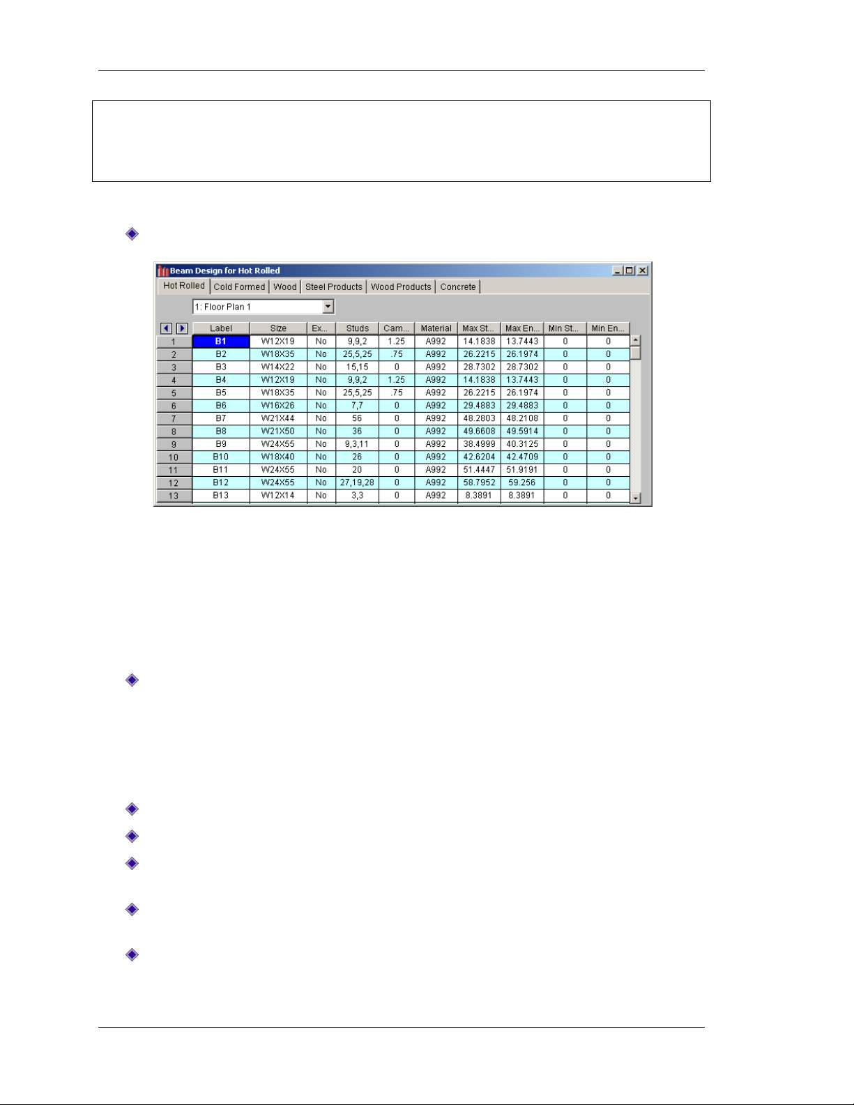
Tutorial 5 – Solution & Results
Note: The purpose of the Warning Log is to inform you whenever a modeling issue or error
arises which affects the design of the floor. For example, the first entry is informing you that you
have exceeded the maximum deck span, including the actual coordinates where the deck span
violation occurred. This will be helpful later when optimizing your design.
For now, open the Design Results spreadsheet:
On the Main menu, click Results and select Designs.
The Design Results spreadsheet summarizes all members across all material types (each
material type is contained in tabs at the top). The Hot Rolled tab lists a summary of the member
design complete with the number of studs, camber, and end reactions. Similar information
would be found under the Cold Formed or Wood tabs if any such members were contained in
this structure. Similarly, design information for Steel and Wood Joists, if used in the model,
would be found under the Steel Products or Wood Products tabs.
You may open the other spreadsheets to review the other types of results.
On the Main menu, click Results, select Code Checks, Shear, Bending, etc.
The Code Check spreadsheet gives you a quick overview of the checks for bending, deflection,
and shear. There are also individual results spreadsheets that give detailed information for the
Bending, Deflection, Shear, and Vibration checks. The Reactions spreadsheet gives the member
end reactions for the governing load categories.
Return to your model view to explore the graphic result viewing options:
On the Main menu, click Window and select 1 Floor Plan 1.
On the Main menu, click View, and select Plot Options.
Click the Beam/Columns/Walls tab. Under Line Draw, in the Color Basis list, select Defl
Limit.
Under Show Beams (the check box should already be selected), in the Labeling list,
select No Labeling.
Click Apply.
68

Tutorial 5 – Solution & Results
Your plot should now look like this:
This image gives a quick graphical representation of the adequacy of each beam for the
deflection limits specified in the Design Rules spreadsheet. You can create a similar plot to
display the Bending or Shear Checks. You can also plot the Vibration Frequencies and
Accelerations to check your entire floor system for the AISC Vibration criteria.
Click Cancel to exit the dialog box and return to your model view.
Click the Box Zoom button and select the portion of the model where the most
obvious deck span violation occurred, as shown in the figure below:
69

Tutorial 5 – Solution & Results
This detail report is shown for
Dead Load. To change categories,
use the list at the upper left.
Use the LC/Cat button to switch
from Load Categories to Load
Combinations.
Use the buttons to view the next
or previous member.
On the Selection toolbar (left side), click the Detail button .
Note: Your cursor will change to .
Click any one of the members that surround the gap in your framing (shown boxed in
the image above). This will display the member detail report for that member.
Click on a few other members and review the detail reports for those members.
The detail report displays loading information, shear, moment, and deflection diagrams. It also
gives design data, composite member properties, and the calculated allowable stresses. Since
the model had a triangular dead load that was angled to the deck, it produced a parabolic load
on the beam M18 (shown above). RISAFloor can accurately approximate this load pattern by
modeling a series of partial length trapezoidal loads.
This type of loading is common whenever you have partial length area loads, or tapered line
loads that do not run orthogonal to the deck span or beam framing. Since it can result in
significant increases in a member’s maximum moment and end reactions, it is important to
provide an accurate representation of this load.
Click Close to return to the model view before proceeding to the next section.
Modifying the Model
Now that you have reviewed all the data, it is time to make some changes to your model. Just as
in RISA-3D, modifying the model may be done graphically or within the spreadsheets. Although
this tutorial will concentrate on the graphical methods, remember that you may view and edit
most data from within the spreadsheets also.
70

Tutorial 5 – Solution & Results
To perform an interactive redesign on any member:
On the Selection toolbar, click the Design button , then click on any member.
This will open the Member Redesign dialog box, as shown below. You can scroll through the
available shapes and see how the bending, shear, and deflection are affected. To modify the
selected beam, simply click Apply. This interactive redesign is powerful because you are free to
manipulate your model without erasing all of your design results. Keep in mind that when you
are finished with all of your modifications, be sure to re-run your analysis to recalculate changes
in self weight and relative floor stiffness.
Click Cancel to close the dialog box.
You can now make a framing change to your model.
On the Window toolbar, click the Graphic Editing Toolbar button to activate the
Drawing toolbar if it is not already visable.
On the Drawing toolbar, click Draw or Modify Beams .
This is the same button that you initially used to draw the beams. When you click on this button,
a warning box will appear informing you that continuing with the operation will clear your
design results.
71
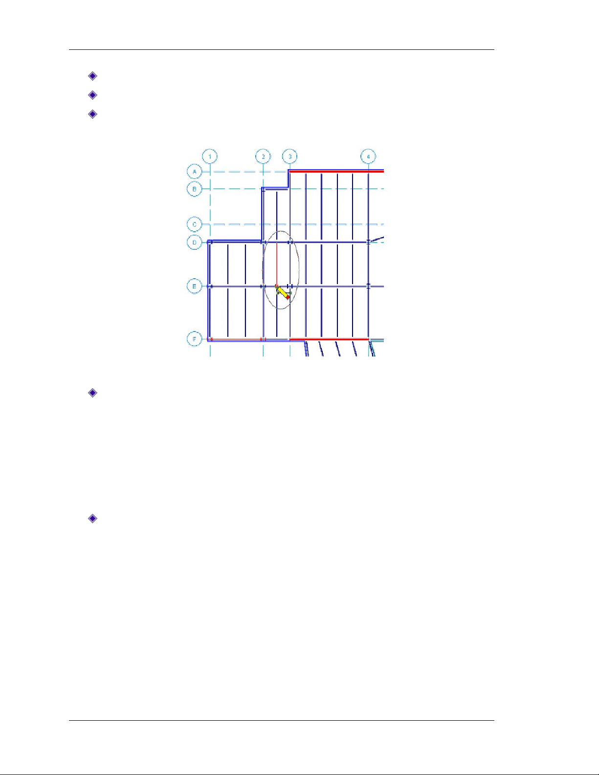
Tutorial 5 – Solution & Results
Since you are finished browsing the results, select Yes to continue.
Click the Draw Beams tab. Under Function click Gravity, and then click Apply.
Draw in the member, as shown circled below, by clicking on the two end points.
Right-click to release the mouse.
Before you end, check the spreadsheet warning log:
On the Main menu, click Spreadsheets, select Warning Log.
Notice that even though you have cleared your results, RISAFloor maintains the Warning Log to
assist you when modifying your model.
This is the end of Tutorial 5.
You may save your model to be used as the starting point for the next tutorial, or begin the next
tutorial using the .rfl starter file in the RISAFloor Tutorials folder. To save the model:
On the File menu, click Save As and enter a file name.
72

Tutorial 6 – RISA-3D Integration
Tutorial 6 – RISA-3D Integration
This tutorial is intended to introduce you to the features of RISA-3D that directly relate to its
interaction with RISAFloor. For more detailed information on RISA-3D, refer to the RISA-3D
User’s Guide and RISA-3D General Reference.
If you are continuing from the previous tutorial, you can skip ahead to the next step.
-OR-
If you are starting here from scratch, follow the steps below to load the starter file
provided by RISA Technologies:
Double-click on the RISAFloor icon to start the program.
Click Open Model . Double-click the Tutorials folder, select Tutorial 6 Starter.rfl and
click Open. Click Close (or Cancel) to exit the Global Parameters dialog box.
On the Window toolbar, click the Graphic Editing Toolbar button to activate the
Drawing toolbar.
To see the interaction between RISAFloor and RISA-3D, solve your RISAFloor model, and then
use RISA-3D to analyze and design your lateral system.
On the RISA toolbar, solve the model by clicking Solve .
On the Main menu, click the Director button (top right) and select RISA-3D.
When you enter into RISA-3D you will be prompted for information on the wind and seismic
loads of your structure.
73

Tutorial 6 – RISA-3D integration
First, the Wind Loads dialog box will display:
Review the information shown in the Wind Loads dialog box. In the future, if you make any
changes in the Wind Load Parameters area, be sure to click Calc Loads to recalculate.
Be sure to also check the information generated in the Wind Load Results area. This is a
summary of the wind loads that have been calculated for you.
Click OK to accept the loads.
74

Tutorial 6 – RISA-3D Integration
After the Wind Loads dialog box closes, the Seismic Loads dialog box will display:
Review the information shown in the Seismic Loads dialog box. In the future, if you make any
changes in the Seismic Load Parameters area, be sure to click Calc Loads to recalculate.
Be sure to also check the information generated in the Seismic Load Results area. This gives the
equivalent static force distribution and base shear that have been calculated for you.
Click OK to accept the loads.
If the Global Parameters dialog box displays, close it by clicking OK or Cancel.
75

Tutorial 6 – RISA-3D integration
An isometric view of your model will now be displayed in RISA-3D. Although the interface looks
very similar to that of RISAFloor, you are now working completely in RISA-3D.
Your screen should now look like this:
Before doing any graphical editing, turn off the joint labels:
On the Window toolbar, click the Joint Labels button .
To display and review the load data:
Turn on model rendering by clicking the Rendering button twice.
On the Main menu, click Spreadsheets, select Basic Load Cases. You can now review the
load data that was generated.
76

Tutorial 6 – RISA-3D Integration
As you review the data in this spreadsheet, notice that all your basic load cases have been
created for you, including wind and seismic load cases for each direction.
When you are finished reviewing the data, click Close to close the spreadsheet and
return to your model view.
Diaphragms are also created in RISA-3D based on your floor slabs from RISAFloor:
On the Data Entry toolbar (at right), click Diaphragms.
Notice that the diaphragms already contain the diaphragm mass and mass moment of inertia
information that you would need for a dynamic analysis. In this spreadsheet, you can specify the
percent of width you want RISA-3D to use to account for the accidental eccentricity in the X or Z
directions.
Click Close to exit the Diaphragms spreadsheet and return to the model view.
77

Tutorial 6 – RISA-3D integration
On the Window toolbar, click on the Diaphragm Display button .
This will display the RISAFloor diaphragms which have been automatically created for you.
Notice that only the beams, columns, and wall panels that were specified as LATERAL members
were generated in your RISA-3D model. You can always add vertical braces, modify your wall
panels, or manipulate your model as you wish.
Next, add some X bracing, as follows:
On the Window toolbar, click the Graphic Editing Toolbar button to activate the
Drawing toolbar.
On the Drawing toolbar, click the Draw New Members button . The Draw Members
dialog box will appear.
78

Tutorial 6 – RISA-3D Integration
Click Assign Shape Directly. Under Start Shape, type HSS4x4x4, under Design List, select
Tube, and under Type, select VBrace.
In the Release Codes area, click Pinned at Both Ends.
Click Apply.
Draw in the X braces (as shown in the image below) by clicking and dragging from one
point to the next. Right-click to release the mouse when needed.
79

Tutorial 6 – RISA-3D integration
Next, add the common load combinations used for this type of model, including all the code
required eccentric loadings for wind and seismic loads. This will demonstrate how the program
automatically generates these load combinations; saving you the time and energy normally
spent entering them manually.
On the Data Entry toolbar, click on Load Combinations to open the Load Combinations
spreadsheet.
Although you previously generated load combinations for your RISAFloor model, you will now
generate your lateral load combinations for use in the RISA-3D model.
On the Window toolbar, click the LC Generator button to display the following dialog
box.
On the first (Gravity) tab, in the Load Combination Region list, select United States.
On the first (Gravity) tab, in the Load Combination Code list, select ASCE 2005 ASD.
Click on the Wind tab.
Under Wind Load Options, click X and Z w/Eccentric (make sure the Reversible check
box is cleared).
80

Tutorial 6 – RISA-3D Integration
Resize the window
by clicking and
dragging
downward on the
bottom right
corner, if
necessary, to see
more of the load
combinations.
Click on the Seismic tab.
Under Seismic Load Options, click X and Z w/Eccentric (make sure the Reversible check
box is cleared).
Click Generate.
This will generate the 68 load combinations shown below.
Why so many load combinations? Each code load combination that includes an earthquake or
wind load becomes six load combinations when you include all the possible eccentric cases (if
you had selected the Reversible option, this would have expanded to 12 cases).
The LC Generator feature allows complete control over whether or not to include these more
detailed load combinations. Load combinations or categories that are not relevant to your
region can be completely eliminated by modifying the provided .xml spreadsheets.
81

Tutorial 6 – RISA-3D integration
For example, if you are in a year-round sunny climate like south Florida, do you really need to
check your structure for all the combinations that include snow load? Therefore, to remove the
snow loads from your generated load combinations, locate and modify the spreadsheet. The
United States spreadsheet is located in C:\RISA\risa_LC_lists and is named United States.xml.
Note: Before editing this file, you may want to copy the original in case you want to restore all
the settings back to the default.
As you can see from this tutorial, the interaction between RISAFloor and RISA-3D is completely
seamless and the interfaces of these two programs are quite similar. However, this tutorial is
only an introduction to the many features of RISA-3D. We recommend downloading the RISA-3D
User’s Guide for tutorials demonstrating the features of this powerful program.
Another option is that you can run your model in RISA-3D to resize your beams and columns.
Then, return to RISAFloor to see how all those changes have been incorporated in the RISAFloor
model for gravity load analysis.
This is the end of Tutorial 6.
You may save your model if you choose, but it is not necessary for the next tutorial. If you
choose to save your model:
On the File menu, click Save As and enter a file name.
Note: You will notice that this file saves as a RISAFloor (.rfl) model, even though we have now
been working in RISA-3D. This is because the file contains RISAFloor data that would be lost if
the RISA-3D file were detached. To reopen the file in the future, you will need to open it in
RISAFloor, solve, and use the Director tool to bring it back into RISA-3D.
82

Tutorial 7 – RISA Interoperability
Tutorial 7 – RISA Interoperability
RISAFloor has several options for importing or exporting projects to and from other industry
software. This tutorial will introduce you to several of those options.
RISA-Revit Structure Link
Because the RISA-Revit link is a bi-directional exchange link, new models can be created in either
RISAFloor or Revit Structure and edited in either program.
Start by exploring the export options from RISAFloor to Revit Structure. If you do not have the
RISA-Revit link, you may download it at no cost from our website. Here are instructions on how
to install the link:
Click Close to exit RISAFloor if you have the program open.
Go to http://www.risatech.com/partners/prt_revit.html, click Downloads, and then
select the RISA-Revit version you want to download.
Download and install the link.
Follow the steps below to load the RISAFloor starter file for this tutorial:
Double-click on the RISAFloor icon to start the program.
Click Open Model . Double-click the Tutorials folder, select Tutorial 7 Starter.rfl and
click Open. Click Close (or Cancel) to exit the Global Parameters dialog box.
Solve the model and save:
Click Solve to solve the model.
On the File menu, click Save As and enter a new file name.
83

Tutorial 7 – Interoperability
Your model should now display design data such as member sizes, end forces, and number of
studs:
On the Main menu, click File, click Export, then select BIM Exchange File, and designate
a name for your exchange file.
Close RISAFloor by selecting Exit from the File menu on the Main menu.
You can now open Revit Structure and import this exchange file:
Open a new file in Revit Structure.
On the Main menu, Save the file as Tutorial7.rvt as the file name.
Note: This tutorial is based on the RISA interface with Revit Structure 2010. If you are
running a different version of Revit Structure, the interaction is slightly different. Please
see our website for information and instructions on how to use that version:
http://www.risatech.com/partners/prt_revit.html.
Open a 3D Analytical view.
On the Main menu, click Add-Ins, and select Import from RISA.
84

Tutorial 7 – RISA Interoperability
Click RISAFloor, and then click Browse to locate the BIM (.exc) exchange file, as shown
below.
Once in Revit Structure, you can modify your model and then export back to RISAFloor. Because
of its two way functionality, you can modify the model in either program and the other will
recognize the updates.
This was just a basic description of the RISA-Revit Link export option. For more information, you
may download documentation from the RISA website specific to the link and how to use it.
Go to the RISA website: http://www.risatech.com/partners/prt_revit.html, click Downloads,
under RISA-Revit Link Documentation, select a document to download, either RISA-Revit Link
Documentation or RISA-Revit Quick Tips.
85

Tutorial 7 – Interoperability
CIS/2 Translator
The RISA CIS/2 Translator is a tool for transferring data from RISA to the CIM steel part 21 file
format. There are two basic modes for the CIS/2 Translator: export and import. Currently
RISAFloor only exports data using the export mode. You may download this translator at no cost
from the RISA website.
Here are instructions on how to install the translator:
Click Close to exit RISAFloor if it is open.
Go to http://www.risatech.com/products.html, click RISA CIS/2 Translator to download
the translator.
Install the translator.
To open the RISA CIS/2 Translator:
From the Start Menu, select All Programs, click RISA, and then click RISA CIS/2
Translator. A dialog box will display.
Enter the following information to match the image below:
Click RUN.
The Export.stp file is now available to import into your steel detailing software.
This was a very basic description of the CIS/2 Translator. For more detailed information on the
translator and how to use it, please see the RISA CIS/2 Translator General Reference, available
for download from the RISA website: http://www.risatech.com/d_documentation.html.
86

Tutorial 7 – RISA Interoperability
RISAFloor & CAD
RISAFloor offers a DXF import/export feature that provides two-way compatibility with any
other program that can read and write DXF files--this includes most major CAD programs and
many analysis programs. With this feature, RISAFloor is able to produce CAD-quality drawings
that list your beam sizes, camber, stud layout, end reactions, etc.
Follow the steps below to load the RISAFloor starter file for this portion of the tutorial:
Double-click on the RISAFloor icon to start the program.
Click Open Model . Double-click the Tutorials folder, select Tutorial 7 Starter.rfl and
click Open. Click Close (or Cancel) to exit the Global Parameters dialog box.
Solve the model and save:
Click Solve to solve the model.
On the File menu, click Save As and enter a new file name.
Your model should now display design data such as member sizes, end forces, and number of
studs.
On the Main menu, click File, click Export, and select DXF File.
87
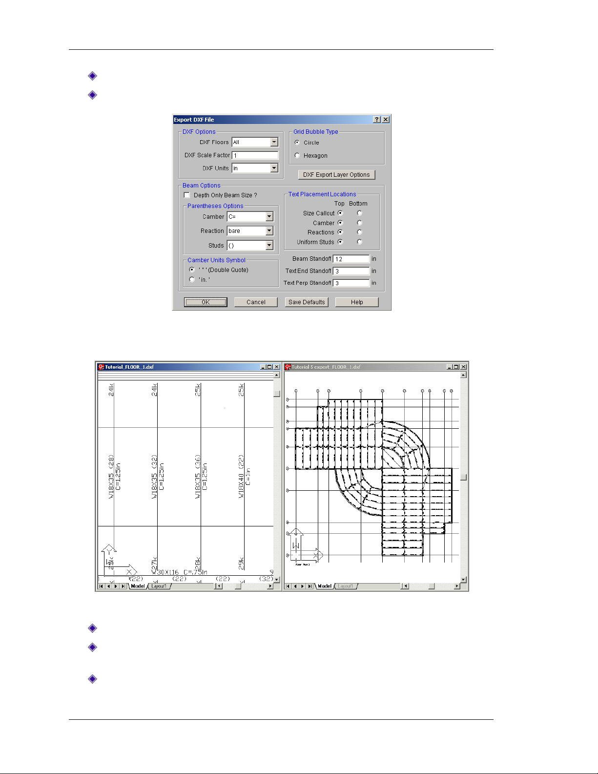
Tutorial 7 – Interoperability
Enter the file name Tutorial and click Save. The Export DXF File dialog box will display.
Enter the information shown below and click OK.
You should be able to open this DXF file with any standard drafting package. The following is an
example of the information that can be written to the drawing file.
Similarly, you can import a DXF file into RISAFloor for analysis.
On the RISA toolbar, click on New Model to start a fresh model.
Because you want to import geometry rather than start from scratch, click Close to exit
the Starting a Model dialog box.
On the Main menu, click File, click Import, then select DXF File.
88

Tutorial 7 – RISA Interoperability
Select the tutorial file you recently exported and saved. It should be named
Tutorial_FLOOR_1.dxf.
The Import DXF File dialog box will open.
Enter the information shown below:
Click OK. Your model will import and open a new floor from the imported DXF file.
This is the end of Tutorial 7.
89

Tutorial 7 – Interoperability
Conclusion
Congratulations on completing your introductory tour of RISAFloor! The time you invested in
performing these tutorials is time well spent. We are confident that the knowledge gained by
taking the time to step through these tutorials will increase your productivity, and allow you to
complete future projects more quickly and efficiently.
If you have any questions or comments, please contact us by phone at (800) 332-7472, fax at
(949) 951-5848, or email at info@risatech.com.
90

Appendix A – RISAFloor Toolbar Buttons
Button
Title
Label in RISAFloor
Shortcut
New Model
Start a new model
Start a new model
(CTRL+N)
Open Model
Open an existing model
Reload a previously
saved model
Save
Save current model to disk
Save the current model
(CTRL+S)
Copy
Copy to the clipboard
Copy to the clipboard
(Ctrl+C)
Print
Print a report or graphic image
Print a report or graphic
image
(Ctrl+P)
Undo
Undo the last operation
Undo the last operation
(Ctrl+Z)
Redo
Reverse the most recent undo
operation
Redo the most recent
undo operation
(Ctrl+Y)
Global Parameters
Design parameters that apply
to the whole model
Set Global Parameters
Define Units
Define units to be used
Define units to be used
Shape Database
Edit the shape database
Open/edit the shape
database
Rebar Layout
Create and edit a rebar layout
Create/edit a rebar
layout
Appendix A –
RISAFloor Toolbar Buttons
RISA Toolbar
91

Appendix A – RISAFloor Toolbar Buttons
Project Grid
Open project grid spreadsheet
Open the Project Grid
spreadsheet
New Floor Plan
Create a new floor plan
Create a new floor plan
Delete Floor Plan
Delete selected floor
plans
New Model View
Create a new model view
Create a new model
view
Open Spreadsheets
Select spreadsheets to open
Select spreadsheets to
open
Refresh
Refresh all windows with
current data
Refresh all windows
with the most current
data
Load Combinations
Open load combinations
spreadsheet
Open the Load
Combinations
spreadsheet
Solve
Perform the analysis and
design calculations
Perform the analysis
and design calculations
Browse Results
Select results to browse
Select results to browse
Erase Results
Erase all solution results
Erase all solution results
Data Entry toolbar
Turn the spreadsheet shortcuts
window on or off
Turn the spreadsheet
shortcuts window off or
on
Results toolbar
Turn the results shortcuts
window on or off
Turn the results
shortcuts window off or
on
Help
View help topics
View Help topics
92

Appendix A – RISAFloor Toolbar Buttons
Button
Title
Label in RISAFloor
Shortcut
Plot Options
Bring up the plot options
dialog
F2 Isometric
Display an isometric view
Snap to an isometric view
Planar
Display an XZ planar view
Snap to an XZ planar view
Rotate buttons
Rotate the view counterclockwise about the X axis
Rotate the view clockwise
about the X axis
Rotate the view counterclockwise about the Y axis
Rotate the view clockwise
about the Y axis
Rotate the view counterclockwise about the Z axis
Rotate the view clockwise
about the Z axis
Zoom buttons
Zoom IN (closer view) on
the model
PLUS (+)
Zoom OUT (view farther
away) on the model
MINUS (-)
Draw a box around the
part of the model to be
zoomed
Redraw
Redraw full model view
Redraw full model view
Graphic Editing Toolbar
Activate the graphic editing
(or drawing) toolbar
Activate the Graphic
Editing (Drawing) toolbar
Ctrl+G
Window Toolbar
…in Model view
93

Appendix A – RISAFloor Toolbar Buttons
Save View
Save or recall view states
Save or recall view states
Clone View
Make an exact copy of
current model view
Clone (make an exact
copy of) the current
model view
Display Loads
Toggle display of the loads
(LC or CAT)
Toggle display of the loads
(LC or CAT)
Switch Loads
Switch loads display
(combinations or
categories)
Switch loads display
between combinations
and categories
Rendering
Toggle between wireframe
and rendering of beams and
plates
Toggle between
wireframe and rendering
of beams and plates
Joint Labels
Joint labels toggle
Toggle the joint labels on
or off
Beam Labels
Show beam labels
Toggle beam labels on or
off
Global Axes
Toggle the global axes icon
Toggle the global axes
icon on or off
Project Grid
Toggle display of the project
grid
Toggle display of the
project grid on or off
Black and White
Toggle between black and
white backgrounds
Toggle between black and
white backgrounds
Show Member Ends
Show member end options
Show member end
options (pinned, fixed,
etc.)
94

Appendix A – RISAFloor Toolbar Buttons
Button
Title
Label in RISAFloor
Shortcut
New Line
Insert a new line before
the current line
Insert a new line before
the currently selected line
F3
Delete Line
Delete the current line
Delete the currently
selected line
F4
Sort
Sort the Current Column
Sort based on the values
in the currently selected
column
F9
Find
Find an Item
Find a particular Item in a
spreadsheet
F5
Fill
Fill the currently marked
block
Fill the currently marked
block of selected cells
Ctrl+F
Math
Perform math on the
currently marked block
Perform math on the
currently marked block of
selected cells
Ctrl+M
Mark Lines
Mark all the lines
Mark (highlight) all the
lines in a spreadsheet
Delete Lines
Delete the currently
marked lines
Delete the currently
marked lines
Ctrl+D
Unmark Lines
Unmark all the lines
UNmark all the lines
Ctrl+L
Paste
Paste from the clipboard
Paste from the clipboard
Ctrl+V
Help
Help on the current
window
Help for the current
window
SHIFT+F1
Window Toolbar
…in Spreadsheet View
95
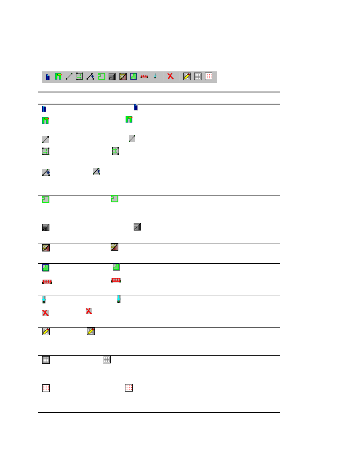
Appendix A – RISAFloor Toolbar Buttons
Button
Title
Label in RISAFloor
Shortcut
Draw or Modify Columns
Draw or modify columns
Draw or Modify Walls
Draw or modify wall
panels
Draw or Modify Beams
Draw or modify beams
Generate Beams
Generate beams within bays
Generate infill beams
within bays
Elevation
Change elevation of selected
joints
Change the elevation of
selected joints in the
model
Edge Perimeters
Create or modify edge
perimeters
Create or modify edge
perimeters
Slab and Deck Properties
Assign slab and deck properties
Assign slab and deck
properties
New Diaphragm
Add new diaphragm regions
Add new diaphragm
regions
Draw Area Loads
Draw area loads
Ctrl+D
Draw Line Loads
Draw line loads point to point
Draw line loads point to
point
Assign Point Loads
Assign point loads
Delete
Delete parts of the floor plan
Delete parts of the floor
plan
Modify
Modify the drawing grid and
snap points
Modify the drawing grid
and snap points
Drawing Grid
Toggle the drawing grid on or
off
Toggle the drawing grid
on or off
Universal Snap Points
Toggle the universal snap points
on or off
Toggle the universal snap
points on or off
Drawing Toolbar
…in model view
96
 Loading...