


RISAFloor
Rapid Interactive Structural Analysis – Floor Systems
Version 5.0 – General Reference
26632 Towne Centre Drive, Suite 210
Foothill Ranch, California 92610
(949) 951-5815
(949) 951-5848 (FAX)
www.risatech.com

Copyright 2010 by RISA Technologies, LLC All rights reserved. No portion of the contents of this
publication may be reproduced or transmitted in any means without the express written permission of
RISA Technologies, LLC.
We have done our best to insure that the material found in this publication is both useful and accurate.
However, please be aware that errors may exist in this publication, and that RISA Technologies, LLC
makes no guarantees concerning accuracy of the information found here or in the use to which it may be
put.

Table of Contents
General Reference Manual
I
Table of Contents
Before You Begin ............................................... 1
Overview ........................................................... 1
Hardware Requirements .................................. 1
Program Limits ................................................. 2
License Agreement .......................................... 2
Maintenance ..................................................... 3
Installation ........................................................ 4
Application Interface ......................................... 5
Main Menu ........................................................ 5
Shortcut Menu .................................................. 8
Toolbars ............................................................ 8
Dynamic View Controls .................................... 11
Shortcut Keys and Hot Keys ............................ 12
Status Bar ......................................................... 13
Windows ........................................................... 14
Modes ............................................................... 14
Beams ................................................................. 16
Shear Results ................................................... 35
Bending Results ............................................... 35
Column Results ................................................ 36
Assumptions and Limitations ............................ 37
Special Messages ............................................ 38
Columns .............................................................. 39
Drawing Columns ............................................. 40
Modifying Column Properties ........................... 41
Modifying Column Design Parameters ............. 42
Column Stacks and Physical Columns ............. 43
Columns Spreadsheet ...................................... 44
Column Stacks Spreadsheet ............................ 47
Column Stack Manager .................................... 48
Columns – Results............................................. 51
Column Forces ................................................. 51
Concrete – Database ......................................... 55
Rebar Layout Database .................................... 55
Drawing Beams ................................................ 17
Drawing Infill Beams ......................................... 18
Modifying Beam Properties .............................. 20
Modifying Beam Design Parameters ................ 21
Beams – Primary Data ..................................... 22
Beams Spreadsheet – Detailing Data .............. 23
Beams – Results ................................................ 24
Beam Deflection Results .................................. 24
Beam End Reactions ........................................ 25
Beam Vibration Results .................................... 26
Cold Formed Steel – Databases ....................... 27
Custom vs. Manufacturer Shapes .................... 27
Cold Formed Shape Types .............................. 28
Cold Formed Steel – Design ............................. 30
Design Parameters ........................................... 30
Phi Factors ....................................................... 33
Design Results ................................................. 33
Concrete – Design ............................................. 60
Concrete Spans ................................................ 60
Concrete Design Parameters – Columns ......... 60
Concrete Design Parameters – Beams ............ 62
T-beam & L-beam Sections .............................. 64
Parabolic vs. Rectangular Stress Blocks .......... 64
Biaxial Bending of Columns .............................. 65
Limitations – General ........................................ 66
Limitations – ACI .............................................. 66
Limitations – Canadian Code ........................... 66
Limitations – Australian and NZ Codes ............ 66
Limitations – British .......................................... 67
Limitations – Euro ............................................. 67
Limitations – Indian ........................................... 67
Limitations – Saudi Code .................................. 67
Special Messages ............................................ 67
Concrete – Design Results ............................... 69
Code Checks .................................................... 34
Beam Results ................................................... 69

Table of Contents
II
RISAFloor v5.0
Column Results ................................................ 74
File Operations ................................................... 114
Concrete Detail Reports ................................... 76
Beam Detail Reports ........................................ 76
Column Detail Reports ..................................... 78
Customizing RISAFloor .................................... 81
Save as Defaults .............................................. 81
Preferences ...................................................... 81
Decks and Slabs ................................................ 86
Creating Slab Edges and Openings ................. 86
Modifying Slab Edges and Openings ............... 87
Assigning Slab and Deck Properties ................ 88
Deck Properties – General ............................... 89
Deck Properties – Composite ........................... 90
Deck Properties – Loads .................................. 92
Slab Edge and Opening Perimeters ................. 92
Design Optimization .......................................... 93
Design Lists ...................................................... 93
Design Rules – Size / U.C. ............................... 94
Starting Off........................................................ 114
Importing and Exporting Files ........................... 114
Automatic Backup ............................................. 114
Floors .................................................................. 116
Creating a New Floor ........................................ 116
Deleting a Floor ................................................ 116
Floors Spreadsheet .......................................... 117
Parent / Child .................................................... 118
Global Parameters ............................................. 119
Description ........................................................ 119
Solution ............................................................. 120
Codes ............................................................... 121
Composite ......................................................... 123
Wind .................................................................. 124
Seismic ............................................................. 125
Concrete ........................................................... 126
Graphic Display.................................................. 128
Design Rules – Deflection ................................ 95
Design Rules – Concrete Rebar....................... 96
Design Rules – Masonry Walls ........................ 97
Design Rules – Wood Wall (Studs) .................. 98
Design Rules – Wood Wall (Fasteners) ........... 99
Design Rules – Diaphragms ............................. 100
Member Redesign Dialog ................................. 100
Optimization Procedure – Walls ....................... 101
Diaphragms ........................................................ 102
Rigid Diaphragms ............................................. 102
Semi-Rigid Diaphragms ................................... 103
Flexible Diaphragms ......................................... 103
Diaphragms Spreadsheet ................................. 104
Diaphragm Modeling Tips ................................ 105
DXF Files ............................................................ 107
Importing DXF Files .......................................... 107
Exporting DXF Files ......................................... 109
Multiple Windows .............................................. 128
Controlling the Model View ............................... 129
Viewing Part of the Model ................................. 131
Saving and Retrieving Model Views ................. 131
Graphic Display – Plot Options ........................ 132
Beams/Columns/Walls ..................................... 132
Points/Decks/Slabs ........................................... 133
Loads ................................................................ 134
Miscellaneous ................................................... 135
Graphic Editing .................................................. 137
Drawing and Modification Features .................. 137
Undo Operations .............................................. 138
Redo Operations .............................................. 138
Project Grid ....................................................... 138
Drawing Grid ..................................................... 140
Snap Points ...................................................... 143
Deleting Elements ............................................ 144
DXF Element Numbers .................................... 111
DXF File Format ............................................... 111
Graphic Selection .............................................. 146
Selection Modes ............................................... 146

Table of Contents
General Reference Manual
III
Inverting Selections .......................................... 147
Effective Width Calculation ............................... 169
Criteria Selections ............................................ 147
Locking Selections ........................................... 151
Graphic Selection from Spreadsheets ............. 151
Saving Selections ............................................. 152
Help Options ...................................................... 153
Electronic Help File .......................................... 153
Context Sensitive Help ..................................... 153
RISA Technologies Online ............................... 153
Tool-tips ............................................................ 153
Tutorial .............................................................. 153
Hot Rolled Steel – Databases ........................... 154
Hot Rolled Steel – Design ................................. 157
Design Parameters Spreadsheet ..................... 157
Member Design Parameters – General ........... 158
Member Design Parameters – AISC Codes .... 160
Hot Rolled Design Parameters – Canadian ..... 161
Hot Rolled Design Parameters – British ........... 161
General Limitations ........................................... 170
Limits / Assumptions for Canadian Comp ........ 170
Troubleshooting Composite Design ................. 171
Detail Reports for Composite Design ............... 171
Hot Rolled Steel – Design Results ................... 173
Design Results.................................................. 173
Code Checks .................................................... 174
Shear Results ................................................... 175
Bending Results ............................................... 175
Column Results ................................................ 176
Loads .................................................................. 178
Self Weight (Gravity Load) ............................... 178
Load Cases....................................................... 178
Load Categories ............................................... 179
Modifying Loads ............................................... 180
Deleting Loads .................................................. 180
Load Direction................................................... 180
Hot Rolled Design Parameters – EuroCode .... 162
Hot Rolled Design Parameters – Indian ........... 162
General Limitations .......................................... 163
Limitations – AISC ............................................ 163
Limitations – Canadian ..................................... 164
Limitations – British .......................................... 164
Limitations – EuroCode .................................... 164
Limitations – Indian .......................................... 165
Limitations – New Zealand and Australia ......... 165
Special Messages – AISC ................................ 165
Special Messages – Canadian ......................... 166
Special Messages – Eurocode ......................... 166
Hot Rolled Steel – Composite Beam Design .. 167
Pre-Composite Design ..................................... 167
Post-Composite Design – ASD (AISC 9th Ed) . 167
Post-Composite Design – LRFD ...................... 168
Deflection Design ............................................. 168
Loads – Load Types .......................................... 182
Area Loads ....................................................... 182
Tapered Area Loads ......................................... 185
Deck Loads ....................................................... 185
Line Loads ........................................................ 185
Point Loads ....................................................... 187
Loads – Live Load Reduction ........................... 190
Overview ........................................................... 190
Reducible Load Types ...................................... 190
Special Live Loads ........................................... 190
Area Calculations ............................................. 190
Limitations ......................................................... 190
Loads – Load Attribution .................................. 191
One Way Deck.................................................. 191
Two Way Deck.................................................. 192
Loads – Load Combinations ............................. 193
Load Combinations Spreadsheet ..................... 193
Studs and Stud Distribution .............................. 168
Deck Ranking ................................................... 169
Transient Load Combinations........................... 194
Timber Design Load Duration Factor ............... 195

Table of Contents
IV
RISAFloor v5.0
Generating Building Code Combinations ......... 195
Results Spreadsheets ...................................... 229
Load Generation – Notional Loads .................. 199
Vertical Load used for Notional Force Calcs .... 199
Notional Load Generation Dialog ..................... 199
Notional Load Results ...................................... 200
Load Generation – Seismic Loads ................... 201
Seismic Weight ................................................. 201
Seismic Design Parameters ............................. 202
Seismic Load Results ....................................... 203
Load Generation – Wind Loads ........................ 205
Wind Load Parameters ..................................... 205
Wind Load Results ........................................... 206
Sloped Roof Wind Loads .................................. 208
Wind Load Limitations ...................................... 209
Material Properties ............................................ 210
Material Properties Spreadsheet ...................... 210
Material Take-Off ................................................ 212
Cardinal Points .................................................. 213
Graphic Results ................................................ 230
Clearing Results ............................................... 230
Member Detail Report ...................................... 230
Concrete Member Detail Reports ..................... 231
RISAFloor and RISA-3D Integration ................. 232
Lateral System Model Generation .................... 232
Diaphragms ...................................................... 233
Gravity Loads.................................................... 233
Wind Loads ....................................................... 233
Seismic Loads .................................................. 233
RISAFoundation Interaction ............................. 234
RISAFoundation Interaction with RISA-3D ....... 234
RISAFoundation Interaction with RISAFloor .... 236
Limitations ......................................................... 236
Shape Databases ............................................... 238
Database Shape Types .................................... 238
Hot Rolled Shapes ............................................ 238
Overview ........................................................... 213
Detailing Input and Modification: ...................... 214
Visualization of the Detailing Layer .................. 217
File I/O .............................................................. 219
Modeling Tips ..................................................... 220
Dummy Members ............................................. 220
Stranded Columns ............................................ 220
Stranded Walls ................................................. 221
Modeling Hangers ............................................ 222
P-Delta – Analysis.............................................. 223
Leaning Column Effect ..................................... 223
Points .................................................................. 224
Point Locations Spreadsheet ........................... 224
Printing ............................................................... 226
Printing Reports ................................................ 226
Printing to a File................................................ 227
Graphics Printing .............................................. 227
Cold Formed Shapes ........................................ 238
Concrete Shapes .............................................. 238
Wood Shapes ................................................... 238
General Shapes ................................................ 238
Database Files .................................................. 241
Sloped Members ................................................ 242
Tips for Modeling on Sloped Floors .................. 244
Limitations ......................................................... 244
Solution ............................................................... 246
Solution Method ................................................ 246
Diff Between RISA-3D and RISAFloor ............. 246
Diff Between Analysis and Design Sizes .......... 246
Spreadsheet Operations ................................... 248
Moving and Scrolling ........................................ 248
Spreadsheet Keyboard Commands ................. 248
Selecting Spreadsheet Cells ............................ 249
Undoing Operations .......................................... 249
Results ................................................................ 229
Saving Results.................................................. 229
Redoing Operations .......................................... 249
Editing Spreadsheets ....................................... 249

Table of Contents
General Reference Manual
V
Moving and Copying Cell Contents .................. 251
Wood Wall – Design........................................... 295
Finding in Spreadsheets ................................... 252
Default Spreadsheet Data ................................ 252
Special Spreadsheet Functions ........................ 252
Steel Products (Joists and Joist Girders) ....... 253
Steel Products Database .................................. 253
Steel Products Design ...................................... 253
Design for Joists with Non-Uniform Loads ....... 254
Joist Girders ..................................................... 255
Design Results – Steel Products ...................... 255
Limitations ........................................................ 256
Units .................................................................... 257
Standard Imperial Units .................................... 257
Standard Metric Units ....................................... 257
Units Specifications .......................................... 257
Vibrations – Floor Framing ............................... 259
Vibrations Spreadsheet .................................... 259
Calculation of Vibration Loads and Def ............ 260
Limitations ........................................................ 260
Wall Panels ......................................................... 262
Drawing Wall Panels ........................................ 262
Modifying Wall Panels ...................................... 263
Wall Panel Spreadsheets ................................. 265
Wall Panel Editor .............................................. 266
Wall Panel Load Attribution and Load Trans .. 269
Wall Panel Load Attribution .............................. 269
Wall Panel Load Transfer ................................. 273
Wall Panels – Results ........................................ 278
Wall Panel Results ........................................... 279
Masonry Wall Panel – Design ........................... 283
Masonry Wall Input ........................................... 283
Masonry Wall Optimization ............................... 287
Masonry Wall Results........................................ 288
Masonry Wall Spreadsheet Results ................. 288
Concrete Reinforcing Spreadsheet Results ..... 288
Masonry Wall Detail Reports ............................ 288
Masonry Detail Reports – Lintels ..................... 292
Wood Wall Input ............................................... 295
General Requirements for Shear Walls ............ 297
General Program Functionality and Limits ....... 302
Wood Wall Results............................................. 307
Wood Wall Results Spreadsheets .................... 307
Wood Wall Self Weight ..................................... 307
Wood Wall Detail Reports ................................ 307
Warning Log ....................................................... 312
Wood – Database ............................................... 313
Custom Wood Sizes ......................................... 314
Wood – Design ................................................... 315
Glu-Lams .......................................................... 315
Custom Wood Materials & Structural Composite
Lumber .............................................................. 315
Wood Member Design Parameters .................. 316
Timber Design Adjustment Factors .................. 318
Beam Design Results ....................................... 320
Beam Code Checks .......................................... 321
Beam Shear Results ......................................... 322
Beam Bending Results ..................................... 322
Column Results ................................................ 323
Special Messages – Wood Design ................... 324
Limitations – Wood Design ............................... 325
Wood Products .................................................. 326
Wood Products Database ................................. 326
Wood Products Adjustment Factors ................. 327
Design Results – Wood Products ..................... 328
Wood Product Limitations ................................. 329
Appendix A – Redesign Lists ........................... 330
Appendix B – Error Messages .......................... 332
Appendix E – Interfacing w/ Other Programs . 333
Integration with other RISA programs .............. 333
Importing or Exporting DXF Files ..................... 333
Linking your Autodesk Revit Structure model with
RISAFloor ......................................................... 333
Appendix F – Wood Shear Wall Files............... 334
Hold Downs ...................................................... 334

Table of Contents
VI
RISAFloor v5.0
Panel Nailing Schedules .................................. 335
Diaphragm Nailing Schedules .......................... 337
Technical Support.............................................. 340

Before You Begin
General Reference Manual
1
Before You Begin
Welcome to the RISAFloor General Reference manual. Please read this topic prior to installing the program and pay
particular attention to the License Agreement. If you agree to the terms of the license then read the Installation section and
install the program. If you are a first time user of RISAFloor you should turn your attention to the User's Guide (a separate
document) which is designed to get you up and running as fast as possible while still exposing you to the important features
of the software.
The User's Guide is designed to be read in two ways. If you are already familiar with structural modeling in general you can
skip the supporting text and read only the underlined action items to quickly move through the tutorial. If you want more
thorough explanations of the modeling process you may read all or some of the supporting text as you see fit.
After you have gone through the User's Guide, use this General Reference for detailed information on any topic. The topics
are arranged in alphabetical order and are thoroughly indexed.
Overview
RISAFloor has been developed to make the definition, design and modification of floor systems as fast and easy as possible.
Analysis, up to and including calculation of maximum deflections and stresses, may be done on structures constructed of any
material or combination of materials. Furthermore, complete member design optimization is provided for hot rolled and cold
formed steel, NDS wood beams, concrete beams and columns, as well as steel or wood products.
RISAFloor has both graphical modeling and spreadsheet input capabilities. Not only can you draw your model, there are
exceptional generation tools that automatically layout floor elements. To modify your model input data directly, RISAFloor
employs a powerful, proprietary spreadsheet. The combination of these features makes modeling both intuitive and powerful.
The model can be rapidly edited, solved, viewed, modified, re-solved, etc. The truly interactive nature of RISAFloor is its
primary strength.
With RISAFloor, all model editing, model solution, and results browsing is accomplished through the same interface and
within the same program. The interactive approach offers several unique advantages such as the ability to do real time error
checking of your model data, the ability to do rapid model editing, solution, editing, and re-solution without jumping from
one program to another, and the need for the user to learn only one program interface.
You may access the features in RISAFloor by using the menu system, or the toolbars. The best way to learn RISAFloor is to
go through the User's Guide. The advantage to this is that you are exposed to the tools RISAFloor provides AND the ways
that you can take advantage of them.
Hardware Requirements
Minimum
Any Windows compatible computer with a Pentium 3 or better processor
Windows 2000\XP\Vista\Windows 7
256 MB of RAM
200 MB of hard disk space
Two or three button mouse
USB port (required for Stand-Alone version or the Network Host computer)
Recommended
Windows XP\Vista\Windows 7
As much extended RAM as possible
As much free disk space as possible

Before You Begin
2
RISAFloor v5.0
Two button mouse with wheel
Note
The amount of space needed by RISAFloor to solve a particular structural model depends on the size of the
model. RISAFloor has been written such that it will use as much RAM as is available. If this isn't enough,
RISAFloorn will start using HD space until enough memory is obtained to solve the problem. Of course, if
RISAFloor is required to use HD space, the solution will be much slower. So, the more memory you have
available, the better. In general, 500 Megabytes (MB) of RAM is a good amount to solve most problems.
However, if you will be regularly solving large problems, more memory will save you a lot of time in the long
run.
Program Limits
200 Floors
1,000 Columns per Floor
3,000 Beams per Floor
500 Walls per Floor
2,000 Point Loads per Floor
2,000 Line Loads per Floor
200 Area Load Polygons per Floor
200 Tapered Area Loads per Floor
200 Deck Polygons per Floor
500 Materials
500 Custom Wood Species
5000 Load Combinations
Demonstration Version: While you can open and solve a larger model, the largest model that can be saved to disk with the
demonstration version is limited to a total of 4 walls and 3 Floors with a maximum of 30 members for each of the floors.
License Agreement
END-USER LICENSE AGREEMENT FOR RISA Technologies, LLC® SOFTWARE
The RISAFloor software product (SOFTWARE PRODUCT) includes computer software, the associated media, any printed
materials, and any electronic documentation. By installing, copying or otherwise using the SOFTWARE PRODUCT, you
agree to be bound by the terms of this agreement. If you do not agree with the terms of this agreement RISA Technologies,
LLC is unwilling to license the SOFTWARE PRODUCT to you. In such event you must delete any installations and destroy
any copies of the SOFTWARE PRODUCT and return the SOFTWARE PRODUCT to RISA Technologies, LLC within 60
days of purchase for a full refund.
Copyright 2010 by RISA Technologies, LLC. All rights reserved. The SOFTWARE PRODUCT is protected by United
States copyright laws and various international treaties. All rights not specifically granted under this agreement are reserved
by RISA TECHNOLOGIES.
1. SOFTWARE LICENSE. The SOFTWARE PRODUCT is licensed, not sold. All right, title and interest is and remains
vested in RISA Technologies, LLC. You may not rent, lease, or lend the SOFTWARE PRODUCT. You are specifically
granted a license to the use of this program on no more than one CPU at any given time. The Network Version of the
SOFTWARE PRODUCT is licensed for simultaneous use on a certain maximum number of network stations that varies on a
per license basis. As part of the license to use the SOFTWARE PRODUCT, the program user acknowledges the reading,
understanding and acceptance of all terms of this agreement. The SOFTWARE PRODUCT may not be reviewed, compared

Before You Begin
General Reference Manual
3
or evaluated in any manner in any publication without expressed written consent of RISA Technologies, LLC. You may not
disassemble, decompile, reverse engineer or modify in any way the SOFTWARE PRODUCT. If the SOFTWARE
PRODUCT was purchased at a discounted price for educational purposes it may in no event be used for professional design
purposes. The terms of this license agreement are binding in perpetuity.
2. DISCLAIMER. We intend that the information contained in the SOFTWARE PRODUCT be accurate and reliable, but it
is entirely the responsibility of the program user to verify the accuracy and applicability of any results obtained from the
SOFTWARE PRODUCT. The SOFTWARE PRODUCT is intended for use by professional engineers and architects who
possess an understanding of structural mechanics. In no event will RISA Technologies, LLC or its officers be liable to
anyone for any damages, including any lost profits, lost savings or lost data. In no event will RISA Technologies, LLC or its
officers be liable for incidental, special, punitive or consequential damages or professional malpractice arising out of or in
connection with the usage of the SOFTWARE PRODUCT, even if RISA Technologies, LLC or its officers have been
advised of or should be aware of the possibility of such damages. RISA TECHNOLOGIES' entire liability shall be limited to
the purchase price of the SOFTWARE PRODUCT.
3. LIMITED WARRANTY. RISA Technologies, LLC warrants that the SOFTWARE PRODUCT will operate but does not
warrant that the SOFTWARE PRODUCT will operate error free or without interruption. RISA Technologies sole obligation
and your exclusive remedy under this warranty will be to receive software support from RISA Technologies via telephone,
email or fax. RISA Technologies shall only be obligated to provide support for the most recent version of the SOFTWARE
PRODUCT. If your version of the SOFTWARE PRODUCT is not the most recent version RISA Technologies shall have no
obligation to provide support in any form. Except as stated above the SOFTWARE PRODUCT is provided without warranty,
express or implied, including without limitation the implied warranties of merchantability and fitness for a particular purpose.
4. PROTECTION DEVICE. In the event the SOFTWARE PRODUCT requires the use of a PROTECTION DEVICE to
operate, you are specifically prohibited from attempting to bypass the functionality of the PROTECTION DEVICE by any
means. If the PROTECTION DEVICE becomes broken or inoperable it should be returned to RISA TECHNOLOGIES for a
replacement. The replacement will not be provided if RISA TECHNOLOGIES can not affirm that the broken PROTECTION
DEVICE was originally provided by RISA TECHNOLOGIES for use with the SOFTWARE PRODUCT. A lost or stolen
PROTECTION DEVICE will not be replaced by RISA TECHNOLOGIES.
5. TERMINATION. RISA TECHNOLOGIES may terminate your right to use the SOFTWARE PRODUCT if you fail to
comply with the terms and conditions of this agreement. In such event you must delete any installations and destroy any
copies of the SOFTWARE PRODUCT and promptly return the SOFTWARE PRODUCT to RISA Technologies.
6. CHOICE OF LAW. By entering into this Agreement in accordance with Paragraph 1, above, you have agreed to the
exclusive jurisdiction of the State and Federal courts of the State of California, USA for resolution of any dispute you have
relating to the SOFTWARE PRODUCT or related goods and services provided by RISA Technologies. All disputes therefore
shall be resolved in accordance with the laws of the State of California, USA and all parties to this Agreement expressly
agree to exclusive jurisdiction within the State of California, USA. No choice of law rules of any jurisdiction apply.
"RISA" as applied to structural engineering software is a trademark of RISA Technologies.
"TJI" is a registered trademark of TJ International, Inc.
“Trus Joist” is a registered trademark of Weyerhaeuser Company Corporation.
"BCI" is a registered trademark of Boise Cascade Corporation.
"LPI" is a registered trademark of Louisiana-Pacific Corporation.
Maintenance
Program maintenance provides all upgrades to RISAFloor , and discounts on new products.
When your maintenance expires, you will be given the opportunity to continue program maintenance on an annual basis. You
are under no obligation to continue program maintenance, of course, but if you decide to discontinue maintenance you will
no longer receive RISAFloor program upgrades and technical support.
Complete program support is available to registered owners of RISAFloor and is included in the purchase price. This support
is provided for the life of the program. See Technical Support for a list of your support options.

Before You Begin
4
RISAFloor v5.0
The “life of the program” is defined as the time period for which that version of the program is the current version. In othe r
words, whenever a new version of RISAFloor is released, the life of the previous version is considered to be ended.
RISA Technologies will support only the current version of RISAFloor.
Installation
To install RISAFloor please follow these instructions:
1. Put the RISAFloor CD in your computer CD drive.
2. If the CD starts automatically go to step 4. If the CD does not start after 10 seconds click the Windows Start button
and select Run.
3. In the Run dialog box type “d:\launch” (where “d” is the label of your CD drive) and then click the OK button.
4. Follow the on-screen instructions.

Application Interface
General Reference Manual
5
Application Interface
The User's Guide (a separate document) contains a tutorial that leads you through the RISAFloor interface with an actual
model. Consider going through the tutorial if you have not done so already, as it is the fastest way to learn the program.
Although it requires some time up front, the tutorial will save you time and brainpower in the long run.
The features that are available to you in RISAFloor may be accessed through the main menu, shortcut menus, toolbars and
shortcut keystrokes. You may use any or all of these vehicles to interact with the software. The main menu has the advantage
of containing all of the program options and features and may initially be the simplest to use, letting you learn just one
system. The toolbars contain more common options and invoke with one click. The shortcut menus present options relevant
to the task at hand. The shortcut keys provide a fast way to access features should you use the program often enough to make
them familiar to you. All of these features are discussed in the sections below. There are many ways to access features and
the method that you will use will simply be a matter of personal preference. The good news is that you have the options.
The bar along the top of the screen is called the titlebar and contains the name of the file that is currently open. The three
buttons on the far right side of the title bar are used to control the main window. The left button will shrink the
main application window to a button on the taskbar. The middle button will shrink or maximize the window on your screen.
The right button will close the window, prompting you to save changes if necessary. You will also see these buttons in other
windows and they have basically the same functions there as well.
The actual work that you do will be in the main area on the screen, which is called the workspace. When you open a model
view, a spreadsheet or a dialog it will be opened in the workspace and listed in the Window menu. You may have as many
windows open as you like.
Main Menu
All of the program features may be accessed through the main menu system at the top of the screen beginning with File on
the far left and ending with Help or possibly Director on the far right. Clicking on each of these menus (listed below) will
display sub-menus that contain options that you may choose from. You may also select the main menus by using the ALT
key along with the underlined letter in the menu you wish to choose. You may then continue to use the keyboard to choose
from the menu options. In addition, some of the menu options will have hot key combinations listed to the right of the option.
These hot keys allow you to use the keyboard to access features without using the menu system.
File Menu
New will close the current file, prompting for saving if necessary, and will open a new file.
Open will close the current file, prompting for saving if necessary, and will open an existing file.
Save will save the current file, prompting for a name if necessary.
Save As will save the current file, prompting for a name.
Import DXF File will create a new floor using an existing DXF file.
Export will export the current file to a DXF, SDNF, or Pro-Steel exchange file.
For more information on the interaction between RISA and other programs refer to Appendix E.
Print will access RISAFloor printing options.
Page Setup will present page setup options for printing.
Recent Files The five most recent files will be listed at the bottom of the menu. Selecting one of these files will close the
current file, prompting for saving if necessary, and will open the selected file.
Exit will close RISAFloor, prompting for saving if necessary.

Application Interface
6
RISAFloor v5.0
Edit Menu
Undo will undo the last edit that was applied to the model whether it was made graphically or in the spreadsheets. You may
continue to apply Undo to remove up to 100 model edits.
Redo will reverse the last undo that was applied to the model. You may continue to apply Redo to remove up to 100 undo
operations.
Copy will copy the selected spreadsheet cells or model view from the active window to the clipboard.
Paste will paste data from the clipboard to the spreadsheet cells.
Insert Line will insert a new line in the spreadsheet beneath the current line.
Delete Line will delete the current spreadsheet line.
Repeat Line will insert a new line in the spreadsheet beneath the current line and copy the data from the current line.
Mark All Lines will select all of the lines in the spreadsheet.
Unmark Lines will unmark any currently marked lines.
Delete Marked Lines will delete the marked lines in the spreadsheet.
Find will locate an item on the spreadsheet by its label.
Fill Block will fill the marked block of cells with a valid entry.
Math on Block allows you to add, subtract, multiply or divide the values in the marked block of cells.
View Menu
New View will open a new model view window.
Save or Recall Views allows you to save a view or recall a view that has previously been saved.
Clone View makes a copy of the current view so you can modify one and maintain the other.
Refresh All will refresh all of the windows that are open in the workspace.
Select provides graphic select options that are also provided on the Selection Toolbar.
Unselect provides graphic unselect options that are also provided on the Selection Toolbar.
Save or Recall Selection States allows you to save a selection or recall a selection that has previously been saved.
Zoom provides options for zooming in and out of the current model view.
Rotate provides options to snap the model view to global planes or an isometric view.
Plot Options opens the Plot Options.
Render will turn rendering of the current model view on or off, depending on the current setting.
Drawing Grid will turn the display of the Drawing Grid on or off, depending on the current setting.
Project Grid will turn the display of the Project Grid on or off, depending on the current setting.
Axes will turn the display of the global axes in the model view on or off, depending on the current setting.
Loads will turn the display of the model loads on or off, depending on the current setting.
Point Labels will turn the display of the point labels on or off, depending on the current setting. A third setting is also
available where the points themselves are not shown at all.
Beam Labels will turn the display of the beam labels on or off, depending on the current setting. However, if rendering is
turned on, beam labels will not be visible in the model view.

Application Interface
General Reference Manual
7
Insert Menu
The Insert Menu will help you insert new items into the model. Most of the options will provide a graphical method of
insertion but some will open spreadsheets where appropriate. See Graphic Editing for specific information.
Modify Menu
The Modify Menu will help you modify existing items in the model. Most of the options will provide a graphical method of
modification but some will open spreadsheets where appropriate. The Delete Items Dialog may also be accessed via this
menu. See Graphic Editing for specific information.
Spreadsheets Menu
The Spreadsheets Menu provides access to any of the input spreadsheets. See Spreadsheet Operations to learn how to work
within the spreadsheets.
Solve Menu
Clicking on the Solve Menu will immediately begin a solution to the model. See Solution for more information.
Results Menu
The Results Menu provides access to any of the results spreadsheets. See Results Spreadsheets for more information.
Tools Menu
Delete All Unattached Points will delete any points that are not connected to beams, columns, decks, deck edges or loads.
RISA-3D Data will allow you delete selected portions of the RISA-3D model that automatically generated by Floor. It will
also allow your to "re-start" the optimization of member sizes based on the current RISAFloor sizes.
Preferences contain settings that let you customize the program. See Customizing RISA for more information.
Customize Toolbar... allows you to modify the model view toolbar by adding, subtracting and re-ordering buttons. See the
customizable toolbar section.
Reset All Program Defaults will reset all customized settings to the original factory settings.
Window Menu
In order to help you work with the model and the results, you are provided with many window arrangements to choose from.
You may access them from the Window Menu. The best way to understand just what these 'tilings' do is to try them.
Remember that once you choose a tiling you may adjust any of the windows as you wish.
Help Menu
Help Topics opens the RISAFloor Help File so that you may search the contents and the index. See Help Options to learn
about getting help.
Check for Updates runs an internal check for possible program updates. If your program is up to date, you will receive a
message saying you are up to date. If you are out of date, the check will offer you the option to email RISA Technologies for
upgrade information if you are out of date for a major update. If you are out of date just a minor update, then we will send
you to our website to upgrade.. This check is also offered during the installation process.
About provides RISAFloor version and hardware key information.
Director Menu

Application Interface
8
RISAFloor v5.0
If you are working from within the RISA Building System (RBS), use this menu to switch between RISAFloor, RISA-3D
and RISAFoundation. If you are not working within the RISA Building System, the Director Menu will not be shown. See
"RISAFloor and RISA-3D Integration" on page 232 for more information.
The directory button is located at the far, far right hand side of the Main Menu Toolbar as shown in the image above.
Shortcut Menu
The Shortcut Menu is also referred to as the Right-Click Menu. This is because to access the shortcut menu you simply
click the RIGHT mouse button where you are working to see options that are relevant to what you are doing. For example if
you are working in a model view the right click menu will provide options to help you modify the view and edit the model
graphically. If you are working in a spreadsheet the menu will provide editing tools for that spreadsheet.
This menu will appear wherever you RIGHT click the mouse. This way you do not need to move away from where you are
working to select the features you want to use.
Toolbars
The Toolbars provide buttons to help you access common commands and popular options in the menu system discussed
above. There are different toolbars that will appear as you work to build your model and browse your results. If at any time
you are not sure what a particular button does, simply let your mouse hover over the button and a helpful tip will pop up and
explain the button.
RISA Toolbar
The first horizontal toolbar located just below the Main Menu is called the RISA Toolbar. The buttons on this bar facilitate
file and window access. You may use these buttons to open files and windows and also to analyze the model.
Window Toolbar
The Window Toolbar is the second horizontal toolbar located below the Main Menu. It gets its name because the buttons
change as you move from window to window in order to help you with what you are currently doing. When you are working
in a model view the buttons provide viewing tools, such as Rotate and Zoom, to assist you with that view. There are also
many other results and information display toggles, including some icons with the drop down arrow next to them. Clicking
the arrow will show you the different view options for that icon. Clicking the icon itself will bring you back to the default
view. Note that this model view toolbar is now fully customizable. See below for more information.
Other model view windows that are open will not be affected so that each may show different information. When you are
working in a spreadsheet, editing tools are provided that are appropriate to that particular spreadsheet. Note that not all tools
are available with all spreadsheets. In fact there are many tools that are provided for one spreadsheet only. See Spreadsheet
Operations for more information.
Customizable Model View Toolbar
The model view toolbar is fully customizable. By creating your personalized toolbar, you can quickly access your most
frequently used buttons. This can be done quickly and easily in just a few steps.
1. Go to Tools menu and select Customize Toolbar.

Application Interface
General Reference Manual
9
2. Select one of the toolbars by clicking in the box Available toolbar buttons, and click on Add to place them on the
current toolbar.
3. Once you‟ve moved the buttons to the Current Toolbar, you can rearrange them by clicking on Move Up or Move
Down.
4. Click Close and you will see your selections on the model view toolbar.
Note:
You must have a model view as the current view to see this toolbar.
If you add more buttons than will fit on the toolbar the buttons that are at the end of the "Current toolbar buttons" will
be cut off.

Application Interface
10
RISAFloor v5.0
The changes you have made will automatically be saved on a per-user (Windows User) basis, such that next time you
open the program the toolbar will be arranged per your preferences.
Selection Toolbar
The vertical toolbar on the left side of the screen is the Selection Toolbar. This toolbar will only be available when the active
window is a model view. The buttons on this toolbar help you select and unselect items in the model in order to help you
build and modify the model or view results. See Graphic Selection for more information.
Drawing Toolbar
Another toolbar that is available is the Drawing Toolbar. Unlike those mentioned above, this toolbar is located in the model
view windows rather than in the main application window. This way the drawing tools stay close to where you are working.
This toolbar controls modeling features that help you draw, load, and modify your model graphically. You may have more
than one view open and a Drawing Toolbar for each view. This way you can simultaneously draw columns in one window
and beams in another.
The Drawing Toolbar may be displayed in any model view window by clicking on the Window Toolbar while in the
model view window. Some of the buttons on the toolbar are for one-time applications such as modifying the drawing grid.
Other buttons place you in an editing mode, such as Draw Columns, that remains active until you cancel it. The current mode
is indicated by the mouse pointer and by the state of the button. While in an editing mode the button will stay down until you
click it again or choose another button. See Graphic Editing for more information.
This brings us to an important point. Some of the toolbar buttons remain down when you press them to indicate that you are
in a certain mode or that something is either on or off. For example the Box Zoom button will stay down to indicate that
you are currently in the zooming mode. The Show Drawing Toolbar button will remain down when you turn on this
toolbar for the active window. You may be in more than one mode at the same time as long as they are not mutually
exclusive.

Application Interface
General Reference Manual
11
Mouse Action
Model View Function
Rolling the Wheel
Forward
Zoom In
Rolling the Wheel
Backward
Zoom Out
Clicking and holding the
Wheel Button
Grab the image and pan in the direction of
mouse movement
Click and hold the Wheel
button while pressing the
Shift key
Dynamically rotate the structure in the
direction of mouse movement
The Data Entry Toolbar is the vertical toolbar on the right side of the application window. It contains buttons that facilitate
data entry through the spreadsheets. The buttons on this toolbar provide quick access to the spreadsheets that are also listed in
the Spreadsheets Menu. You may open and close the toolbar by clicking the button on the RISA Toolbar.
The Results Toolbar is the vertical toolbar on the right side of the application window that is placed over the Data Entry
Toolbar after the model has been solved. The buttons on this toolbar provide quick access to the results spreadsheets that are
also listed in the Results Menu. You may open and close the toolbar by clicking the button on the RISA Toolbar.
Dynamic View Controls
When your current window is a graphical model view, you can use the mouse wheel to dynamically zoom, pan, or rotate the
graphical image. These functions are only available to users who have a mouse with a wheel button and whose computers are
running the Windows XP operating system.
Dynamic Pan: Clicking and holding the mouse wheel button triggers the tool and allows the user to pan or drag the view to
the limit of scroll bars.
Dynamic Zoom: This tool uses the wheel button on the mouse. Rotating forward zooms in and rotating backward zooms out.
Dynamic Rotate: This tool is triggered by clicking and holding the mouse wheel button while holding the Shift key. The
rotational movement will be based on the how the user drags the mouse cursor over the screen and the projection of global
axis on the screen. For rotation about X axis, drag the cursor perpendicular to the projection of the global X axis. The same
logic applies for Y or Z axis rotations. When rotation is initiated, the system locks for rotation about that axis until the user
releases the middle mouse button.

Application Interface
12
RISAFloor v5.0
Zoom Previous/Next: Function keys F3 and F4 are associated with Zoom Previous and Zoom Next respectively. The system
Key Combination
Function
F1
Help on the active window
F5
Activates the Dynamic Distance Tool
Ctrl-F1
Main Help topics
Ctrl-F2
Create New view
F7, Ctrl-F7
Ctrl-C
Copy to the clipboard
Ctrl-V
Paste from clipboard
Ctrl-N
Start a new file
Ctrl-O
Open an existing file
Ctrl-S
Save the current file
Ctrl-P
Print
Ctrl-Z
Undo
Alt-
Access the menus by combining the Alt
key with the underlined letter in the menu
Key Combination
Model View Window
Spreadsheet
Ctrl-D
Open last graphic editing
dialog
Delete Marked Lines
Ctrl-G
Toggle Drawing Toolbar
Ctrl-A
Select All
Ctrl-U
Unselect all
Ctrl-F
Block Fill
Ctrl-M
Block Math
Ctrl-I
Invert Selection
Ctrl-L
Toggle Lock unselected
Unmark lines
Ctrl-Enter
Press cell button
holds a doubly linked list of zoom info. This list has 10 zoom-states in the list. The F3 or F4 keystroke moves the active
pointer forward or backward on the list. Each window has its own zoom list.
Dynamic Distance Tool: This tool triggers by pressing the F5 key. The user has to pick up two points on the screen and the
system gives back the total and partial distance between points on the status bar.
Shortcut Keys and Hot Keys
Shortcut Keys and Hot Keys allow you to use the keyboard to quickly access features. The difference between the two is
simply that the shortcut keys are related to a specific window and will only work in that window while the hot keys will
perform at most any time.
General Hot Keys
Shortcut Keys available for Specific Windows

Application Interface
General Reference Manual
13
F2
Open Plot Options
Start/Stop Cell Edit
F3
Zoom Previous
Insert line
F4
Zoom Next
Delete Line
F5
Initiates the "Distance" tool
Find
F8
Repeat Current Line
F9 Sort
+
Zoom In
-
Zoom Out
PgUp PgDwn
Scrolling
Scrolling
Key Combination
Unsolved model
Solved Model
Ctrl-Alt-C
Point Coordinates
Column Results
Ctrl-Alt-D
Line Loads
Ctrl-Alt-E
Beams – Primary Data
Deflection Results
Ctrl-Alt-F
Bending Results
Ctrl-Alt-G
Global Parameters
Ctrl-Alt-H
Design Results
Ctrl-Alt-L
Load Combinations
Ctrl-Alt-M
Materials
Material Take Off
Ctrl-Alt-N
Concrete Reinforcing
Ctrl-Alt-P
Point Loads
Ctrl-Alt-R
Design Rules
End Reactions
Ctrl-Alt-S
Shear Results
Ctrl-Alt-U
Design Results
Solution Type
Unsolved
Solved
Static
Spreadsheet Hot Keys that open spreadsheets
Status Bar
The Status Bar passes useful information to you as you work. It is divided into four parts located along the very bottom of
the main application window, just beneath the workspace.
The left side of the status bar shows a solution flag to indicate the solved state of the model as follows:
After a solution has been performed and modifications are made to the model, the “S” icon changes to (yellow). This
indicates that the model has been solved but then modified
To the right of the solution flags there are three message boxes.

Application Interface
14
RISAFloor v5.0
The first and largest box lets you know what you are currently doing. If you are in a spreadsheet, this box will contain the
explanation of the current cell. If you are working in a model view and select a graphic editing option, look to this box for
information on how to use the feature.
The second box is used to pass you units of the current spreadsheet cell.
The third box indicates the coordinates of the mouse when a model view is active. The mouse coordinates that are displayed
are the coordinates of the grid point or joint that is nearest to the mouse.
Windows
Modeling the structure will take place within model views and spreadsheets, each in their own window that may be moved
around the workspace and sized as you wish. The ability to have multiple model views and multiple spreadsheets open at one
time is a powerful feature. The options in the Window Menu are provided to help you manage these windows.
These windows contain three buttons in the upper right corner to help you minimize, maximize and close the
window, respectively. There are also scroll boxes to help you view information that is outside of the window viewing area.
Click the scroll bar buttons or drag the scroll box to advance the display in one direction or another.
Model Views
Model View windows show a graphic view of the model. Open a new view with the button.
You may open as many model view windows as you like. This is especially helpful when working in close on large models.
You might have one overall view and a few views zoomed in and rotated to where you are currently working. You may also
have different information plotted in multiple views.
One thing to remember is that the toolbars that are displayed depends upon what window is active. The active window is the
one with the blue titlebar. For example, if you are looking for the zoom toolbar button and the active window is a spreadsheet
you need to select a model view first before you can access the zooming tools.
Spreadsheets
Spreadsheet windows are made up of rows and columns of data cells. If you wish to add or edit data in a spreadsheet cell
you click on the cell, making it the active cell, and then edit the cell. This active cell is simply the green cell that moves
around the spreadsheet as you hit the cursor keys (← , →), Page Up, Page Down, Home, End, etc. There is always one and
only one active cell, which is the cell that has the “attention” of the keyboard.
You may also select blocks of data to work on. You can select a block of data by clicking and holding the mouse button on
the first cell in the block and then dragging the mouse to the opposite corner of the block and releasing the mouse.
Dialogs
A Dialog is a third type of window and is used to access a specific function within the program. Another powerful feature is
that most of the dialogs may be left open while you edit the model, making it easy to make adjustments as you work. You
will find that dialogs are very easy to work with. There are Help buttons that will bring you directly to the relevant topic in
the help file.
Modes
There are three basic program modes (View, Select, and Edit) and a mode hierarchy to allow you to move between them
easily. While you are editing the model you may select items to edit. When you are finished selecting you will be returned to
editing. Likewise, while you are selecting items you can adjust the view and then be returned to selecting.
Different mouse cursors are used with each mode to make it clear what the current mode is.
View Mode is the upper level mode that allows you to adjust the view by zooming in and out, rotating and setting plot
options. This mode supersedes all other modes so that you may do these things at any time, and then be returned to the

Application Interface
General Reference Manual
15
previous mode. This mode does not cancel other modes so that when you are finished adjusting the view you are returned to
what you were doing. See Graphic Display for more information.
Select Mode is the middle level mode that allows you to make a graphic selection of joints, members and plates. This mode
supersedes the Edit Mode but not the View Mode. This means that you can make a selection while in the middle of editing
the view and when you are finished you are returned to the editing feature that you were using. It also means that you may
adjust the view while remaining in the same Select Mode. See Graphic Selection for more information.
Edit Mode is the lower level mode that allows you to graphically edit the model. You may make selections and adjust the
view while in the edit mode such that when you are finished selecting you will be returned to the Edit Mode. Some Edit
Mode features have options on how you apply the edit. See Graphic Editing for more information.
Note
The default mode is the mode you are in if you are not in any other mode and is indicated by the standard
mouse cursor. The default mode is a selection mode where you can select/unselect individual items by clicking
on them.
You may use the ESC key or the right mouse button to cancel a mode.

Beams
16
General Reference Manual
Beams
Designation
Shape Group
Hot Rolled
Wide Flange
Channel
Tube
Single Angle
Double Angle
Pipe
W_Tee
Cold Formed
CU CS
ZU ZS HU
Wood
Rectangular
Rectangular Double
Rectangular Triple
Round
Glulam Western
Glulam Southern Pine
Concrete
Rectangular
Rectangular MM
Steel Product
Steel Joist
Wood Product
Wood Joist
TJI Joist
LPI Joist
BCI Joist
One of RISAFloor‟s primary tasks is the modeling, loading, and design of beams. This includes automatic attribution of loads
from the deck system, live load reduction, and design optimization for the desired code and criteria. Loads modeled on the
deck are attributed to the beams and the beams transfer the loads through the floor framing to walls and columns and
ultimately down to the foundation. Automatic live load reductions may also be applied. With the use of beam end releases
you may define simply supported or fixed end / continuous beams.
The beams can function to resist only gravity loads, where they are analyzed and designed completely within RISAFloor, or
they can function as part of a lateral load resisting system. The lateral systems can be analyzed in RISA-3D for load cases
such as wind or seismic events and the beams are designed for combined gravity and lateral forces. See RISA-3D Integration
for more information.
Beam data may be viewed and edited in two ways: graphically in the Information Dialog or in the Beams Spreadsheet. See
Beams – Primary Data for descriptions of the beam data.
Beams can be specified as Hot Rolled Steel, Cold Formed Steel, Wood, Concrete, and Steel or Wood Products. Refer to the
specific sections for Steel Design, Wood Design, and Steel or Wood Product Selection for more info on the design or code
checking of beams. The shape groups available for each designation are listed below.
Any available material listed in the Materials spreadsheet can be assigned to a beam. See Material Properties for more
information. All beam shapes and material properties may be assigned graphically either as you draw or later as a
modification to the beams.

Beams
General Reference Manual
17
Drawing Beams
To create new beams you can draw from point to point, point to member, and member to member. Point to Point is when
you want to draw a beam between columns, points, or a combination of column and a point. Point to member is when you
draw a beam from a column or snap point to a member with an offset distance from the member end. Member to member is
when you draw a beam between members using an offset distance for both members. For member offsets click toward the
end of the member that you want the offset measured from. You can set all of the beam properties before drawing them or
you can modify these properties after you draw a beam. Graphically modifying properties is discussed in the next section.
See Beams– Primary Data for information on the beams and beam properties themselves.
To draw beams, click on the Drawing Toolbar to open the Draw Beams dialog. Enter the beam type, material, shape
group, redesign rules, span type, function, orientation, end releases, and drawing option, click Apply and draw beams
accordingly.
If the Keep Spans Continuous is not checked, each beam you draw will be divided up at each beam or column intersection
found along its length. The end conditions for each beam will be those specified in the End Releases field. If the Keep
Spans Continuous IS checked, the first point you click on is the start of the beam and gets the Start end release that is
specified in the End Releases field. The last point you click on gets the 'End' end release that is specified in the End Releases
field. For these continuous beams, all intermediate columns or beams that occur along its length will be fully fixed to the
continuous beam.
As you draw, the coordinates of the nearest grid point or snap point are shown in the status bar in the lower right corner. The
new beams will be shown on screen and will be recorded in the Beams spreadsheet. For help on an item, click and then
click the item.
Drawing Cantilevers
To draw cantilevers, select the Cantilevers tab from the Beams dialog. Enter the cantilever length and click Apply. Click
toward the end of the beam that you would like to add the cantilever to. The new cantilever will be shown on screen and will
be recorded in the Beams spreadsheet. For help on an item, click and then click the item.

Beams
18
RISAFloor v5.0
To Draw Beams
1. If there is not a model view already open then click on the RISA Toolbar to open a new view and click to
turn on the Drawing Toolbar if it is not already displayed.
2. If you do not already have existing columns or walls, you will need to create them first.
3. Click the button and set the beam properties. For help on an item, click and then click the item.
4. Click Apply to start drawing beams by clicking on columns, beams, or points with the left mouse button. For
member offsets click toward the end of the member that you want the offset measured from. The coordinates of the
closest grid point or snap point to your cursor are displayed in the lower right hand corner.
The first click will define the Start-end of the first beam. The second click and each click thereafter will define the
End-end of the first beam and also the Start-end of the next beam so that you may continue to draw as if your pencil is
down. To “pick up” the pencil, click the right mouse button. You may then start drawing somewhere else with the
left button.
5. To stop drawing altogether click the right mouse button, or press the Esc key.
Note
Press CTRL-D to quickly recall the last dialog and make changes.
Instead of clicking on multiple individual columns to draw beams you may also box a set of columns or a line of
columns.
You may also specify or edit beams in the Beams Spreadsheet.
You may undo any mistakes by clicking the Undo button.
Drawing Infill Beams
Because they tend to be evenly spaced and repetitive, you would not want to draw each and every one of your infill beams or
joists. RISAFloor provides special tools to generate large numbers of infill beams at one time. These tools will allow you to
draw an entire bay of new infill beams with a single click. You can set all of the infill beam properties up front or you can

Beams
General Reference Manual
19
modify these properties after you generate them. The procedure for graphically modifying infill beam properties is exactly
the same as discussed in the previous sections.
To draw infill beams, click on the Drawing Toolbar to open the Generate Infill Beams dialog. Enter the beam type,
material, shape group, redesign rules, orientation for bending, beam spacing, placement orientation, and the bay selection
option, click Apply and click the bay to be filled. You can also draw a polygon around multiple bays or simply drag a box
around the bays to be filled. If the placement orientation is referenced to a global angle then no other clicks are required, the
new beams will be shown on screen and will be recorded in the Beams spreadsheet. If the placement orientation is
referenced to a member you must then click the reference member and the new beams will be created. For help on an item,
click and then click the item.
To Draw Infill Beams
1. If there is not a model view already open then click on the RISA Toolbar to open a new view and click to
turn on the Drawing Toolbar if it is not already displayed.
2. If you do not already have existing framed bays, you will need to create them first.
3. Click the button and set the beam properties.
4. Click Apply to start generating beams by clicking on the bay opening or drawing a box around the bays in which you
want the beams generated. If the placement orientation is referenced to a member, you must then click the reference
member with the left mouse button. The coordinates of the closest grid point or snap point to your cursor are
displayed in the lower right hand corner.
5. To stop drawing click the right mouse button, or press the Esc key.
Note
Press CTRL-D to quickly recall the dialog and make changes.
You may also specify or edit beams in the Beams Spreadsheet.
You may undo any mistakes by clicking the Undo button.

Beams
20
RISAFloor v5.0
The items in the material and design rules are listed in the same order in which they appear in the Material and Design
Rules spreadsheets.
Modifying Beam Properties
There are two ways to modify beams. You may view and edit the beam data in the Beams Spreadsheet. Or, you can use the
Modify Beams tool of the Beams dialog to graphically modify a possibly large selection of beams. See Beams – Primary
Data for information on the beams and properties themselves.
The graphical Beam Modify tool discussed here lets you modify the properties of beams that already exist in your model. To
use this, you will typically specify parameters you want changed then select the beams that you want to modify. You can
modify beams one at a time by selecting the Click to Apply option and then click on the beams you wish to modify. You
may also modify entire selections of beams by selecting the beams first and then use the Apply to Selected option. See
Graphic Selection for more on selecting or unselecting portions of your model.
To Modify Beams
1. If there is not a model view already open then click on the RISA Toolbar to open a new view and click to
turn on the Drawing Toolbar if it is not already displayed.
2. Click the button and select the Modify Properties tab. Set the parameters for the changed beams. Check the
Use? Box for the items to apply. For help on an item, click and then click the item.
3. You may choose to modify a single beam at a time or an entire selection of beams.
To modify a few beams choose Apply Entries by Clicking Items Individually and click Apply. Click on the beams
with the left mouse button.
To modify a selection, choose Apply Entries to All Selected Items and click Apply.
Note
To modify more beams with different parameters, press CTRL-D to recall the Modify Beams settings.
You may also modify beams in the Beams Spreadsheet.
To relabel beams first sort the Beams spreadsheet into the desired order then select the Tools menu and choose
Relabel Beams.
You may undo any mistakes by clicking the Undo button.
The parameters shown are the same as those used to define new beams. For help on an item, click and then click the
item.

Beams
General Reference Manual
21
The Use? check boxes next to the data fields indicate whether the particular parameter will be used or not when the
modification is applied. If the box next to a field is checked, that parameter will be applied to any selected beams, if the box
is NOT checked, the parameter will NOT be applied, even if a value is entered in the field. This lets you easily change one or
two properties on beams without affecting all the rest of the properties. Note that if the field is blank and the corresponding
Use? box is checked, clicking Apply will have the effect of clearing the data for these fields.
Modifying Beam Design Parameters
You can graphically specify the AISC, AISI, NDS and composite design parameters such as unbraced lengths, K factors, and
effective widths. See Hot Rolled Steel – Design, Cold Formed Steel – Design, Wood – Design, Concrete – Design, and Hot
Rolled Steel – Composite Beam Design for information on the design parameters themselves.
To do this, you will specify the appropriate beam parameters then select the beams that you want to modify, and then click on
the Apply button. Alternately you can set the parameters and then choose the Click to Apply option, which allows you to
then click on the beams you want modified.
To Modify Beam Design Parameters
1. If there is not a model view already open then click on the RISA Toolbar to open a new view and click to
turn on the Drawing Toolbar if it is not already displayed.
2. Click the button and select the Modify Design tab. Set the parameters for the beam design. Check the Use? Box
for the items to apply. For help on an item, click and then click the item.
3. You may choose to modify a single beam at a time or an entire selection of beams.
To modify a few beams choose Apply Entry by Clicking Items Individually and click Apply. Click on the beams
with the left mouse button.
To modify a selection, choose Apply Entries to All Selected Items and click Apply.
Note
To modify more beams with different parameters, press CTRL-D to recall the Modify Beams settings.
You may also specify or edit beams in the Beams Design Spreadsheet.

Beams
22
RISAFloor v5.0
You may undo any mistakes by clicking the Undo button.
The Use? check boxes next to the data fields indicate whether the particular parameter will be used or not when the
modification is applied. If the box next to a field is checked, that parameter will be applied to any selected beams, if the box
is NOT checked, the parameter will NOT be applied, even if a value is entered in the field. This lets you easily change one or
two properties on beams without affecting all the rest of the properties. Note that if the field is blank and the corresponding
check box is checked, clicking Apply will have the effect of clearing the data for these fields.
Beams – Primary Data
The Beams Spreadsheet records the properties for the beam elements and may be accessed by selecting Beams on the
Spreadsheets menu. The spreadsheet has six tabs: Primary Data, Hot Rolled, Cold Formed, Wood, Concrete, and Detailing.
The pull down list at the top of the spreadsheet allows you to toggle between floors.
All beams for a particular floor are listed on the Primary Data tab. You may choose the floor from the drop down list at the
top of the spreadsheet. The Hot Rolled, Cold Formed, Wood, and Concrete tabs list only beams that use those materials.
The entries for the Beam Primary Data tab are explained below:
Beam Labels
A unique label may be assigned to all of the beams manually or automatically. You can then refer to the beam by its label.
You may relabel beams at any time with the Relabel Beams option on the Tools menu. The label column of the spreadsheet
is displayed on all tabs of the spreadsheet.

Beams
General Reference Manual
23
Beam Points
Start Point and End Point list the labels of the start and end points of the beam. See Points for more information about
points.
Shape Group & Material
Enter the shape group and material you wish to use for the beam. You can choose both by clicking on the arrow in the cell.
The material pull down list presents materials listed in the Materials spreadsheet. See Material Properties for more
information.
A Shape Group (also known as a Design List) designates the type of beams that will be used to design and optimize the
beam. Refer to Appendix A – Redesign Lists for more information.
Design Rules
Enter the set of design rules you wish to use to optimize the design of the beam. You can choose by clicking on the arrow in
the cell. This pull down list is related to the Design Rules spreadsheet. See Design Optimization for more information.
Function
The Function of a beam may be selected by choosing either 'Lateral' or 'Gravity' from the drop down list. Beams that are
indicated as 'Lateral' will be designed for gravity loads in RISAFloor and may be optimized for lateral loads (and gravity
loads) by RISA-3D. See RISA-3D Integration for more information.
Orientation
Enter the orientation you wish to use for the beam – Strong Axis or Weak Axis. You can choose by clicking on the arrow in
the cell.
Note
To be sure of a beam‟s orientation you can always view the rendered shape of a beam by clicking the button on the
Window toolbar.
Start and End Releases
Releases control the forces that may be resisted by a beam. You may use these to define pinned connections, for simply
supported gravity beams, or fixed connections. To specify beam releases go to the Start Release or End Release field for the
beam and select the condition from the list.
Beams Spreadsheet – Detailing Data
The Detailing tab records the detailing data for the beams that are necessary for full 2-way data transfer between RISA and
steel detailing packages. For more information on this subject refer to the Help file for the RISA CIS/2 Translator which can
be downloaded from our website.

Beams – Results
24
General Reference Manual
Beams – Results
When the model is solved, the results are separated into material specific design results and generic results. The generic beam
results are discussed in this section. The material specific design results are discussed in the following sections of the manual:
Hot Rolled Steel – Design, Concrete – Design, Cold Formed Steel – Design, and Wood – Design. For information on
Member Detail Reports see the Results section.
Beam Deflection Results
The Deflection Results Spreadsheet presents the deflections for beam members and may be accessed by selecting
Deflection on the Results Menu. The spreadsheet has three tabs: Relative Standard, Relative Alternate, and Absolute.
Relative deflections are measured from the deflected end points of the beams. Absolute deflections, however, include the
deflection of the beam end points. The pull down list at the top of the spreadsheet allows you to toggle between floors.
The sign convention is such that positive deflections are downward. The deflections are calculated at 100 locations along
each beam for each load category and the maximum deflection and deflection ratio are displayed. See for more information.
The Beam Label column displays the beam label.
The Camber column displays the camber required for the percentage of pre-composite dead load specified in the Global
Parameters. To modify camber requirements see Global Parameters.
Note
RISAFloor does not perform camber calculations for continuous beams or cantilevers.
PreDL and PreDL Ratio
These columns display the maximum deflection along the member due to the total, unfactored pre-composite dead load. This
includes the deflection due to beam self weight, deck self weight, deck construction DL and pre-composite DL minus the
effect of camber. The PreDL column gives the relative deflection on the beam from its supporting members. The PreDL
Ratio is the length of the member divided by the maximum PreDL deflection.
DL and DL Ratio
These columns display the maximum deflection along the member due to total unfactored dead load. This includes the
deflection due to beam self weight, deck self weight, pre-composite DL and post-composite DL minus the effect of beam
camber. The DL column gives the relative deflection on the beam from its supporting members. The DL Ratio is the length
of the member divided by the maximum DL deflection.

Beams – Results
General Reference Manual
25
LL and LL Ratio
These columns display the maximum deflection along the member due to total unfactored live load. This will be due to the
summation of all of the various live load categories. This includes Live Load, Live Load Special, Roof Live Load, Snow
Load and Rain Load. The LL column gives the relative deflection on the beam from its supporting members. The LL Ratio is
the length of the member divided by the maximum LL deflection.
The DL+LL and DL+LL Ratio
These columns display the maximum deflection along the member due to the sum of total unfactored DL and total unfactored
LL. The DL+LL ratio is calculated as the length of the member divided by the maximum DL+LL deflection.
Alternate Deflection Design
The Relative Alternate tab only displays results when additional categories have been specified in the design rules. The
category, relative unfactored displacement, and displacement ratio of these additional requirements are listed. See Design
Rules – Deflection for more information.
Absolute Deflections
The Absolute tab displays the absolute unfactored displacements for the categories described above. Absolute deflections
include the effects of the beam end points.
Beam End Reactions
The End Reactions Spreadsheet records the end reactions for the beam elements and may be accessed by selecting End
Reactions on the Results Menu. The pull down list at the top of the spreadsheet allows you to toggle between floors.
If “Show Factored End reactions” in Global Parameters is left unchecked, these displayed forces are not factored. If it is
checked, then the displayed forces will have been multiplied by the factors in the load combinations. The sign convention
assigns positive reactions to downward forces. Negative reactions, if they occur, would indicate uplift.
The Beam Label column displays the beam label.
The End column identifies for which end of the beam the reaction is being given, with the beam start and end on alternating
rows.
Note
Moment reactions for fixed end beams can be displayed graphically when using the Design Results labeling
option for beams from the Plot Options. However, these moments are not currently reported in the Beam End
Reactions spreadsheet results, or in the End Reactions section of the beam detail report.
Dead Loads
The PreDL column displays the member end reaction due to the pre-composite dead load. This includes the sum of the beam
self weight, deck self weight, deck construction dead load and pre-composite dead load.

Beams – Results
26
RISAFloor v5.0
The DL column displays the member end reactions due to the total dead load. This includes the sum of the beam self weight,
deck self weight, pre-composite dead load and post-composite dead load.
Live Loads
The LL column displays the member end reaction due to the live load. This includes the sum of the live load and live load
reducible categories. The portion of this value due to Live Load Reducible has already been reduced, thereby resulting in a
final design value which should be appropriate for connection design.
Roof Loads
The Roof column displays the member end reaction due to the roof load. This is the maximum of the following load
categories: Roof Live Load, Snow Load, Snow Load non-shedding, and Rain Load. The Roof Cat cell displays the
controlling load category for the roof load end reactions.
Max, Min & LC
The Max, Min and LC columns display the maximum and minimum end reactions and the controlling load combination in
which they occur.
Beam Vibration Results
Vibration calculations are performed for beam members according to the requirements of AISC Design Guide 11: Floor
Vibrations Due to Human Activity. For information on beam vibration calculations and results, refer to Vibrations – Floor
Framing.

Cold Formed Steel – Databases
General Reference Manual
27
Cold Formed Steel – Databases
Shapes are organized in the database by manufacturer. Common shapes are supported such as C sections with and without
lips, Z sections with and without lips, and Hat sections without lips. Each of these shape types may be used as single section,
a back to back section, or a face to face section. You may type in the names directly, select shapes from these databases or
add your own shapes.
RISA currently supports the following common Cold Formed steel databases: AISI 1999 and 2001, Dale-Incor, Dietrich,
Marino-Ware, and SSMA.
You must select "AISI Custom" as the Manufacturer to enter custom shapes.
To Select a Cold Formed Database Shape
1. From the Primary Data tab of the Beams or Columns Spreadsheet, move the cursor to the Shape field and click .
2. Specify the database and shape type you wish to use and then select from the list of available shapes by clicking on
.
Custom vs. Manufacturer Shapes
You can enter your own cold formed shapes as well as use those provided in the manufacturer database. When the cold
formed database type is selected, you'll notice a "Manufacturer" list box that appears in the Shape Selection dialog. You can
specify a manufacturer or choose “Custom” to select, add or edit your own custom shapes. New shape properties are
calculated using the linear method described in Part I of the AISI code.
Database Files
The cold formed manufacturer shape databases are stored in the file aisidb32.fil, and the custom cold formed shapes are
stored in the file aisicust.fil.

Cold Formed Steel – Databases
28
RISAFloor v5.0
To Add a Database Shape
1. On the RISA Toolbar click the Edit Shape Database button.
2. Select the cold formed tab and set the Manufacturer type to "Custom", then select the shape type you wish to add and
click the Add button.
3. Specify a name for the shape and fill in the Basic Properties.
4. Click Calc Props to determine the shape properties.
Note
Alterations to the shape database are not permanent unless you agree to save them. Changes that are not saved
only remain valid for the current session and will not be present the next time you start RISA.
New shapes are added to the bottom of the database.
To delete a shape, specify the database and shape type you wish to delete and then click the Delete button.
To edit a shape, click the Edit button and edit the shape properties. Values can only be manually edited here,
nothing will be recalculated. If you wish to have all the values for a shape recalculated, you will need to delete
the shape and then add it again with the new properties. Manufacturer shapes cannot be edited, only custom
shapes can be edited.
Cold Formed Shape Types
There are five types of shapes. Names for each shape type follow the convention of the manufacturer for each shape. If you
know the shape name, you can type the name directly into the Shape field on the spreadsheets. Alternately you may click
the button to look up a shape and select it.
C sections without lips (CU)
For the AISI database, CU shapes are called out by the designation given them in the AISI steel manual. For example, if you
wanted a 12" deep unstiffened C section, you'd call it out as 12CU1.25x071. The '12' is the depth, the CU specifies a C
section without lips, the '1.25' is the flange width, and the '071' is the decimal thickness. Other manufacturer databases
generally follow similar conventions.

Cold Formed Steel – Databases
General Reference Manual
29
C sections with lips (CS)
For the AISI database, CS shapes are called out by the designation given them in the AISI steel manual. Other manufacturer
databases generally follow similar conventions.
Z sections without lips (ZU)
For the AISI database, ZU shapes are called out by the designation given them in the AISI steel manual. Other manufacturer
databases generally follow similar conventions.
Z sections with lips (ZS)
For the AISI database, ZS shapes are called out by the designation given them in the AISI steel manual. Other manufacturer
databases generally follow similar conventions.
Hat sections without lips (HU)
For the AISI database, HU shapes are called out by the designation given them in the AISI steel manual. Other manufacturer
databases generally follow similar conventions.
Double Sections
For each of the five shape types the selected shape may be used as a standard single section or as a double section. The
choices for double sections are 'Back to Back' and 'Face to Face'. A typical double section is designated with a "2-" preceding
the shape name and a "-BB" (Back to Back) or "-FF" (Face to Face) following the shape name. For example, a "212CU1.25x071-FF" section represents two 12" deep C sections with 1.25" wide flanges and a 0.071" thickness placed face to
face.
Note
The program currently only performs an analysis of double sections and does not perform a code check of any
kind. This may be added into a future revision of the program.

Cold Formed Steel – Design
30
RISAFloor v5.0
Cold Formed Steel – Design
Full code checking can be performed on standard cold formed steel shapes, based on the following codes:
The 1996 edition of the AISI code with 1999 Supplement (AISI-99 ASD and LRFD)
The 2001 edition of the AISI code (AISI-2001 ASD and LRFD)
The 2001 edition of the Mexican code (CANACERO-2001 ASD and LRFD)
The 2001 edition of the Canadian code (CSA S136-01 LSD)
Cold formed shape properties are available in the database and the values are based on the AISI or manufacturer values,
whichever is selected (See Cold Formed Steel Database). You may also input your own basic shapes and the properties will
be calculated automatically.
Design Parameters
The Cold Formed tab on the Beams Spreadsheet and the Steel/Wood tab on the Columns Spreadsheet record the design
parameters for the cold formed steel code checks. These parameters may also be assigned graphically. See Modifying Beam
Design or Modifying Column Design to learn how to do this.
These parameters are defined for each cold formed member. The entries are explained below. The pull down list at the top of
the spreadsheet allows you to toggle between floors.
Label
You may assign a unique Label to all of the members. Each label must be unique, so if you try to enter the same label more
than once you will get an error message. The Label field for column members is dictated by the label entry on the Column
Stacks Spreadsheet and may not be edited here. If you would like to edit this entry, you must do so on the Column Stacks
Spreadsheet.

Cold Formed Steel – Design
General Reference Manual
31
Length
The beam Length is reported in the second column. This value may not be edited as it is dependent on the beam start and
end points listed on the Primary Data tab. It is listed here as a reference for unbraced lengths which are discussed in the next
section.
Unbraced Length
You may specify unbraced lengths or have RISAFloor calculate them for you. The unbraced lengths are Lbyy, Lbzz,
Lcomp-top and Lcomp-bot.
The Lb values, Lbyy and Lbzz, represent the unbraced length of column members with respect to column type buckling
about the member's local y and z axes, respectively. They are listed on the Steel/Wood tab of the Columns Spreadsheet.
These Lb values are used to calculate KL/r ratios for both directions, which in turn impact the calculation of the axial
strength, Pn. The KL/r ratios gauge the vulnerability of the member to buckling. Refer to Section C4 in Part V of the AISI
code for more information on this. Also, Section C4 lists some limiting values for KL/r. These limiting values are NOT
enforced by the program.
The Lcomp values, Lcomp-top and Lcomp-bot, are the unbraced lengths of the compression flanges for flange buckling due
to flexure and are listed on the Cold Formed tab of the Beams Spreadsheet and the Steel/Wood tab of the Columns
Spreadsheet. These may be the same as the Lbyy value, but not necessarily. The Lcomp values are used in the calculation of
bending strength, Mn. Refer to Section C3 in Part V of the AISI code for more information on this. In particular, Lcomp is
used in equation C3.1.2.1.-8 as shown in Supplement 1 to the 1999 or the 2001 codes.
For continuous beams the moment will reverse such that the top and bottom flanges will be in compression for different
portions of the beam span. Lcomp-top is the unbraced length of the top flange and Lcomp-bot is the unbraced length of the
bottom flange.
If the Lb and/or Lcomp values are not entered (left blank) for Column Members, the unbraced lengths for each segment of
a physical column or lift will be automatically calculated by RISAFloor based on the distances between floor levels and/or
splices. This means that each physical column can have multiple unbraced lengths if the entry is left blank. However, if a
number is entered, RISAFloor will use that value for ALL segments of the physical column. Unbraced lengths that have been
set or modified in RISA-3D will also be used in RISAFloor.
When the Lcomp values are left blank for Beam Members, the deck properties and the members framing into the beam will
determine the unbraced length used by the program and will vary along the length of the beam. This means that each beam
can have multiple unbraced lengths if the entry is left blank. For the top flange, Lcomp-top, the smaller of the deck bracing
or member framing distances will be used at each location. For the bottom flange, Lcomp-bot, the full length of the beam
will be used. If a number is entered, RISAFloor will use that value for ALL segments of the beam.
For beam members, you can enter the code “Segment” in the unbraced length fields and the length of the longest segment
will be used. A “segment” is the distance between the joints that are on the beam. For example, suppose you have a beam that
is 20 feet in length, and there are two joints along the beam, one 5 feet from the end and one at 15 feet. An unbraced length of
10 feet will be used for the design of the beam. The "segment" code cannot be entered for column members.
Note
If the intermediate framing members are considered to brace the bottom flange, then you can enter “segment” for
Lcomp-bot. When the “segment” command is used ALL intermediate points along the beam are viewed as brace
points. Therefore, you may have to delete unused or extraneous points.
The Top Flange is defined as the flange corresponding to the positive local y axis for the member.
The calculated unbraced lengths are listed on the Member Detail report.
K Factors (Effective Length Factors)
The K Factors are also referred to as effective length factors. Kyy is for column type buckling about the member's local y-y
axis and Kzz is for buckling about the local z-z axis.

Cold Formed Steel – Design
32
RISAFloor v5.0
If a value is entered for a K Factor, that value will be used for the segment of the physical column between the current floor
level or splice above and/or the floor level or splice below. When in RISA-3D via RISAFloor, the largest K factor entered for
any segment of a physical column will be used for the entire physical column. If an entry is not made (left blank), the value
will internally default to '1' for that column segment. See the AISI code commentary for Section C4 for an explanation of
how to calculate K Factors.
Sway Flags
The Sway Flags indicate whether the member is to be considered subject to sidesway for bending about its local y and z
axes. The y sway field is for y-y axis bending and the z sway field is for z-z axis bending. Click on the field to check the box
and indicate that the member is subject to sway for that particular direction, or leave the entry blank if the member is braced
against sway. These sway flags influence the calculation of the K factors as well as the Cm and Cb factors.
Sway Flags are reserved for column members in RISAFloor and may be applied to any column segment at any floor level.
However, when in RISA-3D via RISAFloor, if a sway flag is checked for any segment of a physical column, the entire
physical column will be assumed subject to sway. Beam members in RISAFloor are assumed to be braced against sway.
Cm – Interactive Bending Coefficient
Cm Coefficients are described in Section C5 of the AISI code. If these entries are left blank, they will be automatically
calculated. For column members, each segment of a physical column will receive its own calculated value. However, when in
RISA-3D via RISAFloor, the highest Cm value calculated for a column segment in RISAFloor will be used for the entire
physical column in RISA-3D.
The Cm value is influenced by the sway condition of the member and is dependent on the member's end moments, which
will change from one load combination to the next, so it may be a good idea to leave these entries blank.
Note
The Cm value is currently not used by RISAFloor for beam members and is in place for use with the future
implementation of sloping floor and roof systems. However, Cm values for beam members are "passed" to RISA3D when accessed via the Director button in RISAFloor.
In RISAFloor, beam members are assumed to be part of a non sway frame and subsequently braced against sway.
Cb – Bending Coefficients
For the cold formed codes, Cb Coefficients are used in the calculation of the nominal flexural strength, Mn. If this entry is
left blank, it will be calculated automatically. For column members, each segment of a physical column will receive its own
calculated value. However, when in RISA-3D via RISAFloor, the lowest Cb value calculated for a column segment in
RISAFloor will be used for the entire physical column in RISA-3D.
R Value
The R Value for cold formed steel design is described in section C3.1.3 of the AISI code and is used to calculate the moment
capacity of beams that have one flange fastened to deck or sheathing. This value only applies to C or Z members and can
vary from 0.4 to 0.7 based on the depth of the member (See table C3.1.3-1 in the AISI Supplement for the actual values).
If a value is entered by the user, that value will be used by the program in the moment capacity calculation of the member.
There are a number of restrictions that must be met to use this section of the code for moment capacity and the user is
responsible to check that these restrictions are satisfied.
Note
If the R value is entered, the program will use section C3.1.3 when performing moment capacity calculations and
will ignore the standard LTB checks from section 3.1.2.
The use of R Values is limited to beam members only in RISAFloor.

Cold Formed Steel – Design
General Reference Manual
33
Phi Factors
Code
Ft
Fc
Fb
Fv
Wt
Wc
Wb
Wv
AISI ASD 99
1.67
1.8
1.67
1.5/1.67
AISI LRFD 99
0.95
0.85
0.95/0.9
1.0/0.9
AISI ASD 01
1.67
1.8
1.67
1.6
AISI LRFD 01
0.9
0.85
0.95/0.9
0.95
Canacero ASD 01
1.67
1.8
1.67
1.6
Canacero LRFD 01
0.9
0.85
0.95/0.9
0.95
CSA S136 – 01
0.9
0.8
0.9
0.8
The following table provides a list of safety factors (ASD) and resistance factors (LRFD and LSD) being used for different
codes.
Design Results
The Design Results Spreadsheet displays the optimized design results for the beam elements and may be accessed by
selecting Designs on the Results menu. The spreadsheet has six tabs: Hot Rolled, Cold Formed, Wood, Steel Products,
Wood Products, and Concrete. The pull down list at the top of the spreadsheet allows you to toggle between floors.
The Label column lists the beam label.
The Size column displays the beam size. When no adequate member could be found from the available shapes list, this field
will display the text “not designed”. Consider re-framing, relaxing the design or deflection requirements (see Design
Optimization), or adding more shapes to the available Redesign List (see Appendix A – Redesign Lists).
The Explicit column displays "Yes" if the beam has been locked to an explicit beam size by the user. When you have chosen
a specific shape to override the programs automatic redesign, that beam becomes "locked" and will not be automatically
redesigned by the program.
Note
To "unlock" a beam, you can use the beam – modify tool to assign a shape group. If the model has already been
solved, you may optimize a beam by using the Member Redesign dialog. See Member Redesign for more details.
The Material Column displays the material label assigned to the beam.
End Reactions
The Max Start & End Reactions column displays the maximum start and end reactions of the beam for ALL load
combinations. If "Show Factored End Reactions" in Global Parameters is left unchecked, these displayed forces are not
factored. If it is checked, then the displayed forces will have been multiplied by the factors in the load combinations. The
sign convention assigns positive reactions to downward forces. Negative reactions, if they occur, would indicate uplift.
The Min Start & End Reactions column displays the minimum start and end reaction of the beam.

Cold Formed Steel – Design
34
RISAFloor v5.0
Code Checks
The Code Checks Spreadsheet summarizes the code check results for the beams and may be accessed by selecting Code
Checks on the Results menu. The spreadsheet has four tabs: Hot Rolled, Cold Formed, Wood, and Concrete. The pull down
list at the top of the spreadsheet allows you to toggle between floors.
The Label column displays the beam label.
The Size column displays the beam size. When no adequate member could be found from the available shapes, this field will
display the text "not designed". Consider re-framing, relaxing the design or deflection requirements (see Design
Optimization), or adding more shapes to the available Redesign List (see Appendix A – Redesign Lists).
The Explicit column displays "Yes" if the beam has been locked to an explicit beam size by the user. When you have chosen
a specific shape to override the programs automatic redesign, that beam becomes "locked" and will not be automatically
redesigned by the program.
Note
To "unlock" a beam, you can use the beam – modify tool to assign a shape group. If the model has already been
solved, you may optimize a beam by using the Member Redesign dialog. See Member Redesign for more details.
The Material Column displays the material label assigned to the beam.
Bending, Shear, and Deflection Checks
The Bending Check and Shear Check columns display the maximum bending check and shear check calculated by the
program. This value is equal to the actual bending or shear demand (stress or force) divided by the actually beam resistance
(allowable stress or ultimate capacity). You can see the details of these values in the Bending Results or Shear Results
spreadsheet. This check is calculated at 100 stations along each beam for each load combination and the maximum check is
reported.
The Deflection Check displays the maximum deflection check. This value is equal to the ratio of actual deflection to
allowable deflection. You can see the details of these values in the Deflection Results spreadsheet. This check is calculated
at 100 stations along each beam and the maximum check is reported. See Beam Results – Deflection for more information.
The Location columns display the location along the member where the maximum bending, shear, or deflection check
occurs.
The LC column displays the controlling load combination which resulted in the maximum bending or shear check.
Deflection checks are based on Load Categories (Dead, Live or DL+LL), not Load Combinations. Therefore, the controlling
load Category for deflections is reported in the Cat column.
Note
The program currently only performs an analysis of double sections and does not perform a code check of any
kind.

Cold Formed Steel – Design
General Reference Manual
35
Shear Results
The Shear Results Spreadsheet records the shear results for the beam elements and may be accessed by selecting Shear on
the Results menu. The spreadsheet has four tabs: Hot Rolled, Cold Formed, Wood, and Concrete. The pull down list at the
top of the spreadsheet allows you to toggle between floors.
The Label column displays the beam label.
The Size column displays the beam size. When no adequate member could be found from the available shapes, this field will
display the text “not designed”. When this occurs, consider re-framing, relaxing the design or deflection requirements (see
Design Optimization), or adding more shapes to the available Redesign List (see Appendix A – Redesign Lists).
The Fy column displays the yield strength of the material.
Shear Stress and Capacity
The Vn column displays the calculated allowable shear capacity based on Section C3 of the applicable AISI code. The Vu
column displays the maximum actual shear demand that the member experiences.
The Shear Check column displays the maximum shear check. This value is equal to the actual shear demand (force) divided
by the actual beam resistance (ultimate capacity). This shear check is calculated at 100 locations along each beam for each
load combination. The maximum shear stress, its location, and the controlling load combination are reported.
The Location column displays the location along the member where the maximum shear check occurs.
The LC column displays the controlling load combination which resulted in the maximum shear check.
Note
The program currently only performs an analysis of double sections and does not perform a code check of any
kind.
Bending Results
The Bending Results Spreadsheet records the bending results for the beams and may be accessed by selecting Bending on
the Results menu. The spreadsheet has four tabs: Hot Rolled, Cold Formed, Wood, and Concrete. The pull down list at the
top of the spreadsheet allows you to toggle between floors.

Cold Formed Steel – Design
36
RISAFloor v5.0
The Label column displays the beam label.
The Size column displays the beam size. When no adequate member could be found from the available shapes, this field will
display the text “not designed”. When this occurs, consider re-framing, relaxing the design or deflection requirements (see
Design Optimization), or adding more shapes to the available Redesign List (see Appendix A – Redesign Lists).
The Fy column displays the yield strength of the material.
Unbraced Lengths
The Lb top and Lb bottom columns display the unbraced lengths associated with the controlling bending check. See
Unbraced Lengths for more information on how these values are calculated.
Steel Design Coefficients
The Cb and Cm columns display the bending coefficients associated with the controlling bending check. More information
on how these values are calculated was presented previously in this chapter.
Bending Stress and Capacity
The Mn column displays the calculated allowable bending moment capacity based on Section C3 of the applicable AISI
code. The Mu column displays the maximum actual bending moment demand that the member experiences. The sign
convention is defined so that positive bending will result in tension in the bottom fiber.
The Bending Check column displays the maximum bending check calculated by the program. This check is equal to the
actual demand (bending moment) divided by the beam resistance (moment capacity). This bending check is calculated at 100
locations along each beam for each load combination and the maximum demand (moment), the location, and the controlling
load combination are reported.
The Location column displays the location along the member where the maximum bending check occurs.
The LC column displays the controlling load combination which resulted in the maximum bending check.
The Equation column displays the code equation that controlled in the calculation of the bending check.
Note
The program currently only performs an analysis of double sections and does not perform a code check of any
kind.
Column Results
The Column Results Spreadsheet summarizes the code check results and records the design results for columns and may be
accessed by selecting Column Results on the Results menu. The spreadsheet has four tabs: Hot Rolled, Cold Formed,
Wood, and Concrete.
The Stack column displays the column stack label.
The Lift column displays the lift number for the physical column. Lift No. 1 is the lowermost physical column in a stack and
the lifts are numbered sequentially moving up the column stack.

Cold Formed Steel – Design
General Reference Manual
37
The Shape column displays the physical column size. When no adequate member could be found from the available shapes,
this field will display the text “not designed”. Consider re-framing, relaxing the design or deflection requirements (see
Design Optimization), or adding more shapes to the available Redesign List (see Appendix A – Redesign Lists).
Code Checks
The Code Check column displays the maximum combined axial and bending check calculated by the program. This value is
equal to the actual combined axial and bending demand (stress or force) divided by the actually column resistance (allowable
stress or ultimate capacity). You can see the details of this value in the subsequent Axial Resistance (Pn or phi*Pn and Tn
or phi*Tn) and Flexural Resistance (Mnyy & Mnzz or phi*Mnyy & phi*Mnzz) columns of this spreadsheet. This check
is calculated at 100 stations along each physical column for each load combination and the maximum check is reported.
The Shear Check column displays the maximum shear check calculated by the program. This value is equal to the actual
shear demand (stress or force) divided by the actual column resistance (allowable stress or ultimate capacity). This check is
calculated at 100 stations along each column for each load combination and the maximum check is reported.
The Elev columns display the absolute elevation along the column stack where the maximum code check occurs.
The LC column displays the controlling load combination which produced the maximum code check and/or shear check.
The Dir column displays the column local axis along which the maximum shear check occurs.
Note
The program currently only performs an analysis of double sections and does not perform a code check of any
kind.
Column Stress and Capacity
The Pn (ASD) or phi*Pn (LRFD) column displays the calculated allowable compressive capacity based on Section C4 of the
applicable AISI code.
The Tn (ASD) or phi*Tn (LRFD) column displays the calculated allowable tensile capacity based on Section C2 of the
applicable AISI code.
The Mnyy and Mnzz (ASD) or phi*Mnyy and phi*Mnzz (LRFD) columns display the calculated allowable bending
moment capacity based on Section C3 of the applicable AISI code.
The AISI Eqn column displays the code equation used in the calculation of the controlling code check.
Steel Design Coefficients
The Cb, Cmyy, and Cmzz columns display the bending coefficients associated with the controlling bending check. More
information on how these values are calculated was presented previously in this chapter.
Assumptions and Limitations
For all shape types, it is assumed that the axial load on the member is occurring through the member's shear center. This
means local secondary moments that may occur if the axial load is not applied through the shear center are not considered.
Iterations for the effective section modulus (Se and Sc) are ended when a difference less than 1% is achieved in the neutral
axis distance calculation with a maximum of 5 iterations. Holes in sections are not considered in the shear strength
calculations or for effective width calculations. Deflections are based on the full section properties, not the effective section
properties.
Lt is assumed to be the smaller of Lbyy or Lcomp. Torsional warping effects are not included. Web crippling is not
considered.
Kt in section C3.1.2.1 is assumed to be 1.0. All conditions listed for the use of C3.1.3-1 are assumed satisfied. Section C3.1.4
is not considered in the calculation of Mn. Effects of shear stiffeners for section C3.2.1 are not considered. Only strong axis
bending and strong axis shear are considered for equation C3.3.1 (combined bending and shear).

Cold Formed Steel – Design
38
RISAFloor v5.0
Section C4.4 is not considered in the calculation of the axial strength at this time.
Z Shapes – The bracing length in Lbyy is assumed to brace the minor principal axis. Z sections in compression are assumed
to buckle in Euler buckling about their weakest principal axis. The value of r
values.
H Shapes – Hat sections in bending about the y-y axis such that the brims are in compression are assumed braced such that
the brims cannot each fail in lateral torsional buckling independently.
Double Sections – The program currently only performs an analysis of double sections and does not perform a code check of
any kind.
Slenderness Limitations – The w/t limits of Section B1.1 are enforced. However, the shear lag effects (section B1.1c) are
not enforced.
is used rather than the geometric rx and ry
min
Special Messages
AISI Code Check Not Calculated
This message is displayed when the member is not defined with a database shape, or is defined as a double section, or a steel
code is not specified on the Global Parameters, or no units were specified.
Can't do code check, stiffener D/w > 0.8 (Sect. B4.2)
The ratio D/w exceeds the limiting criteria listed in Section B4.2 for simple lip stiffeners. (“D” and “w” are length of the
stiffener and the flat length of the flange as defined in B4.2)
Stiffener angle gamma is < 40 or > 140 (Sect. B4.2)
The angle (gamma) for a simple lip stiffener must be greater or equal to 40 degrees or less than or equal to 140 degrees per
the criteria in section B4.2. The angle gamma for this shape is outside this range.
Can't do code check, flange w/t > limit (Sect. B1.1)
The ratio w/t exceeds the limiting criteria listed in section B1.1 for flanges. A value of 60 is used per the 1999 supplement or
2001 code for unstiffened elements and elements stiffened with simple lips.
Can't do code check, web h/t > 200 (Sect. B1.2)
The ratio h/t exceeds the limiting criteria listed in section B1.2 for webs. The program currently considers all webs as
unreinforced, so a value of 200 is used as the limit.

Columns
General Reference Manual
39
Columns
Designation
Shape Group
Hot Rolled
Wide Flange
Tube
Pipe
Channel
Single Angle
Double Angle
W_Tee
WF 8
WF 10
WF 12
WF 14
HSS Pipe
Square Tube
Cold Formed
CU
CS
ZU ZS HU
Wood
Rectangular
Rectangular Double
Rectangular Triple
Round
Concrete
Rectangular
Round
Rectangular_MM
Round_MM
Both columns and walls may be used as supports for beams, and both transfer load from floor to floor, and ultimately to the
foundation. Column design is available for Hot Rolled Steel, Cold Formed Steel, Wood, and Concrete. Automatic live load
reductions for columns is available as well.
Columns may be defined as either Gravity columns or Lateral columns. Gravity columns are analyzed and designed
completely within RISAFloor for gravity/vertical loads only. Lateral columns function as part of the lateral load resisting
system which can be analyzed and designed in RISA-3D for the combined gravity/vertical loads as well as lateral forces. See
RISA-3D Integration for more information on lateral system design.
Columns can be specified as Hot Rolled, Cold Formed, Wood, or Concrete. The shapes available for each are listed below:
Any available material listed in the Materials Spreadsheet can be assigned to a column (See Material Properties). All
column shapes and material properties may be defined graphically as you draw or later as a modification to the columns.
Refer to the next two sections for more information.

Columns
40
RISAFloor v5.0
Column / Beam Interaction
Columns may be modeled as vertical supports with no rotational stiffness, or as vertical supports with a rotational stiffness
based on their height, section properties, and orientation. Refer to Global Parameters – Solution for more information.
Drawing Columns
New columns may be drawn in a model view window using a Project Grid, Drawing Grid, or previously entered point
locations. You can set all of the column properties before drawing them or you can modify the properties afterwards.
Modifying properties is discussed in the next section.
To draw columns, click on the Drawing Toolbar to open the Draw Columns dialog. Enter the column type, material,
shape group, function, and orientation followed by the drawing option you wish to use. By selecting the 'Click or Box
Locations for Columns' option you will click or box existing grids or points after clicking on Apply. Clicking on a grid
intersection or point defines a single column. By boxing multiple grid intersections you can define multiple columns at once.
Choosing the 'Offset Columns From the Click/Box Locations' option allows you to define a horizontal and/or vertical offset
or an angular offset from the selected grid intersections or points. As you draw, the coordinates of the nearest grid point are
shown in the status bar in the lower right corner. The new columns will be shown on screen and will be recorded in the
Columns and Column Stacks Spreadsheets. For help on an item, click and then click the item.
To Draw Columns
1. If there is not a model view already open, click on the RISA Toolbar to open a new view and click to turn
on the Drawing Toolbar if it is not already displayed.

Columns
General Reference Manual
41
2. If you do not already have a grid or existing point locations available you will need to create them first.
3. Click the button and set the Column Shape, Function, Orientation, and Drawing Options. For help on an item,
click and then click the item.
4. Click Apply to start drawing columns by clicking or boxing grid intersections and/or points with the left mouse
button. The coordinates of the closest grid or point to your cursor are displayed in the status bar on the lower right
hand corner of your screen.
5. To stop drawing altogether click the right mouse button, or press the Esc key.
Note
Press CTRL-D to quickly recall the dialog and make changes.
You may also specify or edit columns in the Columns or Column Stacks Spreadsheet.
Undo any mistakes by clicking the Undo button.
Modifying Column Properties
To modify column properties you may edit the column data in the Columns and/or Column Stacks Spreadsheets. Use the
Modify Properties tab of the Columns dialog to graphically modify a large selection of columns at once. See Column
Primary Data for specific information on the column properties.
The graphical Modify Properties tool lets you modify the properties of columns that already exist in your model. To use
this, you will typically specify the parameters you want to change and then select the columns that you want to modify. You
can modify columns one at a time by selecting the Click to Apply option and then clicking on the columns you wish to
modify. You may also modify entire selections of columns by previously selecting the columns and using the Apply to
Selected option. See Graphic Selection for more information on selecting.
To Modify Column Properties
1. If there is not a model view already open, click on the RISA Toolbar to open a new view and click to turn
on the Drawing Toolbar if it is not already displayed.
2. Click the button and select the Modify Properties tab. Set the parameters for the columns you wish to modify.
Check the Use? box for each of the parameters you wish to apply.
3. To modify columns one at a time choose Apply Entries by Clicking Items Individually and click Apply. Click on
the columns with the left mouse button. To modify a selection of columns, choose Apply Entries to All Selected
Items and click Apply.
Note
To modify more columns with different parameters, press CTRL-D to recall the Modify Properties settings.
You may also modify columns in the Columns or Column Stacks Spreadsheets.
Undo any mistakes by clicking the Undo button.
The parameters shown are the same as those used to define new columns. For help on an item, click and then click the
item.

Columns
42
RISAFloor v5.0
The Use? check boxes next to the data fields indicate whether the particular parameter will be used or not when the
modification is applied. If the box next to a field is checked, that parameter will be applied to any selected columns, if the
box is NOT checked, the parameter will NOT be applied, even if a value is entered in the field. This lets you easily change
one or two properties on columns without affecting all the rest of the properties. Note that if the field is blank and the
corresponding Use? box is checked, clicking Apply will have the effect of clearing the data for these fields.
Modifying Column Design Parameters
To modify column design parameters you may edit the column data in the Columns Spreadsheet. Use the Modify Design
tab of the Columns dialog to graphically modify a large selection of columns at once. See Columns Spreadsheet for specific
information on the column properties.
The graphical Modify Design tool lets you modify the design parameters of columns that already exist in your model. To
use this, you will typically specify the parameters you want to change and then select the columns that you want to modify.
You can modify columns one at a time by selecting the Click to Apply option and then clicking on the columns you wish to
modify. You may also modify entire selections of columns by previously selecting the columns and using the Apply to
Selected option. See Graphic Selection for more information on selecting.
To Modify Column Design Parameters
1. If there is not a model view already open, click on the RISA Toolbar to open a new view and click to turn
on the Drawing Toolbar if it is not already displayed.
2. Click the button and select the Modify Design tab. Set the design parameters for the columns you wish to
modify. Check the Use? box for each of the parameters you wish to apply.

Columns
General Reference Manual
43
3. To modify columns one at a time choose Apply Entries by Clicking Items Individually and click Apply. Click on
the columns with the left mouse button. To modify a selection of columns, choose Apply Entries to All Selected
Items and click Apply.
Note
To modify more columns with different parameters, press CTRL-D to recall the Modify Properties settings.
You may also modify column design parameters in the Columns Spreadsheet.
Undo any mistakes by clicking the Undo button.
The Use? check boxes next to the data fields indicate whether the particular parameter will be used or not when the
modification is applied. If the box next to a field is checked, that parameter will be applied to any selected columns, if the
box is NOT checked, the parameter will NOT be applied, even if a value is entered in the field. This lets you easily change
one or two properties on columns without affecting all the rest of the properties. Note that if the field is blank and the
corresponding Use? box is checked, clicking Apply will have the effect of clearing the data for these fields.
Column Stacks and Physical Columns
Each column modeled in RISAFloor is considered part of a Column Stack which occupies a particular "plan" location within
the building model. Column Stacks consist of numbered Column Lifts or Physical Columns. A physical column or column
lift may be continuous through one or more floor levels and are defined by Splice locations within the column stack. Column
Stacks and Physical Column Lifts are defined on the Column Stacks Spreadsheet.
Column Splices separate one physical column or column lift from the next within a column stack and can be defined as
Moment Splices or Shear Splices. Moment Splices transfer both moment and shear from one physical column to the next.
Shear Splices transfer only shear forces from one physical column to the next. Column Splices and locations may be assigned
on the Columns Spreadsheet or the Floors Spreadsheet (defaults).

Columns
44
RISAFloor v5.0
Columns may also be defined with Parapet extensions beyond the uppermost floor level. Parapets can only be applied to
physical columns occurring along the perimeter of a deck/slab area. Parapet Heights are defined on the Columns
Spreadsheet.
Example
A particular column stack in a five story building consists of three column lifts or physical columns stacked one on top of the
other. The column stack is tied to a particular plan location in building, regardless of elevation, and in this case occurs along
the perimeter of the building.
Column Lift No. 1 is the lowermost physical column in the column stack and begins at the base elevation of the
building and continues vertically to a moment splice whose elevation is defined by a distance measured 10 feet below
floor level three.
Column Lift No. 2 begins at the splice defining the top of Column Lift No. 1 (10 feet below floor level three) and
continues vertically to a moment splice whose elevation is defined by a distance measured 10 feet below floor level
five (the roof in this case).
The uppermost physical column, Column Lift No. 3, begins 10 feet below floor level five and continues vertically to a
parapet height measured 3 feet above floor level five (roof). The definition of a parapet is only allowed because the
column is on the perimeter of the building.
Columns Spreadsheet
The Columns Spreadsheet contains all column input data, including primary data and material specific design parameters,
and is floor level specific. The Floor Level may be selected from the pull down list just above the spreadsheet.

Columns
General Reference Manual
45
Primary Data
The Column Primary Data tab of the Columns Spreadsheet records the properties for the column elements and may be
accessed by selecting Columns on the Spreadsheets menu. For information on the Steel/Wood and Concrete tabs, please
refer to the Hot Rolled Steel – Design, Cold Formed Steel – Design, Wood – Design, and Concrete – Design sections.
The entries for the Column Primary Data are explained below:
Label
Each column is assigned a label based on the corresponding Stack Label from the Column Stacks Spreadsheet. That stack
label is repeated here on the Columns Spreadsheet with an extension, "_L#", that indicates the lift number for the particular
column. The label field may not be edited on this spreadsheet but the stack label may be edited on the Column Stacks
Spreadsheet.
Point
The column location is defined by a point in the plane of the floor. These points are created automatically as you draw the
columns.
Shape & Material
Enter the Shape Group and Material you wish to use for the column. You can choose both by clicking on the arrow in the
cell. The material pull down list corresponds to the Materials Spreadsheet. For more information, see Design Optimization
– Design Lists or Material Properties for more information. Any entry or editing in these cells will also apply to the Shape
and Material entries on the Column Stacks Spreadsheet.
Function
Enter the function you wish to use for the column – Gravity or Lateral. You can choose by clicking on the pull down list in
the cell. Any entry or editing in this cell will also apply to the Function entry on the Column Stacks Spreadsheet.
Angle
RISAFloor uses two methods to explicitly set the orientation of a column. The first is by setting the angle of rotation for the
column about vertical global axis. Use the Angle (deg) entry to enter the rotation angle you wish to use for the column. If
the entry is left blank or an angle of “0” is entered, the column is oriented so that the web is "vertical" or "north/south" in the
plan view. The second orientation method is defined by the Orientation Point as described below.
Orientation Point
The second method to explicitly define the orientation of a column is by specifying an Orientation Point for the column.
When used, this orientation point and the column point form a line that defines the orientation of the column web.
Note
You can combine the Angle (deg) and Orientation Point to rotate the column with respect to its orientation point.

Columns
46
RISAFloor v5.0
Splice
The Splice check box indicates whether there is a splice point in the column stack between the current floor level and the
floor level below. The Splice check box will automatically be checked at the lowest floor level of each column stack,
indicating the boundary condition of the column base.
Note
The RISA-3D Boundary conditions at the bottom of a column will be initially set to perfectly pinned or perfectly
fixed based on the splice type in RISAFloor. However, after the initial creation of the 3D model, the splice type is no
longer linked to the 3D and it is the user's responsibility to update their boundary conditions to reflect any changes to
the base fixity that are initiated in RISAFloor.
Distance Below (Splice Location)
The Distance Below entry indicates the dimension to a splice located between the current floor level and the floor level
below. If the splice check box is checked, the splice elevation will default to the dimension defined in the Splice Distance
Below column of the Floors Spreadsheet for the current floor level. If you wish to override the default splice dimension
defined on the Floors Spreadsheet you may do so by entering an explicit value here. These entries can also be edited via the
Bot El. and Top El. entries on the Column Stacks Spreadsheet.
It is not possible to enter a negative dimension for the splice location as all entered values are considered as absolute values.
If you would like to define a splice above the current floor level, you will need to enter the splice on the floor level above.
The appropriate units are listed at the top of the column.
In the bottom column of a given column stack the Distance Below also defines the distance below the current floor elevation
to the base of the column.
Note that in models with sloped floors, the distance below is always taken from the floor elevation regardless of the top
elevation of a column.
Splice Type
The Splice Type entry defines the splice as either a Moment splice which will transfer moment and shear between column
lifts in the stack or a Shear splice which will only transfer shear between lifts. If the splice check box is checked, the splice
type will default to the type defined in the Splice Type column of the Floors Spreadsheet for the current floor level. If you
wish to override the default splice type you may do so by selecting a type from the pull down list in the cell.
Parapet Height
If the upper most lift of a column stack exists along the perimeter of a slab/deck, the user may assign a Parapet Height to
that lift indicating the dimension to the top of the column with respect to the current floor level. This "column extension"
will be included in the floor tributary mass or area for seismic and wind load generation respectively. The default parapet
height for all floor levels is zero. It is not possible to input a negative dimension for the parapet height. The appropriate units
are listed at the top of the column.
Columns Spreadsheet – Detailing Data
The Detailing tab records the detailing data for the columns that are necessary for full 2-way data transfer between RISA and
steel detailing packages. For more information on this subject refer to the Help file for the RISA CIS/2 Translator which can
be downloaded from our website.

Columns
General Reference Manual
47
Column Stacks Spreadsheet
The Column Stacks Spreadsheet contains summary information for all column stacks within the building model and may be
accessed by selecting Column Stacks on the Spreadsheets menu. When a column is drawn in RISAFloor, or added to the
Columns Spreadsheet, a Column Stack is automatically generated in the Column Stacks Spreadsheet.
The entries for the Column Stacks Spreadsheet are explained below:
Stack Label
When a column stack is created in RISAFloor, a Stack Label is automatically generated containing the column stack number
and the corresponding project grid line intersection, CS1 (A-1) for example. You may overwrite this assigned label with a
unique label of your own if you so choose. However, each label must be unique, so if the same label is entered more than
once an error message will be displayed.
Project Grid
The values listed indicate the project grid lines on which the column stack is located. These values are not available for
editing in this spreadsheet but may be adjusted via the Label entries on the Project Grid Spreadsheet. If a column stack is
not located on a project grid line in a particular direction a "?" will be used in place of a project grid line. If a project grid
line is added at the column stack location at a later time, the Project Grid value will automatically be updated to reflect the
new project grid line.
Column Stack Coordinates
The column stack coordinates, Z and X, contain the coordinates of the Points in the horizontal and vertical directions,
respectively, that define the location of the column stack. These values represent the offsets of the Points from the origin of
the global coordinate system (0, 0) and are not available for editing in this spreadsheet but may be adjusted via the entries on
the Point Locations Spreadsheet. The appropriate units are listed at the top of each column.
Lift Number
Each physical column within a column stack is assigned a Lift Number based on its location within the column stack. Lift
No. "1" is assigned to the lowermost physical column within a column stack with Lift No. "2" assigned to the next physical
column and so on, ascending from the bottom of the column stack to the top. These values are not available for editing.
Note
There may be a "gap" in a column stack where no column occurs in the building plan at certain floor levels. The lifts
will still be numbered sequentially from bottom to top. If the "gap" is later filled, the new physical column will merge

Columns
48
RISAFloor v5.0
with the column below unless an additional splice is added to the column stack. In which case, the column lifts will
automatically be renumbered from bottom to top in order to account for the new lift and maintain sequential
numbering.
Lift Length
The Length of each physical column or "lift" is listed here. This is the length of the column from the column base to a splice
or top of column, or from splice to splice, or splice to top of column, depending on the position of the lift within the column
stack. These values may be editing in two ways. The first is by editing the Bottom and Top Elevation entries that follow in
the Column Stacks Spreadsheet and the second is via the Distance Below entries on the Column Primary Data tab of the
Columns Spreadsheet.
Bottom/Top Elevation
The elevation of the bottom and top of each lift, Bot El. and Top El. respectively, are listed here with respect to the base
elevation of the model. These elevations are determined by the Distance Below entries as defined on the Column Primary
Data tab of the Columns Spreadsheet. These elevation entries may be edited and will subsequently update the appropriate
entries in this and other spreadsheets.
Shape & Material
Enter the Shape Group and Material you wish to use for the column. You can choose both by clicking on the arrow in the
cell. The material pull down list corresponds to the Materials Spreadsheet. See Design Optimization – Design Lists or
Material Properties for more information. Any entry or editing in these cells will also apply to the Shape and Material
entries on the Columns Spreadsheet.
Function
Enter the function you wish to use for the column – Gravity or Lateral. You can choose by clicking on the pull down list in
the cell. Any entry or editing in this cell will also apply to the Function entry on the Columns Spreadsheet.
Design Rules
A Design Rule may be applied to each lift of a column stack by making a selection from the pull down list in this cell. The
available entries in the pull down list are created on the Design Rules Spreadsheet. For more information see Design
Optimization – Design Rules.
Rebar Layouts
For concrete columns, the Flexural Layout and Shear Layout entries may be used to assign a custom rebar layout to each
lift of a column stack. A custom rebar layout must be used if the user would like to take advantage of bundled bars, multiple
layers or reinforcement, or an unequal number of bars per face.
Custom rebar layouts are created in the Rebar Layout Database and may be selected from the pull down list in this
spreadsheet once they have been created. If Default is selected from the pull down list, RISAFloor will perform the design
and select the appropriate reinforcement for the column lift based on the selected design rule. The program will design for an
equal number of bars in each face of a rectangular column (a minimum of four (4) bars will be used in circular column
sections) and may vary that reinforcing based on ACI minimums and maximums and the moment and shear demand at each
section along the span. If the material used for a column lift is not a concrete material, the entry will default to N/A.
See the Concrete Database section and the Rebar Layout Database for more information.
Column Stack Manager
The Column Stack Manager may be accessed from a model view by double-any column. This window allows for the
display and editing of the entire column stack. It is particularly useful for assigning or moving splices.

Columns
General Reference Manual
49
Display and Display Controls
The column stack manager will display the entire height of the column stack. The Label and the Color Basis of the window
can be modified by selecting the appropriate setting using the drop down menus. Click Apply to accept any display changes.
The column display view on the left is interactive. If the user clicks on the column within the display window, the assigned
column properties will be displayed in the text boxes on the right hand side. This is useful for confirming design properties
on a lift by lift or floor by floor basis.
In the upper left hand corner of the column stack display window, there exists a number of icons that allow the user to edit
the column and column splice data. These allow the user to Add, Delete, or Move a column splice. Similarly, the user may
delete an entire column lift if desired. The last icon controls the increment at which a splice can be moved.
Note
When moving a splice it is only possible to move it within the height of the existing floor level. If the splice needs to
be moved to a different level, then it should be deleted and a new splice added at the appropriate location.
Moment splices are indicated by displaying a red diamond shape at the splice location.
Shear splices are indicated by displaying a green circle at the splice location.

Columns
50
RISAFloor v5.0
The lowest level of the column splice indicates the boundary condition at the bottom of the column.
Lift Properties
In display mode, the Lift Properties section displays the start and ending point of the lift along with all of the basic lift
properties. The starting and ending distance are only
In modify mode, the user can choose to modify column lifts one at a time by choose Apply Entries by Clicking Items
Individually and click Apply. Click on the lift with the left mouse button. To modify all of the displayed columns, choose
Apply Entries to All Lifts and click Apply.
The Use? check boxes next to the data fields indicate whether the particular parameter will be used or not when the
modification is applied. If the box next to a field is checked, that parameter will be applied when the Apply button is pressed.
If the box is NOT checked, the parameter will NOT be applied, even if a value is entered in the field. This lets you easily
change one or two properties on a lift without affecting all the rest of the properties.
Note
When moving a splice it is only possible to move it within the height of the existing floor level. If the splice needs to
be moved to a different level, then it should be deleted and a new splice added at the appropriate location.
Design Properties
In display mode, the Design Properties section displays the current floor level along with all of the design parameters
associated with this floor level.
In modify mode, the user can choose to modify column properties one floor at a time by choose Apply Entries by Clicking
Items Individually and click Apply. Click on the floor, or slightly below it with the left mouse button. To modify all of the
displayed floor levels, choose Apply Entries to All Lifts and click Apply.
The Use? check boxes next to the data fields indicate whether the particular parameter will be used or not when the
modification is applied. If the box next to a field is checked, that parameter will be applied when the Apply button is pressed.
If the box is NOT checked, the parameter will NOT be applied, even if a value is entered in the field. This lets you easily
change one or two properties on a lift without affecting all the rest of the properties. Note that if the field is blank and the
corresponding Use? box is checked, clicking Apply will have the effect of clearing the data for these fields.

Columns – Results
General Reference Manual
51
Columns – Results
When the model is solved, the results are separated into material specific design results and generic results. The generic
column results are discussed in this section. The material specific design results are discussed in the following sections of the
manual: Hot Rolled Steel – Design, Concrete – Design, Cold Formed Steel – Design, and Wood – Design. For information on
Member Detail Reports see the Results section.
Column Forces
The Column Forces Spreadsheet records the forces and moments in physical columns at each floor level and splice
location. This spreadsheet may be accessed by selecting Column Forces from the Results Menu.
The pull down list at the top of the spreadsheet allows you to toggle between various column forces or moments. The choices
available are Axial Force, Shear z-z, Shear y-y, Moment z-z (Top), Moment y-y (Top), Moment z-z (Bot), and Moment
y-y (Bot).
The spreadsheet has three tabs: Dead & Other Load, Floor Live Load, and Roof Load.
Distribution of Moments
Moments will only be introduced into the columns of a RISAFloor solution when the "use column stiffness" flag has been
checked on the Global Parameters. When this is done, a rotational spring is added for each of the principal axes for the
column. The value of the rotational spring is approximated based on the E, I values for that column as well as the height
between adjacent floor level and the rotational connectivity of the column to the beam members that frame into those
adjacent floor levels. Because RISAFloor solves the stiffness matrix for each floor independently, these rotational springs
allow for greater accuracy when performing the stiffness matrix solution than would be possible for a single floor solution.
When the moment from a fixed end beam is transferred into a column at a specific floor elevation then the method above
should be a reasonbly accurate represention of the total moment in the column at that location. The only thing left is to
determine is the distribution factor for that moment above and below the floor joint. To do this, the program implements a
simplified version of the Hardy Cross Moment Distribution method.
Note:
Column flexural properties (E, I and floor heights) are used to determine the distribution factors on each side of the
floor in the same way they are used to approximate the column rotational stiffnesses.
The applied moments at each floor are taken directly from the independent stiffness matrix solution for that floor.
This method is intended to function as a good approximation of the true moments. However, this method does not
take into account shear deformation or the presence of axial loads or deformations.
The final design of column and beams which require the consideration of three dimensional effects (i.e. moment
frames or columns that are supported by transfer girders) should always be performed in RISA-3D. This is because
RISA-3D will use a full three dimensional stiffness matrix solution to solve for all forces and moments.
The design of the column stack can only be performed after the moments at each floor level have been obtained. Therefore, if
the size of the member changes during the column stack design, the spring stiffness used to obtain the individual floor forces
may not be accurate. Therefore, when this happens the user will be presented with a dialog similar to the following:

Columns – Results
52
RISAFloor v5.0
If the user selects RESOLVE, then the analysis will be re-run with the new column shapes (and adjusted rotational stiffness).
Since this affects the column design this may take a few iterations for the program to converge upon column sizes.
Selecting OK does not necessarily mean that the user is comfortable with an inaccurate analysis in the final design. More
likely, it means that the user has verified that these are lateral columns and as such their design will eventually be dominated
by the lateral analysis done in RISA-3D. Therefore, the user may be willing to accept some inaccuracy in this preliminary
column design.
Dead & Other Load Tab
The Dead & Other Load tab displays the dead load category forces and moments for physical columns. For more
information on load categories, see Loads – Load Types. The results displayed on this tab are explained below.
The Column Stack entry displays the column stack label. The parentheses note the gridlines of your column. If your column
is only on a single grid line you will get (Grid-). If your column is not on a gridline at all you will get (?-?) or (na).
The Lift No. column displays the lift number for the physical column. Lift No. 1 is the lowermost physical column in a stack
and the lifts are numbered sequentially moving up the column stack.
The Floor Label column displays the floor levels through which each column lift passes. Splice locations between floor
levels are also listed and are indicated by a '+' symbol prior to the floor label. An entry of '+3rd Floor' indicates that there is a
splice in the column stack above the 3rd Floor.
The Coordinates entry displays the plan coordinates of the column stack and is only listed on rows where the column stack
label is shown.

Columns – Results
General Reference Manual
53
The Max Base Reactions column records the cumulative forces and/or moments in a physical column lift at the base due to
the load categories DL, OL1, OL2, OL3, OL4, LL, LLS, RLL, SL, SLN, and RL. This value takes into account the live load
reduction factors as well as the Load Factors for the controlling load combination.
The Max Base Reaction LC column displays the load combination that was used to find the Max Base Reaction.
The DLPre and DL columns record the cumulative dead load category forces and/or moments in a column lift at the floor
level indicated. The forces and moments shown include the load accumulated in the column lift at that floor level in addition
to the load accumulated in the floor levels above.
The OL1, OL2, OL3, and OL4 columns record the cumulative dead load category forces and/or moments in a column lift at
the floor level indicated. The forces and moments shown include the load accumulated in the column lift at that floor level in
addition to the load accumulated in the floor levels above.
Floor Live Load Tab
The Floor Live Load tab displays the floor live load category forces and moments for physical columns. For more
information on load categories, see Loads. The results displayed on this tab are explained below.
The Column Stack entry displays the column stack label.
The Lift No. column displays the lift number for the physical column. Lift No. 1 is the lowermost physical column in a stack
and the lifts are numbered sequentially moving up the column stack.
The Floor Label column displays the floor levels through which each column lift passes. Splice locations between floor
levels are also listed and are indicated by a '+' symbol prior to the floor label. An entry of '+3rd Floor' indicates that there is a
splice in the column stack above the 3rd Floor.
The Coordinates entry displays the plan coordinates of the column stack and is only listed on rows where the column stack
label is shown.
The Reducible Area column records the cumulative floor area eligible for live load reduction that is tributary to the column
lift at the floor level indicated. The area shown includes the area accumulated in the column lift at that floor level in addition
to the area accumulated in the floor levels above.
The LL Reduce and LLS Reduce columns display the floor live load reduction factors applicable to the column lift at the
floor level indicated. These reduction factors are calculated based on the values listed in the 'Reducible Area' column of the
spreadsheet.
The LL (unreduced) and LLS (unreduced) columns record the cumulative Reducible floor live load category forces and/or
moments in a column lift at the floor level indicated. The forces and moments shown include the load accumulated in the
column lift at that floor level in addition to the load accumulated in the floor levels above.
Note
The Reducible floor live load category forces and/or moments shown have NOT been reduced by the applicable
reduction factors listed in the spreadsheet.

Columns – Results
54
RISAFloor v5.0
The NonReduce LL and NonReduce LLS columns record the cumulative Non-Reducible floor live load category forces
and/or moments in a column lift at the floor level indicated. The forces and moments shown include the load accumulated in
the column lift at that floor level in addition to the load accumulated in the floor levels above.
Roof Load Tab
The Roof Load tab displays the roof load category forces and moments for physical columns. For more information on load
categories, see Loads. The results displayed on this tab are explained below.
The Column Stack entry displays the column stack label.
The Lift No. column displays the lift number for the physical column. Lift No. 1 is the lowermost physical column in a stack
and the lifts are numbered sequentially moving up the column stack.
The Floor Label column displays the floor levels through which each column lift passes. Splice locations between floor
levels are also listed and are indicated by a '+' symbol prior to the floor label. An entry of '+3rd Floor' indicates that there is a
splice in the column stack above the 3rd Floor.
The Coordinates entry displays the plan coordinates of the column stack and is only listed on rows where the column stack
label is shown.
The Reducible Area column records the cumulative roof area eligible for live load reduction that is tributary to the column
lift at the floor level indicated. The area shown includes the area accumulated in the column lift at that floor level in addition
to the area accumulated in the floor levels above.
The RLL Reduce column displays the roof live load reduction factors applicable to the column lift at the floor level
indicated. These reduction factors are calculated based on the values listed in the 'Reducible Area' column of the spreadsheet.
The RLL (unreduced) column records the cumulative Reducible roof live load category forces and/or moments in a column
lift at the floor level indicated. The forces and moments shown include the load accumulated in the column lift at that floor
level in addition to the load accumulated in the floor levels above.
Note
The Reducible roof live load category forces and/or moments shown have NOT been reduced by the applicable
reduction factors listed in the spreadsheet.
The NonReduce RLL column records the cumulative Non-Reducible roof live load category forces and/or moments in a
column lift at the floor level indicated. The forces and moments shown include the load accumulated in the column lift at that
floor level in addition to the load accumulated in the floor levels above.
The SL, SLN, and RL columns record the cumulative roof snow and rain load category forces and/or moments in a column
lift at the floor level indicated. The forces and moments shown include the load accumulated in the column lift at that floor
level in addition to the load accumulated in the floor levels above.

Concrete – Database
General Reference Manual
55
Concrete – Database
There are two types of shapes currently supported, Rectangular and Circular. If you‟re familiar with the shape definitions,
you can type the name directly into the appropriate field. Alternately you may click the button to have the program
generate the desired shape definition for you.
Rectangular Sections
Rectangular sections are defined using a parametric shape code since a rectangular shape may be any depth or width. The
code is CRECT'depth'X'width', where 'depth' and 'width' are the values in the current dimension units. For example, if you
wanted a beam that was 18" deep and 12" wide, you would enter "CRECT18X12". Note that the dimensions can also be
decimal values like "18.25".
Circular Sections
Circular/Round sections are also defined using a parametric shape code since a round shape may have any diameter. The
code is CRND'diameter', where 'diameter' is the value in the current dimension units. For example, if you wanted a column
that was 14" in diameter, you would enter "CRND14". Note that the dimension can also be a decimal value like "14.5".
Rebar Layout Database
Pressing the button on the RISA Toolbar will open the database that is used for creating and storing custom rebar
layouts. This allows the user to create multiple layers of bars and add in compression reinforcement or unusual bar
arrangements.
These reinforcement layouts may be assigned to beam or column members in the same way as the other concrete design
parameters are assigned. This can be done on the Concrete tabs of the Beams Spreadsheet or Column Stacks
Spreadsheet, or from the Modify Beams or Modify Columns Dialog.
Beam Rebar Layouts
Since beams are only designed for uniaxial bending, the only requirements for the beam layouts are that you specify the
depth at which the bars are located and the size & number of the bars that are present at that depth. You can specify the depth
with respect to the top surface of the beam or the bottom surface.

Concrete – Database
56
RISAFloor v5.0
The Start and End locations dictate the location along the length of the beam where these bars will be present. You can use
these entries to specify partial length bars that will only be present in locations with a higher moment demand. If the bar
should be present for the entire length of the beam, the start location should be '0' and the end location should be '%100' as
shown in the dialog above.
Note
While the rebar layout sheet resembles one of RISA's spreadsheets in appearance it is NOT a spreadsheet and
standard TAB controls will not work. Instead, the arrow keys or the new arrow buttons can be used to
advance from cell to cell.
Rectangular Column Rebar Layouts
Since columns are designed for biaxial bending, they require more information about the location and arrangement of the
bars.
Normally, column bars are arranged in layers. One 'top' and one 'bottom' horizontal layer must always be defined, each
containing at least two bars. These layers, as well as any additional horizontal layers, will be specified by entering a y1 value
to specify the depth from the top or bottom fiber to the centerline of the reinforcing steel. The number and size of the bars
must then be entered. The z1 and z2 values dictate where the first and last bar in that layer are located. Additional bars in
that layer will be placed so that they are evenly spaced in that layer.

Concrete – Database
General Reference Manual
57
Vertical layers can be specified by entering a y1 value specifying the depth from the right or left most fiber to the centerline
of the reinforcing steel. The number and size of the bars must then be entered. The z1 and z2 values are ignored for vertical
layers because the bars will be assumed to be evenly spaced between the required top and bottom layers referred to
previously. If this is not desired, then the side bars should be entered individually as custom single bars.
Custom single bars are specified by their y and z coordinates measured from the local y and z-axis respectively. A positive y
coordinate would place the bar closer to the top fiber and a negative y coordinate would place the bar closer to the bottom
fiber. Similarly, a positive z coordinate would place the bar closer to the right side and a negative z coordinate would place
the bar closer to the left side.
The Start and End locations dictate the location along the length of the member where these bars will be present. You can
use these entries to specify partial length bars that will only be present in locations with a higher moment demand. If the bar
should be present for the entire length of the member, the start location should be '0' and the end location should be '%100' as
shown in the dialog above.
Circular Column Rebar Layouts
For circular columns, you may specify equally spaced concentric rings of bars at given depths, z1, measured from the
exterior fiber of the column. You may also specify custom single bars.
Custom single bars are specified by their y and z coordinates measured from the local y and z axis respectively. A positive y
coordinate would place the bar closer to the top fiber and a negative y coordinate would place the bar closer to the bottom
fiber. Similarly, a positive z coordinate would place the bar closer to the right side and a negative z coordinate would place
the bar closer to the left side.

Concrete – Database
58
RISAFloor v5.0
The Start and End locations dictate the location along the length of the member where these bars will be present. You can
use these entries to specify partial length bars that will only be present in locations with a higher moment demand. If the bar
should be present for the entire length of the member, the start location should be '0' and the end location should be '%100' as
shown in the dialog above.
Note
While the rebar layout sheet resembles one of RISA's spreadsheets in appearance it is NOT a spreadsheet and
standard TAB controls will not work. Instead, the arrow keys or the new arrow buttons can be used to
advance from cell to cell.
Shear Rebar Layouts
These rebar layouts may be assigned to either columns or beams. They are specified by giving the size and spacing of the
bars as well as the location on the member where that reinforcement will be present.

Concrete – Database
General Reference Manual
59
The Start and End locations dictate the location along the length of the member where these bars will be present. You can
use these entries to specify partial length reinforcement that will only be present in locations with a higher shear demand. If
the reinforcement should be present for the entire length of the member, the start location should be '0' and the end location
should be '%100' as shown in the dialog above.
Note
While the rebar layout sheet resembles one of RISA's spreadsheets in appearance it is NOT a spreadsheet and
standard TAB controls will not work. Instead, the arrow keys or the new arrow buttons can be used to
advance from cell to cell.

Concrete – Design
60
RISAFloor v5.0
Concrete – Design
Concrete design and optimization can be performed for standard concrete shapes based on the following codes:
The 1999, 2002, and 2005 Editions of ACI 318
The 1997 Edition of the British code (BS 8110)
The 1992 EuroCode (EC2) and the British publication of the 2004 Eurocode (BSEN)
The 1994 Edition of the Canadian code (CSA-A23.3).
The 2000 Edition of the Indian code (IS 456)
The 2001 Edition of the Australian code (AS 3600)
The 1995 Edition of the New Zealand code (NZS 3101)
The 2004 Edition of the Mexican code (NTC-DF)
The 2007 Edition of the Saudi Building Code (SBC 304)
The program will design the longitudinal and shear reinforcement for rectangular beams and rectangular or circular column.
These calculations encompass all the code requirements except those noted in the Limitations section of this document. The
program also provides reinforcement detailing information for concrete beams and interaction diagrams for concrete columns
in the member detail reports.
To Apply a Concrete Design Code
1. On the Code tab of Global Parameters Dialog, select the concrete code from the drop down list.
2. Click Apply or OK.
Concrete Spans
RISAFloor will automatically break a concrete physical member into spans based on the number of internal supports. Each
internal point is NOT automatically treated as a support. Instead, we go through the whole model geometry to determine
where a beam or column is supported. Note that for a physical member to see a support, there must be a point at that support
point. If a physical column and a physical beam cross each other without a joint at their intersection, then no support / span
will be detected and they will not be connected.
Beam members are supported by the following: Column Members and other Beam Members that are supporting that
member.
Column members are supported by the following: Beam Members and Rigid Diaphragms or Decks/Slabs.
Note
The program's ability to recognize spans is important because it will give you more relevant span to span
information without overwhelming you with independent design results for each finite element segment that
comprises your physical member.
For continuous beam members, the program will evaluate the framing to determine which beams elements are
supporting other beam elements so that only supporting members are treated as supports and not visa versa.
Concrete Design Parameters – Columns
The Concrete tab on the Columns Spreadsheet records the design parameters for the code checks of concrete columns.
These parameters may also be assigned graphically. See Modifying Column Design Parameters to learn how to do this.

Concrete – Design
General Reference Manual
61
The following parameters can be defined for each concrete column. The pull down list at the top of the spreadsheet allows
you to toggle between floors.
Label
The Label field for column members is dictated by the label entry on the Column Stacks Spreadsheet and may not be
edited here. If you would like to edit this entry, you must do so on the Column Stacks Spreadsheet.
Unbraced Length
You may specify unbraced lengths or have RISAFloor calculate them for you. The unbraced lengths are Lu-yy and Lu-zz.
The Lu values, Lu-yy and Lu-zz, represent the unbraced length of column members with respect to column type buckling
about the member's local y and z axes, respectively. They are listed on the Concrete tab of the Columns Spreadsheet. These
Lu values are used to calculate KL/r ratios for both directions, which in turn impact the calculation of axial strength, Pn. The
KL/r ratios gauge the vulnerability of the member to buckling. Refer to Sections 10.12 and 10.13 of the ACI code for more
information on this. Also, Section 10.11.5 lists the limiting values for KL/r.
If the Lu values are not entered (left blank), the unbraced lengths for each segment of a physical column or lift will be
automatically calculated by RISAFloor based on the distances between floor levels and/or splices. This means that each
physical column can have multiple unbraced lengths if the entry is left blank. However, if a number is entered, RISAFloor
will use that value for ALL segments of the physical column. Unbraced lengths that have been set or modified in RISA-3D
will also be used in RISAFloor.
Note
The calculated unbraced lengths are listed on the Member Detail report.
The "Segment" code cannot be entered for column members in RISAFloor.
K Factors (Effective Length Factors)
The K Factors are also referred to as effective length factors. Kyy is for column type buckling about the member's local y-y
axis and Kzz is for buckling about the local z-z axis.
If a value is entered for a K Factor, that value will be used for the segment of the physical column between the current floor
level or splice above and/or the floor level or splice below. When in RISA-3D via RISAFloor, the largest K factor entered for
any segment of a physical column will be used for the entire physical column. If an entry is not made (left blank), the value
will internally default to '1' for that column segment. See Section R10.12.1 of the ACI commentary for an explanation of how
to calculate K Factors.
Sway Flags
The Sway Flags indicate whether the member is to be considered subject to sidesway for bending about its local y and z
axes. The y sway field is for y-y axis bending and the z sway field is for z-z axis bending. Click on the field to check the box
and indicate that the member is subject to sway for that particular direction, or leave the entry blank if the member is braced
against sway. These sway flags influence the calculation of the K Factors as well as the Cm.

Concrete – Design
62
RISAFloor v5.0
Sway flags may be applied to any column segment at any floor level. However, when in RISA-3D via RISAFloor, if a sway
flag is checked for any segment of a physical column, the entire physical column will be assumed subject to sway. Beam
members in RISAFloor are assumed to be braced against sway.
Cm – Equivalent Moment Correction Factor
The Cm Coefficients are described in Section 10.12.3.1 of ACI code. Cm-yy is for bending about the columns's local y-y
axis and Cm-zz is for bending about the local z-z axis. If these entries are left blank they will be automatically calculated.
Each segment of a physical column will receive its own calculated value. However, when in RISA-3D via RISAFloor, the
highest Cm value calculated for a column segment in RISAFloor will be used for the entire physical column in RISA-3D.
In the ACI design code, the Cm values are only applicable for non-sway frames. Therefore, this value will be ignored unless
the corresponding sway flag is checked.
Icr Factors (Cracked Moment of Inertia Factors)
The Icr Factor is used to reduce the bending stiffness of concrete columns per section 10.11.1 of the ACI code. If this entry
is left blank, default values of 0.35 for beams and 0.70 for columns will be used.
Note
The Icr Factor will be ignored if the “Use Cracked Stiffness” box is not checked on the Concrete tab of the
Global Parameters dialog.
Service Level Stiffness
Due to cracking and material non-linearity, modeling the stiffness of concrete members is more complex than it is for steel or
wood members.
For typical applications, ACI section 10.11.1 requires that member stiffness be reduced to account for the cracking that
occurs when a member is subjected to ultimate level loads. As described in the previous section, RISA uses the Icr Factor to
account for this stiffness reduction. However, for service level analysis, the level of cracking will be significantly less.
Therefore, the stiffness used in your analysis should be representative of the reduced loading and reduced cracking. Per the
ACI commentary (R10.11.1), the program will account for this increased stiffness by applying a factor of 1.43 to the cracked
section properties for any load combination that has the “Service Load” flag checked on the Design tab of the Load
Combinations Spreadsheet.
Note
When the “Use Cracked Stiffness” box is not checked on the Concrete tab of the Global Parameters settings,
the program will use the un-cracked section for both service level and ultimate level member stiffness.
Concrete Design Parameters – Beams
The Concrete tab on the Beams Spreadsheet records the design parameters for the code checks of concrete beams. These
parameters may also be assigned graphically. See Modifying Beam Design Parameters to learn how to do this.

Concrete – Design
General Reference Manual
63
The following parameters can be defined for each concrete member.
Label
You may assign a unique Label to all of the members. Each label must be unique, so if you try to enter the same label more
than once you will get an error message.
Length
The beam Length is reported in the second column. This value may not be edited as it is dependent on the beam start and
end points listed on the Primary Data tab. It is listed here as a reference only.
Composite
The Composite field should be "checked" if the beam design is to consider composite behavior with the floor slab/deck
above. A T-beam or L-beam will be designed if this box is checked. If the Composite field is "un-checked", the beam will
be designed as the shape indicated on the Beam Primary Data tab and any values entered for either B-eff Left or B-eff
Right will be ignored. See T-beam & L-beam Sections below for more information.
Effective Widths (B-eff Left and B-eff Right)
B-eff Left and B-eff Right are the effective widths of the slab for T-beam and L-beam design. See the section on T-beam &
L-beam Sections below for more information on Effective widths.
Flexural and Shear Rebar Layout
The user may choose to manually create the reinforcement layout for the beam. This must be done if the user wishes to take
advantage of compression steel, or multiple layers of reinforcement. See Concrete Database – Rebar Layouts for more
information. If 'Default' is specified, then the program will design for one layer of reinforcing and may vary that reinforcing
based on ACI minimums, maximums, and the moment and shear demand at each section along the span. If you define your
own rebar layout, and compression reinforcement is defined, then the program will consider the compression reinforcement
in the analysis.
Icr Factors (Cracked Moment of Inertia Factors)
The Icr Factor is used to reduce the bending stiffness of concrete beams per section 10.11.1 of the ACI code. If this entry is
left blank, default values of 0.35 for beams and 0.70 for columns will be used.
Note
The Icr Factor will be ignored if the “Use Cracked Stiffness” box is not checked on the Concrete tab of the
Global Parameters dialog.
Service Level Stiffness
Due to cracking and material non-linearity, modeling the stiffness of concrete members is more complex than it is for steel or
wood members.
For typical applications, ACI section 10.11.1 requires that member stiffness be reduced to account for the cracking that
occurs when a member is subjected to ultimate level loads. As described in the previous section, RISA uses the Icr Factor to
account for this stiffness reduction. However, for service level analysis, the level of cracking will be significantly less.
Therefore, the stiffness used in your analysis should be representative of the reduced loading and reduced cracking. Per the
ACI commentary (R10.11.1), the program will account for this increased stiffness by applying a factor of 1.43 to the cracked
section properties for any load combination that has the “Service Load” flag checked on the Design tab of the Load
Combinations Spreadsheet.
Note

Concrete – Design
64
RISAFloor v5.0
When the “Use Cracked Stiffness” box is not checked on the Concrete tab of the Global Parameters settings,
the program will use the un-cracked section for both service level and ultimate level member stiffness.
T-beam & L-beam Sections
T-beams and L-beams may be specified by indicating a beam as composite when creating the beam or after the beam is
created by checking the composite check box on the Concrete tab of the Members Spreadsheet. This modification may also
be made graphically via the Modify Properties tab of the Draw Beams tool.
RISAFloor will automatically calculate the effective slab widths, B-eff Left and B-eff Right, based on sections 8.10.2 and
8.10.3 of ACI 318 if no values are entered by the user in the Members Spreadsheet. You may override the values calculated
by RISAFloor by entering your own values for B-eff Left and B-eff Right in the spreadsheet. It should be noted that if the
value entered is in excess of the values allowed by sections 8.10.2 and 8.10.3 of ACI 318, RISAFloor will reduce the value to
meet the code requirements.
If the composite check box is un-checked, the beam will be designed as the shape indicated on the Beam Primary Data tab
and any values entered for either B-eff Left or B-eff Right will be ignored.
RISAFloor automatically calculates the slab thicknesses for T-beams and L-beams based on the deck properties defined in
each Slab/Deck area. See Deck Properties for information on defining slab thicknesses.
Note
B-eff Right corresponds to the positive local z-axis of the beam. Subsequently, B-eff Left corresponds to the
negative local z-axis.
Parabolic vs. Rectangular Stress Blocks
You can specify whether you want your concrete design to be performed with a rectangular stress block, or with a more
accurate parabolic stress block. While most hand calculations are performed using a rectangular stress block, the parabolic
stress block is more accurate. In fact, most of the PCA design aids are based upon the parabolic stress distribution. A good
reference on the parabolic stress block is the PCA Notes on ACI 318-99.

Concrete – Design
General Reference Manual
65
Biaxial Bending of Columns
You can specify whether you want your column design to be performed by using Exact Integration, or by using the PCA
Load Contour Method. While most hand calculations are performed using the Load Contour Method, this method is merely
an approximation based on the uniaxial failure conditions and the Parme Beta factor. In contrast, the Exact Integration
method uses the true biaxial strain state to design the member. A good reference on the Load Contour Method is chapter 12
of the PCA Notes on ACI 318-99.

Concrete – Design
66
RISAFloor v5.0
Limitations – General
Torsion – Concrete design does not take into account torsional forces in beams or columns. A message is shown in the detail
report to remind you of this. You can turn the warning messages off on the Concrete tab of the Global Parameters Dialog.
Beam Design – Beams are not designed for weak axis y-y bending, weak axis shear, or axial forces. A message is shown in
the detail report to remind you of this. You can turn the warning messages off on the Concrete tab of the Global Parameters
Dialog. Beams currently do not consider any compression steel in the calculation of the moment capacity. Beam "skin
reinforcement" per the requirements of ACI 10.6.7 for beams with "d" greater than 36" is currently not specified by the
program. The provisions in ACI 10.7 for deep beams are not considered.
Column Design – Columns with biaxial moment and no axial load will currently be designed using the PCA Load Contour
Method even if Exact Integration is selected on the Global Parameters dialog. This is shown on the detail report.
Limitations – ACI
Shear Design – The shear strength of the concrete alone is limited to the standard 2*sqrt (f'c) equation from ACI 318 section
11.3.1.1 and does not use the more detailed calculations of section 11.3. Also note that we use provision 11.3.1.3 which states
"For members subject to significant axial tension, shear reinforcement shall be designed to carry total shear unless a more
detailed analysis is made using 11.3.2.3." The program does not use this more detailed analysis.
Shear Design – The shear strength of the concrete does not consider the provisions of 11.2 regarding lightweight concrete.
Deep Beam Design – We do not consider provisions from ACI 318 section 11.8 in design.
Limitations – Canadian Code
Concrete Stress Profile – Concrete stress strain curve (parabolic) is assumed same as PCA method for the Canadian codes.
Bi-Axial Bending – The program uses the simplified uniaxial solution provided in the Canadian specification rather than
performing a complete biaxial condition.
Limitations – Australian and New Zealand Codes
Concrete Stress Profile – Concrete stress strain curve (parabolic) is assumed same as ACI for the New Zealand and
Australian codes.
Cracked Sections – Icracked is only considered for US and Canadian codes. Icracked for the Australian and New Zealand
codes is ignored and the program uses the full gross properties.
Neutral Axis Parameter – Ku in AS code is always assumed to be less than 0.4.
Rebar Spacing – NZS and AS codes: max spacing of rebar (beam) is 300 mm and minimum spacing is one bar diameter or
25mm whichever is bigger.
Shear Strength in Beams – In AS code, when calculating the shear strength of a beam β2, β3 are always assumed to be
unity. This is always conservative for beams will little axial load, or beams in compression. But, may be unconservative for
members subjected to significant net tension.
Bi-Axial Bending – The New Zealand code does not appear to give a simplified method for solving biaxial column design.
Therefore, the PCA load contour method is being used instead.
Shear Tie Spacing – Column/beam shear tie spacing is based on (a) and (c) of NZS 9.3.5.4 :1995.
Development Length – Development length in NZS is based on NZS 7.3.7.2 where αa is conservative assumed to be 1.3
(top bars) for all cases. For the AS code, it is assumed that K1=1 and K2=2.4 in clause 13.1.2.1 of AS 3600:2001.
Slender Column Calculations – EI is assumed to be equal to 0.25EcIg (with βd =0.6) in slender column calculations in AS
and NZS codes (like in ACI).

Concrete – Design
General Reference Manual
67
Limitations – British
Concrete Stress Profile – Concrete stress strain curve (parabolic) is taken from the British specification.
Cracked Sections – Icracked is only considered for US and Canadian codes. Icracked for the British code is ignored and the
program uses the full gross properties.
Bi-Axial Bending – The program uses the simplified uniaxial solution provided in the British specification rather than
performing a complete biaxial condition.
Limitations – Euro
Concrete Stress Profile – Concrete stress strain curve (parabolic) is taken from the EuroCode specification.
Cracked Sections – Icracked is only considered for US and Canadian codes. Icracked for the EuroCode is ignored and the
program uses the full gross properties.
Bi-Axial Bending – The program uses the simplified uniaxial solution provided in the EuroCode rather than performing a
complete biaxial condition.
Limitations – Indian
Concrete Stress Profile – Concrete stress strain curve (parabolic) is taken from the Indian specification.
Cracked Sections – Icracked is only considered for US and Canadian codes. Icracked for the Indian code is ignored and the
program uses the full gross properties.
Bi-Axial Bending – The program uses the simplified uniaxial solution provided in the Indian specification rather than
performing a complete biaxial condition.
Limitations – Saudi Code
Concrete Stress Profile – Concrete stress strain curve (parabolic) is assumed to be the same as the ACI code.
Shear Strength– The shear strength is based on 11.3.1.1 and does not include the more detailed provisions of section
11.3.1.2.
Yield Strength of Shear Ties – The yield strength of shear ties is not allowed to exceed 420MPa.
Shear Tie Spacing – Minimum spacing of shear ties is set to 50mm
Bi-Axial Bending – Both the Exact Integration and the PCA Load Contour methods for bi-axial bending are supported in the
Saudi code.
Special Messages
In some instances code checks are not performed for a particular member. A message is usually shown in the Warning Log
and Detail Report explaining why the code check was not done. There are also instances where a code check is performed,
but the results may be suspect as a provision of the design code was violated. In these cases, results are provided so that they
can be examined to find the cause of the problem. Following are the messages that may be seen.
No Load Combinations for Concrete Design have been run.
None of the load combinations that were run had the Concrete Design box checked on the Design tab of the Load
Combinations Spreadsheet. Since there are no concrete design specific load combinations, there are no results or force
diagrams to show.

Concrete – Design
68
RISAFloor v5.0
Warning: No design for spans with less than 5 sections.
Certain very short spans in physical members can end up with less than 5 design sections. No design is attempted without at
least 5 sections because maximum values may be missed and an un-conservative design may result.
Warning: No design for spans less than 1 ft.
Certain very short spans in physical members can end up with lengths less than 1 foot. No design is attempted for these
sections.
Warning: Slender Compression Failure (Pu > .75Pc). No Slender calculations done.
Since RISAFloor allows you to specify a starting column size, it‟s possible that for slender columns under substantial axial
load you'll exceed the critical buckling load used in the slenderness equations in ACI 10.12.3. Design results are still shown
so the suggested shapes can be used to pick a new suggested column size that will not have this problem. Note that the design
results shown are NOT valued because the slender moment effects have NOT been considered.
Warning: KL/r > 100 for this compression member. See ACI99 10.10.1
Members that violate the KL/r limit still have design results calculated and shown.
Warning: Exact Integration selected but PCA method used
This message is shown when you've requested the Exact Integration option on the Global Parameters Dialog, but we
weren't able to converge a solution for the column in question. When Exact Integration does not converge, the PCA Method
is used instead to give an idea of the demand vs. the capacity.
Warning: PCA Method Failed. Axial Load > Axial Capacity.
One of the limitations of the PCA Method is that it requires the column being checked to have a greater axial capacity than
the axial demand. Since RISAFloor allows you to set a starting size, it‟s possible that the demand may be greater than the
capacity. In this case a very rough estimate of the capacity is calculated by using the independent moment capacity about
each axis considering the axial load. The resulting code check value is then based on the combined demand vector over the
combined capacity vector and will always be greater than 1.0. The purpose of the results in this case is to show the column
failed, not to give an accurate estimate of the over-demand. The redesign feature will suggest a larger shape to resolve this
issue.

Concrete – Design Results
General Reference Manual
69
Concrete – Design Results
You can access the Concrete Results Spreadsheets by selecting the Results Menu and then selecting Designs, Code
Checks, Shear, or Bending for beam members or Column Results for column members. Unlike wood and steel, concrete
results are different for beams and columns so they each get their own results spreadsheet. Note also that concrete results are
always based on envelope results, even if you've run a batch solution.
For beam flexural design, the required bars are based on the envelope moment diagrams. For column flexural design, the
required bars for each load combination are calculated at various sections for the moments and axial forces at those sections.
The required bars for all load combinations are then enveloped. For both beam and column shear steel design, the required
bars are based on the enveloped shear force diagrams.
Beam Results
Beam results are shown in the six following spreadsheets: Design Results, Code Checks, Shear Results, Bending Results,
Beam Bending Reinforcement, and Beam Shear Reinforcement.
Design Results Spreadsheet
The Design Results Spreadsheet shows the controlling ultimate strengths and corresponding nominal strengths for each
beam. The spreadsheet can be accessed by clicking on the Results Menu and clicking Design. The concrete results are listed
on the Concrete tab. The pull down list at the top of the spreadsheet allows you to toggle between floor levels.
The Label column lists the beam label.
The Size column displays the beam size. When no adequate member could be found from the available shapes list, this field
will display the text "not designed". Consider re-framing, relaxing the design or deflection requirements (see Design
Optimization), or adding more shapes to the available Redesign List (see Appendix A – Redesign Lists).
The Explicit column displays "Yes" if the beam has been locked to an explicit beam size by the user and "No" when the
program has selected the shape used. When you have chosen a specific shape to override the programs automatic redesign,
that beam shape becomes "locked" and will not be automatically redesigned by the program.
Note
To "unlock" a beam, you can use the beam – modify tool to assign a shape group. If the model has already been
solved, you may optimize a beam by using the Member Redesign dialog. See Member Redesign for more details.
The Vmax column shows the governing maximum ultimate shear and the corresponding nominal shear strength of the beam
is shown in the Vn column. Note that the nominal shear strength shown, Vn, has NOT been reduced by the strength reduction
factor, Phi.
The Mmax column shows the governing maximum ultimate bending moment and the corresponding nominal moment
strength of the beam is shown in the Mn column. Note that the nominal moment strength shown, Mn, has NOT been reduced
by the strength reduction factor, Phi.

Concrete – Design Results
70
RISAFloor v5.0
The Max Start & End Reaction columns display the maximum "start" and "end" reactions of the beam for ALL load
combinations. If the "Show Factored End Reactions" check box in Global Parameters dialog is left unchecked, these
displayed forces are not factored. If the box is checked, then the displayed forces will have been multiplied by the factors in
the load combinations. The sign convention assigns positive reactions to downward forces. Negative reactions, if they occur,
would indicate uplift.
The Min Start & End Reaction columns display the minimum start and end reaction of the beam.
Code Checks Spreadsheet
The Code Checks Spreadsheet summarizes the code check results for the beams and may be accessed by selecting Code
Checks on the Results Menu. The concrete results are listed on the Concrete tab. The pull down list at the top of the
spreadsheet allows you to toggle between floor levels.
The Label column lists the beam label.
The Size column displays the beam size. When no adequate member could be found from the available shapes list, this field
will display the text "not designed". Consider re-framing, relaxing the design or deflection requirements (see Design
Optimization), or adding more shapes to the available Redesign List (see Appendix A – Redesign Lists).
The Explicit column displays "Yes" if the beam has been locked to an explicit beam size by the user and "No" when the
program has selected the shape used. When you have chosen a specific shape to override the programs automatic redesign,
that beam shape becomes "locked" and will not be automatically redesigned by the program.
Note
To "unlock" a beam, you can use the beam – modify tool to assign a shape group. If the model has already been
solved, you may optimize a beam by using the Member Redesign dialog. See Member Redesign for more details.
The Material column displays the material label from the Concrete tab of the Materials Spreadsheet that was assigned to
the beam.
The Bending Check and Shear Check columns display the maximum bending check and shear check calculated by the
program. These values are equal to the governing ultimate moment or shear divided by the nominal moment or shear
strength. You can see the details of these values in the Bending Results or Shear Results Spreadsheets. This check is
calculated at 100 stations along each beam for each load combination and the maximum check is reported. See Results
Spreadsheet for more information.
The Deflection Check displays the maximum deflection check calculated by the program. This value is equal to the ratio of
actual deflection to allowable deflection. You can see the details of these values in the Deflection Results Spreadsheet. This
check is calculated at 100 stations along each beam and the maximum check is reported. See Beam Results – Deflection for
more information.
The Loc columns display the location along the member where the maximum bending, shear, or deflection check occurs.
The Cat column displays the controlling load category which resulted in the maximum deflection check.

Concrete – Design Results
General Reference Manual
71
Shear Results Spreadsheet
The Shear Results Spreadsheet records the shear results for each beam and may be accessed by selecting Shear on the
Results Menu. The concrete results are listed on the Concrete tab. The pull down list at the top of the spreadsheet allows
you to toggle between floor levels.
The Label column lists the beam label.
The Size column displays the beam size. When no adequate member could be found from the available shapes list, this field
will display the text "not designed". Consider re-framing, relaxing the design or deflection requirements (see Design
Optimization), or adding more shapes to the available Redesign List (see Appendix A – Redesign Lists).
The Vn column displays the calculated nominal shear strength of the beam based on Chapter 11 of the applicable ACI code.
The Vu column displays the maximum ultimate shear force that the member experiences.
Note
The nominal shear strength shown, Vn, has NOT been reduced by the strength reduction factor, Phi.
The Shear Check column displays the maximum shear check calculated by the program. This value is equal to the governing
ultimate shear force divided by the nominal shear strength. This check is calculated at 100 stations along each beam for each
load combination and the maximum check is reported. See Results Spreadsheet for more information.
The Loc column displays the location along the member where the maximum shear check occurs.
Bending Results Spreadsheet
The Bending Results Spreadsheet records the bending results for each beam and may be accessed by selecting Bending on
the Results Menu. The concrete results are listed on the Concrete tab. The pull down list at the top of the spreadsheet allows
you to toggle between floor levels.
The Label column lists the beam label.
The Size column displays the beam size. When no adequate member could be found from the available shapes list, this field
will display the text "not designed". Consider re-framing, relaxing the design or deflection requirements (see Design
Optimization), or adding more shapes to the available Redesign List (see Appendix A – Redesign Lists).

Concrete – Design Results
72
RISAFloor v5.0
The Mn Top and Mn Bot columns display the calculated nominal moment strength of each beam based on Chapter 10 of the
applicable ACI code. The Mu Top and Mu Bot columns display the calculated ultimate bending moment of each beam.
Note
The nominal moment strengths shown, Mn Top and Mn Bot, have NOT been reduced by the strength reduction
factor, Phi.
The Mn Top and Mu Top values represent bending that produces tension in the top fiber of the beam.
The Mn Bot and Mu Bot values represent bending that produces tension in the bottom fiber of the beam.
The sign convention for Mu Top & Bot is defined so that positive bending will result in tension in the top fiber
of the beam. The Mn Top & Bot values are absolute values and therefore always shown as positive.
The Bending Chk Top and Bending Chk Bot columns display the maximum bending checks calculated by the program.
These values are equal to the governing ultimate moment divided by the nominal moment strength. The Bending Chk Top
value represents bending that produces tension in the top fiber of the beam and the Bend Chk Bot value represents bending
that produces tension in the bottom fiber of the beam. These checks are calculated at 100 stations along each beam for each
load combination and the maximum checks are reported. See Results Spreadsheet for more information.
The Loc column displays the location along the member where the maximum bending checks occur.
Beam Bending Reinforcement Spreadsheet
The Beam Bending Reinforcement Spreadsheet records the top and bottom flexural reinforcement steel required for the
left, middle, and right locations of each beam. This spreadsheet may be accessed by selecting Beams Concrete
Reinforcing on the Results Menu and the results are listed on the Beam Bending tab. The pull down list at the top of the
spreadsheet allows you to toggle between floor levels.
The Member column lists the beam label.
The Shape column displays the beam size. When no adequate beam could be found from the available shapes list, this field
will display the text "not designed". Consider re-framing, relaxing the design or deflection requirements (see Design
Optimization), or adding more shapes to the available Redesign List (see Appendix A – Redesign Lists).
The Span column displays the span number corresponding to the reinforcement sections listed. Span '1' is the span beginning
at the "start" of the beam and subsequent spans are numbered '2', '3', '4', and so forth moving from the "start" to the "end" of
the beam.
The program assumes that the moment diagrams for all beam spans have two or fewer points of inflection. Therefore, each
span is broken into Left, Middle, and Right Reinforcement Sections for flexural steel layout. Each section is further broken
into Top and Bottom Reinforcement Sections. Note that a beam may have only two or even one reinforcement section. In
this case, the other reinforcement sections would be left blank in this spreadsheet.
The Left Top, Left Bot, Mid Top, Mid Bot, Right Top, and Right Bot entries record the number and size of flexural
reinforcement bars that are required in each of the six Reinforcement Sections. The first number indicates the number of

Concrete – Design Results
General Reference Manual
73
parallel reinforcement bars in that section. The second number, preceded by the '#' sign, indicates the size of reinforcement
bars used.
Note
Only reinforcement bars selected by the program are listed in this spreadsheet. If a custom rebar layout is used for
a particular beam, all six reinforcement section entries will be left blank.
Longitudinal reinforcement bars are assumed to be in a single layer at the top and/or bottom of the member.
Longitudinal reinforcement bars for the left and right sides of adjacent spans have been "smoothed" such that the
larger steel area is used for both sides.
Beam Shear Reinforcement Spreadsheet
The Beam Shear Reinforcement Spreadsheet records the shear reinforcement ties required in each shear region of each
beam. This spreadsheet may be accessed by selecting Beams Concrete Reinforcing on the Results Menu and the results
are listed on the Beam Shear tab. The pull down list at the top of the spreadsheet allows you to toggle between floor levels.
The Member column lists the beam label.
The Span column displays the span number corresponding to the shear regions listed. Span '1' is the span beginning at the
"start" of the beam and subsequent spans are numbered '2', '3', '4', and so forth moving from the "start" to the "end" of the
beam.
Each beam's shear reinforcement layout is broken into either two or four Shear Reinforcement Regions. The user can
control whether the program uses '2' or '4' regions from the Concrete tab of the Global Parameters Dialog. The program
will try to group the required shear ties/stirrups into two or four regions and will allow for a middle region to have no shear
reinforcement if the shear force is lower than that for which the code requires shear reinforcement.
The Region 1, Region 2, Region 3, and Region 4 entries record the number, size, and spacing of shear reinforcement
ties/stirrups that are required in each of the Reinforcement Regions. The first number of each entry indicates the total
number of ties/stirrups that are required in that region of the beam span. The second number, proceeded by the '#' sign,
indicates the size of reinforcement bars used. The third number, proceeded by the "@" symbol, indicates the spacing of the
ties/stirrups in that region of the beam span.
Note
If '2' shear regions are selected on the Concrete tab of the Global Parameters Dialog, the Region 2 and Region
3 entries in this spreadsheet will be left blank.
The concrete code checks are only performed at the sections where the internal forces are calculated. The number
of internal force calculations is based on the setting in the Global Parameters dialog. Normally, this is acceptable
for design and analysis. However, it is possible for the design locations (face of support for moment and "d" from
the face of support for shear) to be located far enough away from the nearest internal force location that it could
affect the code check results. If this happens, it may be advisable to use a larger number of internal sections. Or,
the user may be forced to calculate the maximum Vu and Mu themselves.

Concrete – Design Results
74
RISAFloor v5.0
Column Results
Column results are shown in the three following spreadsheets: Column Results, Column Bending Reinforcement, and
Column Shear Reinforcement.
Column Results
The Column Results Spreadsheet summarizes the code check results and records the design results for columns and may be
accessed by selecting Column Results on the Results menu. The concrete results are listed on the Concrete tab.
The Stack column displays the column stack label.
The Lift column displays the lift number for the physical column. Lift No. 1 is the lowermost physical column in a stack and
the lifts are numbered sequentially moving up the column stack.
The Shape column displays the physical column size. When no adequate member could be found from the available shapes,
this field will display the text “not designed”. Consider re-framing, relaxing the design or deflection requirements (see
Design Optimization), or adding more shapes to the available Redesign List (see Appendix A – Redesign Lists).
The UC Max column displays the maximum combined axial and bending check calculated by the program. This value is
equal to the combined ultimate axial and ultimate bending demand divided by the actually column nominal capacity or
strength. You can see the details of this value in the subsequent Axial Capacity (Pn) and Moment Capacity (Mny & Mnz)
columns of this spreadsheet. This check is calculated at 100 stations along each physical column for each load combination
and the maximum check is reported. See Results Spreadsheet for more information.
The Shear UC column displays the maximum shear check calculated by the program. This value is equal to the ultimate
shear demand divided by the actual shear capacity or strength of the column. This check is calculated at 100 stations along
each column for each load combination and the maximum check is reported. See Results Spreadsheets for more information.
The Elev columns displays the absolute elevation along the column stack where the maximum code check occurs.
The UC LC column displays the controlling load combination which produced the maximum code check and/or shear check.
The Dir column displays the column local axis along which the maximum shear check occurs.
The Pn column displays the calculated compressive capacity or strength of each column lift based on Chapter 10 of the
applicable ACI code. Note that this value has NOT been reduced by the strength reduction factor, Phi.
The Mny and Mnz columns display the calculated nominal moment strength of each column lift based on Chapter 10 of the
applicable ACI code. Note that this value has NOT been reduced by the strength reduction factor, Phi.
The Vny and Vnz columns display the calculated nominal shear strength of each column lift based on Chapter 11 of the
applicable ACI code. Note that this value has NOT been reduced by the strength reduction factor, Phi.
The Phi Used column lists the applicable Strength Reduction Factor
subsequent strength columns.
to be applied to the nominal capacities listed in the
Column Bending Reinforcement Spreadsheet
The Column Bending Reinforcement Spreadsheet shows the perimeter flexural reinforcement steel required in each span
of each column lift. This spreadsheet may be accessed by selecting Concrete Reinforcing on the Results Menu and the
results are listed on the Column Bending tab. The pull down list at the top of the spreadsheet allows you to toggle between
floor levels.

Concrete – Design Results
General Reference Manual
75
The Column field displays the column label. The column label is a combination of the stack label and the lift number. The
column stack label is the portion of the label preceding the underscore symbol, "_". The column lift number follows the
extension, "_L".
The Shape column displays the physical column or lift size. When no adequate member could be found from the available
shapes, this field will display the text “not designed”. Consider re-framing, relaxing the design or deflection requirements
(see Design Optimization), or adding more shapes to the available Redesign List (see Appendix A – Redesign Lists).
The Span column displays the span number corresponding to the perimeter reinforcement listed. Span '1' is the span
beginning at the bottom of the column lift and subsequent spans are numbered '2', '3', '4', and so forth moving from the
bottom to the top of the column lift.
The Perim Bars column records the number and size of perimeter longitudinal reinforcing bars. The first number indicates
the total number of longitudinal bars in that span. The second number, preceded by the '#' sign, indicates the size of the
reinforcement bars used.
Note
Only reinforcement bars selected by the program are listed in this spreadsheet. If a custom rebar layout is used for
a particular column, the Perim Bars entry will be left blank.
Longitudinal reinforcement bars are assumed to be uniformly arranged around the perimeter of the column for
both rectangular and round column sections.
A minimum of 6 bars will be used in round column sections.
Longitudinal reinforcement bars for the bottom and top sides of adjacent spans have been "smoothed" such that
the larger steel area is used for both sides.
Column Shear Reinforcement Spreadsheet
The Column Shear Reinforcement Spreadsheet shows the shear reinforcement ties required in each shear region of each
column lift. This spreadsheet may be accessed by selecting Concrete Reinforcing on the Results Menu and the results are
listed on the Column Shear tab. The pull down list at the top of the spreadsheet allows you to toggle between floor levels.
The Column field displays the column label. The column label is a combination of the stack label and the lift number. The
column stack label is the portion of the label preceding the underscore symbol, "_". The column lift number follows the
extension, "_L".

Concrete – Design Results
76
RISAFloor v5.0
The Span column displays the span number corresponding to the shear regions listed. Span '1' is the span beginning at the
bottom of the column lift and subsequent spans are numbered '2', '3', '4', and so forth moving from the bottom to the top of the
column lift.
Each column's shear reinforcement layout is broken into either two or four Shear Reinforcement Regions. The user can
control whether the program uses '2' or '4' regions from the Concrete tab of the Global Parameters dialog. The program will
try to group the required shear ties into 2 or 4 regions. Unlike beams, columns cannot have a zero shear steel region. Note
also that columns in tension receive NO shear capacity from the concrete.
The Region 1, Region 2, Region 3, and Region 4 entries record the number, size, and spacing of shear reinforcement
ties/stirrups that are required in each of the Reinforcement Regions. The first number of each entry indicates the total
number of ties/stirrups that are required in that region of the column span. The second number, proceeded by the '#' sign,
indicates the size of reinforcement bars used. The third number, proceeded by the "@" symbol, indicates the spacing of the
ties/stirrups in that region of the column span.
Note
If '2' shear regions are selected on the Concrete tab of the Global Parameters dialog, the Region 2 and Region 3
entries in this spreadsheet will be left blank.
Concrete Detail Reports
The Concrete Detail Reports allow you to see the overall force, stress, and deflection state for any particular member. Detail
reports for concrete members are not based on individual load combinations as they are for steel or wood members. Instead,
they are based on an envelope of the solved load combinations. Concrete columns are the exception to this in that the
columns are solved for all load combinations and then the resulting required steel is enveloped. The detail reports for
concrete Column member types are also different than those for concrete Beam member types in terms of the design
information that is shown below the force diagrams.
Detail reports for concrete members can, and often do, go more than one page in length due to the large amount of
information that must be displayed for concrete design. One reason for this is that RISAFloor figures out the number of spans
for concrete beams and columns based on the number of internal supports, thus one physical member may have several spans
that all must be reported.
Beam Detail Reports
The image below is the first portion of a detail report for a concrete beam member showing the member information,
warnings, force diagrams, code checks, and span information.
You can tell the Member Type by looking at the black title in the upper left corner next to the red member label. This title
will always show the member type (Beam, Column, HBrace, VBrace). If the member type is 'None', this title will be
displayed as 'Member'.
The Member Information in the text above the force diagrams shows basic member information as well as the Concrete
Stress Block type used in the solution, whether Cracked Sections were used for the nominal design, and the Cracked 'I'
Factor that was used for that member.
The next section of the detail report contains the Member Force Diagrams. The diagrams shown are envelope diagrams of
all solved load combinations. Any Unused Force Warnings or critical Design Warnings will be shown directly below the
force diagrams in the detail report. An enlarged interactive member force diagram can be accessed by clicking on the desired
diagram.

Concrete – Design Results
General Reference Manual
77
Each enlarged diagram will also have a slider bar at the bottom of the window for checking forces at all locations along the
member. There is also an Abs Max button that will jump the slider bar to the absolute maximum value in the diagram. Note
that once an enlarged diagram is opened, diagrams for other forces may be accessed via the pull down menu on the left.
The Code Check Information directly below the force diagrams is a summary of the governing checks for bending and
shear, their location, and the section capacities at those locations. Separate bending checks for the most critical top and most
critical bottom condition are given. Gov Muz Top and Gov Muz Bot represent the governing ultimate moment in the top
and bottom of the beam respectively. Gov Vuy represents the governing ultimate shear along the local y axis of the beam.
The values phi*Mnz Top and phi*Mnz Bot represent the nominal moment strength in the top and bottom of the beam
respectively, reduced by the appropriate Strength Reduction Factor, Phi, as indicated in the code. Likewise, the value
phi*Vuy represents the nominal shear strength in the beam, reduced by the appropriate Phi Factor.
There is also general concrete, reinforcement, and bar cover information about the section provided which you would need if
you were doing a hand check. Concrete Type (Normal Weight vs Light Weight) is automatically determined from the
Concrete Weight density per the ACI code. The E_Concrete value shown here is either the value entered on the Concrete
tab of the Materials Spreadsheet or is the calculated value based on the given f‟c and weight density (if the 'E' value was left
blank on the Materials Spreadsheet).
The Span Information gives the start and end of each span centerline within the member, as well as the distance from the
column centerline to the face of the column for each end of the span.
The next portion of the detail report shown below contains detailed information for the placement of the Bending Steel and
the Bending Span Results for each span. The bending capacity for the governing section in each span is shown as Mnz, the
nominal moment strength. Rho Min and Rho Max are the minimum and maximum required reinforcement ratios at each
location. These values are based on the minimum and maximum reinforcing requirements for flexural members as described
in ACI 318 sections 10.5.1 and 10.3.3/10.3.5 respectively. Rho is the ratio of reinforcement corresponding to the area of steel
provided at each location, As Prvd. The As Req value is the area of steel required at each location.
Note:
Per ACI 318-05 Section 10.5.3, the reinforcement ratio (ρ) chosen by the program can be less than ρ
Provided exceeds As Required by more than 33%
The next portion of the detail report, shown above, contains detailed information for the placement of the Shear Steel and the
Shear Span Results for each span. Shear results are shown by region within each span. The number of regions used is a
function of the shear diagram, with the maximum number of regions being taken from the Shear Regions setting on the
Concrete tab of the Global Parameters Dialog. The number, size, and spacing of reinforcing bars is given for each region.
Also indicated is the nominal shear strength, Vn, in each region. The portion of the nominal shear strength provided by the
concrete and the steel, Vc and Vs respectively, is given for each region. The area of steel required, As Reqd, and the area of
when As
min

Concrete – Design Results
78
RISAFloor v5.0
steel provided, As Prvd, are also given for each shear region and are reported as 'area of steel per unit dimension', i.e. in2/in
or mm2/mm.
It should be noted that the values for Mn and Vn given in this section of the detail report are the UNREDUCED nominal
capacities of the member at each span/region. The actual design capacities would be obtained by multiplying these values by
their respective Phi Factors indicated in the code.
The last section of the detail report shows the Beam Reinforcement Detailing Diagrams. The Rebar Detailing portion of
the report shows elevation views of the beam complete with top and bottom flexural reinforcement indicated for the left,
middle, and right portions of each span. The number and size of bars required in each section is indicated on the top middle
of each drawn bar. The required length of each bar is indicated on the bottom middle of each drawn bar in
parenthesis. Development lengths are shown in parenthesis at one end of each bar and is represented by a dashed line. For
bars at the ends of the beam, hook lengths are given in addition to the development lengths and are shown in brackets.
The values shown at the bottom corner of each span indicate the distance from the start of the beam to the face of a
support. Flexural bars at the ends of the beam are measured beginning at the face of the support and bars at intermediate
supports are measured to the center of the support.
The number, size, and spacing of shear reinforcement is also indicated below each span in the corresponding shear
region. Each shear region is indicated by vertical lines at the bottom of the beam.
The Cross Section Detailing portion of the report shows cross sectional views for the start, middle, and end of each beam
span. The number and size of flexural bars for each cross section are shown as well as the orientation of the shear
ties/stirrups. The clear cover to each stirrup for the top and sides is shown. The overall beam dimensions for each span are
indicated on the 'Start' cross section.
Column Detail Reports
The image below is the first portion of a detail report for a concrete column member showing the member information,
warnings, force diagrams, code checks, and span information. As can be seen, the concrete column results are very similar to
the beam results with just a few additions and differences.
You can tell the Member Type by looking at the black title in the upper left corner next to the red member label. This title
will always show the member type (Beam, Column, HBrace, VBrace). If the member type is "None", this title will be
displayed as "Member".

Concrete – Design Results
General Reference Manual
79
The Member Information in the text above the force diagrams shows basic member information as well as the Concrete
Stress Block type used in the solution, whether Cracked Sections were used for the nominal design, and the Cracked 'I'
Factor that was used for that member. The Biaxial Bending Solution method that was used is also reported, and if
applicable, the Parme Beta Factor.
The next section of the detail report contains the Member Force Diagrams. The diagrams shown are envelope diagrams of
all solved load combinations. Any Unused Force Warnings or critical Design Warnings will be shown directly below the
force diagrams in the detail report. An enlarged interactive member force diagram can be accessed by clicking on the desired
diagram. For more information, see Beam Detail Reports.
The Code Check Information below the force diagrams is a summary of the governing checks for bending and shear, their
location, and the section capacities at those locations. Gov Pu represents the governing ultimate axial load in the
column. Gov Muy and Muz represent the governing ultimate moment about each local axis of the column. Gov Vuy and
Vuz represent the governing ultimate shear along each local axis of the column.
There is also general concrete, reinforcement, and bar cover information about the section provided which you would need if
you were doing a hand check. Concrete Type (Normal Weight vs Light Weight) is automatically determined from the
Concrete Weight density per the ACI code. The E_Concrete value shown here is either the value entered on the Concrete
tab of the Materials Spreadsheet or is the calculated value based on the given f‟c and weight density (if the 'E' value was left
blank on the Materials Spreadsheet).
Note:
When solving using the PCA Load Contour method, Pu will always equal Pn. This represents the axial value at which
the controlling slice of interaction diagram was taken. The bending check is taken as the following equation, which is
derived from the PCA Notes on ACI 318-99, Chapter 12.
When solving using the Exact Integration method, a worst-case combination of Pu, Muy, and Muz is determined. A
straight line is essentially drawn between the origin of the interaction diagram, and this coordinate within the 3D
interaction diagram. The bending check is taken as the length of that line, divided by the distance from the origin to
the intersection of that line and the interaction diagram. For this reason the ratios (P
/φP
u
), (M
n
/φM
) are all equal to
u
n
the bending check.
The next portions of the detail report shown above contain the Column Interaction Diagrams for the column member and
the Span Information.
A Column Interaction Diagram for uniaxial bending is shown for each axis of the column. These diagrams plot the
unreduced nominal strengths P vs. M for the corresponding column local axis. If the column only has bending about one axis
there will be only one interaction diagram shown.
For columns under biaxial bending there is also a diagram which plots the unreduced nominal moments strengths Mz vs. My
at the governing ultimate axial load, P. The last diagram is for the biaxial bending condition where the exact integration
method is used and shows the interaction surface plotted at the angle of applied load (Pu, Muy, Muz). This last diagram is
only shown when the Exact Integration Method is used.
The Span Information section shows the length of each span and the distances from the centerline of each support to the
face of each support.
The last portion of the report shown above contains the sections pertaining to the axial, bending, and shear results as well as
the longitudinal and shear reinforcement.
The Column Steel section indicates the longitudinal reinforcement in each span as well as the governing load combination
and location. The ultimate axial load, Pu, and the ultimate moments, Muy and Muz, are also given for each span.

Concrete – Design Results
80
RISAFloor v5.0
The Axial Span Results show the strength reduction factor, Phi_eff, used for each span. The axial capacities for each span
are shown as Pn, the nominal axial strength, and Po, the nominal axial strength with zero eccentricity. The area of
longitudinal reinforcement provided in the column is listed as As Prvd and the ratio of As Prvd to the gross cross sectional
area of the column is listed as Rho Gross.
The Bending Span Results show the calculated eccentricities, ecc. y and ecc. z, due to the ultimate moment about each axis
divided by the ultimate axial load. The neutral axis depth for bending about the local y-axis and z-axis are listed as NA y-y
and NA z-z respectively. These neutral axis locations are always given with respect to the geometric center of the column.
Also shown in this section are the unreduced nominal moment capacities, Mny and Mnz, for each span of the column. If the
PCA Load Contour Method is used, Mnoy and Menloz are given, representing the maximum allowable moment for
uniaxial bending at the nominal axial strength, Pn (see Biaxial Bending of Columns). If the Exact Integration Method is
used, these values will be left blank.
The Sheer Steel section of the report shows each span of the column broken into one or more shear regions and the number,
size, and spacing of shear stirrups required in each of those regions is given. The shear design for columns is the envelope of
all the shears for both directions.
The y-Dir and z-Dir Shear Span Results show the nominal shear strength, Vny and Vnz, in each shear region of the
column followed by the nominal shear strengths of the concrete, Vcy and Vcz, and the nominal shear strengths of the steel,
Vsy and Vsz. The area of shear reinforcement required in each shear region of the column is shown as Asy Reqd and Asz
Reqd. The area of shear reinforcement provided in each shear region of the column is shown as As Prvd. Shear demand and
concrete capacity are shown for both directions, but only one design of shear ties is used. Thus the As_reqd may vary for
each side, but the As_prvd will always be the same.
Magnified Moments / Slenderness Effects
The Slender Bending Span Results give the ultimate moments for each axis amplified for the effects of member curvature,
Mcy and Mcz. These values will be left blank for spans that do not meet the criteria for slender columns in the specific
direction. Also shown in this section are the values KL/r for the y and z-axis, followed by the equivalent moment correction
factors Cm yy and Cm zz. The unbraced lengths of the column for each span and each direction, Lu yy and Lu zz, are given
as well.
For Non-Sway frames, the assumption is that EI = 0.25*Ec*Ig. This is equivalent to setting Bd to 0.6 in ACI equation 10-13.
For sway frame columns with a KL/r value greater than 22, the moment amplification is applied to the total moment rather
than the "non-sway" portion of the moment.
Warning Log Messages will be produced when the following occurs:
If the KL/r for the column exceeds 100 per Section 10.11.5 of ACI 318.
If a slender member is classified as being part of a Sway frame, but a P-Delta analysis was NOT performed. For sway
frames this P-Delta requirement applies anytime the slenderness ratio KL/r exceeds 22.
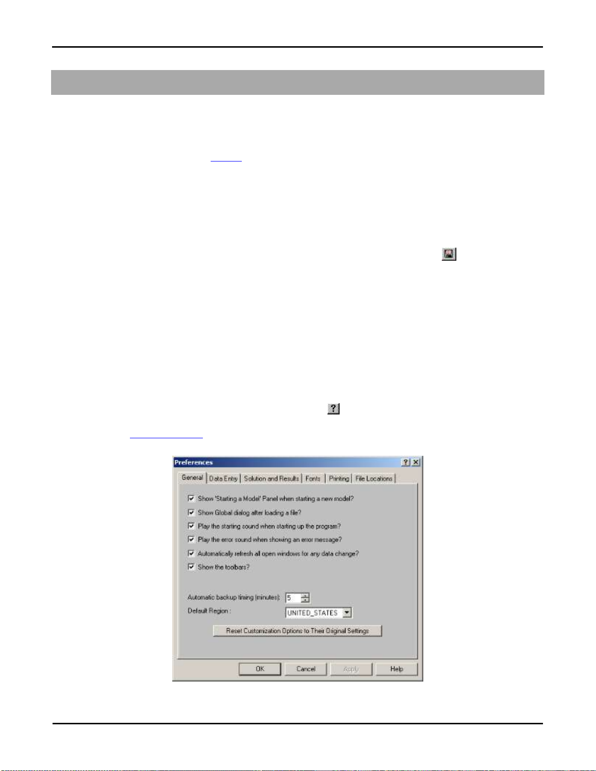
Customizing RISA
General Reference Manual
81
Customizing RISAFloor
You may customize many of the default parameters, design and analysis options in RISAFloor. In this way you can modify
the program so that it best suits you and your work processes. All customization may be defined or redefined at any time. The
Preferences option on the Tools Menu provides you control over the behavior of the software. The Save as Defaults feature
allows you to specify the default settings for new model files. These features are discussed below. Custom reports may also
be defined and saved for future use. See Printing to learn how to build a custom report.
Save as Defaults
You may use the Save as Defaults feature in the following dialog boxes by entering the default information in the dialog and
clicking the Save as Defaults button: Global Parameters, Units, and Drawing Grids. This will cause the program to use
these settings with any new files that are then created.
Many of the spreadsheets also provide the option to save the current data as the default and every subsequent new file will
already have that data. Simply enter the data you want then save it as the default by clicking on the button. This way the
office standards that you might use in most of your models are already entered and available in new models. This feature is
available in the following spreadsheets: Materials, Custom Wood Species, Design Rules, and Load Combinations.
Once you create a new file you may redefine any of the default data and settings for that particular file so the Save as
Defaults feature may be used to give you a good starting point for new files but won‟t hold you to those settings.
Preferences
Program options may be accessed by selecting Preferences from the Tools Menu and are divided into the five sections
described below. Many of the preferences themselves are self-explanatory.
General Preferences
The general preferences are straightforward. For help on an item click and then click that item. It may be a good idea to
disable the Automatically refresh… option when working with large files or slower computers. You may also set the
backup timing. See Automatic Backup to learn about the backup capabilities of RISAFloor. The Reset Customization
Options button will clear all of the preferences that you have set on any of the tabs.

Customizing RISA
82
RISAFloor v5.0
Show "Starting a Model" Panel when starting a new model – The New Model Dialog will be displayed when opening the
program or selecting 'New File' from the File Menu.
Show Global dialog after loading a file – Displays the Global Parameters settings automatically after loading a file.
Play the starting sound when starting up the program – A startup sound will be played when the program opens.
Play the error sound when showing error messages – An error sound will be played when an error is displayed.
Automatically refresh any open windows for any data change – Changes to the model will automatically be reflected in
all windows – spreadsheets and model views. For large models you may want to limit the number of open windows or disable
this feature altogether.
Show Toolbars – All toolbar commands may also be found in the menu system so if you want more work space you may
disable the toolbars.
Automatic backup timing – Automatic backup occurs at the specified interval. No backup occurs if the interval is set to
zero.
Reset Customization Options – Choose this to return to the program defaults.
Default Region – Choose the default region for your projects.
Data Entry Preferences
To use bigger or smaller fonts in the spreadsheets you may adjust the row heights. You may also specify the number of
decimal places that are displayed. The one exception is the Joint Coordinates. RISAFloor maintains the coordinates to 15
significant figures and the exact value is always displayed. You may use the Tools Menu to round off joint coordinates.
If you wish to use a prefix with your point, beam, and wall labels, such as “P” with points, you can specify the default prefix.
These prefixes may be changed as you build your model.
Row height for data spreadsheets – Sets the row height and font size for data spreadsheets.
Decimal places for data entry fields – Sets the number of decimal places to display in the data spreadsheets with a
maximum of four places.
Default prefix for POINT labels – Sets the default prefix to be used in point labels.
Default prefix for COLUMN labels – Sets the default prefix to be used in column member labels.
Default prefix for BEAM labels – Sets the default prefix to be used in beam labels.

Customizing RISA
General Reference Manual
83
Default prefix for PURLIN labels – Sets the default prefix to be used in purlin or 'in-fill beam' labels.
Default prefix for WALL PANEL labels – Sets the default prefix to be used in wall panel labels.
Solution and Results Preferences
RISAFloor can provide a warning when clearing results. To use bigger or smaller fonts in the results spreadsheets you may
adjust the row heights. You may also specify the number of decimal places that are displayed. The number of figures
displayed may not be the actual number. Behind the scenes RISAFloor maintains numbers to numerous decimal places.
Always warn before clearing results? – Verifies that results are to be cleared to edit the model.
Allow KL/r>200, l/r>300 for LRFD,CAN steel design? – Waives the slender check for slender members.
Row height for Results Browsers – Sets the row height and font size for results spreadsheets.
Decimal Places – Sets the number of decimal places to display in the results spreadsheets with a maximum of four places.
Saving Results – These options let you control what is done with the results when saving a file.
Font Preferences
The font preferences are straightforward. They can be used to adjust the fonts used by the spreadsheets, results browsers, and
graphics. The font changes will affect both the on-screen displayed data and the printed data. The exceptions to this are the
spreadsheet and browser fonts which may be changed for on-screen display but are hard-wired for printing purposes.

Customizing RISA
84
RISAFloor v5.0
If the font data has be set to some unusual settings, then the user can click the Reset All Fonts to Program Defaults button
to restore the fonts to what is normally expected for the RISA program.
Printing Preferences
The printing preferences are straightforward. For help on an item click and then click that item. See Printing for more
information.
Preferred orientation for graphics – Sets the default paper orientation for graphic printing.
Margins – Sets the default printing margins.
Report Preferences – Sets color or black and white options and header options.

Customizing RISA
General Reference Manual
85
File Preferences
The locations for data files, databases, temporary space, importing, and backing up may be specified separately by choosing
from the list.
Path and current setting – For each file type in the list the current setting is displayed. Click the drop down list to view
different file types. Click the browse button to choose a different location.

Decks and Slabs
86
General Reference Manual
Decks and Slabs
Decks may be defined for load attribution as well as composite beam design. Unbraced lengths for the top flanges of beams
may also be controlled through the deck properties. Loads may be associated with the deck, or defined with the applied loads.
Allowable span lengths can also be specified to avoid violating maximum span capabilities of the deck. Deck direction also
controls the span of wood structural panels for flexible diaphragms.
Note
The terms “deck” and “slab” are each appropriate for different types of floor construction. RISAFloor uses the term
“deck” when discussing properties in an area and the term “slab” when referring to outside edges and edges of
openings.
Slabs may be defined as rigid or flexible, and as such they determine the diaphragm behavior within themselves.
Slab edges and openings must be defined to establish the extents of the deck. Properties for the deck are defined in the Deck
Properties Spreadsheet. A default deck is listed for each floor on the Floors Spreadsheet. However, local deck systems
may be defined where deviation from the default deck system occurs.
Creating Slab Edges and Openings
To create slab edges or openings click on the Drawing Toolbar to open the Create Slab and Opening Perimeters
dialog. Enter the slab overhang distance and specify whether it is a slab perimeter or slab opening. For slab edges, select
whether you want the area bounded by the slab edge to be treated as a rigid or flexible diaphragm. For Slab perimeter, select
whether you want ALL selected Member/Walls to be considered for the slab perimeter or do you want to box or polygon the
slab perimeter, click Apply. For a Slab opening, select whether you want to click within or box the framed slab opening or
draw a polygon around the slab opening, click Apply. The new slab edge or opening will be shown on screen. For help on
an item, click and then click the item.

Decks and Slabs
General Reference Manual
87
To Create Slab Edges or Openings
1. If there is not a model view already open then click on the RISA Toolbar to open a new view and click to
turn on the Drawing Toolbar if it is not already displayed.
2. If you do not already have beams or walls modeled to support the slab edge you will need to create them first.
3. Click the button and set the edge distance. For help on an item, click and then click the item.
4. Click Apply. For slab edges:
If Consider ALL selected members was chosen then you should already see the slab perimeter.
If box or polygon was selected then start drawing by windowing a slab perimeter or by clicking with the left mouse
button outlining the perimeter.
For Slab Openings:
Start drawing by clicking within or windowing a framed slab opening or by clicking with the left mouse button
outlining the opening.
To stop drawing altogether click the right mouse button, or press the Esc key.
Note
Press CTRL-D to quickly recall any of the dialogs and make changes.
The coordinates of the closest grid or point to your cursor are displayed in the lower right hand corner.
You may undo any mistakes by clicking the Undo button.
Modifying Slab Edges and Openings
The graphical Modify Edge tool lets you modify the slab edges or openings that already exist in your model. You can redraw
slab edges, modify the overhang distance, modify edge intersections, delete an entire slab edge or opening, or change the
diaphragm type. You can modify slab edges or openings one at a time by selecting the Click The Edges or Click
Intersecting Points option and then click on the slab edges or points you wish to modify. You may also modify multiple
edges by selecting the slab edges first and then using the Apply To ALL or Merge ALL option. See Graphic Selection for
more on selecting.
To Modify Slab Edge and Openings
1. If there is not a model view already open then click on the RISA Toolbar to open a new view and click to
turn on the Drawing Toolbar if it is not already displayed.
2. Click the button and select the option you wish to use. For help on an item, click and then click the item.
3. To redraw an edge: Enter the Overhang Distance and click Apply. Select and redraw the edge you wish to modify.
4. To modify overhang distances: Enter the Overhang Distance and whether you want to Apply To All Selected or
Click the Edges to Modify. Click Apply.
5. To merge edges: You can choose Apply To All Selected to merge all the selected edges or Click the Edges to
Modify to merge edges one by one. Click Apply.
6. To delete an entire perimeter: Select this option and click Apply. You then click on the edge or opening perimeter
to be deleted.
Note

Decks and Slabs
88
RISAFloor v5.0
It may be necessary to merge edges prior to redrawing them.
You may undo any mistakes by clicking the Undo button.
To Modify Diaphragm Type
1. Click on the Modify Diaphragm Type radio button
2. Select whether you want to convert the diaphragm in question into a rigid or flexible diaphragm
3. Click Apply. The modification will be applied to all selected slab edges
Assigning Slab and Deck Properties
The default slab and deck properties and the deck angle are defined in the Floor Spreadsheet. If you have areas of your floor
that are oriented differently or have different deck properties, you will have to assign new local deck properties to these
areas.
To assign slab and deck properties click on the Drawing Toolbar to open the Deck Assignment dialog. Select a Deck
Type from the pull down list. See Deck Properties – General for more information on Decks or to add or remove decks from
the list.
Specify a Deck Direction by choosing Parallel to Horizontal, Parallel to Vertical or entering an angle that the span direction
makes with the horizontal axis.
You may apply the slab and deck properties by clicking within or boxing a deck area perimeter, by drawing a polygon around
the deck area perimeter, or by drawing point to point. For help on an item, click and then click the item.

Decks and Slabs
General Reference Manual
89
To Assign Slab and Deck Properties
1. If there is not a model view already open then click on the RISA Toolbar to open a new view and click to
turn on the Drawing Toolbar if it is not already displayed.
2. If you do not already have beams or walls supporting the area you will need to create them first.
3. Click the button and set the deck properties. For help on an item, click and then click the item.
4. Select how you would like to apply the local deck and click Apply. Start drawing the deck by clicking within or
boxing the area, drawing a polygon around the area perimeter, or clicking on grid or existing point locations with the
left mouse button.
5. To stop drawing altogether click the right mouse button, or press the Esc key.
Note
Except on slab edges, the local decks must be supported on all sides by beams or walls.
The default deck properties and the deck angle are defined in the Floor Spreadsheet. If these default properties are
sufficient, you do not need to draw in local deck assignments.
The coordinates of the closest grid or point to your cursor are displayed in the lower right hand corner.
Press CTRL-D to quickly recall the dialog and make changes.
You may undo any mistakes by clicking the Undo button.
The listed decks are presented in the same order in which they appear in the Deck Definitions spreadsheet.
Deck Properties – General
The Deck Properties Spreadsheet records the deck properties and may be accessed by selecting Deck Properties on the
Spreadsheets menu. The spreadsheet has three tabs: General, Composite and Loads.

Decks and Slabs
90
RISAFloor v5.0
The General tab holds the general data for the decks. The Composite tab adds data for the design of composite beams. The
Loads tab contains load information for the deck.
The entries for the General tab are explained below:
Label
A unique label may be assigned to all of the decks manually or automatically. You can then refer to the deck by its label.
You may relabel the deck at any time without affecting the application of the properties to the model.
Thickness
This defines the full thickness of a flat slab or the thickness of the concrete cover above the metal deck. A “0” indicates
metal deck and non-composite beams.
Concrete Strength, f’c
This is the strength of the concrete that will be used to design composite beams, including the determination of the stud
capacities.
Weight of Concrete
This is the weight of the concrete that will be used to design composite beams, including the determination of the stud
capacities. This will not be used to apply load to the model. All load information for the deck systems is defined on the
Loads tab.
Elastic Modulus
The modulus of elasticity for the concrete is used to design composite beams. If the cell is left blank, the value will be
calculated automatically from the f‟c value and weight above.
Max Span
Enter the maximum safe span allowed for the deck. If the span is exceeded, the location will be reported in the warning log.
Unbraced
The unbraced length that the deck provides to the top flange of the beams may be entered here. If left blank the deck is
assumed not to brace the beam top flange and the unbraced length is determined from the spacing of the framing, the full
length of the beam, and any values specified in the Beams Spreadsheet. See Unbraced Lengths for more on how the
unbraced length is determined.
Deck Properties – Composite
The data on the Composite tab adds many of the properties associated with composite beam design, including information
about the steel deck forming.

Decks and Slabs
General Reference Manual
91
Rib Height
Rib Height defines the total height of the deck ribs. Enter 0 for a flat slab.
Rib Widths
The Rib Widths define the top and bottom widths of the rib. If the Rib Height is set to 0 the Rib Width values are ignored.
Rib Pitch
Rib Pitch defines the spacing of the ribs. If the Rib Height is set to 0 the Rib Pitch value is ignored.
Stud Height
Stud Height defines the total height of the shear stud to be used for composite beam design calculations.
Stud Diameter
Stud Diameter defines the diameter of the shear stud.
Stud Fu
Stud Fu defines the Ultimate Tensile Strength of the shear stud
Shored
Check this box if the composite beams are shored during construction. Construction loads will ignored for shored composite
beams. Pre-composite loads like beam and deck self weight will be carried by the full composite section.

Decks and Slabs
92
RISAFloor v5.0
Deck Properties – Loads
The Loads tab holds all the load data for the slabs and decks. See Load Types – Deck Loads or Loads – Vertical for more
information on how loads are combined for solution.
Two Way
The decks can be specified as one-way or two-way to control the attribution of the applied loads. Check this box if you want
the area loads applied to the deck to be distributed based on two-way action. See Loads – Attribution for more information.
Self Weight
Self Weight is the weight of the deck system. This weight will be used as part of the pre-composite dead load (PreDL) and
also as part of the post-composite dead load (DL) when creating load combinations for solution.
Note:
The self-weight column here is what is used to assign camber. None of the load defined in the PreDL load category
will be considered when cambering members.
Construction Dead Load
You may define construction dead load that occurs during construction but is not part of the final load on the system. This
weight will be used as part of the pre-composite dead load (PreDL) but not included as part of the post-composite dead load
(DL) in the load combinations for solution.
Construction Live Load
You may define construction live load that occurs during construction but is not part of the final load on the system. This
weight will be used as part of the pre-composite live load (LLConst) but not included as part of the post-composite live load
(LL) in the load combinations for solution.
Slab Edge and Opening Perimeters
Slab edge perimeters must be specified to define the outer most extents of the floor deck or slab if automatic load attribution
or composite beam design is desired. The edge defines both the area available for loading and the available effective width
for composite beams. While load and deck areas may be defined beyond the slab edge, the portions outside the edge are
ignored at solution time.
Slab edges perimeters and slab openings can be generated automatically. See Creating Slab Edges and Openings to learn
how to draw and modify slab edges and openings.
Slab edges along with slab openings may also be used to define rigid diaphragms for lateral analysis in RISA-3D. See RISA-
3D Interaction for more information.
 Loading...