

Page 1
Page 2

The Designer
WOTS WOT - Instructions
Chris Foss outside his factory in 1990
Chris Foss
Chris Foss
The fascination of flight captured Chris's imagination early on in his life when he started building, from kits and plans,
simple free flight gliders and rubber powered models. By his early teens, Chris was already experimenting with his own
designs, several of which have been featured as constructional plans in various aeromodelling magazines.
It wasn't long before his fiercely competitive nature started to show itself, with Chris channelling his energies into competing
at national level with his own high performance free flight gliders.
In due course, Chris became tempted by the affordability of simple and fairly reliable radio control equipment, so by 1967
he had already designed, built and flown his first radio controlled glider. By 1976 his career in the architectural profession
came to an end when he decided to channel his knowledge and experience into a full time kit manufacturing business,
'Chris Foss Designs'. It soon developed into one of the UK's most successful and respected R/C model businesses, offering
a range of stylish and quality products.
With the advent of reliable and advanced radio control systems, Chris was able to expand his competition flying with
considerable success. His competition highlights include becoming 1977 British National Thermal Soaring Champion,
1986 British National Scale Champion, placing 4th at the 1986 World Scale Championships in Norway, placing 6th at the
1992 World Scale Championships in the USA, and winning both 1992 and 1993 'Radioglide' National Thermal Soaring
Championships.
In the late 70s Chris joined the local gliding club and achieved his ambition to actually fly himself! A few years later he
expanded into powered flight and qualified for his Private Pilot's Licence. By 2007 Chris had accumulated 2000 flying
hours in a wide variety of light aeroplanes, including a vintage Piper Cub, Jungmann aerobatic biplane, various glider tow
planes and his favourite, a Vans RV8 American aerobatic kitplane.
2
Page 3
WOTS WOT - Instructions
Introduction
Congratulations on your purchase of the WOTS WOT
ARTF - the first Almost Ready to Fly version of this classic
biplane. Designed to be quick to rig at the flying field (and
fit in most family cars fully assembled) it can be completed
in the minimum of time.
Before commencing construction, please ensure that you
read these instructions in their entirety.
Fitting the Ailerons and Assembling the Lower Wing
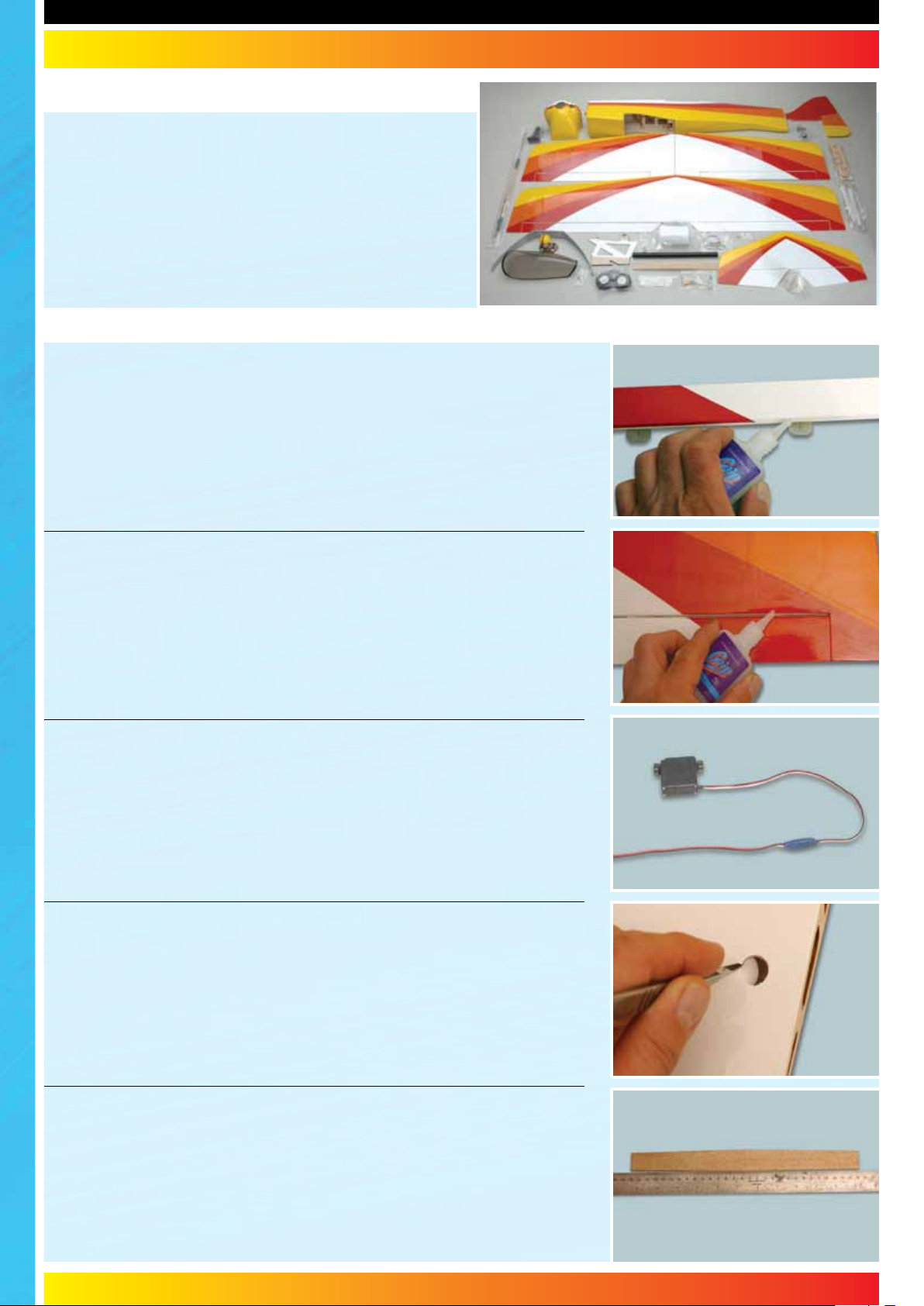
STEP 1
The wings and ailerons are supplied with the hinges loose fitted, ready for
installation. Remove both ailerons and ensure that the hinges are inserted midway in their slots. Using thin cyano, pour a couple of drops onto each hinge above and below - ensuring the glue soaks into the hinge and the surrounding
wood.
STEP 2
Carefully slide each aileron into position, ensuring a gap-free hinge line. Make
sure that each aileron lines up with the wing tips and that they are free to move
through their entire travel. Centre each aileron between the root and tip so that
there is an equal gap at both ends. Minimise any hinge gap, then carefully add
a couple of drops of thin cyano to the top and bottom of each hinge ensuring
that the glue does not run through the hinge line onto the bottom of the wing.
Turn the wing over and drop more cyano onto each hinge from the other side.
STEP 3
Prepare your aileron servos by connecting a suitable 300mm extension lead to
each. It is a good idea to use a lead-lock, a turn of insulation tape or heatshrink
tube over the joint for additional security.
STEP 4
Cut away the covering over the servo lead holes in the top of the wing panels,
and carefully pull the cotton thread already inside the wing through the hole
and retain with a short length of tape to stop the thread pulling back into the
wing.
STEP 5
Use a ruler as a straight edge to get the orientation of the wing joiner correct.
The rear of the joiner is straight (with all the taper being on the front) and the
upper surface is almost flat with the underside having all the dihedral.
3
Page 4
WOTS WOT - Instructions
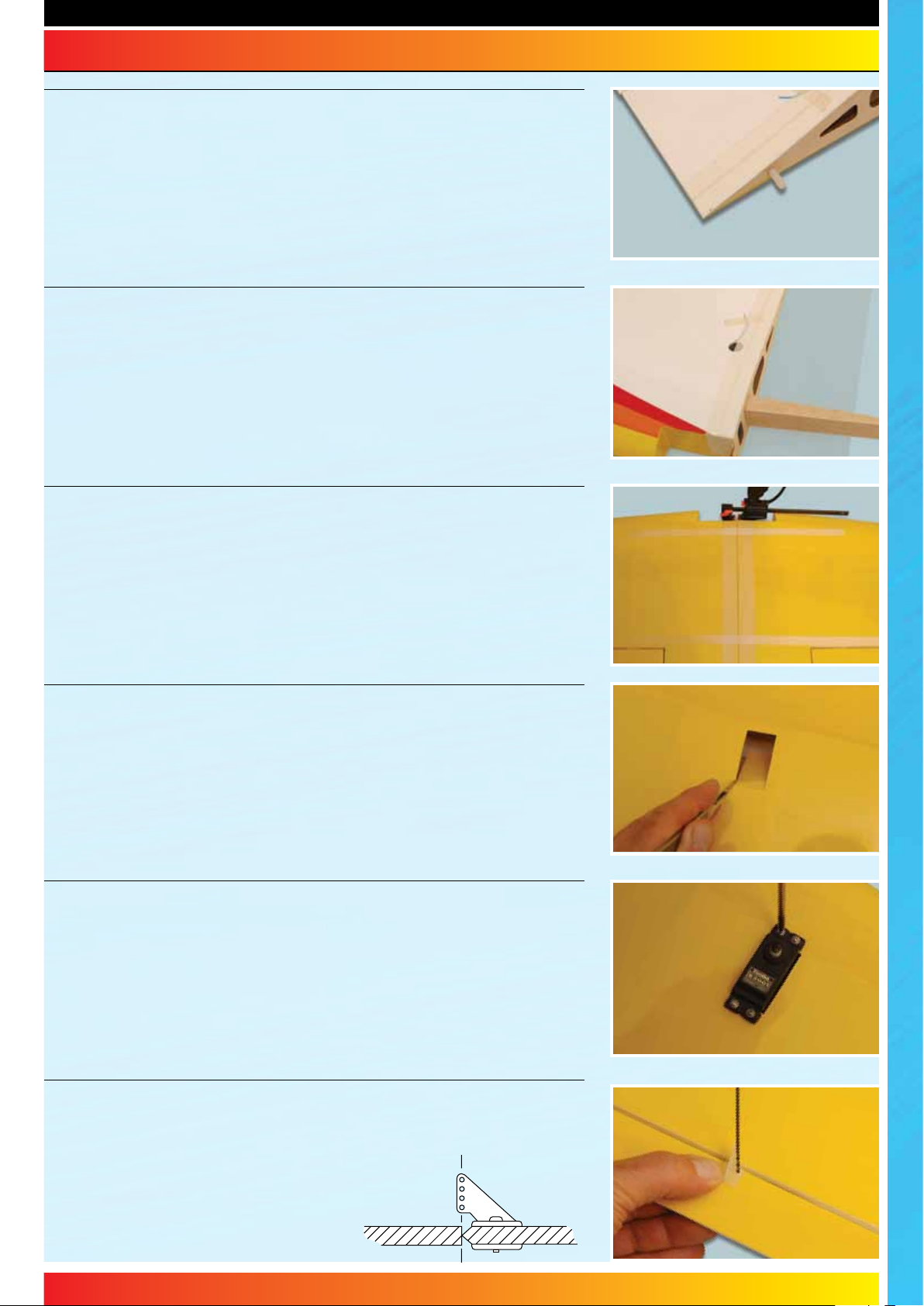
STEP 6
Locate the nylon dowel and epoxy into one wing panel to act as an alignment
peg.
STEP 7
Check the fit of the joiner in the two wing halves and once happy, mark the
centre-line of the joiner. Coat the inside of the corresponding slot in the wing
panel and one half of the brace with rapid setting epoxy. Ensure that adequate
epoxy is used to fully cover all surfaces. Insert the brace half-way into the wing
panel using the centre-line as a guide. Wipe off any excess epoxy.
STEP 8
Protect the covering with masking tape, then spread sufficient epoxy over
the opposite panel joiner slot, wing joiner and root rib. Bring the two panels
together ensuring the epoxy fills the join. Wipe off any excess that squeezes
out of the joint, then use tape and clamps to hold the panels together as the
adhesive cures.
STEP 9
Trim away the covering and check that your choice of servo fits the servo
apertures in the underside of the wing. Adjust the size of the mounting holes
with a sharp knife if required. Carefully tie each aileron servo's lead to the
length of cotton already in the wing panels. Carefully pull the leads through to
the centre of the wing and lift out the servo connectors. Retain the servo leads
with a short length of tape to stop them pulling back into the wing.
STEP 10
Screw the aileron servos in position using the mounting screws, rubber
grommets and ferrules supplied with your radio. Note that the output shaft end
of the servo is towards the front of the wing.
STEP 11
Locate the aileron control horns. They are screwed in position on the ailerons
in line with the aileron servo's output arm
(see the photo in step 16). Align the row of
holes in the horn with the hingeline. Mark
and pilot drill two mounting holes.
4
Page 5
WOTS WOT - Instructions
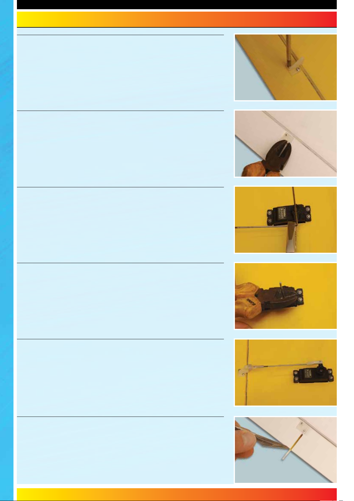
STEP 12
Now screw the horn to the aileron. The screws thread into the moulded horn
plate on the top surface of the wing.
STEP 13
Do not overtighten the control horn mounting screws - you don't want to crush
the aileron. Turn the model over and trim off any excess thread using side
cutters.
STEP 14
Use a small length of tape to hold each of the ailerons at their neutral position
while you complete the aileron linkages. Ensure that both aileron servos are
centred. Locate a threaded wire aileron pushrod and attach a nylon clevis to
the end. Connect it to the aileron horn and mark the position the control rod
passes over the servo’s output arm. Bend the pushrod up at 90° at this point.
STEP 15
Slide the aileron servo horn over the wire, re-fit to the servo and snap a moulded
keeper onto the pushrod to retain it. Trim off the excess pushrod wire using side
cutters. Repeat the procedure for the second aileron in exactly the same way.
STEP 16
Adjust the pushrods to ensure that the ailerons are centred with the aileron
servos at their neutral position. Test to ensure that both ailerons move freely
across their entire throw. Fit short lengths of fuel tube over each clevis to ensure
they cannot open under flight loads.
STEP 17
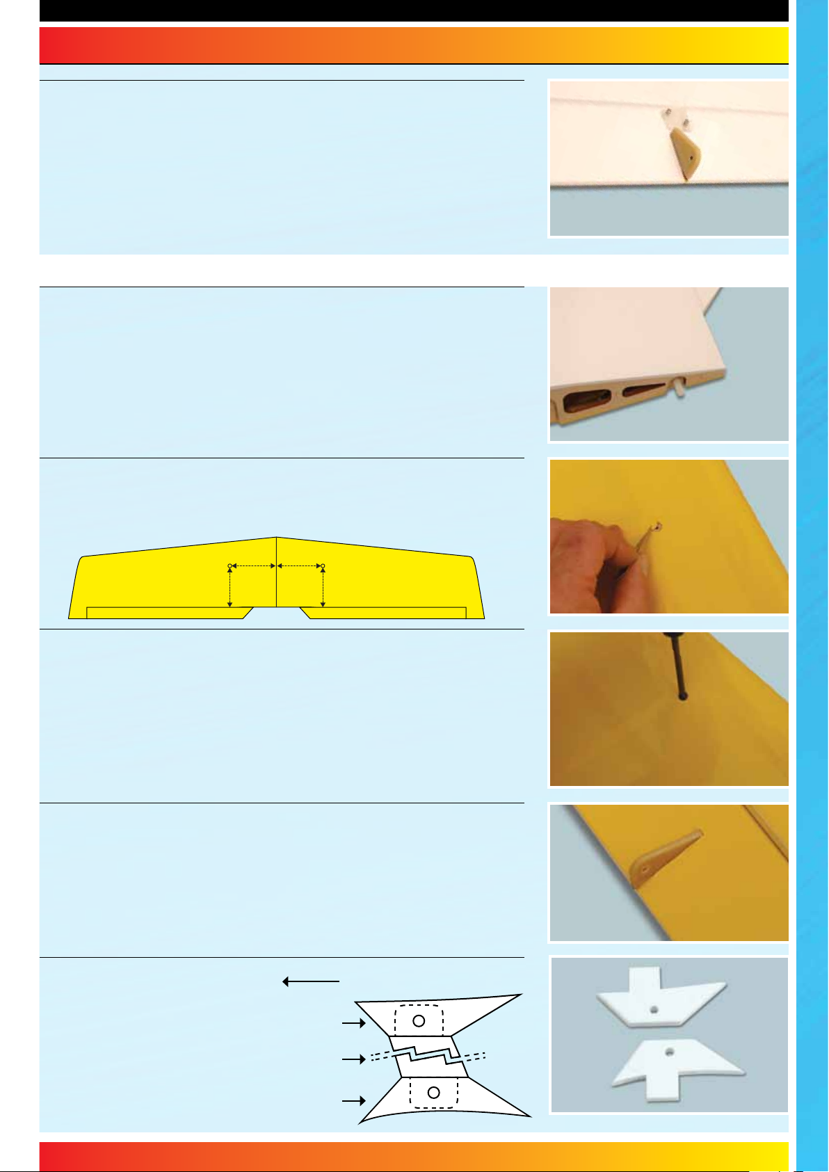
Locate the pre-cut slot for the aileron link horn. Carefully trim the film away
from the upper side of slot as shown. Make sure that you do not cut through
the film on the underside of the aileron.
5
Page 6
WOTS WOT - Instructions
STEP 18
Locate the fibreglass aileron link horns. Test fit the horn in its slot on the top
surface, noting that the hole is towards the rear of the aileron. Remove and
roughen the horn with coarse sandpaper. Epoxy in position with the base of the
horn flush with the bottom of the aileron.
Completing the Upper Wing
STEP 19
Hinge the ailerons using the same method as with the lower wing. Now locate
the nylon dowel and epoxy into one wing panel to act as an alignment peg.
STEP 20
Using a sharp knife, carefully trim away the covering to expose the holes in
the underside of the wing, for the screws that thread into the wing joiner tube.
145mm
140mm 140mm
145mm
STEP 21
The upper wing is joined with an aluminium wing joiner tube that is secured in
place with screws through these holes.
STEP 22
Using the same technique as the lower wing, roughen and glue the aileron
link horns in position on the underside of the ailerons. Note that the holes are
orientated towards the rear of the ailerons.
STEP 23
Locate the four plastic
moulded interplane strut
mounts, and identify the
top and bottom mounts.
The lower mount is more
curved than the upper.
Scuff the locating tabs for a
good key when gluing.
6
Wing Leading Edge
Upper Strut Mount
Strut
Lower Strut Mount
Page 7

WOTS WOT - Instructions
STEP 24
Place the strut mount in position on the wing. Check that you have the correct
mounts - the top and bottom are shaped differently to suit the wing curvature.
Also check that the mounts are the correct way round by temporarily dry
assembling the model with the struts in place to ensure that the are correctly
oorientated. Using a sharp knife, carefully trim around the mount's outline as
shown.
STEP 25
Remove the film as shown and glue the mount in position using 5 minute epoxy.
Repeat for the other side of the wing.
Fuselage
STEP 26
Using a sharp knife, carefully trim away the covering from the pre-cut cabane
mounting slot in the top of the fuselage with a sharp knife.
STEP 27
Use strips of masking tape to protect the covering film from excess epoxy.
STEP 28
Noting the orientation of the cabane, apply sufficient epoxy onto the plywood
cabane and slide it fully into position in the fuselage so that the tabs sit flush.
Wipe off any excess epoxy then remove the masking tape before the adhesive
cures.
Flush
Install up to this line.
Front of model
STEP 29
Use epoxy to fix the pilot figure in position. Use strips of masking tape to retain
the figure while the adhesive cures.
7
Page 8
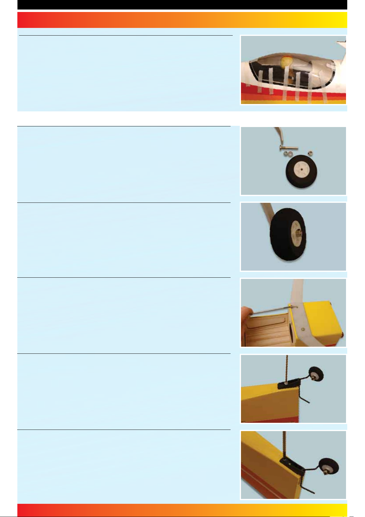
STEP 30
Using epoxy or canopy glue, fit the canopy using strips of tape to secure while
the adhesive cures. Ensure that the canopy is correctly centred front to rear
and left to right. Alternatively the canopy can be secured with small screws if
preferred.
Undercarriage
STEP 31
Locate the aluminium main undercarriage, wheels and wheel mounting
hardware (axles, collets, washers and nyloc nuts).
STEP 32
Insert the axle through the undercarriage leg, fit a washer and tighten the
nyloc nut. Slide a wheel over the axle and retain with collet using a little thread
locking compound on the grub screw. Repeat for the other wheel.
STEP 33
Install the main undercarriage using the two mounting screws and washers
supplied. For security, use thread lock compound on the screws.
STEP 34
Locate the pre-bent tailwheel assembly and fit the tailwheel using the supplied
collet. Hold the tailwheel bracket in position with the tailwheel wire inline with
the rear of the fuselage. Pilot drill holes for the retaining screws.
STEP 35
Screw the tailwheel bracket in position.
Now trim away the covering from the tailplane and fin mounting slots at the
rear of the fuselage.
8
Page 9
Tail and Fin
STEP 36
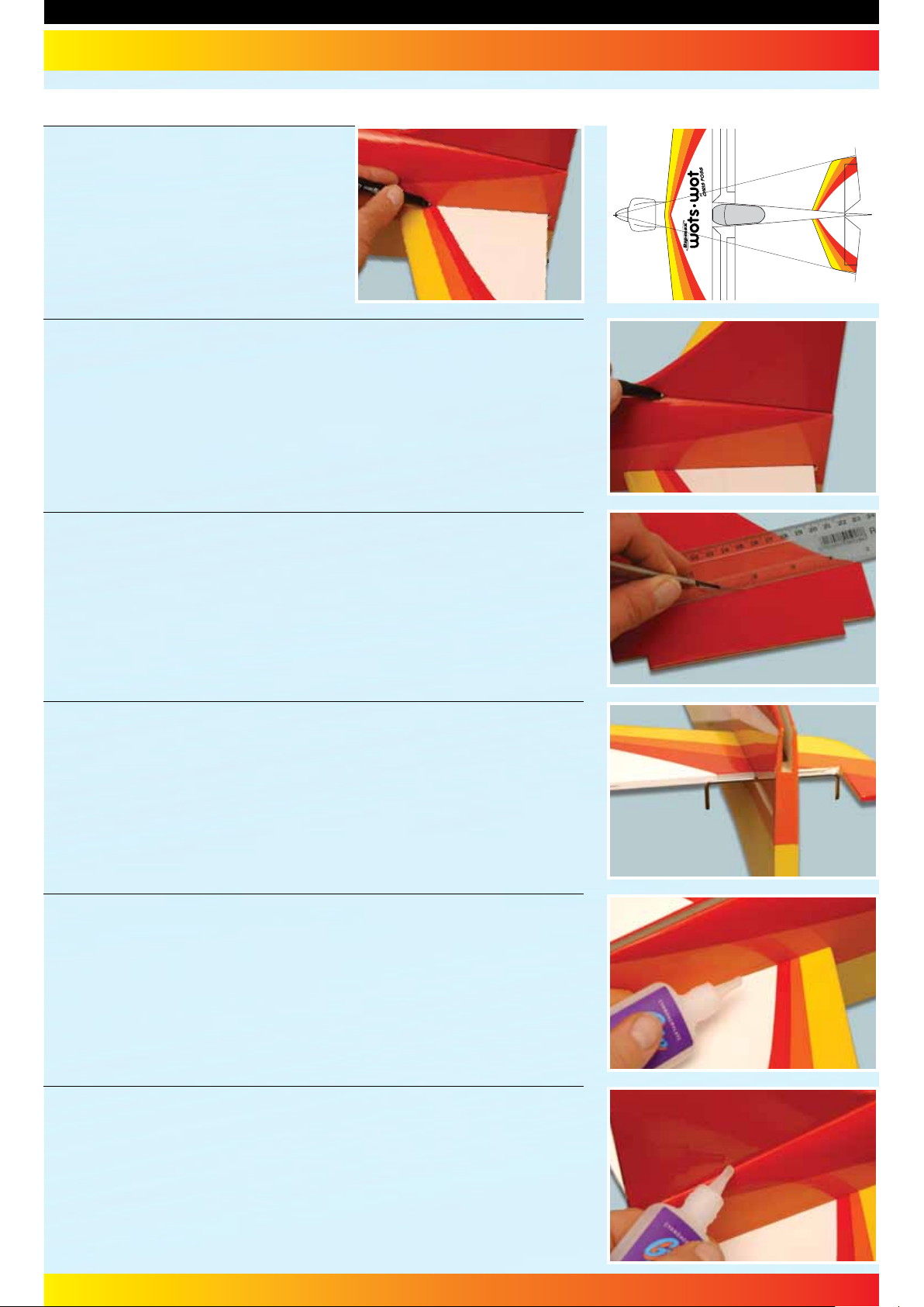
Slide the tailplane into its pre-cut slot in the
rear of the fuselage. Ensure that it is square
to the fuselage and centred in its slot
using a long ruler or string as shown in the
diagram on the right. Mark the tailplane
on the top & bottom where it enters the
fuselage using a soft, water-soluble pen.
STEP 37
Slide the fin into its pre-cut slot in the top of the fuselage. Ensure that it is
pushed down far enough to touch the top of the tailplane. Mark the fin on both
sides where it enters the fuselage using a soft, water-soluble pen.
STEP 38
Remove the tailplane and fin. Cut away the covering from both just inside the
marked lines to give a film-free surface for the glue to bond.
=
=
IMPORTANT: Ensure that only the film is cut - not into the wood - as this will
seriously weaken the structure.
STEP 39
Roughen the wire elevator joiner. Now loosely position the joiner at the rear of
the tailplane slot. Slide the tailplane into position. Do not omit this step as you
will not be able to install the joiner after the tailplane is glued in position.
STEP 40
Check that the tailplane is correctly aligned and square to the fuselage. Use
thin cyano to glue the tailplane into its slot, taking care not to allow glue to run
out of the joint.
STEP 41
Apply thick cyano or epoxy to the base of the fin then slide it into position.
Check that the fin is pushed down fully into its slot in the top of the fuselage
and ensure that it is perpendicular to the tailplane using a set square. Use thin
cyano to glue the fin into its slot, taking care not to allow glue to run out of the
joint.
9
Page 10

WOTS WOT - Instructions
STEP 42
Insert two hinges into the rudder and two more in each elevator half, ensuring
they are located mid-way in their slots. Using thin cyano, pour a couple of
drops onto each hinge - above and below - ensuring the glue soaks into the
hinge and the surrounding wood.
STEP 43
Protecting the rear of the tailplane with a strip of masking tape, apply epoxy
to each half of the wire elevator joiner and force it into the corresponding slots
and holes in the elevator halves. Slide the elevators into position ensuring that
the joiner and all four hinges enter their pre-cut slots in the tailplane.
STEP 44
Ensuring a gap-free hinge line and a 1mm gap between the elevator and tip,
hold the elevator halves level using strips of masking tape until the epoxy cures.
STEP 45
Now add a couple of drops of thin cyano to the top and bottom of each hinge.
Make sure that the glue does not run through the hinge line onto the bottom
of the tail.
STEP 46
Protecting the rear of the fuselage with a strip of masking tape, mix and apply
a small quantity of epoxy to the tailwheel wire. Force some into the slot and
hole in the rudder then slide the rudder in place making sure that both hinges
are located in their slots in the fin and that the tailwheel wire fits neatly into its
recess in the rudder. Wipe off any excess epoxy.
STEP 47
Ensure that the rudder is aligned to the top of the fin and there is free movement
left and right plus a gap-free hinge line. Now apply a couple of drops of thin
cyano to each side of each hinge taking care not to allow the adhesive to run
through the gap onto the other side of the model.
10
Page 11
WOTS WOT - Instructions
Radio Installation
STEP 48
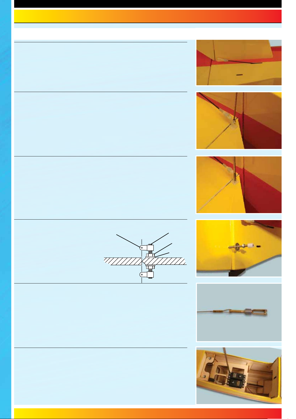
Locate the factory assembled elevator pushrod and slide it into position from
the radio bay and out through the exit slot. Screw a nylon clevis onto the rod
as shown.
STEP 49
Connect the clevis to a control horn and position the horn so that it is in line
with the hinge line. Holding the horn in position, pilot drill the elevator for the
mounting screws.
STEP 50
Screw the control horn to the underside of the elevator allowing the mounting
screws to thread into the moulded horn plate on the top surface of the elevator.
STEP 51
Locate the closed loop horn and
install it in the rudder in line with
the slots in the fuselage using the
nuts and washers as shown. Use a
threadlocking compound on the nuts
to ensure they do not loosen due to
engine vibration.
Control
Horn
Threaded
Rod
Nut
Washer
STEP 52
Cut the supplied single piece of closed loop wire into two equal lengths, then
fit a clevis onto the closed loop adaptor. Now loop one piece of the closed loop
wire through the adaptor and slip the brass tube supplied over the join. Crimp
firmly with pliers or side cutters and add a drop of cyano for increased security.
Repeat for the second length of wire.
STEP 53
Install your rudder and elevator servos in the pre-fitted servo tray as shown.
Note the orientation of the servo outputs. Note that there are two servo spacers
glued to the tray; these raise the height of the rudder servo for additional
clearance on the elevator servo.
11
Page 12
WOTS WOT - Instructions
Radio Installation
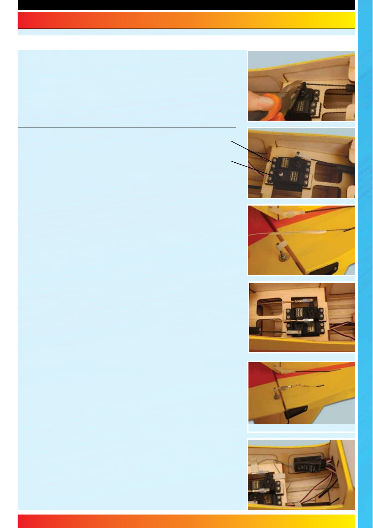
STEP 54
With the elevator and servo centred, mark the point that the pushrod passes
the servo output arm. Use a wrap of masking tape on the rod to make marking
it easier if required. Bend the pushrod up at 90° at this point.
STEP 55
Slip the bent pushrod through the servo horn and fit a moulded
swing-in keeper. Now trim off the excess length of wire, refit
the horn and test the operation of the elevator.
Elevator
Servo
Rudder
Servo
STEP 56
Slide a thin piece of wire forward through one of the closed loop exits in the
rear of the fuselage and feed it forward into the radio bay. Tape the closed loop
wire to this and use it to pull the closed loop wire out through the exit. Remove
the tape.
STEP 57
With the servo and rudder centred, connect the closed loop wires to the servo
horn as shown. .
STEP 58
Fit a clevis onto a closed loop adaptor and attach to the rudder's closed loop
horn. Now slip a length of the supplied brass tube over the closed loop wire,
pass the wire through the adaptor and back through the tube. Crimp the tube
carefully with pliers or side cutters and for additional security, add a drop of
cyano. Repeat for the second wire.
STEP 59
Install your receiver using foam backed double sided tape (if using an electric
powerplant) or use foam rubber if using an I/C engine.
12
Page 13
WOTS WOT - Instructions
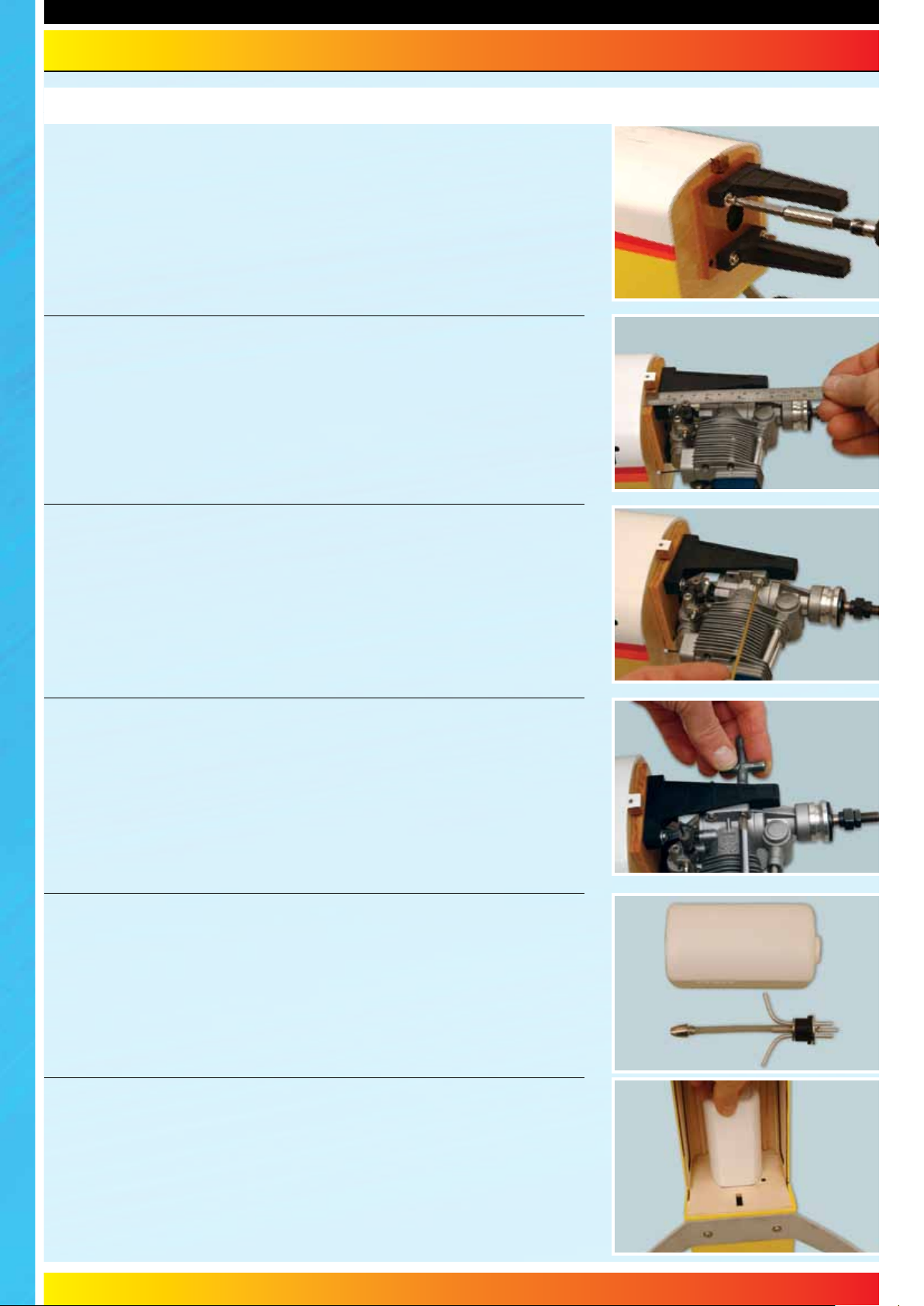
Four Stroke Engine Installation
STEP 60
Screw the engine mount onto the bulkhead as shown noting the orientation
of the mount. Use the supplied mounting screws and washers using thread
locking compound to secure. Note that the captive nuts have already been
factory installed in the bulkhead.
STEP 61
Place your engine on the mount. Adjust its position until the distance from the
front of the prop driver to the front of the main bulkhead (not plywood mount
plate) is 127mm.
STEP 62
Holding the engine steady, mark the position of the mounting holes on the
mount as shown. Remove the engine and drill four clearance holes through the
engine mounting beams to suit the bolts supplied.
STEP 63
Screw the engine to the mount using the four bolts, washers and nuts supplied.
Locate the throttle pushrod outer sleeve. Install the tube through the bulkhead
and secure with a drop of cyano. Form a 'Z' bend in the throttle pushrod. Fit to
the carburettor throttle lever and slide the pushrod into its outer. To do this, you
will need to temporarily remove the throttle lever from the carburettor.
STEP 64
Prepare the fuel tank for fitting by assembling the tank stopper with the feed,
vent and fuel pipes. Ensure the clunk tube length is cut to allow the clunk to
move around the tank without catching on the tank's base. Fit the assembled
tank bung and tighten the retaining screw noting that the tank is fitted on its
side. Take care not to over-tighten this screw. Test that the tank is leak-proof.
STEP 65
The tank is installed in its bay via the radio bay. Fit and identify your fuel tubes,
then feed the tank into position, drawing the fuel tubes out through the hole in
the centre of the firewall. If installing a receiver battery below the tank, do this
now before the tank is fitted. Ensure that the battery is wrapped in foam.
13
Page 14
WOTS WOT - Instructions
STEP 66
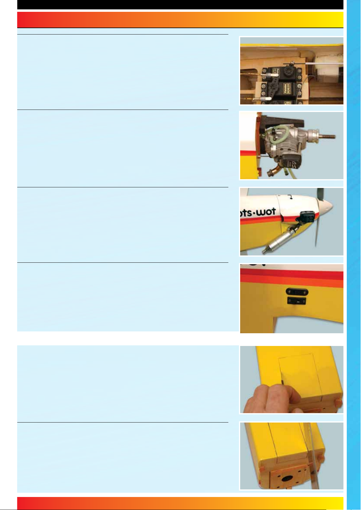
Install your throttle servo in the precut slot in the radio tray. Adjust the length
of the linkage so that mid-throttle stick position corresponds to the carburettor
being open 50%. Tighten the screw in the connector and adjust the high and
low throttle positions.
STEP 67
Connect the fuel line to the engine, pressure to the exhaust (if using exhaust
pressure) and block the vent line.
STEP 68
Trim the fibreglass cowl to clear the engine and silencer. The cowl should just
overlap the front of the fuselage. Carefully measure the positions of the cowl
mounting blocks and transfer these measurements onto the cowl. Pilot drill the
cowl and retain with three self tapping screws, one top centre and one each
side. Fit your propeller and spinner. The model is complete and ready for final
installation.
STEP 69
Cut a suitable aperture and fit your radio's switch (and charging socket if used)
to the left hand side of the fuselage.
Electric Motor Installation
STEP 70
Electric power requires a hatch to be cut in the bottom of the model for easy
access to your Li-Po. The hatch line is pre-cut by laser at the factory, leaving
tabs to hold it in place. The cut line can be seen through the film covering. We
suggest that you iron down the film around the hatch before it is removed to
ensure that it does not lift when cutting. Begin by cutting through the film where
marked using a sharp knife.
STEP 71
Use a razor saw to carefully remove the hatch in one piece.
14
Page 15
WOTS WOT - Instructions
STEP 72
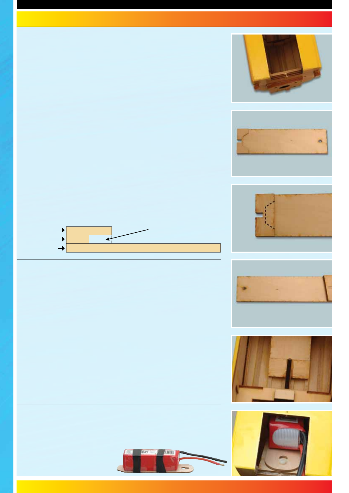
With the hatch removed, access to the Li-Po bay is gained.
STEP 73
Locate the fixed battery mount. Use a small amount of epoxy to glue the spacer
to the end opposite to the bolt hole.
STEP 74
Glue the cover plate over the spacer (shown dotted) to form a recess for the
tongue of the removable battery tray to locate.
Cover Plate
Spacer Plate
Battery Mount
Recess
STEP 75
Press in a captive nut from the underside of the fixed battery mounting plate as
shown and secure with 5 minute epoxy.
STEP 76
With the model upside down glue the fixed battery mounting plate in position.
The front should be flush with the bulkhead and the rear locates in the cabane
strut. Use five minute epoxy for this. Use the supplied piece of triangular balsa
under the front of the plate where it joins to the front former.
STEP 77
The 'tongue' on the removable tray locates in the ply pocket at the rear of the
fixed tray and a nylon bolt retains the plate. The removable plate has a keyhole
slot so that the retaining bolt needs to only be loosened to allow the plate to be
slid forward and removed to charge your Li-Po.
Attach your battery to the plate with
several layers of either electrical or
clear adhesive tape as shown.
15
Page 16
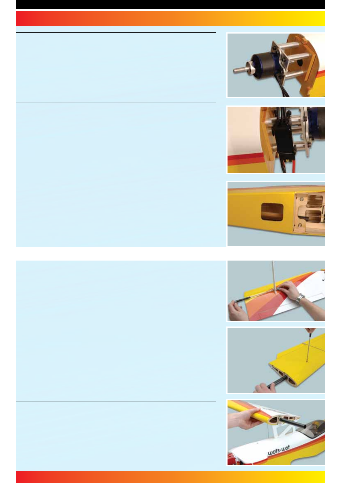
STEP 78
Install your choice of motor to the mounting plate using the screws, washers
and nyloc nuts supplied. Screw a threaded stud into the rear of each aluminium
stand-off. Now screw the stand-offs to the front former. Use pre-drilled hole
in each stand-off for a tommy bar to be used to tighten. Now fit the motor
mounting assembly to the stand-offs using the four screws and washers
supplied.
STEP 79
Mount your ESC as shown to ensure that it gets plenty of cooling air over it.
STEP 80
Use a sharp knife to open up the panel as shown on the underside of the model
to allow cooling air to exit.
Rigging for Flight
STEP 81
Rigging the Wots Wot is quick and easy if you follow this simple step-by-step
guide. Fit the interplane struts to the lower wing using the bolts, washers and
nyloc nuts supplied.
STEP 82
Slide the wing tube into the right-hand upper wing panel and tighten its
retaining screw. Connect a nylon clevis to the aileron linkage rod and attach to
the link horn on the upper aileron.
STEP 83
Slide the wing tube through the cabane strut holding the wing level.
16
Page 17
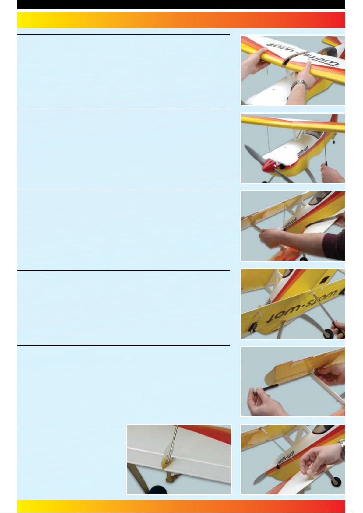
STEP 84
Now slide on the second wing panel ensuring it butts together to give a
gap-free join
STEP 85
Tighten the second wing tube retaining screw. Ensure that you do not
over-tighten the screws.
STEP 86
With the model standing on its nose, connect up the aileron extension leads
and locate the lower wing in its seat. Guide the two interplane struts into their
strut mounts in the underside of the upper wing.
STEP 87
Install and tighten the nylon wing retaining bolts.
STEP 88
Retain the interplane struts in the upper wing using the bolts, washers and
nyloc nuts supplied.
STEP 89
With the ailerons centred and the
surfaces level, complete the aileron
linkage rods by bending the rod at
90°, connecting to the link horn and
fitting a nylon keeper.
17
Page 18

WOTS WOT - Instructions
STEP 90
Congratulations - your Wots Wot is complete! Do not
omit the following steps - checking of the balance point
is critical.
Control Throws
For initial flights, we recommend the following control
throws - each measured at the widest point of the surface:
Elevator: 20mm up - 20mm down
20% exponential
Rudder: 60+mm left - 60+mm right
No exponential
Ailerons: 10mm up - 10mm down
(Measured on lower Ailerons)
30% exponential
Balancing the Wots Wot
The Centre of Gravity (C/G or Balance Point) should be
115mm (4-1/2") back from the leading edge of the upper
wing at the root. This should be measured with the fuel
tank empty or a Li-Po installed. Support the completed
model under the wing either side of the cabane strut at this
point and add weight or adjust the position of the radio or
flight battery in its bay as necessary to achieve a slightly
nose down attitude. A model that is not correctly balanced
will not perform as it should and, at worst, be unstable
or unflyable, leading to damage to the model or injury to
yourself or others. Do not miss out this step in completing
your Wots Wot!
Pre-Flight checks
• Completely charge your transmitter and receiver batteries
before flying.
• Carefully check your model over to ensure that all screws
are tight and everything is well bonded.
• Double-check the Wots Wot’s Centre of Gravity.
• Check the control surfaces for both the correct throw and
direction. Ensure that each surface moves freely, without
any binding.
• Check the receiver aerial is fully extended.
• Ensure the wing bolts are tight.
Always fly the Wots Wot in a safe location at a recognised club.
For further information on flying in the UK, please contact:
British Model Flying Association (BMFA)
Chacksfield House,
31 St Andrews Road,
Leicester. LE2 8RE.
Tel: (+44) 116 2440028 Fax: (+44) 116 2440645
www.bmfa.org
Flying the Wots Wot
The new Wots Wot biplane is a new addition to the Wot series of aircraft and it has (by general agreement) the best flying
characteristics of them all! With its sleek aerodynamic design and relatively large wing area, the Wots Wot has incredible
low speed handling; being able to fly at amazingly slow flying speeds. Yet open the throttle and the aerobatic performance
and precision is truly outstanding! With a .70 to .81 four stroke engine or electric power with suitable motor and 5 cell
battery pack, the Wots Wot offers a sparkling performance that will satisfy even the most demanding pilot. The model has
been optimised for rapid assembly/disassembly, requiring only 6 screws tightening and 2 clevises connected to be flight
ready... but it's compact enough to fit into most cars in one piece!
Spare Parts and Service
Spare parts are available for the Wots Wot ARTF from all Ripmax stocked model shops. In case of any difficulty, any product
queries, or to locate your local Ripmax stockist, please write to the address below or visit www.ripmax.com
Always Fly Responsibly and Safely
18
Page 19
WOTS WOT - Instructions
Notes:
19
Page 20

Distributed to your local model shop by: Ltd., 241 Green Street, Enfield, EN3 7SJ. United Kingdom
Made in China
 Loading...