

Page 1
Instruction Manual
Bauanleitung
A-CF011
Page 2
CONTENTS INHALT PAGE / SEITE
General Notices Wichtige Hinweise 2 / 3
Contents
Required to Complete
Inhalt
erforderliches Zubehör
4
4
Stages Schritte 5 - 15
Control Throws
Pre-Flight Checks
Spare Parts
Flying the Phase 5
Completed Model
Balancing
Specification: Wingspan: 1880mm (74”) Length: 1168mm (46”) Flying weight: 1270g (2.80Ibs)
Radio: 5-7 Channel* Servos: 6x Mini* *
Technische Daten: Spannweite: 1880mm Länge: 1168mm Fluggewicht: ca. 1270g
Fernsteuerung: 5...7-Kanal* Servos: 6x Mini* *
Ruderausschläge
Vorflug Checks
Ersatzteile
Den Phase 5 Fliegen
Fertiges Modell
Schwerpunkt
(Recommendation, not included)
16
16
16
17
17
17
(empfohlen aber nicht enthalten)
Page 3
INSTRUCTIONS / ANLEITUNG INSTRUCTIONS / ANLEITUNG
General Notices
Make sure you read this safety information and the instructions
before building your model. Follow exactly the recommended
procedures and settings given in the instructions.
If you are operating a radio-controlled model aircraft, helicopter,
car, multicopter or boat for the first time, we recommend that you
enlist the help of an experienced modeller to guide you. There
are also special clubs or modeling associations that offer training
services and assistance.
Safety Information
Radio-controlled models are not toys in the usual sense, and
young people under 14 years of age should not operate them
unless supervised by an experienced adult. It is advised not to
operate model multicopters, model helicopters, model aircraft or
model boats commercially without official permission. But you
are allowed to operate them for sports and recreational purposes,
sometimes authorisation from the local council may be required
to use a model in certain locations
The building and operating of models requires technical expertise,
manual skill, a careful attitude and use of safety-conscious
behavior. Errors, negligence and omissions in building or flying
these models can result in serious personal injury or damage
to property. Changes to the construction and deviating from the
operating manual will invalidate any warranty or liability claims.
Since the manufacturers and vendors of the equipment have
no means of checking that your models are built and operated
correctly, we explicitly bring your attention to these risks and deny
all further liability.
A properly constructed model may still be dangerous if
used incorrectly. Never reach into rotating propellers /
blades or other moving parts as this may cause serious
injuries. Note that motors, controllers and exhaust systems can
reach high temperatures during operation. Avoid all contact with
such parts.
The tools needed for assembly can also cause injuries. Even
metal or plastic parts which are broken or untrimmed can cause
injuries. Adhesives and paints may contain hazardous substances
like solvents etc. Please observe the manufacturer's information
and wear safety equipment (goggles, gloves etc.) when necessary.
Rubber parts (e.g. rubber bands) may become old and brittle and
fail. Such parts have to be checked before use.
Keep well clear of the electric motors and all moving
components when the battery is connected. Mistakes
happen and in spite of all safety precautions and there is
always a risk of damage and injury from parts such as propellers
or rotors. For example, by you may unintentionally move the
throttle stick on the transmitter during setup. Also ensure that
other hazards such as pets are not able to come in contact with
moving parts!
Never y a model aircraft, helicopter or multicopter at eye
level directly in line with other people/animals as this
will increase the risk of injury. Always keep yourself at a
safe distance from your model and pay particular attention while
take-off and landing for obstacles.
Observe the instructions of the battery and charger manufacturer.
Use only recommended battery chargers and recharge your battery
only until the specied charging time/level. Excess or incorrect
charging methods can lead to the battery exploding. Pay extra
attention to ensure correct polarity.
Protect your equipment from dust, dirt and moisture. Do not
expose the device to excessive heat, cold or vibration. The remote
control operation may be performed only within the specied
temperature range, avoid unusually hot/cold days.
Check your equipment regularly for damage and always replace
damaged components with original spare parts.
Don't re-use any equipment or devices which have been subject
to crash or water damage. Either return to the Service Department
for repair or replace. Hidden problems may occur after crash or
water damage which can lead to problems or total failure later in
operation.
Use only recommended components and accessories. On remote
control systems no changes may be made.
Routine Pre-Flight Checks
• Before switching on the receiver, ensure that the throttle
control on the transmitter is in the motor stop position.
• Always switch on the transmitter first and then the receiver.
• Always switch off the receiver first, then the transmitter.
• Before use perform a range test.
• Check if the correct model memory is selected.
• Perform a function test before each use, ensuring to check the
direction of travel, movement and all other functions including
mixing functions and default switch positions.
• Ensure all batteries are fully charged.
Operating the Model
• Never fly over or towards spectators or other pilots and
maintain a safe distance at all times.
• Never endanger people or animals!
• Never fly close to high-tension overhead cables or populated
areas.
• Do not operate your model in the vicinity of canals, locks or
open waterways.
• Do not operate your model from public roads, motorways, paths
and squares etc. Only at authorised spaces.
• Do not operate your models in thunderstorms as they could
interfere with the radio remote control systems.
Aerial Position
Never “point” the transmitter aerial straight at the model when
in operation. The signal generated by the transmitter is at its
weakest in an imaginary line extending straight from the aerial. It
is always best for the pilot to stand in a position where the long
side of the aerial points towards the model.
Insurance
Ground-based models are usually covered by standard personal
third-party insurance policies. For flying models additional
insurance is recommended. Check your insurance policy that you
are suitably covered and abode by its guidelines.
Liability Exclusion:
We have no control over the use of this product outside of the
parameters of the instructions, regarding methods of assembly/
installation, operation, misuse and poor maintenance of the
product or it’s components. Therefore, we assume no liability for
any loss, damage or costs arising from the improper use/operation.
Ripmax shall not be liable for any loss, consequential loss, damage
or expense arising from the improper use or operation in anyway.
In as far as legally permitted, compensation shall be limited to
the invoice value of the Ripmax products directly involved in the
damage-causing event. This does not affect your statutory rights.
Wichtige Hinweise
Lesen Sie vor dem Bau Ihres Modells unbedingt die
Sicherheitshinweise genau durch. Halten Sie sich stets an
die in den Anleitungen empfohlenen Vorgehensweisen und
Einstellungen.
Wenn Sie ferngesteuerte Modellfugzeuge, -hubschrauber, -autos
Multikopter oder -schiffe erstmalig betreiben, empfehlen wir
Ihnen, einen erfahrenen Modellpiloten um Hilfe zu bitten. Vereine
oder die Modellflug- oder Carverbände können diese vermitteln.
Sicherheitshinweise
Ferngesteuerte Modelle sind kein Spielzeug im üblichen Sinne
und dürfen von Jugendlichen unter 14 Jahren nur unter Aufsicht
von Erwachsenen eingesetzt und betrieben werden. ModellMulticopter, Modell-Hubschrauber, Flug- oder Schiffsmodelle
dürfen ohne entsprechende Genehmigung nicht gewerblich
eingesetzt werden, nur zum Zweck des Sports und der
Freizeitgestaltung. Einzelgenehmigungen erteilt das für das
Fluggebiet zuständige Regierungspräsidium. Der Bau und Betrieb
erfordert technisches Verständnis, handwerkliche Sorgfalt und
sicherheitsbewusstes Verhalten. Fehler oder Nachlässigkeiten
beim Bau, Fliegen oder Fahren können erhebliche Sach- oder
Personenschäden zur Folge haben. Änderungen des Aufbaus und
Nichteinhalten der Betriebsanleitung führen zum Verlust jeglicher
Gewährleistungs-oder Haftungsansprüche. Da Hersteller und
Verkäufer keinen Einfluss auf den ordnungsgemäßen Bau und
Betrieb der Modelle haben, wird ausdrücklich auf diese Gefahren
hingewiesen und jegliche Haftung ausgeschlossen.
Auch vom vorschriftsmäßig aufgebauten Modell können Gefahren
ausgehen. Greifen Sie niemals in sich drehende Luftschrauben/
Rotorblätter oder sonstige, offenliegende, sich bewegende Teile,
da ansonsten schwerwiegende Verletzungen entstehen können.
Beachten Sie, dass Motoren, Regler und Auspuffanlagen im Betrieb
hohe Temperaturen erreichen können. Vermeiden Sie unbedingt
eine Berührung solcher Teile.
Von den für den Zusammenbau notwendigen Werkzeugen
kann Verletzungsgefahr ausgehen. Ebenfalls besteht
Verletzungsgefahr bei abgebrochenen oder nicht entgrateten
Metall- oder Plastikteilen. Klebstoffe und Lacke können
gesundheitsgefährdende Substanzen wie Lösungsmittel usw.
enthalten. Beachten Sie die Herstellerhinweise und tragen Sie
ggfls. eine Schutzbrille. Gummiteile wie z. B. Gummiringe können
altern, spröde und unbrauchbar werden und müssen vor Gebrauch
getestet werden.
Bei Elektromotoren mit angeschlossenem Antriebs- oder
Empfängerakku niemals im Gefährdungsbereich von
Luftschrauben oder rotierenden Teilen aufhalten. Es
könnte trotz aller Sicherheitsvorkehrungen zum Anlaufen von
Propeller oder Rotoren kommen, z.B. durch unbeabsichtigtem
Verstellen des Leistungs/Gasknüppels am Fernsteuersender.
Achten Sie ebenfalls darauf, dass keine sonstigen Gegenstände
mit sich drehenden Teilen in Berührung kommen! Denken Sie
auch an Ihre Haustiere!
Fliegen Sie grundsätzlich, ob mit Modellflugzeugen-,
Hubschraubern- oder Multicoptern, nie in Augenhöhe
direkt auf sich oder andere Personen oder Tiere zu, es
besteht erhebliche Verletzungsgefahr. Halten auch Sie selber
immer einen ausreichenden Sicherheitsabstand zu Ihrem Modell.
Achten Sie auf freie Start- und Landeflächen.
Beachten Sie die Hinweise der Akku- und
Ladegerätehersteller.
Benutzen Sie nur empfohlene Ladegeräte und laden
Sie Ihre Akkus nur bis zur angegebenen Ladezeit. Über- oder
Falschladungen können zur Explosion der Akkus führen. Achten
Sie auf richtige Polung. Über- oder Falschladungen können zur
Explosion der Akkus führen. Achten Sie auf richtige Polung.
Schützen Sie Ihre Geräte vor Staub, Schmutz und Feuchtigkeit.
Setzen Sie die Geräte keiner übermäßigen Hitze, Kälte oder
Vibrationen aus. Der Fernsteuerbetrieb darf nur im angegebenen
Temperaturbereich durchgeführt werden. Überprüfen Sie Ihre
Geräte stets auf Beschädigungen und erneuern Sie defekte
Komponenten mit Original-Ersatzteilen. Durch Absturz
beschädigte oder nass gewordene Geräte, selbst wenn sie
wieder trocken sind, nicht mehr verwenden! Entweder im
Service überprüfen lassen oder ersetzen. Durch Nässe oder
Absturz können versteckte Fehler entstehen, welche nach kurzer
Betriebszeit zu einem Funktionsausfall führen. Es dürfen nur die
von uns empfohlenen Komponenten und Zubehörteile eingesetzt
werden. An Fernsteueranlagen dürfen keinerlei Veränderungen
vorgenommen werden.
Routineprüfungen vor dem Start
• Bevor Sie den Empfänger einschalten vergewissern Sie sich, dass
der Gasknüppel auf Stopp / Leerlauf steht.
•ImmerzuerstdenSender,danndenEmpfängereinschalten.
•ImmerzuerstdenEmpfänger,danndenSenderausschalten.
• Führen Sie vor dem Start einen Reichweitentest durch.
• Prüfen Sie, ob der korrekte Modellspeicher ausgewählt ist.
• Führen Sie einen Funktionstest durch. Prüfen Sie die
Laufrichtung und die Ausschläge aller Funktionen am Modell.
• Sind Mischfunktionen und Schalter richtig eingestellt?
• Ist der Ladezustand der Akkus ausreichend?
Modellbetrieb
• Überfliegen Sie niemals Zuschauer oder andere Piloten und
halten Sie genügend Sicherheitsabstand zu Ihrem Modell.
• Gefährden Sie niemals Menschen oder Tiere.
• Fliegen oder fahren Sie nie in der Nähe von
Hochspannungsleitungen oder Wohngebieten.
• Betreiben Sie Ihr Modell auch nicht in der Nähe von Schleusen
und öffentlichem Schiffsverkehr.
• Betreiben Sie Ihr Modell nicht auf öffentlichen Straßen,
Autobahnen, Wegen und Plätzen etc., sondern nur an
zugelassenen Orten.
•BeiGewitterndürfenFlugmodellegenerellnichtbetrieben
werden, Gewitterspannungen könnten die Funkfernsteuerung
stören.
Im Betrieb nicht mit der Senderantenne auf das Modell ‘zielen’.
In dieser Richtung hat der Sender die geringste Abstrahlung. Am
Besten ist die seitliche Stellung der Antenne zum Modell.
Versicherung
Bodengebundene Modelle sind üblicherweise in einer
Privathaftpflichtversicherung mitversichert. Für Flugmodelle ist
eine Zusatzversicherung oder Erweiterung erforderlich.
Überprüfen Sie Ihre Versicherungspolice und schließen sie ggf.
eine Versicherung ab.
Haftungsausschluss:
Ripmax Produkte sind häufig nur ein Teil einer ganzen
Funktionskette. Diese Funktionskette, wie auch die Einhaltung der
Montage und Betriebsanleitung als auch die Bedingungen und
Methoden bei Installation, Betrieb, Verwendung und Wartung der
Modellbaukomponenten können von Ripmax nicht überwacht
werden. Dafür ist immer der Pilot alleine verantwortlich. Daher
übernehmen wir keinerlei Haftung für Verluste, Schäden oder
Kosten, die sich aus fehlerhafter Verwendung und Betrieb ergeben
oder in irgendeiner Weise damit zusammenhängen. Soweit
gesetzlich zulässig ist die Verpflichtung zur Schadenersatzleistung,
gleich aus welchen Rechtsgründen, auf den Rechnungswert der an
dem schadensstiftenden Ereignis unmittelbar beteiligten RipmaxProdukte begrenzt. Dies gilt nicht, soweit nach zwingenden
gesetzlichen Vorschriften wegen Vorsatzes oder grober
Fahrlässigkeit unbeschränkt gehaftet werden muss.
232
3
Page 4
INSTRUCTIONS / ANLEITUNG INSTRUCTIONS / ANLEITUNG
Contents / Inhalt
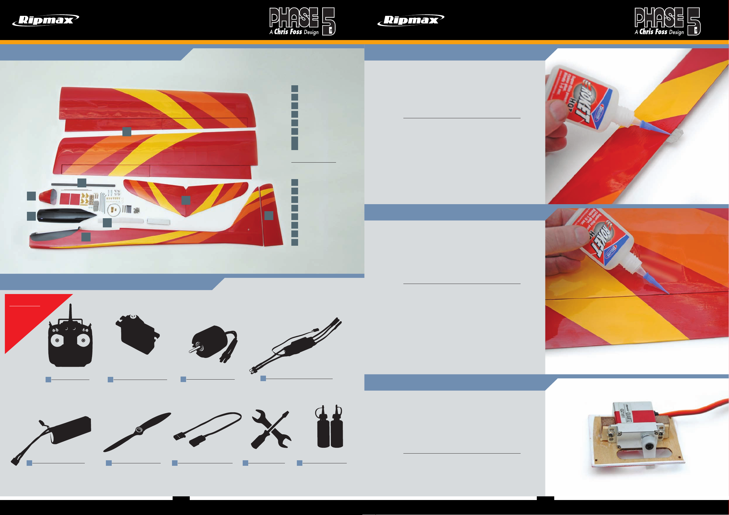
Take a moment to identify each of the parts supplied and read through these
instructions before commencing assembly.
1
7
6
3
5
8
2
Prüfen Sie die Teile vor dem Zusammenbau und lesen Sie die Bauanleitung.
Required to Complete / Erforderliches Zubehör
Recommended
Empfohlen
Servos: 2 x New Power 17g
Radio: 5 -7 channel
1
Fernsteuerung:
5...7 Kanal
Li-po Battery: 3S or 4S
2900mAh to 38 00mAh 30C
5
LiPo Akku: 3S oder 4S
2900mAh to 3800mAh 30C
(P-NEWXL17HMB) or
(P-NEWXLD17MB) and
4x Quartz QZ101 (P-QZ101)
2
Servos: 2 x New Power 17g
(P-NEWXL17HMB) oder
(P-NEWXLD17MB) und
4x Quartz QZ101 (P-QZ101)
Propeller: Folding 11x8˝
(E- R MXF1180Z P)
6
Propeller: K lapp 11x8˝
(E -RM X F1180 ZP)
EP Motor: Quantum II 36
(M - Q2 -36 )
3
EP Motor: Quantum II 36
(M-Q2-36)
Extension lead: 2x 500mm
(P-CF0500CSTD)
7
Verlängerungskabel:
2x 500 mm (P- CF05 00CSTD)
Parts List:
Teileliste:
4
Speed Controller: Quantum 60AMP
with 5V BEC (P-QESC60S)
4
Regler: Quantum 60A mit 5V BEC
(P-QESC60S)
Various hand tools
8
Diverse
Handwerkzeuge
1
Wings
2
Fuselage
3
Tailplane
4
Rudder
5
Canopy
6
Cowl
7
Wing Joines
8
Accessories
1
Tragfläche
2
Rumpf
3
Höhenleitwerk
4
Ruder
5
Kabinenhaube
6
Motorhaube
7
Steckungsrohr
8
Kleinteile
Cyano and Epoxy glue
9
Sekundenkleber und
Epoxy
Stage
Schritt
1
The wings and ailerons are supplied with the hinges loose fitted,
ready for installation. Remove both ailerons and ensure that the
hinges are inserted mid-way in their slots. Using thin cyano, pour
a drop onto each hinge – above and below – ensuring the glue
soaks into the hinge and surrounding wood on both ailerons.
(Top Tip) When using thin cyano (super glue) little and often is
better as this will stop any cyano runs on the airframe.
Die Flügel und die Querruder werden mit lose montierten
Scharnieren geliefert, und sind fertig für die Montage. Entfernen
Sie beide Querruder, und achten darauf, dass die Scharniere
mittig in den Schlitzen ausgerichtet sind. Verwenden Sie
dünnflüssigen Sekundenkleber. Kleben Sie mit ein paar Tropfen
Kleber jedes Scharnier, -oben und unten- in die Fläche, und
stellen Sie sicher, dass sich der Klebstoff mit dem Scharnier
und demumgebenden Holz verbunden hat. (Tipp) Wenn Sie
dünnflüssigen Sekundenkleber verwenden, ist dies von Vorteil.
Stage
Schritt
2
Carefully slide each aileron into position, ensuring a gap-free
hinge line. Make sure that each aileron lines up with the wing
tips and that they are free to move through their entire travel.
Minimise any hinge gap, then carefully add a couple of drops of
thin cyano to the top and bottom of each hinge ensuring that the
glue does not run through the hinge line onto the bottom of the
wing. Turn the wing over and drop more cyano onto each hinge
from the other side.
Schieben Sie jedes Querruder vorsichtig in Position, und stellen
Sie sicher, dass diese spaltfrei eingebaut sind. Vergewissern Sie
sich, dass jedes Querruder korrekt zwischen der Wurzel und der
Spitze zentriert wird, und dass sich diese zu jedem Zeitpunkt frei
bewegen können. Fügen Sie ein paar Tropfen Sekundenkleber
auf die Ober - und Unterseite der Scharniere, und achten Sie
dabei darauf, dass der Klebstoff nicht in den Spalt an der
Unterseite des Flügels läuft. Drehen Sie den Flügel anschließend
herum, und tropfen Sie nochmals Sekundenkleber auf diese
Seite der Scharniere.
Stage
Schritt
3
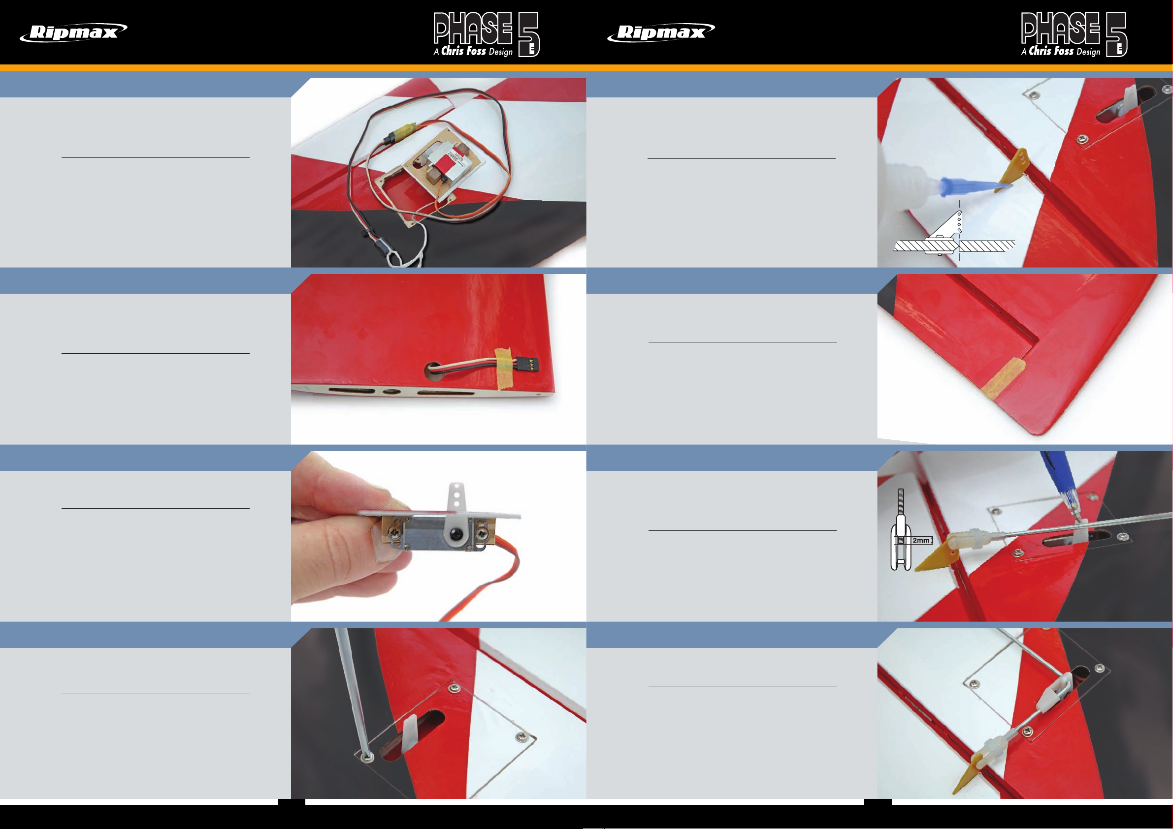
Remove the covering on the servo plate for the servo arm.
Install one of the aileron servos to the mounting plate, using the
wooden mounting blocks, making sure that the servo output arm
is central in the slot, as shown. This can be a bit tight in the servo
box in the wing, so take care to make sure that it is square on
the servo plate. Screw the aileron servo into position using the
mounting screws supplied with your servo. Note that the output
arm faces towards the rear of the wing and towards the wingtip.
Entfernen Sie die Folie über den Ausschnitten für die Servoarme.
Schrauben Sie die Querruderservos in Position, so dass die
Servohebel mittig im Schlitz sitzen. Beachten Sie dabei, dass die
Servohebel zur Flügelhinterseite und nach außen zeigen.
454
5
Page 5
INSTRUCTIONS / ANLEITUNG INSTRUCTIONS / ANLEITUNG
Stage
Schritt
Fit suitable 500mm extension lead to your aileron servo. It is a
good idea to use a lead-lock, a turn of insulation tape or heat
shrink tube over the joint for additional security. Carefully tie the
end of the servo lead to the length of string installed in the wing.
Bereiten Sie Ihre Querruder Servos vor, indem Sie ein passendes
500mm Verlängerungskabel mit jedem Servo verbinden. Es ist
eine gute Idee eine Steckersicherung, Isolierband oder einen
Schrumpfschlauch zur zusätzlichen Sicherung zu verwenden.
Befestigen Sie an jedem Querruder Servokabel den Faden, der
schon in der Flügelhälfte liegt.
Stage
Schritt
Carefully pull the lead through to the centre of the wing using
the string. Pull out the servo connector through the hole in the
bottom of the wing then retain the servo lead with a short length
of tape to stop the lead pulling back into the wing.
Ziehen Sie vorsichtig die Kabel durch die Mitte des Flügels,
unter Verwendung des Fadens. Heben Sie den Servo Stecker
aus dem Loch heraus, dann umwickeln Sie das Servokabel mit
etwas Klebeband, damit das Kabel nicht wieder in den Flügel
rutscht.
4
5
Stage
Schritt
Remove the film from the pre-cut slot in the aileron. Gently push
the aileron horn into the slot, making sure that the horn is at 90
degrees to the aileron, then carefully add a couple of drops of
thin cyano to the secure horn.
Drücken Sie vorsichtig das Querruderhorn in die vorgeschnittene
Öffnung im Querruder. Vergewissern Sie sich, dass das Horn 90°
zum Querruder steht, und verkleben dann das Horn mit ein paar
Tropfen dünnflüssigen Sekundenkleber.
Stage
Schritt
Use a small length of tape to hold the aileron in its neutral
position while you complete the aileron linkage. Ensure the
aileron servo is still centred.
Verwenden Sie etwas Klebeband, um jedes Querruder in
ihrer Neutralposition zu halten, während Sie die Querruder
Anlenkungen vervollständigen. Vergewissern Sie sich, dass
beide Querruder zentriert sind.
8
9
Stage
Schritt
Check that the servo arm is centred at 90 degrees to the servo
case with your radio switched on.
Mit eingeschaltetem Sender, überprüfen Sie ob der Servoarm im
90° Winkel zum Servogehäuse steht.
Stage
Schritt
Install the aileron servo hatch using 4 screws supplied taking
care to ensure it is fitted on the correct side and the colour
scheme matches.
Nun befestigen Sie den Servodeckel mit den vier mitgelieferten
Schrauben. Achten Sie darauf, dass dieser an der richtigen Seite
angebracht ist, und zum Farbschema passt.
6
7
Stage
Schritt
Locate a threaded wire aileron pushrod and attach a nylon clevis
to the end. Connect it to the aileron horn and mark the position
the control rod passes over the servo’s output arm. Bend the
pushrod up 90° at this point.
Nehmen Sie das Querrudergestänge mit Gewinde und befestigen
am Ende einen Kunststoff Gabelkopf. Verbinden Sie diesen mit
dem Ruderhorn und markieren Sie die Position des Servohebels.
Biegen Sie das Gestänge an diesem Punkt um 90°.
Stage
Schritt
Slide the aileron servo horn over the wire, refit to the servo and
snap a moulded keeper onto the pushrod to retain it as shown.
Schieben Sie das Querruder Servohorn über den Draht,
befestigen Sie dies wieder am Servo, und befestigen Sie einen
Sicherungsclip, wie gezeigt.
10
11
676
7
Page 6
INSTRUCTIONS / ANLEITUNG INSTRUCTIONS / ANLEITUNG
Stage
Schritt
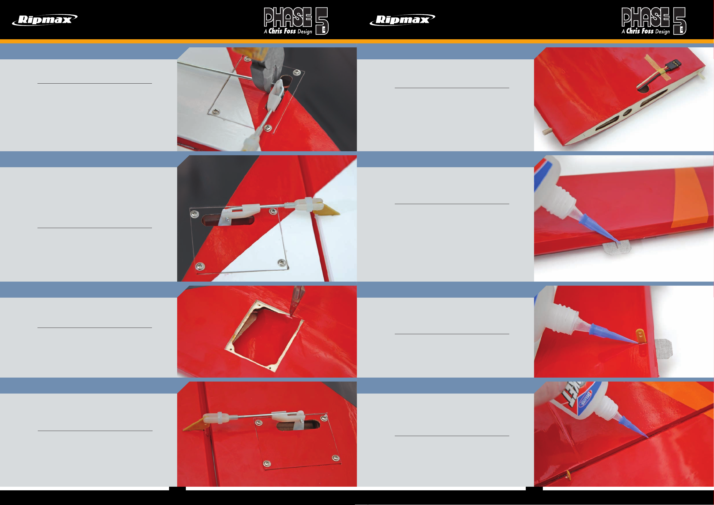
Trim off the excess pushrod wire using side cutters. Repeat the
procedure for the second aileron in exactly the same way.
Schneiden Sie das überschüssige Gestänge mit einem
Seitenschneider ab. Wiederholen Sie dieses Verfahren auch für
das zweite Querruder.
Stage
Schritt
Adjust the pushrods to ensure that the ailerons are centred with
the aileron servos at their neutral position. Test to ensure that
both ailerons move freely across their entire throw.
Note that we have fitted short lengths of fuel tube over the
clevis to ensure it cannot open under flight loads.
Repeat the procedure for the second wing in exactly the same
way as shown.
Stellen Sie die Gestänge so ein, dass die Querruder in
Neutralposition zentriert sind. Testen Sie die Querruder auf freie
Beweglichkeit über den kompletten Weg.
Sichern Sie die Gabelköpfe, wie gezeigt, mit einem kurzen
Stück Schlauch.
Wiederholen Sie dies auch für das zweite Querruder.
12
13
Stage
Schritt
Now locate the wing dowels and epoxy one of these into the front
of each wing at the leading edge and one plastic peg in the rear
of one wing panel as shown.
Kleben Sie die Verdrehsicherungen wie gezeigt mit Epoxy vorne
und hinten in die Flächen.
Stage
Schritt
Insert three hinges into the rudder, ensuring they are located
mid-way in their slots. Using thin cyano, pour a couple of drops
onto each hinge - both sides - ensuring the glue soaks into the
hinge and the surrounding wood.
Schieben Sie drei Scharniere bis zur Hälfte in das Ruder.
Verwenden Sie dünnflüssigen Sekundenkleber, und kleben
mit ein paar Tropfen Sekundenkleber jedes Scharnier – oben
und unten - in den Schlitz. Vergewissern Sie sich, dass sich
der Klebstoff mit dem Scharnier und dem umgebenden Holz
verbunden hat.
16
17
Stage
Schritt
Locate the flap servo apertures through the covering on the
underside of the wing. Carefully trim away the covering as
shown.
Schneiden Sie die vorsichtig die Folie für die Servoaufnahmen
an der Unterseite des Flügels aus, wie gezeigt.
Stage
Schritt
Repeat the same procedure for the flaps as you have done for
the ailerons. This may be different when setting up your servos,
depending whether you just have flaps only or you want to use a
mixing configuration like crow camber or full length ailerons.
Wiederholen Sie den Vorgang für die Klappen wie bei den
Querrudern. Dies kann bei der Einstellung der Servos
unterschiedlich sein, je nachdem, ob Sie nur Klappen haben
oder eine Mischkonfiguration wie Butterfly oder Querruder auf
voller Länge verwenden möchten.
14
15
Stage
Schritt
Gently push the rudder horn into the pre-cut slot in the rudder,
making sure that the horn is at 90 degrees to the surface and
centred then carefully add a couple of drops of thin cyano to
secure the horn.
Drücken Sie das Ruderhorn vorsichtig in den vorgestanzten
Schlitz im Ruder und stellen Sie sicher, dass sich das Horn 90
Grad zur Oberfläche und zentriert befindet Mit ein paar Tropfen
dünnflüssigem Sekundenkleber sichern Sie das Ruderhorn an
seinem Platz.
Stage
Schritt
Fit the rudder and ensure that it is aligned to the top of the fin
and there is free movement left and right plus a gap-free hinge
line. Now apply a couple of drops of thin cyano to each side of
each hinge taking care not to allow the adhesive to run through
the gap onto the other side of the model.
Stellen Sie sicher, dass das Ruder zur Oberseite der Finne
angeglichen ist, und sich dieses nach rechts und frei bewegen
kann, und dass es spaltfrei montiert wurde.Fügen Sie ein paar
Tropfen Sekundenkleber auf die andere Seite der Scharniere,
und achten Sie dabei darauf, dass der Klebstoff nicht durch den
Spalt auf die andere Seite des Modells läuft.
18
19
898
9
Page 7
INSTRUCTIONS / ANLEITUNG INSTRUCTIONS / ANLEITUNG
Stage
Schritt
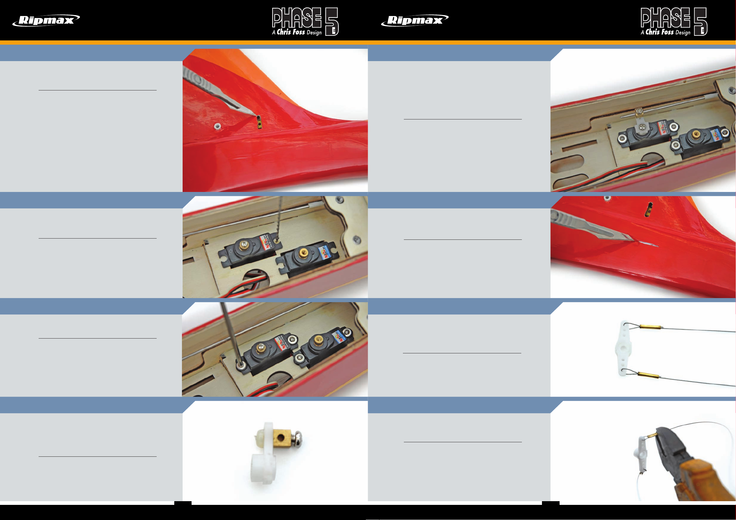
Locate the slots at the rear of the fuselage on the fin for the
tailplane front joiner and carefully trim the covering away as
shown.
Finden Sie die Einbauschlitze für das Höhenleitwerk an der
Rückseite des Rumpfes und schneiden vorsichtig die Folie ab.
Stage
Schritt
Install your elevator and rudder servos in the servo tray.
Note the orientation of the servo outputs. Pilot drill the tray
for your servo mounting screws.
20
21
Stage
Schritt
Slide the pushrod through the connector on the servo arms. With
the radio ‘ON’ and the servo in its neutral position, reposition
the servo arm and secure using the included screw fit and hold
the elevator at its neutral position while you tighten the elevator
connector. Do not overtighten the connector as you may strip the
thread, we recommend that you add thread lock to the screw.
Trim off the excess pushrod wire using side cutters.
Schieben Sie das Höhenrudergestänge durch den Anschluss
am Servoarm. Bei eingeschaltetem Sender und in der
Neutralstellung des Servos den Servoarm positionieren und
mit der im Lieferumfang enthaltenen Schraube befestigen.
Dabei das Höhenruder in seiner neutralen Position halten.
Ziehen Sie die Schraube nicht zu fest an, da Sie das Gewinde
beschädigen können. Wir empfehlen, die Schraube mit
einer Schraubensicherung zu versehen. Schneiden Sie den
überschüssigen Anlenkungsdraht mit einem Seitenschneider ab.
Stage
Schritt
Locate the rudder close loop exits on the left and right hand side
of the fuselage at the rear under the tailplane. Use a sharp knife
to carefully remove the covering.
24
25
Montieren Sie Ihre Höhenruder und Ruder Servos in
dem Ausschnitt auf dem Servoträger. Beachten Sie
den Servoausgang. Bohren Sie die Löcher für die
Servohalteschrauben vor.
Stage
Schritt
Fit the brass ferrules and rubber grommets supplied with your
servos, and then screw them in position as shown.
Befestigen Sie die Messinghülsen, und Gummiösen, die bei
Ihren Servos mitgeliefert wurden, dann schrauben Sie diese an
ihre Position, wie gezeigt.
Stage
Schritt
Locate the elevator pushrod connectors. Prepare the elevator
servo horns by assembling the pushrod connector as shown.
Slip the connector onto the horn and secure with the clip. This is
easier to do now than when the elevator horn is attached to the
servo.
Nehmen Sie die Gestängemitnehmer und befestigen je einen am
Servohorn für Höhen- und Seitenruder, wie gezeigt. Schieben
Sie den Mitnehmer auf das Horn und sichern diesen mit einem
Sicherungsklipp. Es ist einfacher, wenn Sie es jetzt machen, als
nach der Montage.
22
23
Suchen Sie die Ausgänge für die Anlenkungsdrähte auf der
linken und rechten Seite des Rumpfes hinten unter dem
Höhenleitwerk. Verwenden Sie ein scharfes Messer, um die
Abdeckungen vorsichtig zu entfernen.
Stage
Schritt
Cut the supplied single piece of closed loop wire into two equal
lengths, and then pass the closed loop wire through each side of
the servo arm and slip the brass tube supplied over the join as
shown.
Schneiden Sie den mitgelieferten Zug in zwei gleiche Längen.
Dann befestigen Sie einen Gabelkopf an dem Zug, indem
Sie diesen durch den Adapter schleifen, und schieben das
mitgelieferte Messingrohr über den Verbinder.
Stage
Schritt
Crimp carefully with pliers or side cutters. Repeat for the second
length of wire. For additional security, we recommend a drop of
cyano on each crimp.
Mit einer Zange oder Seitenschneider drücken Sie dieses vorsichtig zusammen. Wiederholen Sie dieses auch für die zweite
Hälfte des Zuges. Für mehr Sicherheit, empfehlen wir Ihnen
diese mit einigen Tropfen Sekundenkleber zu sichern.
26
27
101110
11
Page 8
INSTRUCTIONS / ANLEITUNG INSTRUCTIONS / ANLEITUNG
INSTRUCTIONS / ANLEITUNG
Stage
Schritt
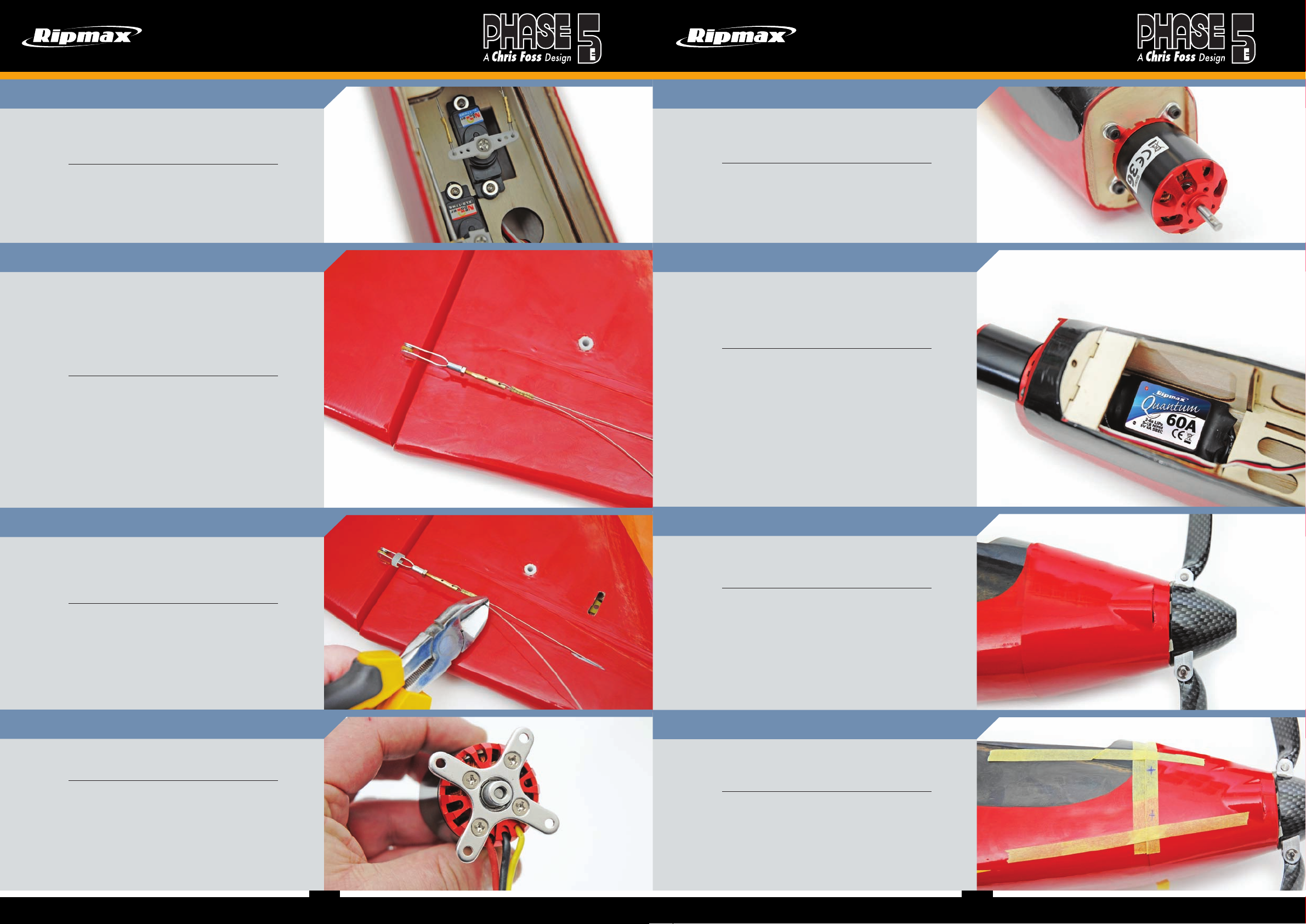
Feed the control wires down the tubes in the fuselage and with
the servo at its neutral position, reposition the servo arm and
secure using the included screw with your servo as shown.
Verbinden Sie die Züge mit dem Servohebel und führen Sie die
Züge durch die entsprechenden Rohre in den Rumpf.
Stage
Schritt
Fit a locking nut and clevis onto the closed loop adapter. Now
slip the brass tube supplied over the close loop wire and pass
the wire through the adapter, then slide the brass tube back over
the join. With the radio ‘ON’ and the servo rudder in their neutral
positions crimp carefully with pliers or side cutters. Repeat for
the second length of wire. For additional security,
we recommend a drop of cyano on each crimp.
Montieren Sie eine Sicherungsmutter und einen Gabelkopf auf
den Anlenkungsdraht. Schieben Sie vorher das mitgelieferte
Messingrohr über den Draht und führen Sie den Draht durch den
Adapter, dann schieben Sie das Messingrohr zurück über die
Verbindung. Nun das Messingrohr mit eingeschaltetem Sender
und dem Servo in Neutralposition vorsichtig mit Zange oder
Seitenschneider crimpen. Wiederholen Sie dies für die zweite
Seite. Für zusätzliche Sicherheit empfehlen wir einen Tropfen
Sekundenkleber auf jeder Crimpung.
28
29
Stage
Schritt
Fit the brushless motor using the screws supplied into the
captive nuts pre-fitted in the motor mount. Feed the motor wires
through the bulkhead.
Montieren Sie Ihren ausgewählten Brushless Aussenläufer
Motor, und verwenden dafür die Schrauben, die mit den
montierten Muttern am Motorträger mitgeliefert wurden.
Stage
Schritt
Connect your ESC to the motor and mount to the bottom of the
fuselage infront of the battery tray using hook & loop tape.
Take care to keep the ESC open to airflow and never pack in
foam. This is a good time to check the motor direction and swap
two wires if needed.
Verbinden Sie den Regler mit dem Motor und befestigen Sie
diesen unterhalb des Akkuträgers mit Klettband am Rumpf.
Achten Sie auf offenen Luftschacht und packen Sie den Regler
nicht in Schaumstoff o.ä. Testen Sie nun die Motorlaufrichtung
und tauschen Sie ggf. zwei Motorkabel, um die Richtung zu
ändern.
32
33
Stage
Schritt
Trim off the excess closed loop wire using side cutters. Adjust
the adapter at the rudder horn to achieve the desired cable
tension. Ensure the tube retainers are fitted and the nuts are
tightly secured.
Schneiden Sie den überschüssigen Draht mit einem
Seitenschneider ab. Stellen Sie den Adapter am Ruderhorn ein,
um die gewünschte Kabelspannung zu erreichen. Stellen Sie
sicher, dass die Kontermuttern fest angezogen sind.
Stage
Schritt
Bolt your choice of brushless outrunner electric motor to the
motor mounting plate supplied with your motor.
Schrauben Sie Ihren Elektromotor am Motorträger fest.
30
31
Stage
Schritt
To set the cowl/spinner clearance, attach some foam tape to
the back of the spinner to act as a spacer. Position the cowl and
spinner to get the clearance correct.
Zum Einstellen des Abstandes der Motorhaube und des Spinners
befestigen Sie einige Schaumstoffbänder an der Rückseite
der Spinnerplatte. Diese dienen so als Abstandshalter für das
richtige Spaltmaß. Diese bitte am Ende wieder entfernen.
Stage
Schritt
Use masking tape to position and mark screw points. Drill and
screw the cowling in position using two screws on each side.
When in position remove spacers and attach the spinner.
Bohren und befestigen Sie die Motorhaube mit zwei Schrauben
auf jeder Seite. Nutzen Sie Maskierungsband, um die Bohrungen
anzuzeichnen. Montieren Sie anschließend den Spinner.
34
35
12
13
13
Page 9
INSTRUCTIONS / ANLEITUNG INSTRUCTIONS / ANLEITUNG
Stage
Schritt
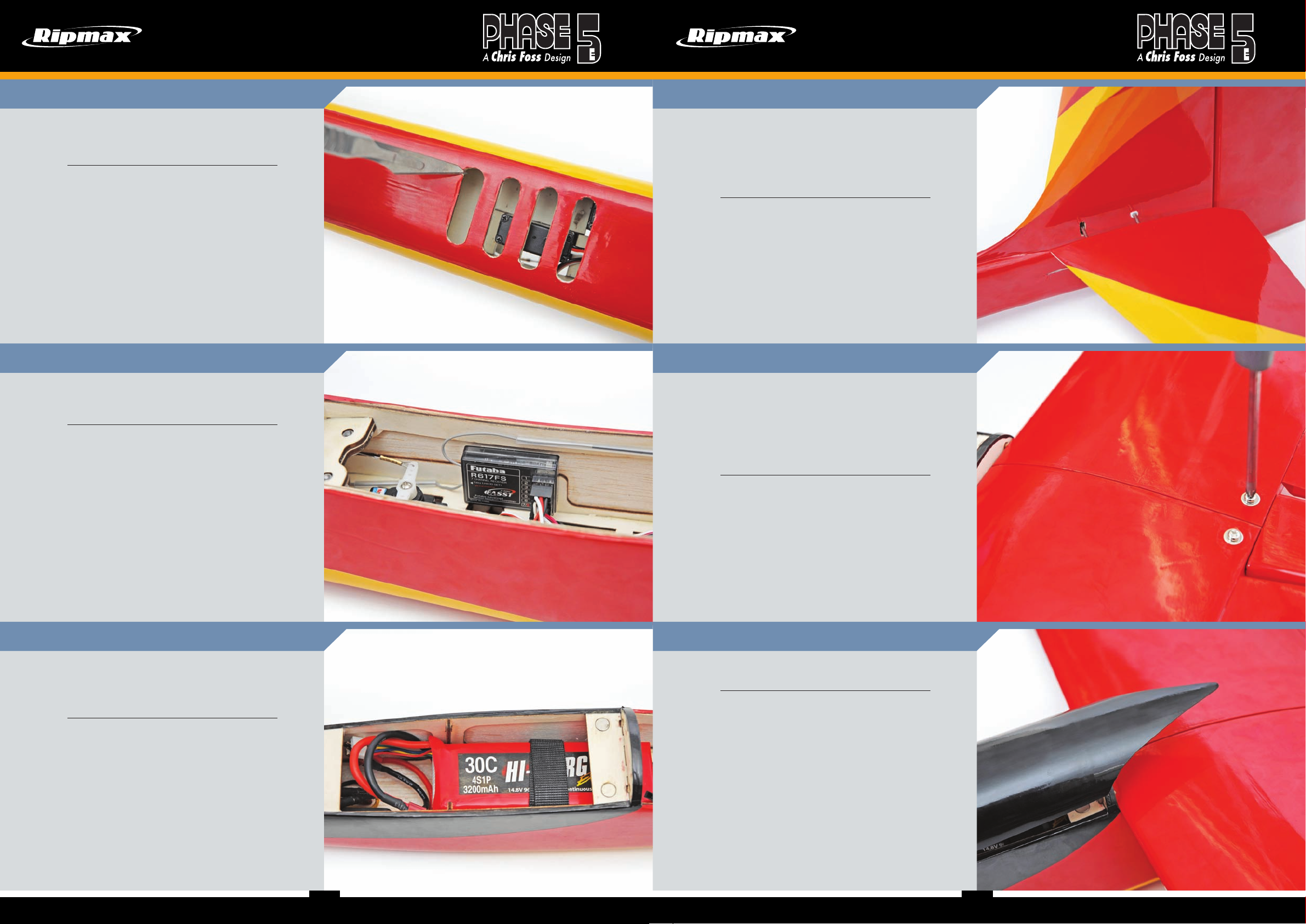
There are a series of cooling holes in the underside of the
fuselage. Using a knife, remove the film from these openings to
aid airflow through the cowling, over the battery and out again.
Auf der Unterseite des Rumpfes befinden sich einige
Entlüftungsöffnungen. Entfernen Sie die Folie, sodass die
Kühlluft durch die Motorhaube über den Akku und wieder aus
dem Rumpf strömen kann.
Stage
Schritt
Plug in your receiver and mount either in foam packing or using
foam tape. Secure the aerials and add extensions and/or Y-leads
for the ailerons and flaps.
Schließen Sie Ihren Empfänger an, und befestigen diesen
eingewickelt in Schaumstoff, oder Schaumstoffband. Sichern Sie
die Antennen und befestigen ein Y-Verlängerungskabel für die
Querruder.
36
37
Stage
Schritt
Locate the two tailplane halves and joining rods, then push the
larger rod into the rear tube of one tailplane half and the smaller
one in the front. Now slide the tailplane half through the fuselage
and side the other tailplane on. This should be a tight fit, if not
you can bow the front wire a small amount and then refit the
tailplane, this should make a tighter fit.
Nehmen Sie die beiden Höhenleitwerkhälften und die
Verbindungsstangen, dann schieben Sie die größere Stange in
das hintere Rohr einer Höhenleitwerkhälfte und die kleinere in
die vordere. Schieben Sie nun die Stange halb durch den Rumpf
und seitlich das andere Höhenleitwerk auf.
Stage
Schritt
Remove the covering on the wings top and bottom at the holes
for the mounting bolts. Insert the carbon spar and slide the
wings together making sure the rear peg lines up. Then connect
your servo leads. Line up the front wing dowels with the holes
in the fuselage and gently push the wing into the fuselage. Bolt
the wing to the fuselage at the rear with the bolts supplied. Take
care not to trap the servo leads when securing your wing.
Entfernen Sie die Abdeckung an den Flügeln oben und unten
an den Löchern für die Befestigungsschrauben. Setzen Sie
den Carbonholm ein und schieben Sie die Flügel zusammen,
um sicherzustellen, dass der hintere Stift ausgerichtet ist.
Dann verbinden Sie Ihre Servokabel. Richten Sie die vorderen
Flügelstifte mit den Löchern im Rumpf aus und schieben Sie
den Flügel vorsichtig in den Rumpf. Schrauben Sie den Flügel
mit den mitgelieferten Schrauben hinten am Rumpf fest. Achten
Sie darauf, die Servokabel beim Befestigen des Flügels nicht zu
blockieren.
39
40
Stage
Schritt
The battery is retained using a hook & loop strap. Each strap is
made by overlapping one end of each type by 30mm and running
some thin cyano in the joint. Then feed the straps through the
slots ready to secure the battery.
Befestigen Sie den Akku sorgfältig mit Klettband, wie rechts
gezeigt. Die Überlappung sollte min. 3cm betragen. Sichern Sie
das Band mit Sekundenkleber am Holzspant.
38
141514
Stage
Schritt
The canopy slots into place at the front with a locating peg and
two magnets retain the canopy at the rear.
Die Kabinenhaube wird mit dem Zentrierstift an der Vorderseite
im Rumpf befestigt und zwei Magnete halten die Haube an der
Rückseite fest.
41
15
Page 10
INSTRUCTIONS / ANLEITUNG INSTRUCTIONS / ANLEITUNG
Control Throws / Ruderausschläge
For initial flights, we recommend the following control throws each measured at the widest point of the surface.
With experience these rates can be increased for high
performance aerobatics.
Low Rat e Expo High R ate Expo
Elevator: 8mm - Up /Down 10% 12mm - Up /Down 20%
Rudder: 25mm - Left /Right 15% 40mm - Left /Right 25%
Ailerons: 20m m - Up 10% 30mm - Up 20%
15mm - D own 10% 20mm - Do wn 20%
Flaps: 30mm - Down (6mm Down Elevator mix at full Flap)
Crow: Ailerons Up 20mm & Flaps Down 20mm
Für erste Flüge empfehlen wir die folgenden Ruderausschläge
(gemessen am äußersten Ende der Ruder). Mit entsprechnder
Erfahrung können diese Ruderausschläge vergrößert werden.
niedr iger W ert : Exp o: hoher Wert: Expo:
Höhe: 8mm - Oben /Unten 10% 12mm - Oben /Unten 20%
Seite: 25mm - Links /Recht 15% 40mm - Links /Recht 25%
Quer : 20mm - Oben 10% 30mm - Oben 20%
15mm - Unten 10% 20mm - Unten 20%
Klappen: 30mm -
Butterfly: Quer 20mm Oben - Klappen: 20mm Unten
nach unten (6mm Höhenruder nach unten dazu mischen)
Pre-Flight Checks / Vorflug Checks
Flying the Phase 5 / Den Phase 5 Fliegen
The Phase 5 is a versatile sport glider with both impressive soaring abilities and aerobatic agility. The all moving tail is very powerful so
please pay special attention to the recommended CG setting and movements. Using the flaps will cause the model to dramatically pitch
up, so a down elevator mix is required, please don’t skip this! When the flaps are down always have the mix on, even if you are using crow
braking (ailerons up and flaps down). The stall is extremely forgiving, only slightly dropping a wing and nodding the nose when airspeed is
too low, practice this at height and you will see what we mean. We highly recommend that you set your ESC to engage the ‘propeller brake’
mode, this will stop the propeller from spinning while gliding and allow it to fold for minimal drag.
Der Phase 5 E ist ein vielseitiger Sportsegler mit beeindruckender Segelleistung und Kunstflugfähigkeit. Das Pendel-Leitwerk ist sehr
kraftvoll, bitte achten Sie daher besonders auf die empfohlenen Schwerpunkteinstellungen und Ruderausschläge. Durch die Verwendung der
Klappen wird das Modell sehr stark steigen, sodass ein Höhenruder-Mix erforderlich ist. Bitte übersehen Sie dies nicht! Wenn die Klappen
unten sind, muss die Mischung immer eingeschaltet sein, auch wenn Sie Butterfly verwenden (Querruder hoch und Klappen runter). Zu niedrige Fluggeschwindigkeiten sind extrem fehlerverzeihend. Ein Flügel und die Nase werden leicht sinken. Üben Sie das in sicherer Höhe und
sie werden sehen, was wir meinen. Wir empfehlen dringend, dass Sie Ihren Regler so einstellen, dass die Bremse aktiviert ist. Dadurch wird
erreicht, dass sich der Propeller nicht mehr dreht, während das Modell gleitet und dass der Propeller einklappen kann.
Completed Model / Fertiges Modell
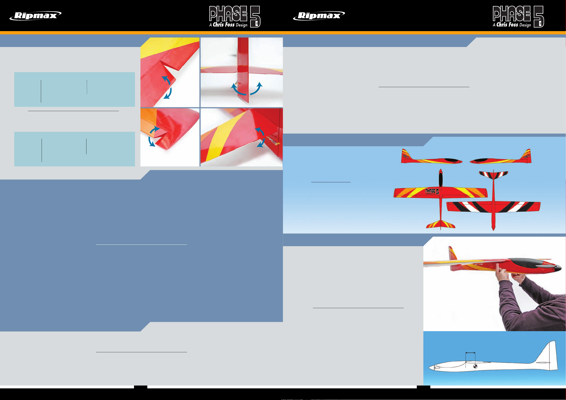
You are now ready to apply the supplied
decals. One at a time, carefully remove the
decals from their backing sheet, apply to
the model relative to the +diagram right and
gently smooth down.
While the Phase 5 is not a trainer, it does make an excellent first aileron model with reduced control throws. In this case, we recommend
that your completed model is checked over and test flown by a competent pilot first. Subsequent flights should also be supervised, and
assisted where necessary by an experienced pilot. Always fly the Phase 5 in a safe location at a recognised club. For further information
on flying in the UK, please contact: - British Model Flying Association (BMFA), Chacksfield House, 31 St Andrews Road, Leicester, LE2
8RE. Tel: +44 (0) 116 2440028 Fax: +44 (0) 116 2440645 or visit www.bmfa.org
• Completely charge your transmitter and flight batteries before flying.
• Carefully check your model over to ensure that all screws are tight.
• Double-check the Phase 5’ Centre of Gravity.
• Check the control surfaces for both the correct throw & direction and ensure that each moves freely, without binding.
Da der Phase 5 kein Trainer ist, bietet er sich als perfektes erstes Querruder Modell mit reduzierten Ausschlägen an. In diesem Fall
empfehlen wir, dass das Modell von einem erfahrenen Piloten überprüft, und eingeflogen sein sollte. Der Erstflug sollte in jedem Fall auch
von diesem mit überwacht werden, damit er im Notfall eingreifen kann. Fliegen Sie
den Phase 5 nur in ausgewiesenen Fluggebieten. Für weitere diesbezügliche Informationen wenden Sie sich bitte an Ihren Fachhändler,
oder den DMFV (Deutscher Modellflieger Verband).
• Laden Sie Ihren Sender und Flugakku komplett auf, bevor Sie fliegen.
• Vergewissern Sie sich, dass alle Schrauben an Ihrem Modell festgezogen sind.
• Überprüfen Sie den Schwerpunkt des Phase 5
• Überprüfen Sie alle Ruder auf korrekte Richtung, und richtige Ausschläge. Stellen Sie sicher, dass sich die
Ruder ohne Widerstand frei bewegen können, und sich nicht verwinden.
Spare Parts / Ersatzteile
Spare parts are available for the Phase 5 from all Ripmax stocked model shops. In case of any difficulty, any product queries, or to locate
your local Ripmax stockist, please visit www.ripmax.com
Ersatzteile sind für den Phase 5 in allen Ripmax Modellfachgeschäften verfügbar. Sollten Sie irgendwelche Schwierigkeiten mit Ihrem
Produkt haben, oder den örtlichen Ripmax Fachhändler nicht finden, dann schreiben Sie bitte an die unten angegeben Adresse, oder
besuchen Sie unsere Webseite unter www.ripmax.de
Nun können Sie die mitgelieferten
Dekors anbringen.Ziehen Sie diese
einzeln von der Trägerfolie ab und
bringen Sie diese sorgfältig gemäß
Zeichnung Recht an den entsprechenden
Stellen an.
Balancing / Schwerpunkt
The Centre of Gravity (C/G or Balance Point) should be
72-78mm back from the leading edge of the wing at the root.
This should be measured with the battery pack installed. Support
the completed model under the wing either side of the fuselage
at this point and add weight or adjust the position of the flight
battery in its bay as necessary to achieve a slightly nose down
attitude. A model that is not correctly balanced will not perform
as it should and, at worst, be unstable or unflyable, leading to
damage to the model or injury to yourself or others. Do not miss
out this step in completing your Phase 5!
Der Schwerpunkt des Modells (C/G oder Balance Point) sollte
bei 72-78mm liegen. Gemessen wird dieses von der Nasenleiste
(Flügelvorderkante) aus nach hinten. Dies muss mit eingebautem
Akku Pack gemessen werden. Stützen Sie das vervollständigte
Modell an der Unterseite des Flügels nahe des
Rumpfes, und geben Gewicht dazu, oder verändern die Position
des Akkus wenn nötig, damit sich die Nase leicht nach unten
neigt. Ein nicht korrekt ausbalanciertes Modell erreicht nicht die
Flugleistung, die es soll. Im schlechtesten Falle wird es unstabil
oder nicht fliegbar. Dadurch kann es zu Schäden am Modell,
oder zu Verletzungen von Ihnen oder anderen kommen. Lassen
Sie diesen Schritt nicht bei der Fertigstellung Ihres Phase 5 aus!
72-78mm
161716
17
Page 11

Ripmax Ltd.
241 Green Street,
Enfield, EN3 7SJ
United Kingdom
Tel: +44 (0) 20 82827500
Email: [email protected]
Website: www.ripmax.com
Ripmax GmbH
Futaba RC - Service
Stuttgarter Straße 20/22
75179 Pforzheim
Tel: +49(0)7231 46 94 10
Email: [email protected]
Website: www.ripmax.de
This manual my be subject to errors, omissions
Irrtum und technische Änderungen vorbehalten.
and technical changes.
© Ripmax 2018
Copying or reproduction, even in parts require written
permission of Ripmax Ltd.
© Ripmax 2018
Kopie und Nachdruck, auch auszugsweise, nur mit
schriftlicher Genehmigung der Ripmax Ltd.
Made in China
Manufactured for and distributed to your local model shop by: Ripmax Ltd., 241 Green Street, Enfield, EN3 7SJ. United Kingdom.
 Loading...