


Instruction
Manual
Specification:
Wingspan: 1332mm (51.3”)
Length: 1055mm (41.5”)
Weight: 1660g (Approx.)
Radio: 4-5 Channel (Required)
IC Engine: Irvine .36 or .39 (Recommended)

Page 2
Congratulations on your purchase of the J!VE Fun Fly.
This fun model is ideal for use as a sports model or
top level competition machine using its large control
surfaces and detachable Side Force Generators.
Before you build the model, please read the
instructions the whole way through to understand the
construction sequence.
• Wings
• Ailerons (x2)
• Fuselage
• Tailplane
• Elevator
• Fin
• Rudder
• Side Force Generators (x2)
• Tail Skid
• Dowel Rods (x2)
• Engine Mount
• Undercarriage
• Wheels
• Hardware Pack
• Closed Loop Pack
• Packing Foam
• Fuel Tank
• Velcro Strips
• Decal Sheet
• 5 Minute Epoxy
• Thin & Medium Cyano
• Screwdriver (X Head)
• Adjustable Spanner
• Wire Cutters
• Drill & Drill Bits
• Knife & Sharp Blades
• 4~5 Channel Radio
• 4x Standard Servos
• 1x Mini Servo
• 2x 200mm Extension Lead
• 2x 100mm Extension Lead
• Switch Assembly
• 4.8v 1000mAh Square
Battery
• Fuel Tubing
• .36 ~ .39 2-Stroke Engine
• Wing Bands
Introduction
Contents
Required to Complete

Page 3
The hinges are all supplied loose fitted ready for
installation. Glue the hinges into the ailerons with
a couple of drops of thin cyano on each to secure.
Ensure the glue soaks into the hinge & surrounding
wood.
Slot the aileron onto the hinges, ensuring a gap free
hinge line and making sure both ailerons line up with
the wing tips. Minimise any hinge gap then add a
couple of drops of cyano to each hinge. Turn the wing
over and drop more cyano onto each hinge.
Connect an extension lead to your aileron servo. It is
a good idea to secure the extension using a lead-lock,
insulation tape or heat-shrink tube.
Cut the film away from the servo aperture in the
bottom of the wing.
Tie the end of the extension lead to one end of the
string in the wing.
Step 1
Step 2
Step 3
Step 4
Step 5

Page 4
Cut away the film from the hole in the centre of the
wing. You can now pull the string gently through the
hole and feed out the extension lead.
Position the aileron servo in the wing with the horn
pointing towards the wing tip and output arm towards
the trailing edge of the wing. Now pilot-drill holes for
the mounting screws with a small drill.
Fit the rubber grommets and ferrules, then screw the
servo in position using the screws supplied with your
servo.
Position the aileron horn 1mm back from the leading
edge on the underside of the aileron in the centre of
the ply reinforcement as per
the diagram. Pilot-drill the
holes for the mounting
screws.
Screw on the aileron horn, ensuring you hold the horn
back plate in position so that the mounting screws
thread into the moulded back plate.
Step 6
Step 7
Step 8
Step 9
Step 10
1mm

Page 5
Turn the wing over and trim off any excess thread
using side cutters.
Now hold the aileron pushrod wire firmly and attach
a plastic clevis.
Clip the clevis onto the horn in the hole 2nd out from
the surface of the wing.
With the aileron held in its neutral position and the
servo centred, mark the wire where it crosses the
servo arm. If the wing is fitted to the fuselage, the
ailerons are at neutral when the bottom surface of
the trailing edge is 7mm above the surface of the
fuselage.
Bend the wire up at 90 degrees where marked.
Step 11
Step 12
Step 13
Step 14
Step 15

Page 6
Slide the aileron servo horn over the wire, re-fit to the
servo, then slide the swing-in keeper onto the wire and
clip into place.
Trim the excess wire 2mm above the keeper using side
cutters.
Repeat this process for the other aileron servo.
If you wish to use the Side Force Generators, trim the
covering away from the bolt holes on the wing tips.
Also trim the covering away from the mounting holes
on both sides of the Side Force Generators.
Bolt the Side Force Generators to the wing tips using
the nylon bolts supplied.
Step 16
Step 17
Step 18
Step 19
Step 20

Page 7
Install the “Aileron 1” and “Aileron 2” identification
tags to the extension leads.
Secure the hinges in the tailplane using a couple of
drops of cyano on each.
Slot the elevator onto the hinges keeping the hinge
gap to a minimum and run thin cyano in the hinges on
both sides, ensuring the glue soaks into the hinge and
surrounding wood.
Now secure the hinges into the fin using a couple of
drops of cyano on each.
Slot the rudder onto the hinges and keeping the hinge
gap to a minimum, run cyano into both sides of each
hinge.
Step 21
Step 22
Step 23
Step 24
Step 25

Page 8
Place the tailplane in position on the fuselage and turn
it upside down. Carefully check that the tailplane is
square and centred in relation to the fuselage. Now
mark the position of the fuselage on the tailplane.
Using a sharp knife blade, carefully cut the film from
the tailplane inside the marked lines.
IMPORTANT: Do not cut the wood, as this will
seriously weaken the tailplane.
Thoroughly mix up some 5 minute epoxy.
Apply the epoxy evenly to the fuselage.
Position the tailplane on the fuselage ensuring it is
square and hold firmly in position until the glue has
cured.
Step 26
Step 27
Step 28
Step 29
Step 30

Page 9
Carefully cut the film away from the fin slot.
Place the fin in its slot and mark the position of the
fuselage on the film on the fin.
Mark the fuselage where the fin is positioned. Remove
the fin then cut and remove the film from the fuselage
so that the fin has a completely film free surface to
bond to.
Cut the film away from the bottom of the fin below the
marked lines.
IMPORTANT: Do not the cut the wood, as this will
seriously weaken the structure.
Thoroughly mix some 5 minute epoxy and apply it to
the base of the fin and where it joins the fuselage.
Step 31
Step 32
Step 33
Step 34
Step 35
Page 10
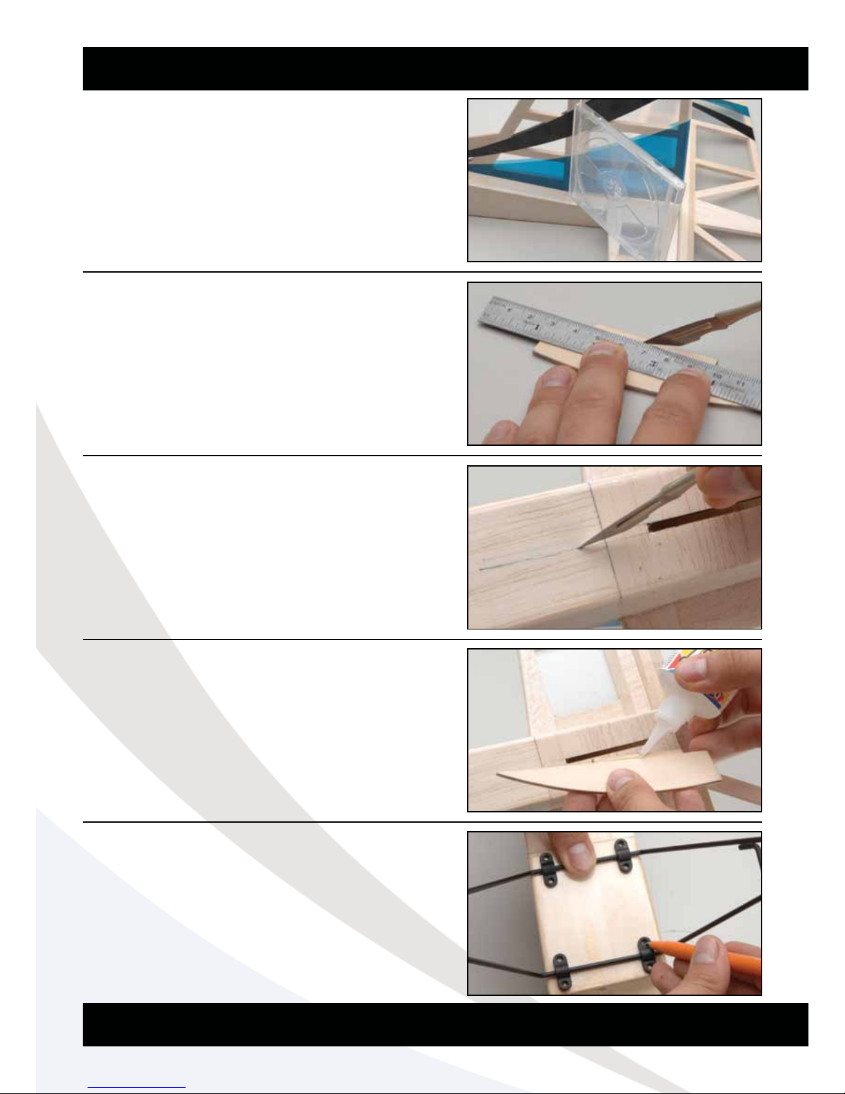
Glue the fin in position in its slot in the fuselage. A
great way to ensure the fin is perpendicular to the
tailplane is to use an empty CD case or set square.
Just as you did with the fin, trim the excess film from
the tab on the tail skid.
Trim away the film from the slot in the bottom of the
fuselage. Insert the skid and mark its position then
remove it and cut the excess film away from the
fuselage.
Now glue the skid in place using thick cyano,
ensuring that it is square to the fuselage.
Place the landing gear in position at the front of the
fuselage ensuring that it is centred on its plywood
mounting plate. Clip the mounting brackets in place as
shown and mark the position of the mounting holes.
Step 36
Step 37
Step 38
Step 39
Step 40

Page 11
Pilot-drill the holes for the retaining screws.
Screw the landing gear in position. Note that the
undercarriage should be angled forwards.
Install the wheels by fitting a collet on the axle, then
install the wheel, followed by another collet. Take care
to ensure the wheel moves freely but doesn’t slide
sideways on the axle. Tighten the grubscrews in both
collets using thread locking compound if required.
Trim away the film covering from the wing dowel
holes.
Place the wing dowels in position ensuring that they
are centred, then glue in place using thin cyano. Note
that the longer dowel is for the front and the shorter
dowel is for the rear.
Step 41
Step 42
Step 43
Step 44
Step 45
Page 12
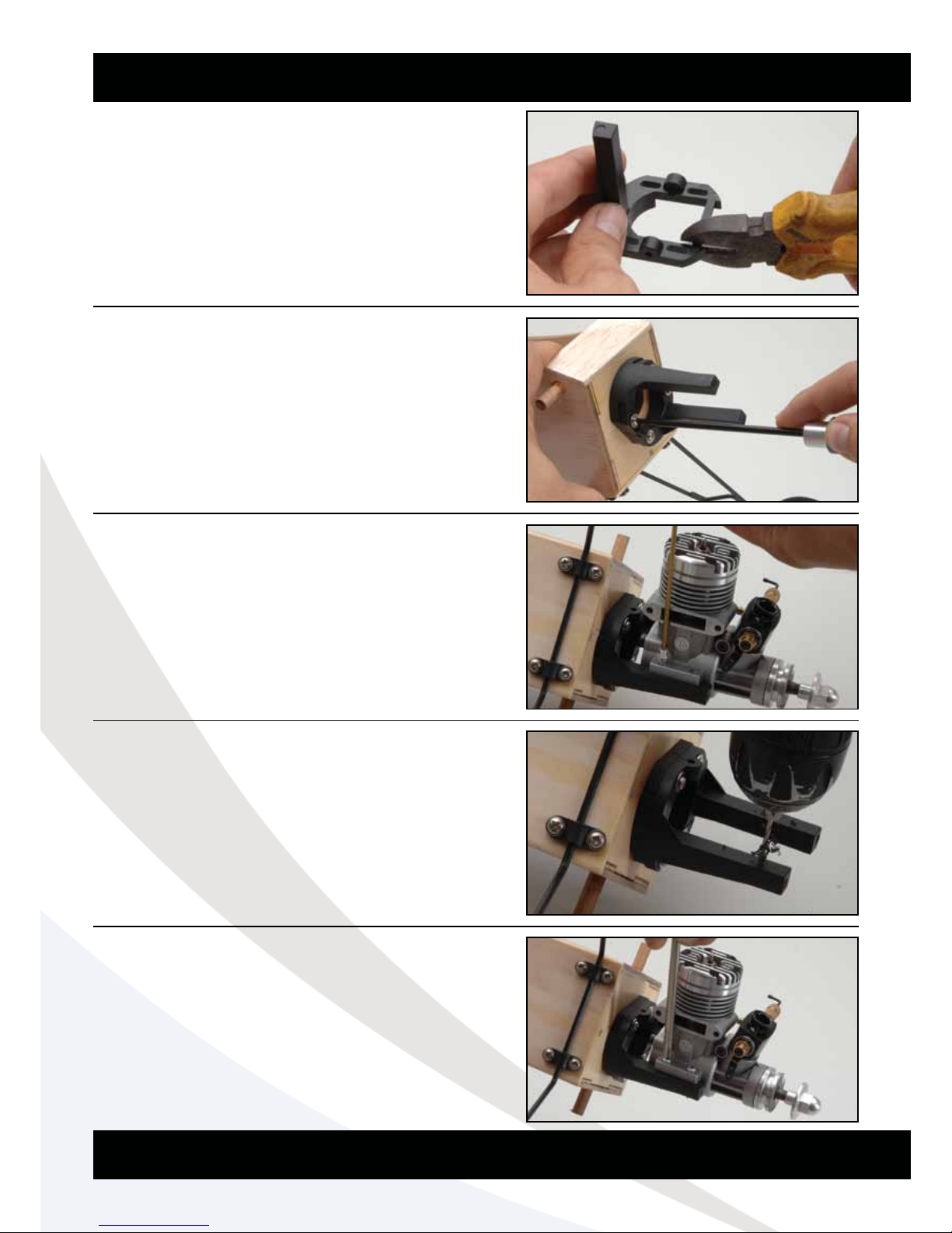
Cut the unused moulding away from the engine mount
as shown and trim flush.
Assemble the mount and position in place on the
firewall. Screw the mount in position but do not tighten
the screws fully yet.
Position the engine on the mount, ensuring there is
room for the fuel lines behind it and mark the engine
mounting holes.
Drill the holes for the self-tapping mounting screws. Do
not drill the holes too large or the screws will not be
secure.
Tighten the firewall mounting screws. Now screw the
engine firmly in place.
Step 46
Step 47
Step 48
Step 49
Step 50

Page 13
Bolt the silencer in position.
Assemble the bung for the fuel tank as shown. Bend
the breather pipe up and place that high in the rubber
bung, and the small pipe lower for the fuel feed. Use
the supplied thin walled tubing for the clunk ensuring
that the clunk doesn’t hit the back of the tank. Use the
screw and metal plates to tighten the bung in the neck
of the fuel tank.
Overlap the Velcro strips 30mm and glue them
together making a strap. Now feed the strap under
the fuel tank mounting plate as shown.
Wrap the fuel tank in a piece of foam, feed the two
fuel tubes through the firewall and retain the tank in
place with the velcro strap.
Screw the black clevis onto the bowden style throttle
cable. Slide the cable into the throttle tube from the
front and connect the clevis to the carburettor throttle
arm.
Step 51
Step 52
Step 53
Step 54
Step 55
Page 14
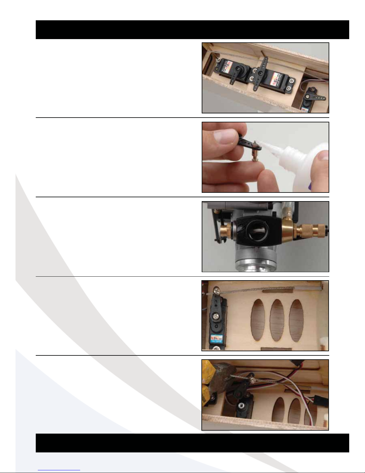
Pilot-drill the servo mounting holes and screw them in
place as shown right, noting the orientation. Use the
rubber grommets & ferrules supplied with your radio.
Install the pushrod connector to the throttle servo horn
and use a drop of cyano to secure the retaining nut in
place.
Position the carburettor half open.
With the throttle in its mid-position, screw the cable in
position with the horn at 90 degrees to the cable.
Remove any excess throttle cable using side cutters.
Step 56
Step 57
Step 58
Step 59
Step 60

Page 15
Cut the last hole off of the elevator horn and trim
along the red lines shown in
the diagram right.
Screw the clevis onto the elevator pushrod, and clip to
the horn.
Slide the elevator pushrod down the pushrod tube in
the fuselage and mark the position of the horn on the
elevator. Now screw the horn to the elevator
using the same method as
the ailerons.
With the elevator level and the elevator stick at its
neutral position, mark the elevator pushrod where it
crosses the elevator servo arm.
Bend the pushrod 90 degrees in the same way as the
ailerons and clip off any excess wire.
(Shown outside of the fuselage for clarity)
Step 61
Step 62
Step 63
Step 64
Step 65

Page 16
Connect the pushrod to the elevator horn and install
the swing-in keeper.
Cut the film away from the rudder control horn
mounting hole.
Assemble one half of the rudder closed loop horn as
shown.
Install the horn in the rudder checking carefully that it
is in the centre and tight. Then use a drop of cyano to
lock into position.
Cut the closed loop wire exactly in half using side
cutters.
Step 66
Step 67
Step 68
Step 69
Step 70

Page 17
Loop one end of wire through one of the closed loop
adaptors and slide the crimp tube over the looped
wire. Crimp the tube on the wire gently using a pair of
wire cutters at multiple points. For additional security
use a drop of cyano too.
Repeat for the other cable and adaptor.
Cut the film away from the closed loop cable tubes in
the fuselage. Connect the clevises fitted to the closed
loop adaptors to the rudder horn and slide the cables
down the tubes.
Slide a crimp tube over the cables and feed them
through the adaptors. Now clip the two remaining
adaptors (not screwed tight so there is still adjustment)
to the servo arm. Pull both cables tight keeping
the rudder straight and squeeze the cables at the
adaptors. This bends the wire so you can re-install it in
the same place as you crimp them separately.
Remove the arm from the servo to reduce tension.
Ensuring the cables are in the same position as the
bends carefully crimp the tubes to secure the cables
in place. Now re-attach the servo arm and slide the
retaining fuel tubes onto the clevises.
Cut off the excess cable a few millimetres after the
crimps. For additional security add some cyano onto
the wire crimps.
Step 71
Step 72
Step 73
Step 74
Step 75

Page 18
Install the battery on a piece of foam behind the fuel
tank using the same method as the fuel tank with the
remaining Velcro straps.
Mark and cut a hole for the switch in the balsa on the
right hand side of the fuselage.
Install the switch, being careful not to overtighten and
crush the balsa.
Install the receiver on the other side the fuselage using
two layers of double sided tape. There is extra tubing
included in the kit allowing you to glue them to the
side of the fuselage and slide the aerial wires in. At
this point connect your servo/switch/battery leads
and use the included cable ties to bundle the wires
neatly together and clear of the throttle servo.
Install your choice of Fun-Fly propeller and the
construction is complete.
Step 76
Step 77
Step 78
Step 79
Step 80

Page 19
For initial flights we recommend you fly with the sport
settings first until you get a ‘feel’ for the airframe.
Sport
Ailerons Up 35mm (35% Exponential)
Down 35mm (35% Exponential)
Elevator Up 30mm (30% Exponential)
Down 25mm (20% Exponential)
Rudder Left 50mm (0% Exponential)
Right 50mm (0% Exponential)
Advanced
Ailerons Up 70mm (50% Exponential)
Down 70mm (50% Exponential)
Elevator Up 55mm (50% Exponential)
Down 35mm (40% Exponential)
Rudder Left 75mm (25% Exponential)
Right 75mm (25% Exponential)
Flaperons
Enabling a flaperon mix will help the model to loop
tighter at slower speeds. On Advanced settings the
ailerons should move 30mm down with up elevator
and 20mm up with down elevator. If you can, add this
mix on a switch so that you can disable it for spins.
The Centre of Gravity (C/G or Balance Point) should
be 110mm (4.3”) back from the leading edge of the
wing at the root. This should be measured with the
fuel tank empty. Support the completed model under
the wing either side of the fuselage, add weight to the
model if needed to achieve a level attitude.
Do not miss out this important step!
Spare parts are available for the J!VE from all Ripmax
stocked model shops. In case of any difficulty, any
product queries, or to locate your local Ripmax
stockist, please write to the address below or visit
www.ripmax.com
Control Throws
Balancing the J!VE
Spare Parts and Service
Ripmax Ltd., 241 Green Street, Enfield, EN3 7SJ United Kingdom
110mm

Page 20
•Completelychargeyourtransmitterandreceiverbatteriesbeforeying.
•Carefullycheckyourmodelovertoensurethatallscrewsaretightandeverythingiswell
bonded.
•Double-checktheCentreofGravity.
•Checkthecontrolsurfacesforboththecorrectthrowanddirection.Ensurethateach
surface moves freely, without any binding.
•Ensurethewingbandsaresecure.
Always fly the J!VE in a safe location at a recognised club. For further information on flying in
the UK, please contact:
British Model Flying Association (BMFA)
Chacksfield House, Tel: (+44) 116 2440028
31 St Andrews Road, Fax: (+44) 116 2440645
Leicester. LE2 8RE www.bmfa.org
Fun fly models are designed for slow speed manoeuvrability and should be treated as such.
The J!VE can be flown at walking pace and will even fly backwards in a head wind! Above
50% throttle should only be used for climbing. Flying the airframe around at high throttle can
overload the large 3D surfaces and cause damage due to the stresses involved.
The undercarriage had been designed for use in touch and go competitions and has supports
half way down the wire legs. You can use rubber bands between them and increase the
strength for competition use.
The J!VE’s most noticeable feature are the wing tip plates or Side Force Generators. On the
J!VE they perform a few functions. They allow the model to fly in ‘knife edge’ with minimal
coupling and help to track the model straight at slower speeds. Try flying with and without
them to see the difference in flight performance.
Fun Fly style manoeuvres are about energy conservation and precision, despite how crazy
they may look! Use the diagrams on the next page as a guide on how to perform some of the
manoeuvres the J!VE excels at.
Pre-Flight Checks
Flying Notes

Page 21
To compete in limbo you have to fly under a ribbon
as many times as possible in a designated time. You
can loop around the ribbon or fly a tight circuit. The
score stops when you run out of time or cut the ribbon.
Typically an old VHS tape unreeled makes a great
ribbon to fly under. The limbo dimensions are 6ft high
& 25ft wide
Using the same techniques as the limbo you must
perform as many touch and gos in a designated area
(typically a 20ft box) within the time limit as you are
able.
One of the simpler events, climb and glide involves a
short time at full throttle (typically 20 seconds) to gain
height. You then cut the engine and glide for as long
as possible. Land in the a designated area (typically a
20ft box) for a 10% time bonus.
The triple thrash involves taking off, performing 3
Touch and Go’s, 3 rolls and then 3 loops. The timer
starts when the wheels leave the floor and stops when
they touch again. You must take off again to prove
you landed rather than ‘arrived’.
All events are scored out of 100. So the winner of
each event is awarded 100 points and the others are
calculated as a percentage of the highest score.
Limbo
Touch and Gos
Climb and Glide
Triple Thrash
Scoring
3x Rolls
3x Loops
3x Touch
& Go

Page 22
Climb and Glide
Limbo
Club Competition Chart
Photocopy to Use
Name Score
Name Score
Longest flight from 20 seconds of power.
Perform as many passes under the limbo ribbon as possible in 2 minutes.

Page 23
Triple Thrash
Touch and Gos
Photocopy to Use
Club Competition Chart
Name Score
Name Score
Perform three “Touch and Gos”, three rolls and three loops in the shortest time possible.
Perform as many touch and gos in the designated area in 2 Minutes.

Always Fly Responsibly and Safely.
Distributed to your local model shop by:
Ripmax Ltd., 241 Green Street, Enfield, EN3 7SJ. United Kingdom
Made in China
 Loading...