

Page 1

INSTRUCTION
MANUAL
Page 2
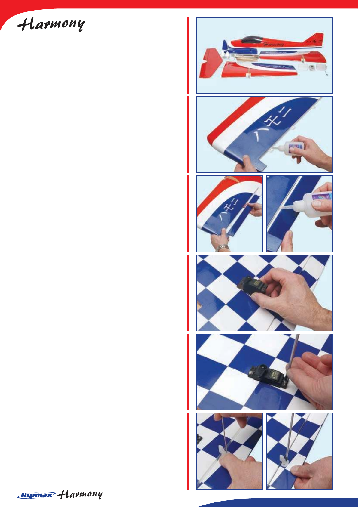
Congratulations on your purchase of the Ripmax
Harmony! Despite it being a twin, nal assembly is quick
and straightforward. We recommend that you read these
instructions fully before you commence assembly.
The Wings
STEP 1.
Locate the aileron hinges and insert 4 mid-way into each
wing half’s trailing edge (eight hinges in total). Each of
the slots has been pre-cut, but may need gentle opening
with a sharp knife. Using thin cyano, pour a couple of
drops onto each hinge - above and below - ensuring the
glue soaks into the hinge and the surrounding wood.
STEP 2.
Carefully slide each aileron into position, ensuring a gap
free hinge line. Make sure that each aileron is centred
between the root and tip and that they are free to move
through their entire travel. Carefully add a couple of
drops of thin cyano to the top and bottom of each hinge
ensuring that the glue does not run through the hinge
line onto the bottom of the wing. Turn the wing over and
drop more cyano onto each hinge from the other side.
STEP 3.
Cut away the covering lm from the aileron servo
apertures. Check that your choice of aileron servo ts
the pre-cut aperture. Adjust the size of the mounting
holes with a sharp knife if required. Carefully pass each
aileron lead through to the centre of the wing. You will
need to extend the length of your aileron servo leads
using a pair of extension leads. Note the orientation of
each servo - the output horn should face the front of
each wing panel.
STEP 4.
Fit the rubber servo mounting grommets and brass
ferrules supplied with your radio equipment in accordance
with the radio manufacturer’s instructions. Install the two
aileron servos in their mounts. Screw each servo into
position.
STEP 5.
The aileron horns are mounted on the underside of each
aileron, in line with the servo output arm and the hinge
line. Use a small drill to mark the horn’s position on the
aileron then drill clearance holes. Mount the two aileron
control horns using the screws provided. Do not overtighten the screws into the mounting plates.
Page 3
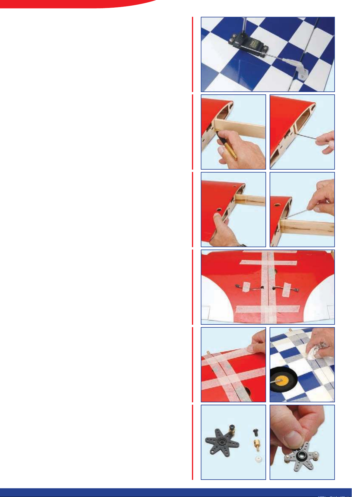
STEP 6.
Locate the aileron control rods with pre-formed z-bend
ends. Connect the control rods to the aileron servos and
tighten the servo horns. Check that both ailerons move
freely across their entire throw with no binding. Adjust
their neutral positions if necessary.
STEP 7.
Find the pre-cut wing joiner and ensuring it is correctly
orientated, dry assemble the two wing panels to ensure
they t together with no gaps between the root ribs.
Now mark the centre position of the joiner as shown. It
is a good idea to run a strip of masking tape around the
wing at the root to protect it. Mix up sufcient epoxy (30
minute or 1 hour type recommended) and work plenty
into the wing joiner pocket.
STEP 8.
Liberally coat one half of the wing joiner front and back,
top and bottom. Carefully push it fully into its pocket,
removing any excess epoxy that runs out. Now coat the
second half of the joiner and the face of the root rib.
Work plenty of epoxy into the second wing joiner pocket
as before.
STEP 9.
Working over sheet of polythene to avoid epoxy
damaging your work surface, draw the two wing panels
together. Make sure that you don’t allow excess epoxy
to run onto the servo leads or retract pushrods as the
two panels meet together. Ensure aileron servo leads
exit through access holes in top of wing.
STEP 10.
Ensuring that the two wing panels are accurately aligned,
use tape to secure them as the epoxy cures. Check that
there are no gaps between the root ribs. There should
be a small amount of dihedral on the underside of the
wing only (the top surface of the wing should be at) but
this is assured when the root ribs meet together. Wipe
off any excess epoxy from the wing join, then leave the
wing to one side for the epoxy to cure thoroughly.
STEP 11.
To complete the retract linkage, locate the two metal
pushrod connectors and t them to a suitable servo
output horn. You will need to measure the distance each
operating pushrod needs to move to fully extend and
retract your undercarriage and choose an output horn
that will give this operating throw.
Page 4
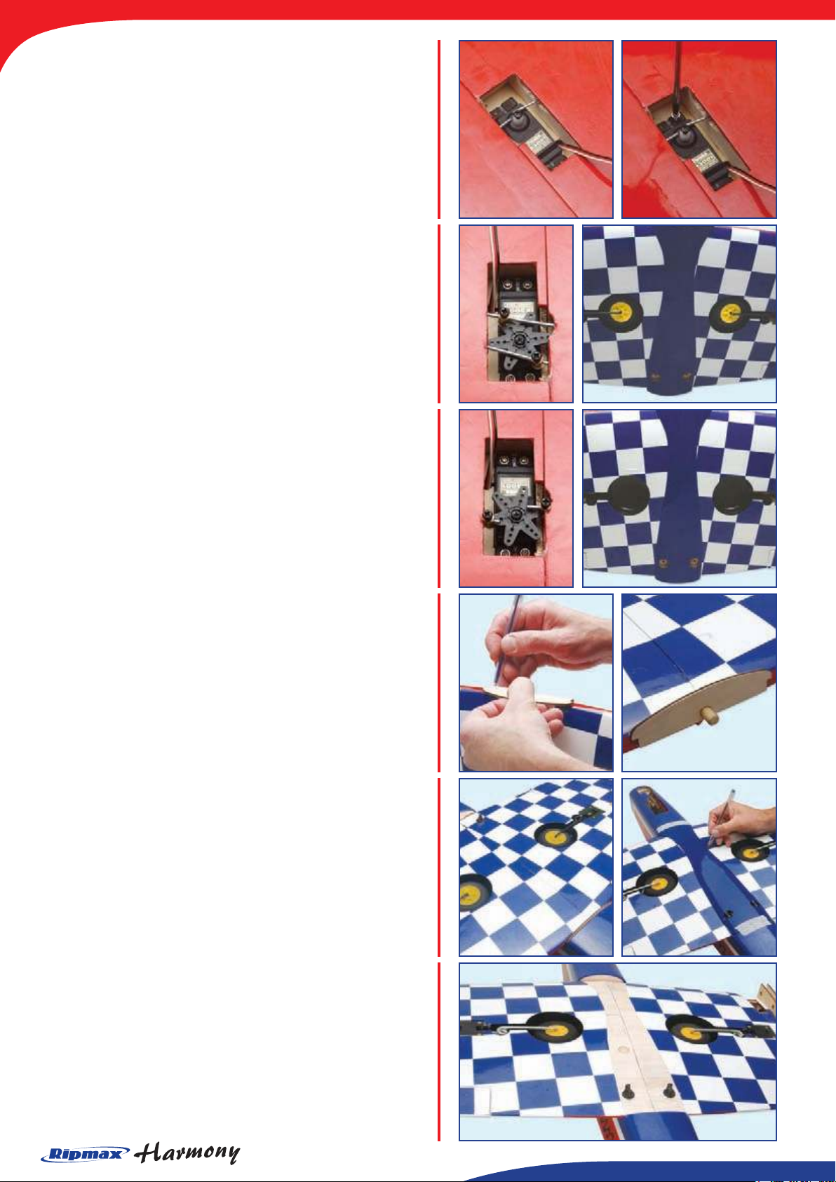
STEP 12.
Check that your choice of retract servo ts the pre-cut
aperture. Adjust the size of the mounting hole with a
sharp knife if required. Note that the servo may extend
through the underside of the wing so trim away the
covering to allow this if necessary. Fit the rubber servo
mounting grommets and brass ferrules then pilot drill
and screw your servo in position.
STEP 13.
Fit the prepared servo output horn and slide the retract
operating pushrods through the connectors. It may be
easier to remove the retract mounting screws for this
so that each unit can be slid part way out of its mount
during connection and adjustment of the linkage.
Once happy with the operation of the retracts, fully
tighten the connectors and re-t all eight retract mounting
screws.
STEP 14.
Locate the wing mounting dowel and slide it into its
pre-cut hole in the leading edge, trimming the covering
if necessary. Slide the plywood underwing fairing former
over the dowel and with its curved surface to the bottom
of the wing, mark its shape onto the lm. Remove the
marked section of lm with a sharp knife and epoxy the
former and dowel in position as shown.
STEP 15.
Once the epoxy has fully cured, temporarily bolt the
wing to the fuselage using the two nylon retaining bolts.
Holding the underwing fairing in place - ensuring it is
centred front and back, left and right - mark its position
with a felt pen. Do not press too hard on the fairing
otherwise it may distort and spread wider than the
fuselage.
STEP 16.
Remove the fairing and carefully trim inside the lines you
just marked using a sharp knife. VERY IMPORTANT:
Make sure that you do not cut into the wood otherwise
the strength of the wing will be severely weakened. Prior
to gluing the fairing in place, you may like to protect
the fuselage with clear tape or lm so that you do not
accidentally glue the wing to the fuselage in the next
step!
Page 5
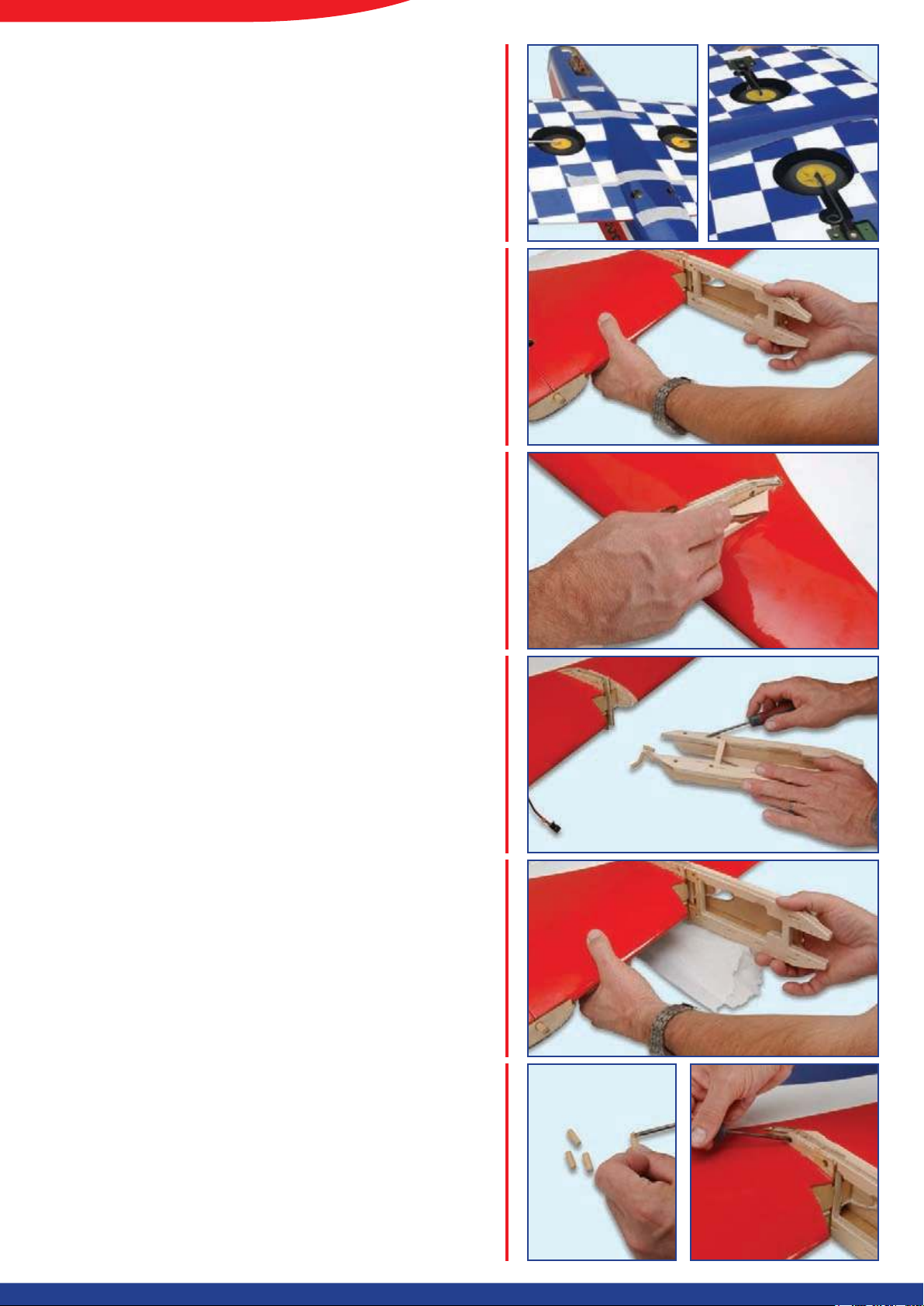
STEP 17.
Using 5 minute epoxy or thick cyano, run a bead of glue
around the perimeter of the underwing fairing and over
the underwing fairing former. Avoid using too much glue
as any excess will simply run out onto the wing covering
or bond the fairing to the fuselage rather than the wing.
Use strips of masking tape to hold the fairing in place
until the glue dries.
The Engine Nacelles
STEP 18.
Locate the two plywood engine mounting plates. Note
that they are handed for the left and right wing and only
t one way round. Dry t the mounting plates to ensure
that they locate correctly in the wing. Each mounting
plate slides into the pre-formed plywood mounting points
and has four dowel security pegs on each.
STEP 19.
With each mounting plate temporarily tted in place,
mark the covering where the plywood strengtheners
touch. The covering must be carefully cut away from
these areas using a sharp knife making sure that the
surface of the wing is not cut.
STEP 20.
Mix sufcient epoxy - 30 minute type is recommended
- and apply it liberally to the engine mounting plate and
the plywood mounting point in the wing. Only work on
one mount at a time and ensure that all surfaces are
well coated as any excess can be wiped away before it
cures.
STEP 20.
Slide the mounting plate in position ensuring that it seats
fully home in its mount. Work with tissue underneath, so
that any excess epoxy that oozes out of the joint does
not damage your work surface.
STEP 21.
Coat each of the four security dowels with epoxy and
push them through the plywood mount ensuring that they
pass completely through both sides. Use clamps or tape
to hold the assembly together as the glue cures. Wipe
any excess glue from the mounting plates but make sure
there are no gaps between the mount and wing. Repeat
the procedure for the second engine mounting plate.
Page 6
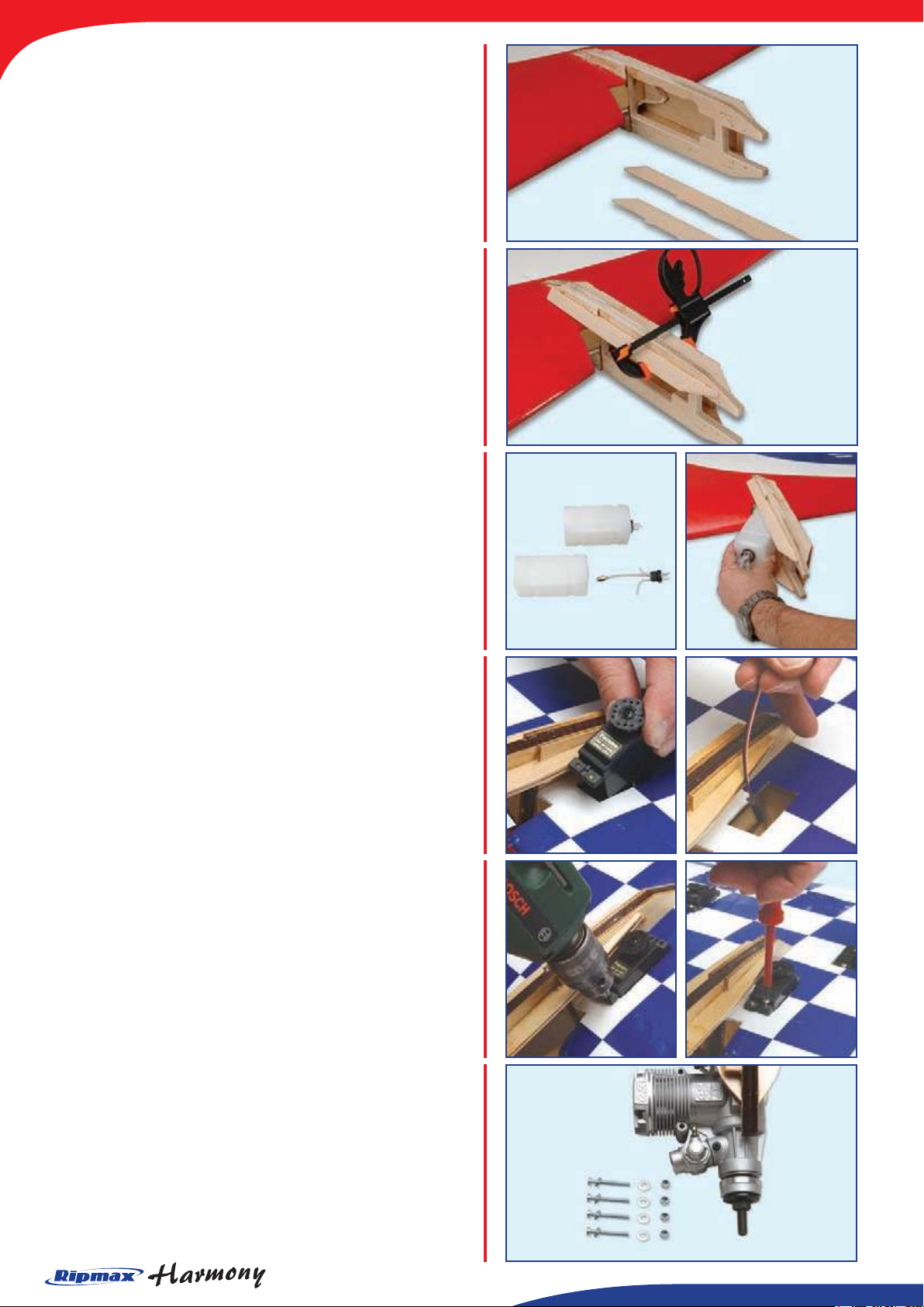
STEP 22.
Once the epoxy has cured, locate the plywood engine
mount reinforcing plates. These stiffen the mount
assembly considerably.
STEP 23.
Mix up some 5 minute epoxy and glue the upper and
lower reinforcing plates in position. Use clamps to
secure as the epoxy cures.
Now repeat the procedure for the other side.
STEP 24.
Prepare the two fuel tanks as shown. Cut the clunk tubes
to the correct length so that the two clunks are free to
move inside the tanks without touching restriction. Insert
each tank into the engine mount as shown. Use a dash
of silicone sealant to retain each of the tanks in position.
Check that fuel output and vent pipes clear the mount,
the tubing can run either side.
STEP 25.
Check that your choice of throttle servo ts the pre-cut
apertures. Adjust the size of the mounting holes with a
sharp knife if required. Fit the rubber servo mounting
grommets and brass ferrules supplied with your servos.
Extend the length of the servo lead or t an extension
lead to each servo and thread them though the wing and
out of the forward exit hole in the wing centre section.
STEP 26.
Drill four pilot holes for each, then mount the servos
using the screws supplied with your radio equipment.
STEP 27.
The Harmony is designed for a pair of .40 or .46 engines
- the O.S. 46 AX being particularly recommended. Each
engine is mounted with its silencer facing down using
the mounting screws, washers and nyloc nuts supplied.
Attach each engine to its mount leaving the silencers off
at this stage.
Page 7
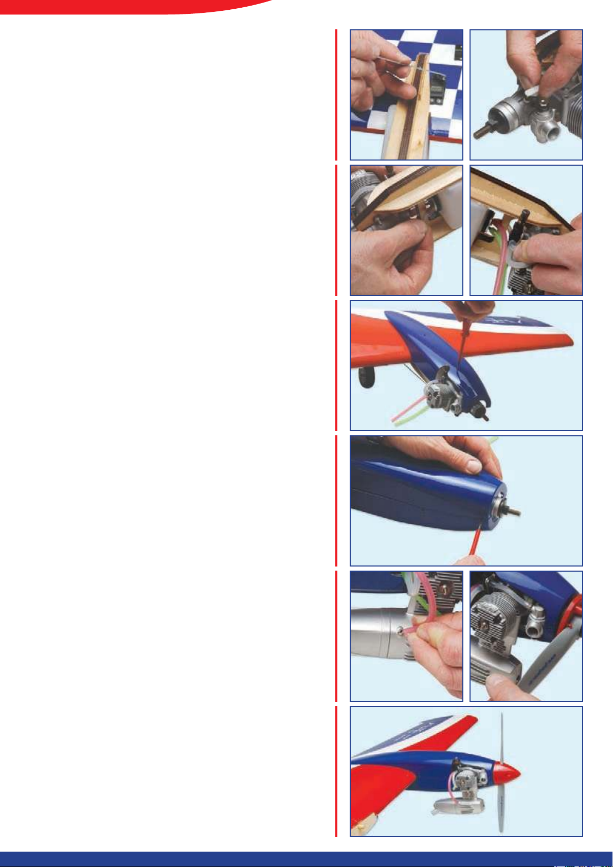
STEP 28.
Screw a clevis onto each throttle pushrod, thread the
z-bend through the servo’s output horn, then connect
to each engine’s throttle arm. Adjust the rod lengths
carefully to ensure that if you are connecting the servos
via a ‘Y’ lead that the idle and high speed positions
match.
STEP 29.
Complete the engine installation by plumbing the
engine’s fuel, ll and pressure lines. It is a good idea to
use different colour fuel lines so that the installation is
nice and clear and plumbing errors are avoided.
STEP 30.
Test t the moulded nacelles. Note that they are handed
for the left and right wing and only t one way round.
Trim the top half to clear the needle valve assembly and
retain it in position using two self tapping screws into the
engine mount after pilot drilling the holes.
STEP 31.
Fit the lower nacelle in the same way after carefully
trimming it to clear the silencer. Use tape to hold it in
position, then pilot drill and t two self tapping screws to
retain the lower nacelle moulding to the engine mount.
Use a further six self tapping screws - three per side of
each nacelle - to seal the joins between the two nacelle
halves as shown.
STEP 32.
Now connect up the prepared fuel lines - if you used
different colour tubing, this is an easy task! Ensure that
the silencer is tight and the pressure line connected.
Blank off the vent line with a plug. Now t your propeller
and spinner and tighten with the correct spanner or
wrench.
STEP 33.
Once the second nacelle has been completed in the
same way you have completed the wing assembly. Take
a few moments now to carefully mark the aileron, throttle
and retract servo leads so that they are easily identied
when rigging the model.
Page 8
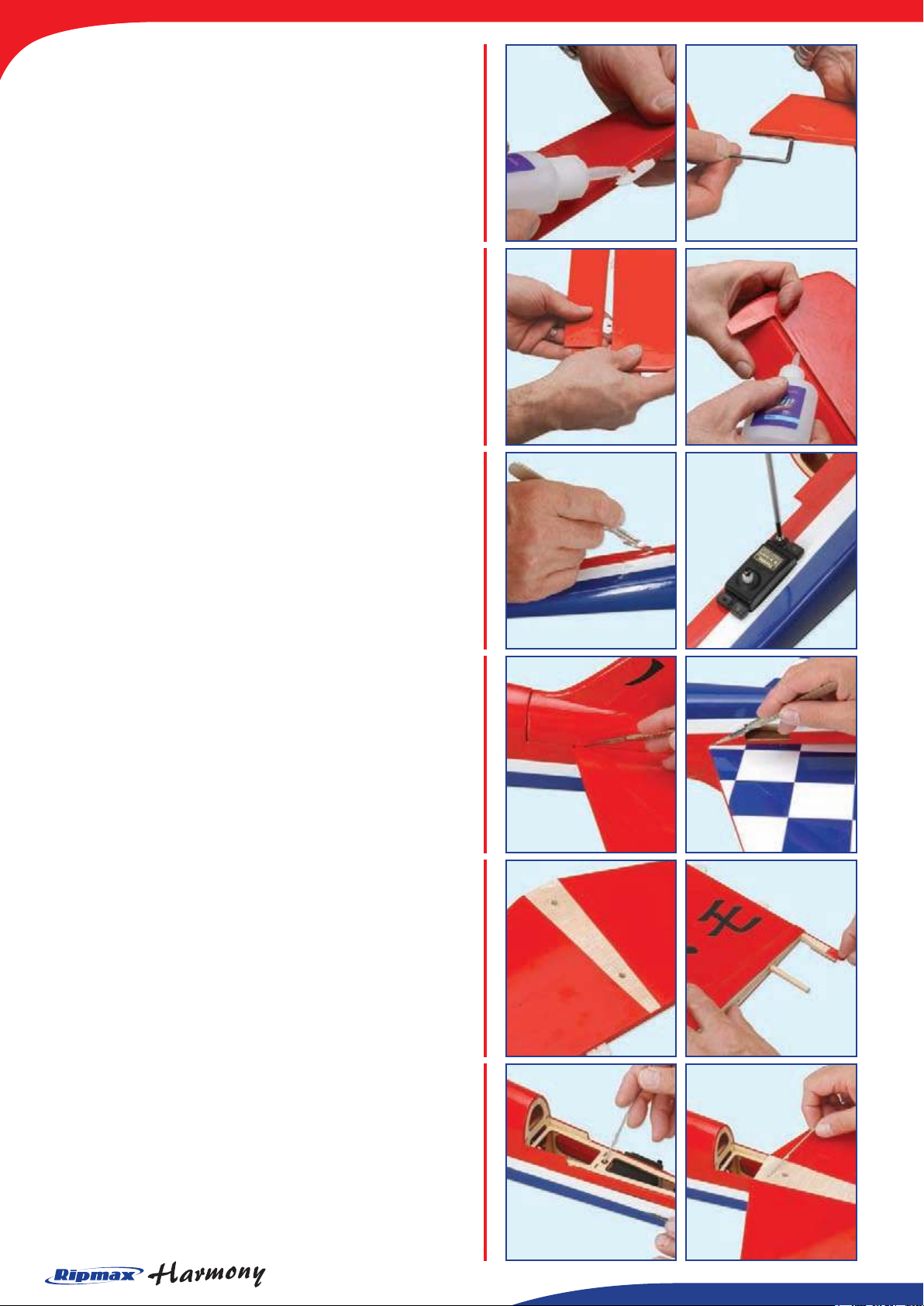
The Tailplane and Fin
STEP 34.
Locate the elevator hinges and insert 3 mid-way into each
elevator. Use thin cyano to secure each hinge, ensuring
the glue soaks into the hinge and the surrounding wood.
Now join the two elevator halves using the pre-bent wire
elevator joiner coated with epoxy and inserted into the
drilled holes in each elevator half. While the glue cures,
ensure both elevator halves remained aligned.
STEP 35.
Slide the elevator assembly into position, ensuring a
gap-free hinge line. Make sure that elevator is centred
between the tailplane tips and that it is free to move
through its entire travel. Now carefully add a couple of
drops of thin cyano to the top and bottom of each hinge
ensuring that the glue does not run through the hinge
line onto the bottom of the tail. Turn the tail over and
drop more cyano onto each hinge from the other side.
STEP 36.
Trim away the covering from the pre-cut elevator servo
aperture. Extend the length of the servo lead, or use
and extension lead, then thread the lead through the
fuselage up to the radio bay. Noting the orientation, t
the rubber servo mounting grommets and brass ferrules
supplied with your radio and install the servo.
STEP 37.
Now position the tailplane over its pre-formed mount
in the fuselage. Locate the n and carefully pass the
wooden dowels in the n’s base through the tailplane
and into the bottom of the fuselage. Using the fuselage
and fairing as a guide, score the lm on the tailplane top
and bottom using a sharp knife.
STEP 38.
Ensuring that you don’t cut into the tailplane, cut the
lm at the scored lines and remove the covering on the
top and bottom of the tailplane as shown. Remove the
covering from the rudder post in the same way.
STEP 39.
Now mix up sufcient epoxy (30 minute recommended)
and apply to the tailplane mount in the fuselage. Fit the
tailplane, then add more epoxy to the top of the tailplane
and the rest of the fuselage opening where the n fairing
will t and move straight onto the next step
Page 9
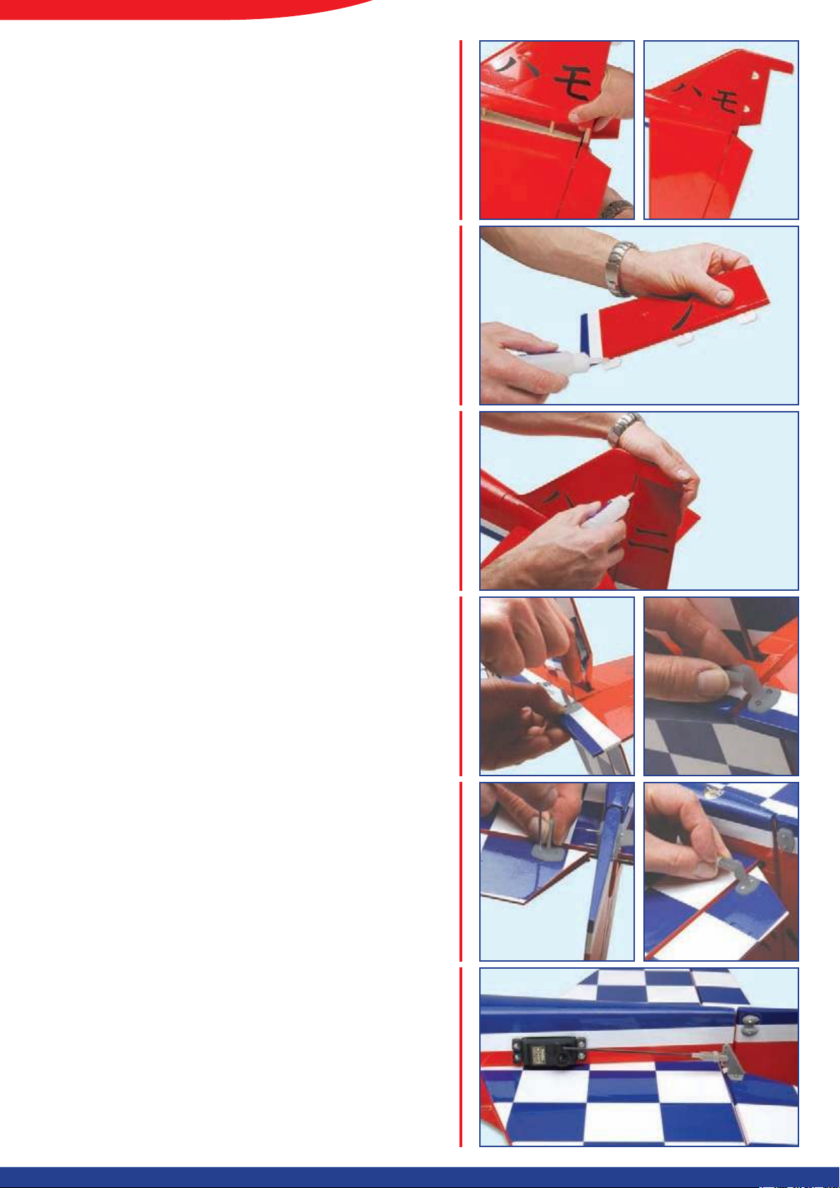
STEP 40.
Coat the underside of the n fairing and the two dowels
with more epoxy. Thread the dowels through the holes
in the tailplane and push the n fully into position. Use
a tissue to remove any excess epoxy and check for the
correct alignment of the tail and the n while the epoxy
cures.
STEP 41.
Locate the rudder hinges and insert 3 mid-way into
rudder. Using thin cyano, pour a couple of drops onto
each hinge - above and below - ensuring the glue soaks
into the hinge and the surrounding wood.
STEP 42.
Slide the rudder into position, ensuring a gap-free hinge
line. Make sure that rudder is centred between the n tip
and the bottom of the fuselage. Check it is free to move
through its entire travel. Now carefully add a couple of
drops of thin cyano to each hinge ensuring that the glue
does not run through the hinge line onto the other side
of the n. Turn the model over and drop more cyano
onto each hinge from the other side.
STEP 43.
Screw a clevis onto the rudder pushrod and slide it into
the fuselage from the rear of the model. Now attach a
control horn onto the left-hand side of the rudder in line
with the pushrod and aligned with the hinge line. Snap
the clevis closed as you will complete the rest of the
rudder linkage once the nose retract is tted.
STEP 44.
Screw a clevis onto the elevator pushrod. Now attach a
control horn onto the underside of the right-hand side of
the elevator in line with the already tted elevator servo
and aligned with the hinge line. Pilot drill the mounting
holes, screw the horn in place, cutting off any excess
screw length that passes through the retaining plate.
STEP 45.
With the elevator and elevator servo centred, adjust the
clevis until the rod is the correct length. Snap the clevis
closed, then test to ensure that the elevator moves
through its entire travel without binding.
Page 10
Nose Retract
STEP 46.
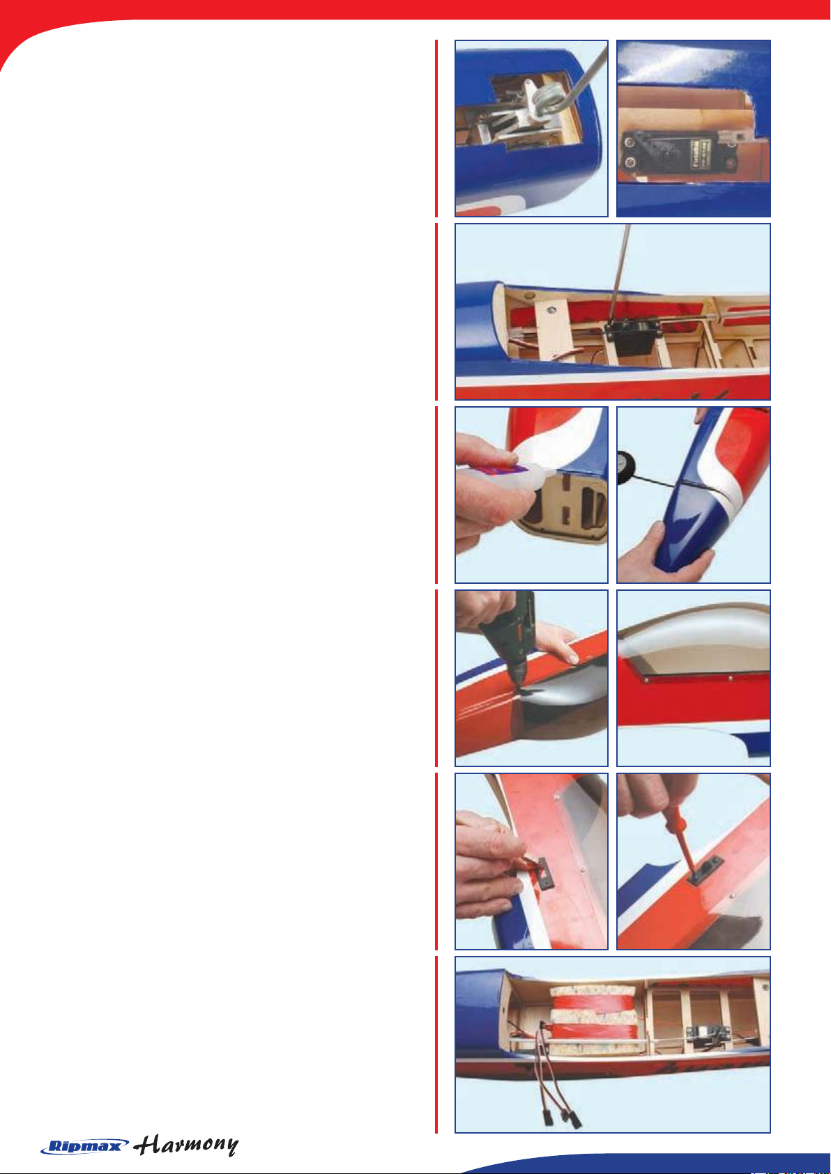
The nose retract comes pre-tted. Mount your servo in
the pre-cut bay immediately behind the retract unit using
the grommets, ferrules and screws supplied with your
radio. Fit a clevis to the retract pushrod and connect.
Adjust the length of the rod so the noseleg retracts and
extends without binding.
STEP 47.
To complete the rudder and steerable linkage, install
your rudder servo in the pre-cut tray in the fuselage as
shown using the grommets, ferrules and screws supplied
with your radio. Now t two metal pushrod connectors to
the servo output arm and slide them over the noseleg
steering and rudder pushrods before tting to the servo.
Centre the servo, noseleg and rudder before tightening
the retaining screws.
STEP 48.
The moulded nose-cone can now be tted. Check
the t of the nose-cone and trim with a sharp knife if
required. Run a bead of thick cyano around the front of
the fuselage and glue the nose-cone in position.
Final Assembly
STEP 49.
The canopy can be tted using canopy glue or with the
six self-tapping screws supplied. If using the latter, hold
the canopy in place using tape after centring it so that
the overlap onto the fuselage is even on both sides.
Carefully pilot drill and t the six retaining screws as
shown.
STEP 50.
There is a pre-cut hole for the switch in the right hand
fuselage side just below the canopy. Locate its position
and trima away the covering for the switch and mounting
screws. Screw the switch in postion.
STEP 51.
Complete the radio installation by packing both the
receiver and nicad in protective foam in the radio bay
as shown. The nal position of the battery should be
determined by the model’s balance point - moving it
forward or rearward in the radio bay to ensure the model
balances correctly.
Page 11
STEP 52.
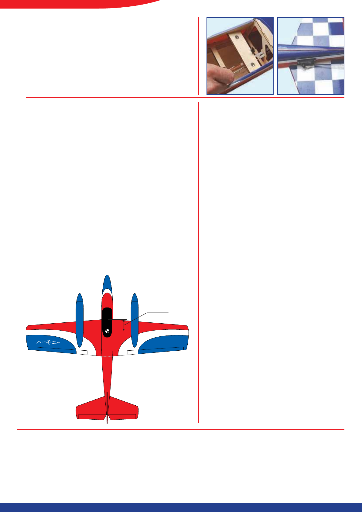
90-100mm
The aerial should be routed through the nal remaining
tube in the rear of the fuselage and retained with tape
where it exits at the rear.
Congratulations - you have
completed the assembly!
Control Throws:
For initial ights, we recommend the following:-
Elevator: 17-20mm up and 17-20mm down
Ailerons: 17-20mm up and 17-20mm down
Rudder: 50mm left and 50mm right
Once comfortable with the Harmony the control throws
can be increased to suit your ying style, however, these
are a good starting point for the majority of pilots.
Balancing the Model
The Centre of Gravity position should be 90-100mm back
from the leading edge measured at the root of the wing.
Support the completed model at this point and move
the model’s battery forward or rearward as necessary
to achieve a slightly nose down attitude. A model that is
not correctly balanced will not perform as it should and,
at worst, be unstable or unyable, leading to damage to
the model or injury to yourself or others. Do not miss out
this step in completing your Harmony!
Pre-Flight Checks
• Completely charge your transmitter and
receiver batteries before ying.
• Carefully check your model over to ensure
that all screws are tight and everything is well
bonded.
• Double-check the Harmony’s Centre of
Gravity.
• Check the control surfaces for both the correct
throw and direction. Ensure that each surface
moves freely, without any binding.
• Check the receiver aerial is fully extended.
• Ensure the wing bolts are tight.
IMPORTANT
The Harmony ies like any high performance
sport/aerobatic model. However, the reliable
running of your engines is particularly important
- especially with a twin. Run the engines in
correctly and ensure that both throttle cleanly
and their rpms match. If using two separate
channels, you have considerably more control,
but linking the two throttle servos with a ‘Y’
lead is perfectly acceptable. Ensure that you
have sufciently powerful servos on the main
control surfaces. The Harmony has a smooth
and predictable performance - but it is not a
beginner’s model.
The Ripmax Harmony is distributed by:
Ripmax Ltd.,
241 Green Street,
Eneld,
EN3 7SJ,
United Kingdom.
Always y responsibly and safely.
Page 12
 Loading...