

Page 1
5,81)
7IAH\I/KE@A
Page 2

The information in this document is subject to change without notice
Arima Computer Corp. makes no warranty of any kind with regard to this material, including, but not
limited to, the implied warranties of merchantability and fitness for a particular purpose.
Arima Computer Corp. shall not be liable for errors contained herein or for incidental or consequen-
tial damages in connection with the furnishing, performance, or use of this material.
Arima Computer Corp. assumes no responsibility for the use or reliability of its software on equip-
ment that is not furnished by Arima Computer Corp.
This document contains proprietary information that is protected by copyright. All rights are reserved.
No part of this publication may be reproduced, transcribed, stored in a retrieval system, translated
into any language or computer language, or transmitted in any form whatsoever without the prior
written consent of Arima Computer Corp.
Printed in Taiwan
RIOWORKSTM is the trademark of Arima Computer Corp., 2000 All rights reserved.
All other brand and product names are trademarks or registered trademarks of their respective
companies.
Release Date: June 2000
Version: 1.0
Page 3
Contents
OVERVIEW
................................................................................................................1
U
NPACK Y OUR
SDVIA...........................................................................................1
A
BOUT THIS USER GUIDE
......................................................................................1
F
EATURES HIGHLIGHT
............................................................................................2
G
ETTING HELP
.......................................................................................................5
SD VI A M
OTHERBOARD (PICTURE
) .......................................................................6
SD VI A M
OTHERBOARD (LAY O U T
).........................................................................7
CHAPTER 1: HARDWARE INS TALLATION ...................................................1-1
S
TEP
1:J
UMP ER SETTINGS
..................................................................................1-2
S
TEP
2: I
NS TA LL MEMORY
....................................................................................1-4
S
TEP
3: I
NS TA LL
CPU..........................................................................................1-7
S
TEP
4: A
TTACH CABLE TO CONNECTORS
.........................................................1-10
S
TEP
5: I
NS TA LL EXPANSION CARDS
.................................................................1-21
S
TPE
5: P
OWER ING ON YOUR COMPU TER
........................................................1-22
CHAPTER 2: BIOS S ETUP ................................................................................2-1
S
ECTION
1: S
ETUP ITE MS
....................................................................................2-4
S
ECTION
2: M
AIN SETUP
......................................................................................2-6
S
ECTION
3: A
D VANCED SETUP
..........................................................................2-10
S
ECTION
4: A
D VANCED CHI PSET FEATURES SETUP
..........................................2-15
S
ECTION
5: I
NTE GRATED PERIPHERALS
.............................................................2-19
S
ECTION
6: P
OWER MANAG EM ENT SETUP
........................................................2-21
S
ECTION
7: PNP / PCI C
ONF IGUR ATION
..........................................................2-28
S
ECTION
8: L
OAD FAIL SAFE
/ O
PTI MAL SETTING
.............................................2-31
S
ECTION
9: S
ECURITY
........................................................................................2-33
S
ECTION
10: PC H
EALTH
..................................................................................2-34
S
ECTION
11: E
XI T
..............................................................................................2-36
CHAPTER 3 :FLASH BIOS ................................................................................3-1
BIOS F
LASH UPGRADE UTI L I TY
..........................................................................3-1
R
UNNING THE PROGR AM
......................................................................................3-2
C
OMMAND LINE PARAMETERS
..............................................................................3-3
S
AV E/UPD ATE
.......................................................................................................3-5
C
LEAR DATA
.........................................................................................................3-6
Page 4
Overview
Overview
Overview
Thank you for choosing RIOWORKSTM SDVIA . The SDVIA is a dual FC-PGA Socket
370 motherboard (M/B) based on the ATX form factor featuring the VIA apollo PR
O
133A chipsets. As high perform ance chipsets built in the M/B, the SDVIA can s upports
dual Intel
®
FC-PGA Pentium III 533~1G+ MHz processor and 100/133MHz CPU
Front Side Bus (FSB). In the AGP bus performance, it supports AGP PRO/4X/2X mod
e
and pipelined spilt-transaction long-burst transfers up to 1066 MB/sec. According to
different customers requirements, SDRAM and VCM DRAM can be applied to th
e
SDVIA and the maximum memory size can be up to 2.0GB (1.5GB when FSB=133).
The on-board AMI IDE RAID controller provides the transfer rate up to 100MB/s pe
r
channel and RAID level 0 (Striping), 1 (Mirroring) and 0+1 (Striping+Mirroring)
.
Therefore, with SDVIA, people can gain higher system performance than before. Now
,
Enjoy every feature of SDVIA.
Unpack Your SDVIA
Remove all items from the box and make sure you have these items:
!"
One SDVIA motherboard
!"
One ATA/66 IDE ribbon cable
!"
One Floppy ribbon cable
!"
One bag of spare jumpers
!"
One Users Guide
!"
One CD containing drivers and utilities
If you discover any damaged or missing items, contact your retailer.
A
bout This User Guide
This manual explains how to build your system with SDVIA in detail. Please follow the
procedures carefully and pay special attention to the
IMP ORTANT, WARNING
and
NOTE
symbols .
1
Page 5
Overview
Overview
Features Highlight
CPU:
Supports single or dual Intel
®
FC-PGA Pentium IIITM 533~1G+MHz processor
with 100/133 MHz FSB designed for Socket 370 technology.
Chipset:
Uses the high-performance the VIA® APOLLO PRO 133A chipset in the SDVIA.
This chipset contains the various controller inclusive 32-bit Accelerated Graphics
Port (AGP), 32-bit PCI bus and 64-bit advanced high-performance DRAM.
Because of its powerful features, CPU Front Side Bus (FSB) of SDVIA can
operate easily at 66/100, and at 133 MHz. This chipset also supports Ultra
DMA 33/66 EIDE, USB, and Keyboard /PS2 Mouse Interfaces plus RTC /CMOS
on chip.
DRAM:
Provides four 168-pin DIMM system memory sockets that support up to 2.0GB
(1.5GB when FSB=133) of PC100 or PC133 compliant SDRAM (Synchronous
Dynamic Random Access Memory) and VCM DRAM. You may install 32, 64,
128, 256, 512, 1GMB SDRAM DIMM modules into each socket.
Expansion Slots:
Including six 32-bit PCI, one ISA, and one AGP PRO slots. The PCI local bus
throughput can be up to 132 MB/s. The Intel Accelerated Graphics Port (AGP)
PRO specification provides wide selections of advanced 3D graphics cards
and satisfies the demands of the latest graphic markets. The AGP video cards
support data transfer rates up to 1066 MB/s. As SDVIA includes one AGP
expansion slot for a bus mastering AGP graphics card. For AD and SBA
signaling, SDVIA can supports 133MHz 2X /4X/PRO mode.
2
Page 6
Overview
Overview
IDE RAID Onboard (Optional):
The AMIs IDE RAID controller supports IDE transfer rate up to 100MB/s per
channel and RAID level 0 (Striping), 1(Mirroring), 0+1(Striping+Mirroring). The
hardware RAID controller will perform the RAID functions at minimum cost of
sharing the CPU bandwidth, comparing to the software RAID, and be ca-
pable of booting from RAID configured Array. It has two channels and can
connect up to four drives.
Enhanced ACPI:
Fully implements the ACPI standard for Windows 98/NT/2000
TM
Series
compatibility, and supports soft-off, Wake-On-Ring, Wake-On-LAN features.
Wake-On-Modem:
Supports Wake-On-Modem activity with internal modem PCI cards that con-
tain WOM connector when enable function Modem Ring Resume in the
Power Management of BIOS setup.
Wake-On-LAN:
Supports Wake-On-LAN activity with network cards that contain WOL con-
nector when enable function Modem Ring Resume in the Power Manage-
ment of BIOS setup.
Wake-On-Ring:
Supports Wake-On-Ring activity with external Modem connected with COM
port when enable function Modem Ring Resume in the Power Manage-
ment of BIOS setup.
Hardware Monitor:
Supports Fan Status Monitoring and Alarm, Temperature Monitoring and
Alert, Voltage Monitoring and Alert, through the onboard Hardware Monitor,
and RIOWORKS
TM
SmartWatchTM software.
3
Page 7
Overview
Overview
Desktop Management Interface (DMI):
Supports DMI through BIOS, which allows hardware to communicate within a
standard protocol creating a higher level of compatibility.
PC 99 Compliant:
The PDVIA is fully compliant with the Microsoft
®
PC 99 specification at both the
hardware and BIOS levels. The SDVIA also provides the colored keyboard
(P/S 2), mouse(P/S 2), Serial/Paralle/USB connector will make your system
installation and maintenance with less fuss.
Ultra DMA 33/66 Bus Master IDE:
Comes with an onboard PCI Bus Master IDE controller with two connectors that
support four IDE devices in two channels, supports Ultra DMA 66/33, PIO Modes
3 and 4 and Bus Master IDE DMA Mode 4, and supports Enhanced IDE devices.
Floppy:
Supports 3.5 (1.44MB or 2.88MB) floppy drive and Japanese standard Floppy
3 mode (3.5 disk drive: 1.44MB, 1.2MB, 720KB) and LS-120 floppy disk drives
(3.5 disk drive: 120 MB). BIOS supports IDE CD-ROM boot-up.
Super Multi-I/O:
Provides two high-speed UART compatible serial ports and one parallel port
with EPP and ECP capabilities. UART2 can also be directed from COM2 to the
Infrared Module for wireless connections.
IPMI Feature Connector:
The IPMI (Intelligent Platform Management Interface) connector can connected
with IPMI add-on card which is that inventory, monitoring, logging, and
recoverying control functions are available independent of the main processor,
BIOS, and OS. Platform management functions can also made available when
the system is in a powered down state. Please contact your retail for Rioworks
Management Card with this feature.
4
Page 8
Overview
Overview
Getting Help
If a problem arises with yours system during installation or OS operating, you should
Ask your dealer for help first as your system has most likely configured by them. They
always have the best idea and quick response for your symptoms. If your dealer is
near to your locations, you should bring your system to them to have it quickly serviced
instead of attempting to solve the problem by yourself. Beside these, RIOWORKS
also provide some helpful resource to help you.
1. Select RIOWORKS
TM
website at www.rioworks.com and navigate to the SDVIA
product page that contains links to product updates such as Jumper settings,
BIOS updates, or Manual releases.
2. FAQ sections are often helpful since other users questions are often your own.
3. Please filling the system configuration form which in the RIOWORKS SETUP
KIT CD-ROM and e-mail us at: [email protected] and we will try to answer
your questions within 24 hours.
5
Page 9
Overview
Overview
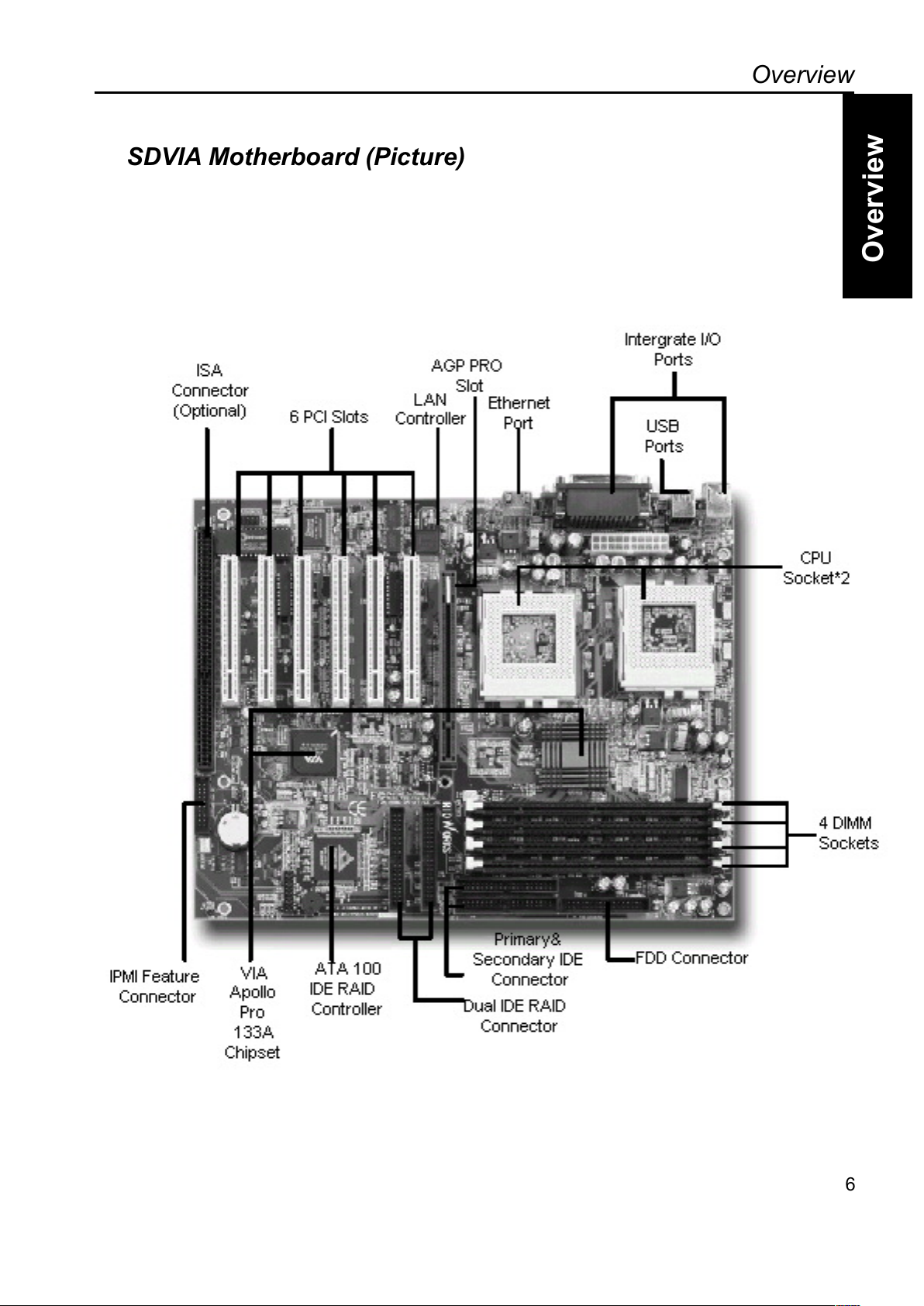
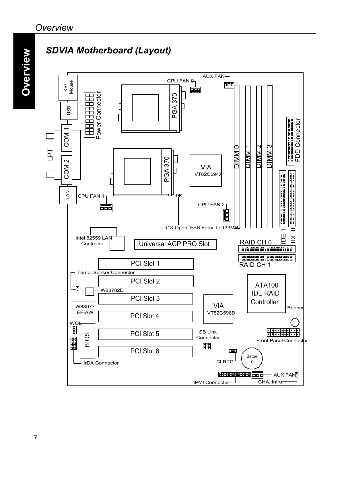
SDVIA Motherboard (Picture)
6
Page 10
Overview
Overview
SDVIA Motherboard (Layout)
7
PCI Slot 2
PCI Slot 3
PCI Slot 1
DIMM 1
DIMM 2
VIA
VT82C694X
KB/
Mouse
BIOS
Universal AGP PRO Slot
COM 2 COM 1
LPT
USB
PCI Slot 4
DIMM 3
VIA
VT82C596B
W83977
EF-AW
DIMM 0
ATA100
IDE RAID
Controller
PCI Slot 5
PCI Slot 6
LAN
Power Connector
J13-Open: FSB Force to 133MHz
CPU FAN 1
CPU FAN 2
FDD Connector
IDE 0
IDE 1
Intel 82559 LAN
Controller
W83782D
IrDA Connector
WOL
Beeper
Front Panel Connecto
r
SB Link
Connector
AUX FAN
CHA. Intru.
Temp. Sensor Connector
IPMI Connector
PGA 370
PGA 370
AUX FAN
CPU FAN 0
*=JJAH
O
CLRTC
RAID CH 0
RAID CH 1
Page 11
Overview
Overview
8
Note
If you are using a single processor on the PDVIA M/B, please insert the CPU in the CPU
slot #0.
Page 12
Hardware Installation
Overview
Hardware Installation
1-1
+D=FJAH
Hardware Installation
This chapter explains in detail the installation of the PDVIA with the processor and
other hardware connected to your system.
Installation Procedures
Installation is broken up into six major parts.
Step 1: Jumper setting
Step 2: Install memory (DIMM modules)
Step 3: Install CPU
Step 4: Attach cables to connectors
Step 5: Install expansion cards
Step 6: Power your computer
Warning
This motherboard contains sensitive electronic components that can be easily
damaged by static electricity. Follow the instructions carefully to ensure correc
t
installation and to avoid static damage.
Page 13
Hardware Installation
Overview
Hardware Installation
Step 1.
Jumper Setting
There are two jumpers you can use to change the setting on the motherboard.
Item Connectors Page
1 Clear Real Time Clock (RTC) RAM (CLRTC) 1-2
2 FSB Forces to 100/133 MHz 1-3
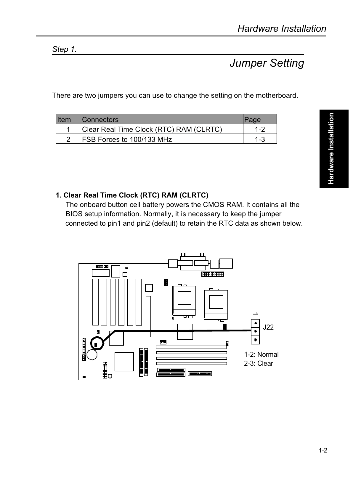
1. Clear Real Time Clock (RTC) RAM (CLRTC)
The onboard button cell battery powers the CMOS RAM. It contains all the
BIOS setup information. Normally, it is necessary to keep the jumper
connected to pin1 and pin2 (default) to retain the RTC data as shown below.
1-2
1
1-2: Normal
2-3: Clear
J22
Page 14
Hardware Installation
Overview
Hardware Installation
Note
Should you want to clear the RTC data:
(1) Turn off your computer
(2) Short pin2 and pin3 with jumper for two seconds
(3) Connect pin1 and pin2 with jumper
(4) Turn on your computer
(5) Hold down <Delete> during bootup and enter BIOS setup to re-enter user
preferences.
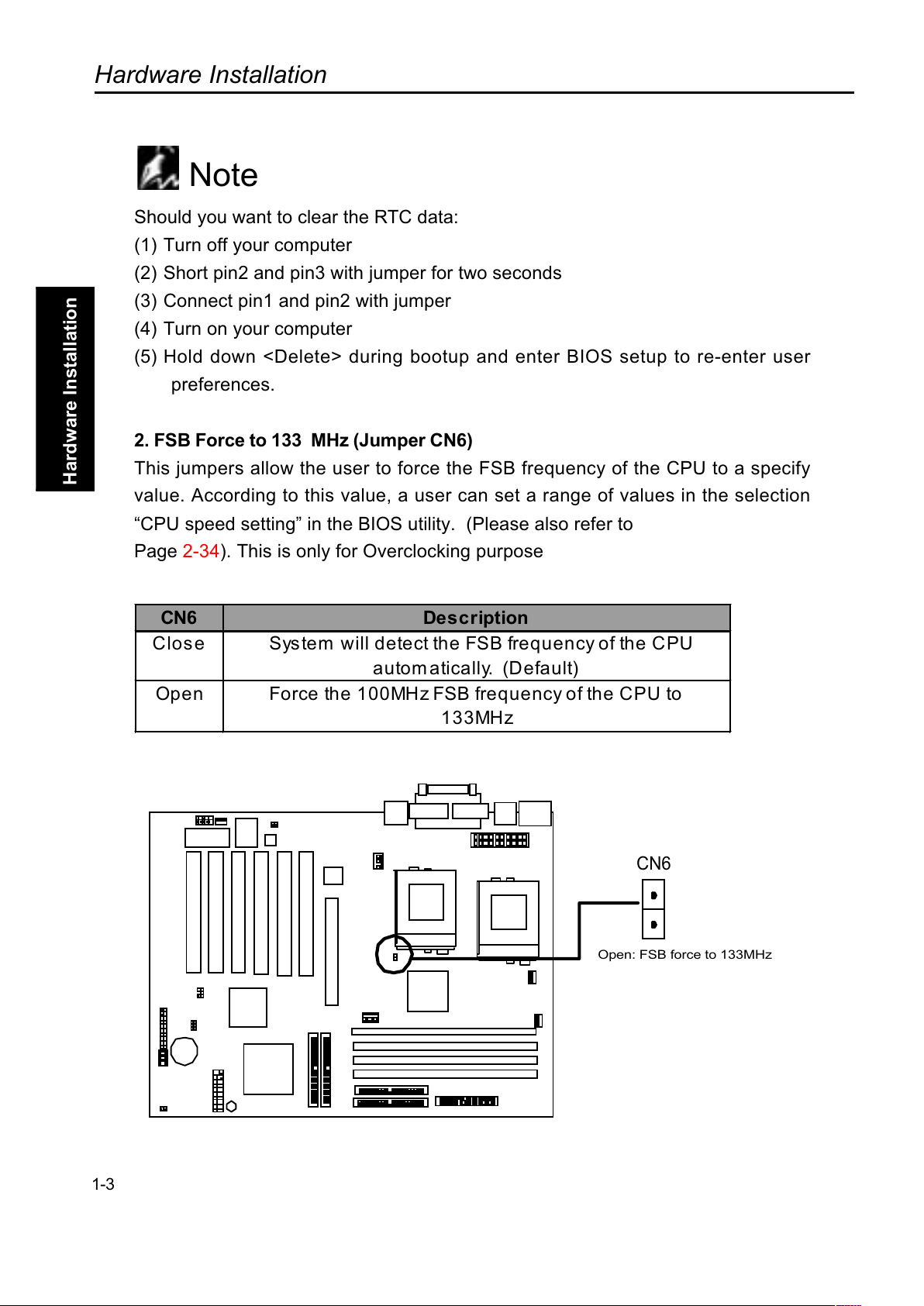
2. FSB Force to 133 MHz (Jumper CN6)
This jumpers allow the user to force the FSB frequency of the CPU to a specify
value. According to this value, a user can set a range of values in the selection
CPU speed setting in the BIOS utility. (Please also refer to
Page 2-34). This is only for Overclocking purpose
CN6 Description
Close System will detect the FSB frequency of the CPU
autom atically. (Default)
Open Force the 100MHz FSB frequency of the CPU to
133MHz
1-3
CN6
Open: FSB force to 133MHz
Page 15
Hardware Installation
Overview
Hardware Installation
1-4
Step 2.
Install M e m ory
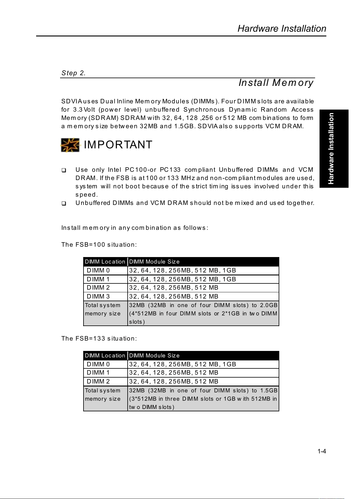
SDVIA uses Dual Inline Memory Modules (DIMMs). Four DIMM s lots are available
for 3.3 Volt (power level) unbuffered Synchronous Dynamic Random Access
Mem ory (SDRAM) SDRAM with 32, 64, 128 ,256 or 512 MB com binations to form
a m em ory s ize b etw ee n 32 MB an d 1 .5 GB. SD VIA als o s up p orts VCM D R AM.
IMPORTANT
!"
Use only Intel PC100-or PC133 com pliant Unbuffered DIMMs and VCM
D R AM. If the FSB is at 1 00 o r 13 3 MH z and n on -com plia n t mod ules are use d,
system will not boot because of the strict timing issues involved under this
speed.
!"
Unbuffered DIMMs and VCM DRAM should not be mixed and used together.
Install mem ory in any combination as follows:
The FSB=100 situation:
DIMM Location DIMM Module Siz e
DIMM 0 32, 64, 128, 256MB, 512 MB, 1GB
DIMM 1 32, 64, 128, 256MB, 512 MB, 1GB
DIMM 2 32, 64, 128, 256MB, 512 MB
DIMM 3 32, 64, 128, 256MB, 512 MB
Total system
memo r y s iz e
32MB (32MB in one of four DIM M slots) to 2.0GB
(4*512MB in four DIMM slots or 2*1GB in tw o DIMM
slots)
The FSB=133 situation:
DIMM Location DIMM Module Siz e
DIMM 0 32, 64, 128, 256MB, 512 MB, 1GB
DIMM 1 32, 64, 128, 256MB, 512 MB
DIMM 2 32, 64, 128, 256MB, 512 MB
Total system
memo r y s iz e
32MB (32MB in one of four DIMM slots) to 1.5GB
(3*512MB in three DIMM slots or 1GB w ith 512MB in
tw o DIMM slots )
Page 16
Hardware Installation
Overview
Hardware Installation
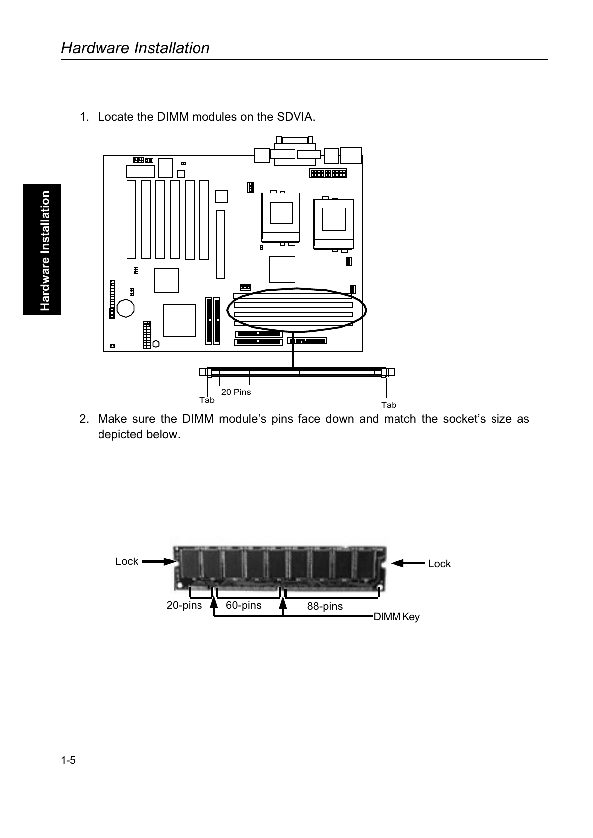
1. Locate the DIMM modules on the SDVIA.
2. Make sure the DIMM modules pins face down and match the sockets size as
depicted below.
1-5
Lock
Lock
20-pins 60-pins
88-pins
DIMM Key
20 Pins
Tab
Tab
Page 17
Hardware Installation
Overview
Hardware Installation
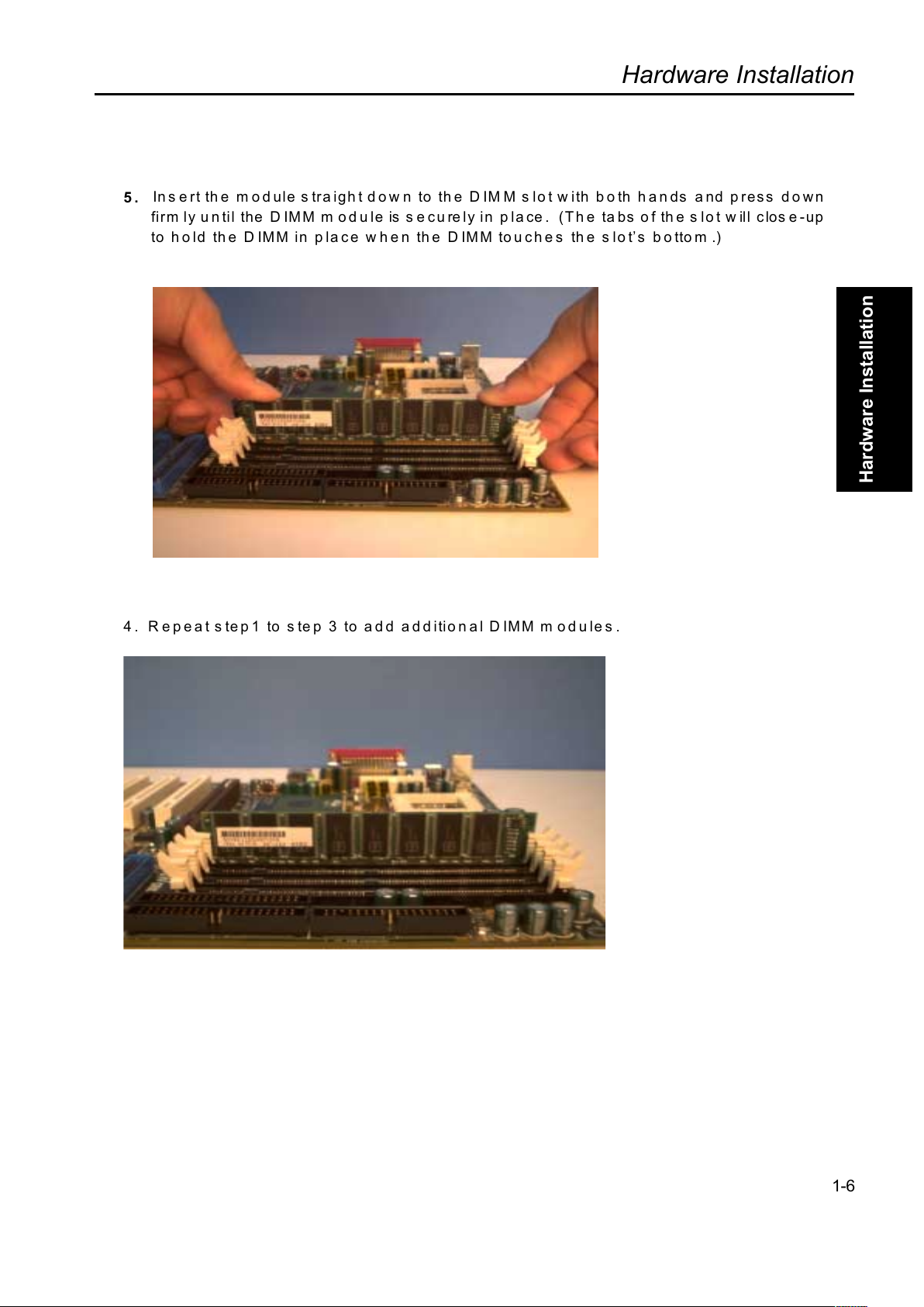
5.
Insert the module straight down to the DIMM slot with both hands and press down
firm ly until the DIMM m odule is securely in place. (The tabs of the slot will close-up
to hold the DIMM in place when the DIMM touches the slots bottom .)
4. Repeat step1 to step 3 to add additional DIMM m odules.
1-6
Page 18
Hardware Installation
Overview
Hardware Installation
Step 3
Install CPU
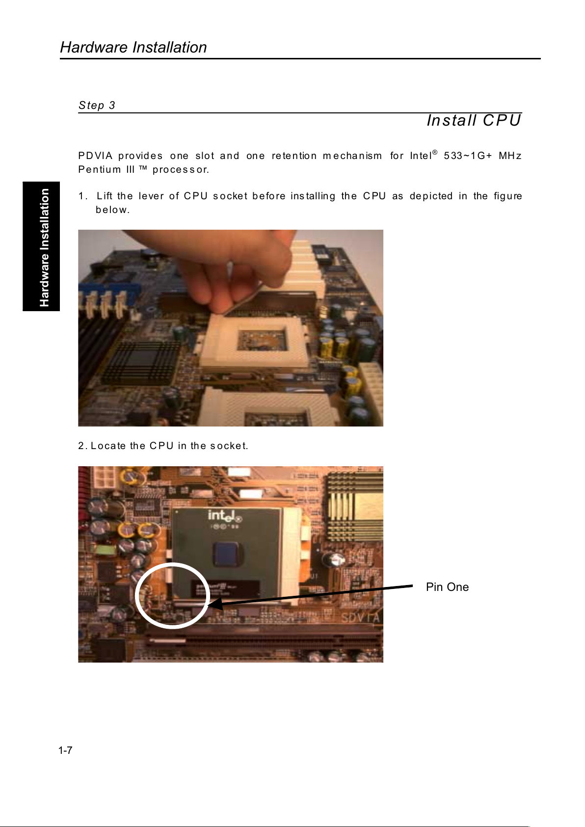
PDVIA provides one slot and one retention mechanism for Intel® 533~1G+ MHz
Pe ntiu m III p ro ce s s or.
1. Lift th e le ve r of C P U s o cket be fo re ins talling th e C PU as de p icted in the figu re
below.
2. L oca te th e C PU in th e s oc ke t.
1-7
Pin One
Page 19
Hardware Installation
Overview
Hardware Installation
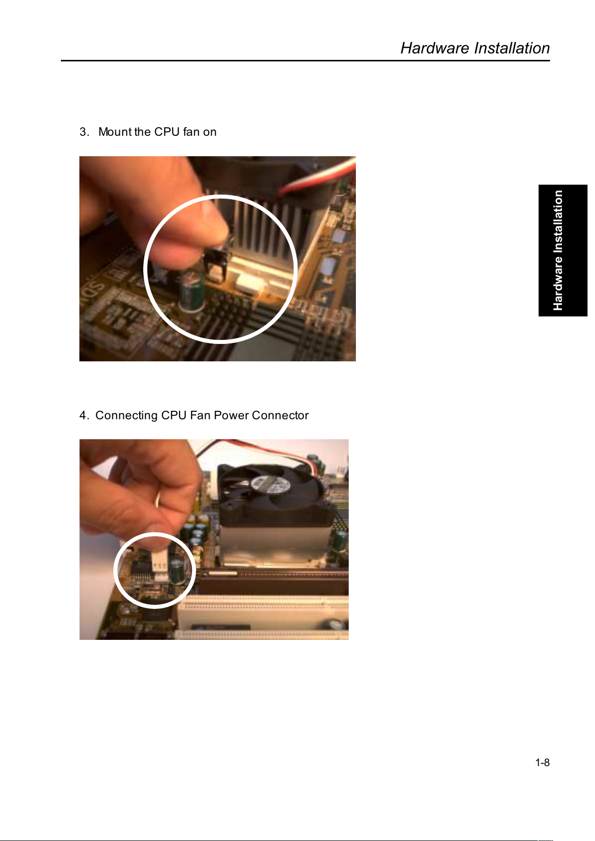
3. Mount the CPU fan on
4. Connecting CPU Fan Power Connector
1-8
Page 20

Hardware Installation
Overview
Hardware Installation
1-9
(This Page Intentionally Left Blank for Notes)
Page 21
Hardware Installation
Overview
Hardware Installation
1-10
Step 4.
Attach Cable to Connectors
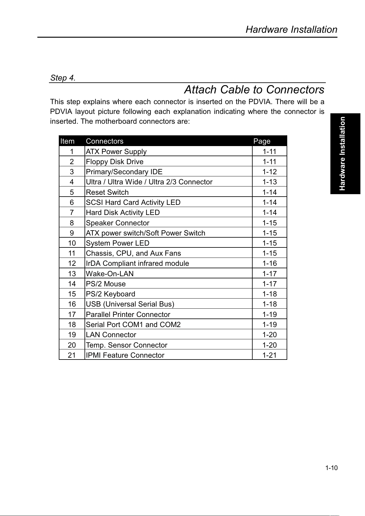
This step explains where each connector is inserted on the PDVIA. There will be a
PDVIA layout picture following each explanation indicating where the connector is
inserted. The motherboard connectors are:
Item Connectors Page
1 ATX Power Supply 1-11
2 Floppy Disk Drive 1-11
3 Primary/Secondary IDE 1-12
4 Ultra / Ultra Wide / Ultra 2/3 Connector 1-13
5 Reset Switch 1-14
6 SCSI Hard Card Activity LED 1-14
7 Hard Disk Activity LED 1-14
8 Speaker Connector 1-15
9 ATX power switch/Soft Power Switch 1-15
10 System Power LED 1-15
11 Chassis, CPU, and Aux Fans 1-15
12 IrDA Compliant infrared module 1-16
13 Wake-On-LAN 1-17
14 PS/2 Mouse 1-17
15 PS/2 Keyboard 1-18
16 USB (Universal Serial Bus) 1-18
17 Parallel Printer Connector 1-19
18 Serial Port COM1 and COM2 1-19
19 LAN Connector 1-20
20 Temp. Sensor Connector 1-20
21 IPMI Feature Connector 1-21
Page 22
Hardware Installation
Overview
Hardware Installation
IMPORTANT
Ribbon cables should always be connected with the red stripe on the Pin 1 side of the
connector. IDE ribbon cable must be less than 46cm (18inches), with the second drive
connector no more than 15cm (6 inches) from the first connector.
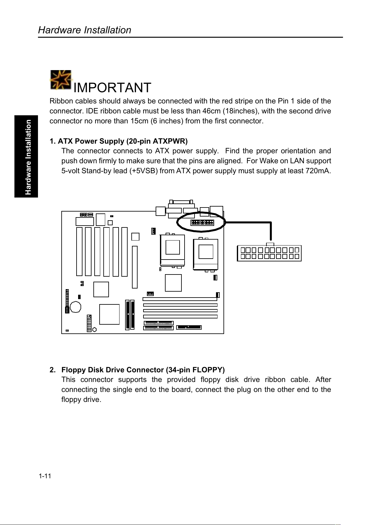
1. ATX Power Supply (20-pin ATXPWR)
The connector connects to ATX power supply. Find the proper orientation and
push down firmly to make sure that the pins are aligned. For Wake on LAN support
5-volt Stand-by lead (+5VSB) from ATX power supply must supply at least 720mA.
2. Floppy Disk Drive Connector (34-pin FLOPPY)
This connector supports the provided floppy disk drive ribbon cable. Afte
r
connecting the single end to the board, connect the plug on the other end to the
floppy drive.
1-11
Page 23
Hardware Installation
Overview
Hardware Installation
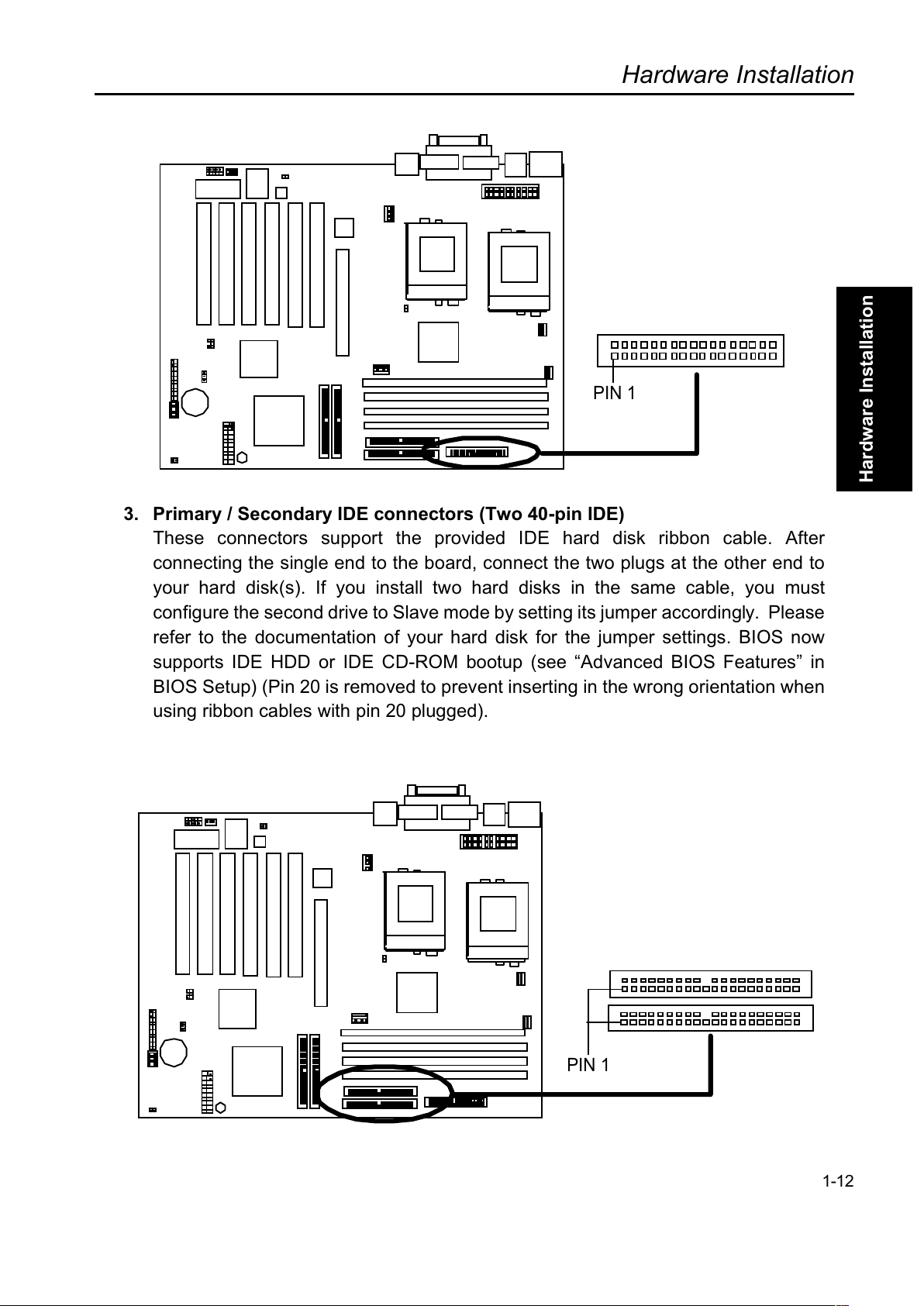
3. Primary / Secondary IDE connectors (Two 40-pin IDE)
These connectors support the provided IDE hard disk ribbon cable. Afte
r
connecting the single end to the board, connect the two plugs at the other end to
your hard disk(s). If you install two hard disks in the same cable, you must
configure the second drive to Slave mode by setting its jumper accordingly. Please
refer to the documentation of your hard disk for the jumper settings. BIOS now
supports IDE HDD or IDE CD-ROM bootup (see Advanced BIOS Features in
BIOS Setup) (Pin 20 is removed to prevent inserting in the wrong orientation when
using ribbon cables with pin 20 plugged).
1-12
PIN 1
PIN 1
Page 24
Hardware Installation
Overview
Hardware Installation
TIP
You may configure two hard disks to be both Masters using one ribbon cable on the
primary IDE connector and another ribbon cable on the secondary IDE connector.
IMPORTANT
If you want to have ATA/66 feature, you should use the ATA/66 cable that is different
from ATA/33 cable.
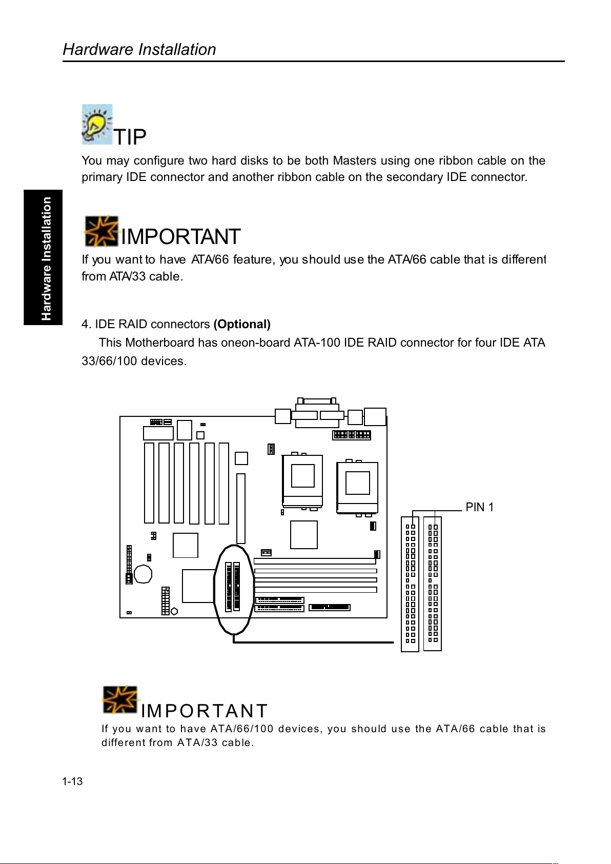
4. IDE RAID connectors (Optional)
This Motherboard has oneon-board ATA-100 IDE RAID connector for four IDE ATA
33/66/100 devices.
IMPORTANT
If you want to have ATA/66/100 devices, you should use the ATA/66 cable that is
different from A T A/33 cable.
1-13
PIN 1
Page 25
Hardware Installation
Overview
Hardware Installation
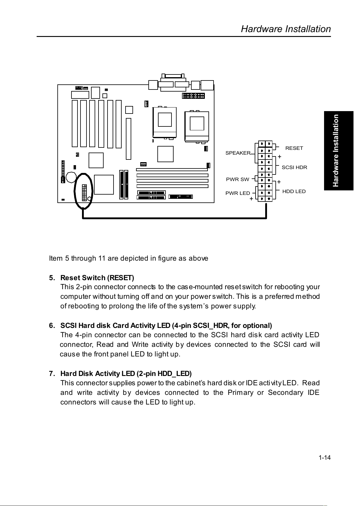
Item 5 through 11 are depicted in figure as above
5. Reset Switch (RESET)
This 2-pin connector connects to the case-mounted reset switch for rebooting you
r
computer without turning off and on your power switch. This is a preferred method
of rebooting to prolong the life of the systems power supply.
6. SCSI Hard disk Card Activity LED (4-pin SCSI_HDR, for optional)
The 4-pin connector can be connected to the SCSI hard disk card activity LED
connector, Read and Write activity by devices connected to the SCSI card will
caus e the front panel LED to light up.
7. Hard Disk Activity LED (2 -pin HDD_ LED)
This connector supplies power to the cabinets hard disk or IDE activity LED. Read
and write activity by devices connected to the Primary or Secondary IDE
connectors will cause the LED to light up.
1-14
+
+
+
PWR LED
PWR SW
SPEAKER
RESET
SCSI HDR
HDD LED
Page 26
Hardware Installation
Overview
Hardware Installation
8. Speaker Connector (4-pin SPEAKER)
There is one jumper cap over pin1 and pin2 (default setting) for internal buzzer. I
f
you want to use external case-mounted speaker instead of internal buzzer, remove
jumper cap and connect speaker wire to the 4-pin connector.
9. ATX Power Switch / Soft Power Switch (2-pin PWR_SW)
A momentary switch connected to these connector controls the system power.
Pressing the button once will switch the system between ON and SLEEP. Pressing
the switch while in the ON mode for more than 4 seconds will turn the system off.
The system power LED shows the status of the systems power.
10.System Power LED (3-pin PWR_LED)
This 3-pin connector connects the system power LED, which lights up when the
system is powered on and blinks when it is in sleep mode.
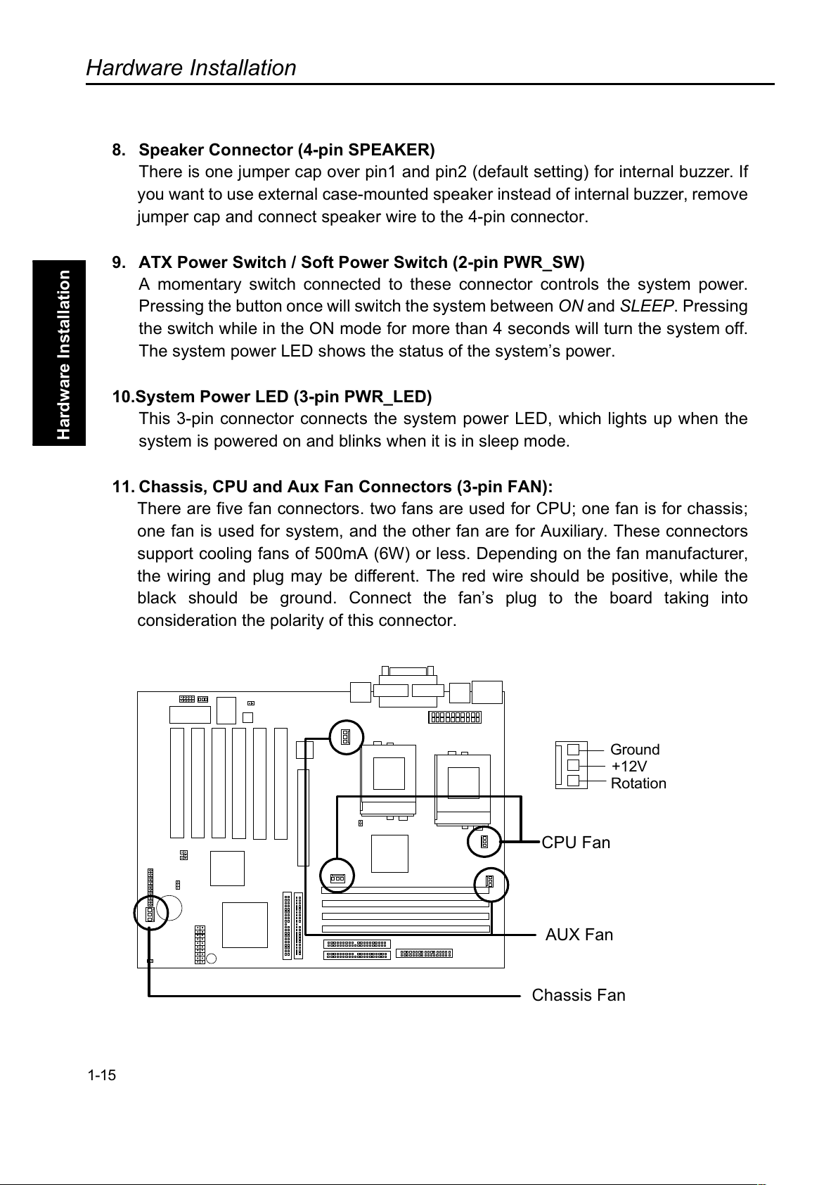
11. Chassis, CPU and Aux Fan Connectors (3-pin FAN):
There are five fan connectors. two fans are used for CPU; one fan is for chassis;
one fan is used for system, and the other fan are for Auxiliary. These connectors
support cooling fans of 500mA (6W) or less. Depending on the fan manufacturer,
the wiring and plug may be different. The red wire should be positive, while the
black should be ground. Connect the fans plug to the board taking into
consideration the polarity of this connector.
1-15
AUX Fan
CPU Fan
Chassis Fan
Ground
+12V
Rotation
Page 27
Hardware Installation
Overview
Hardware Installation
NOTE
The Rotation signal has to be used with fan specially designed with rotation signal.
WARNING
The CPU and/or motherboard will overheat if there is not enough airflow across the
CPU and onboard heatsink. Damage may occur to the motherboard and/or the
CPU fan if these pins are incorrectly used. These are not jumpers, do not place
jumper caps over these pins.
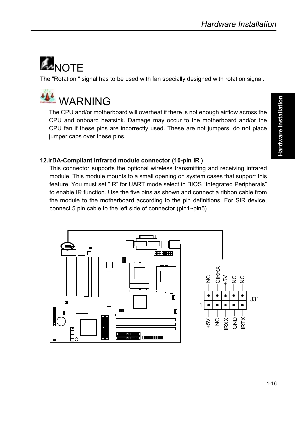
12.IrDA-Compliant infrared module connector (10-pin IR )
This connector supports the optional wireless transmitting and receiving infrared
module. This module mounts to a small opening on system cases that support this
feature. You must set IR for UART mode select in BIOS Integrated Peripherals
to enable IR function. Use the five pins as shown and connect a ribbon cable from
the module to the motherboard according to the pin definitions. For SIR device,
connect 5 pin cable to the left side of connector (pin1~pin5).
1-16
J31
1
NC
CIRRX
+5V
NC
NC
NC
+5V
IRXX
GND
IRTX
Page 28
Hardware Installation
Overview
Hardware Installation
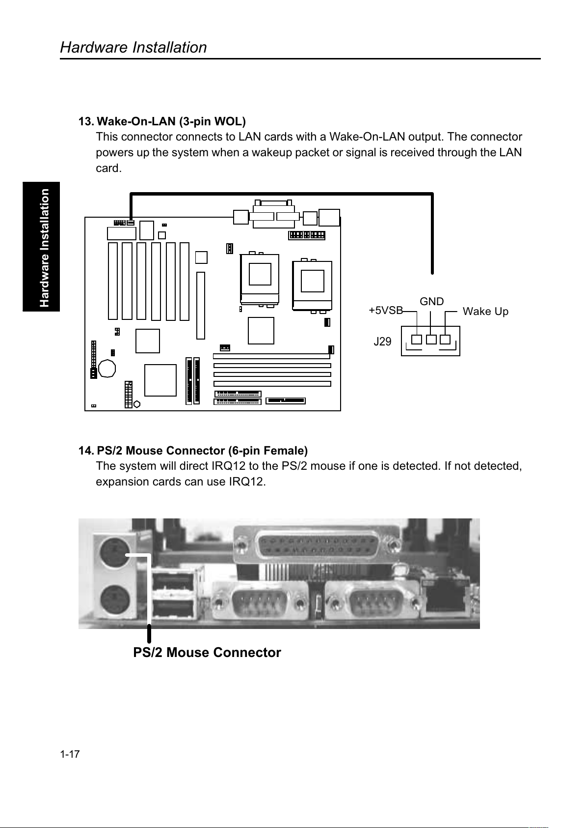
13. Wake-On-LAN (3-pin WOL)
This connector connects to LAN cards with a Wake-On-LAN output. The connecto
r
powers up the system when a wakeup packet or signal is received through the LAN
card.
14. PS/2 Mouse Connector (6-pin Female)
The system will direct IRQ12 to the PS/2 mouse if one is detected. If not detected,
expansion cards can use IRQ12.
PS/2 Mouse Connector
1-17
J29
+5VSB
GND
Wake Up
Page 29
Hardware Installation
Overview
Hardware Installation
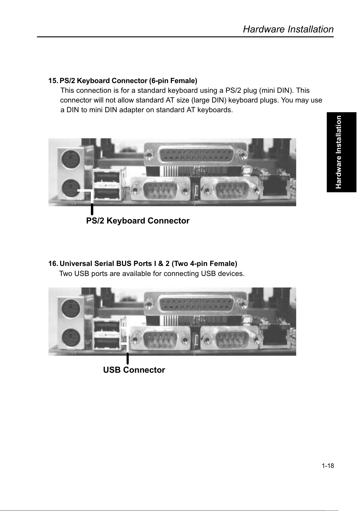
15. PS/2 Keyboard Connector (6-pin Female)
This connection is for a standard keyboard using a PS/2 plug (mini DIN). This
connector will not allow standard AT size (large DIN) keyboard plugs. You may use
a DIN to mini DIN adapter on standard AT keyboards.
PS/2 Keyboard Connector
16. Universal Serial BUS Ports I & 2 (Two 4-pin Female)
Two USB ports are available for connecting USB devices.
USB Connector
1-18
Page 30
Hardware Installation
Overview
Hardware Installation
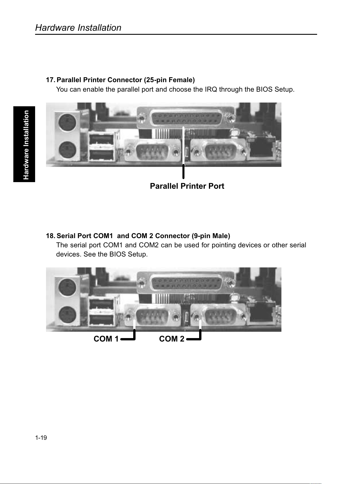
17. Parallel Printer Connector (25-pin Female)
You can enable the parallel port and choose the IRQ through the BIOS Setup.
Parallel Printer Port
18. Serial Port COM1 and COM 2 Connector (9-pin Male)
The serial port COM1 and COM2 can be used for pointing devices or other serial
devices. See the BIOS Setup.
COM 1 COM 2
1-19
Page 31
Hardware Installation
Overview
Hardware Installation
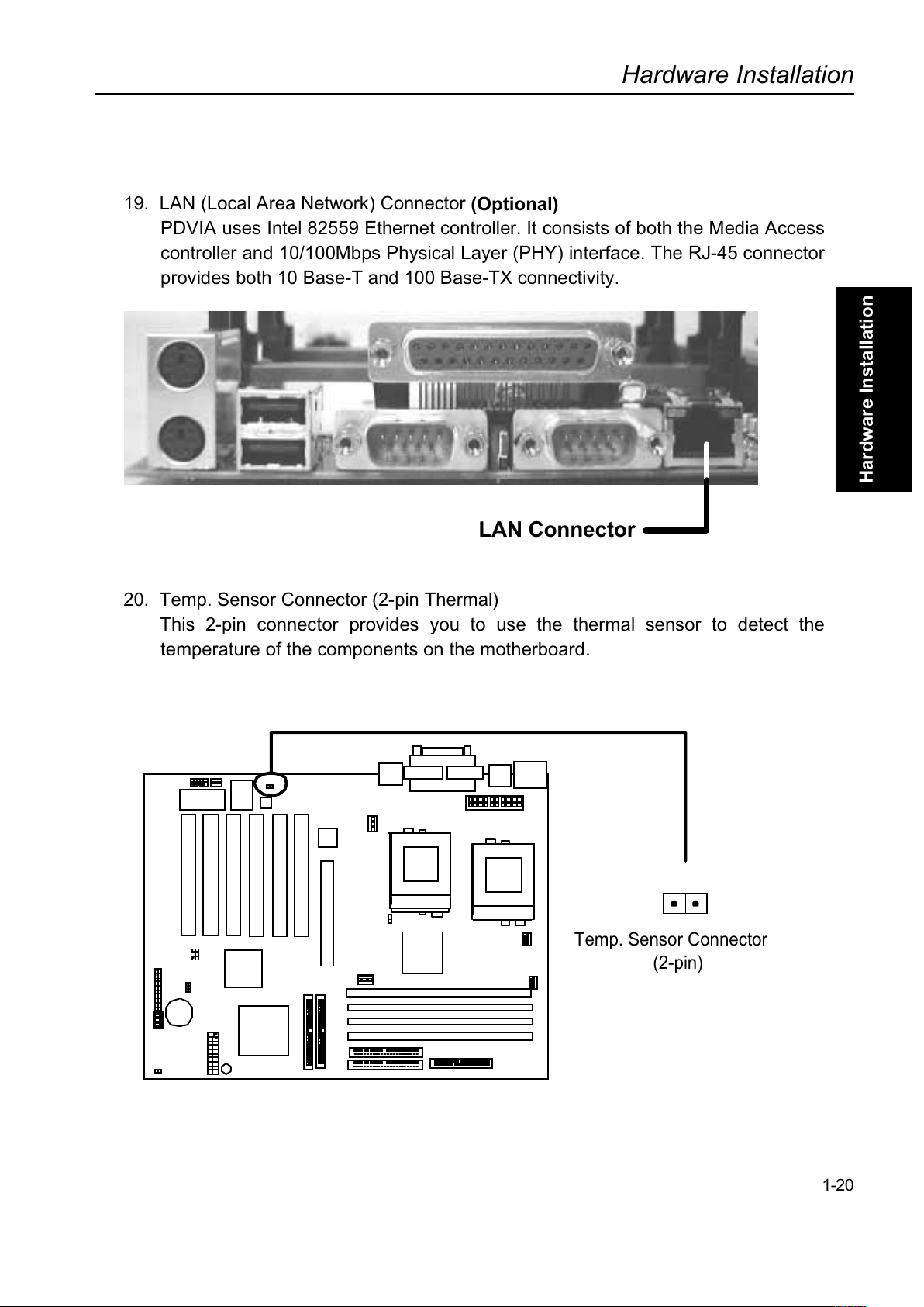
19. LAN (Local Area Network) Connector
(Optional)
PDVIA uses Intel 82559 Ethernet controller. It consists of both the Media Access
controller and 10/100Mbps Physical Layer (PHY) interface. The RJ-45 connector
provides both 10 Base-T and 100 Base-TX connectivity.
LAN Connector
20. Temp. Sensor Connector (2-pin Thermal)
This 2-pin connector provides you to use the thermal sensor to detect the
temperature of the components on the motherboard.
1-20
Temp. Sensor Connector
(2-pin)
Page 32
Hardware Installation
Overview
Hardware Installation
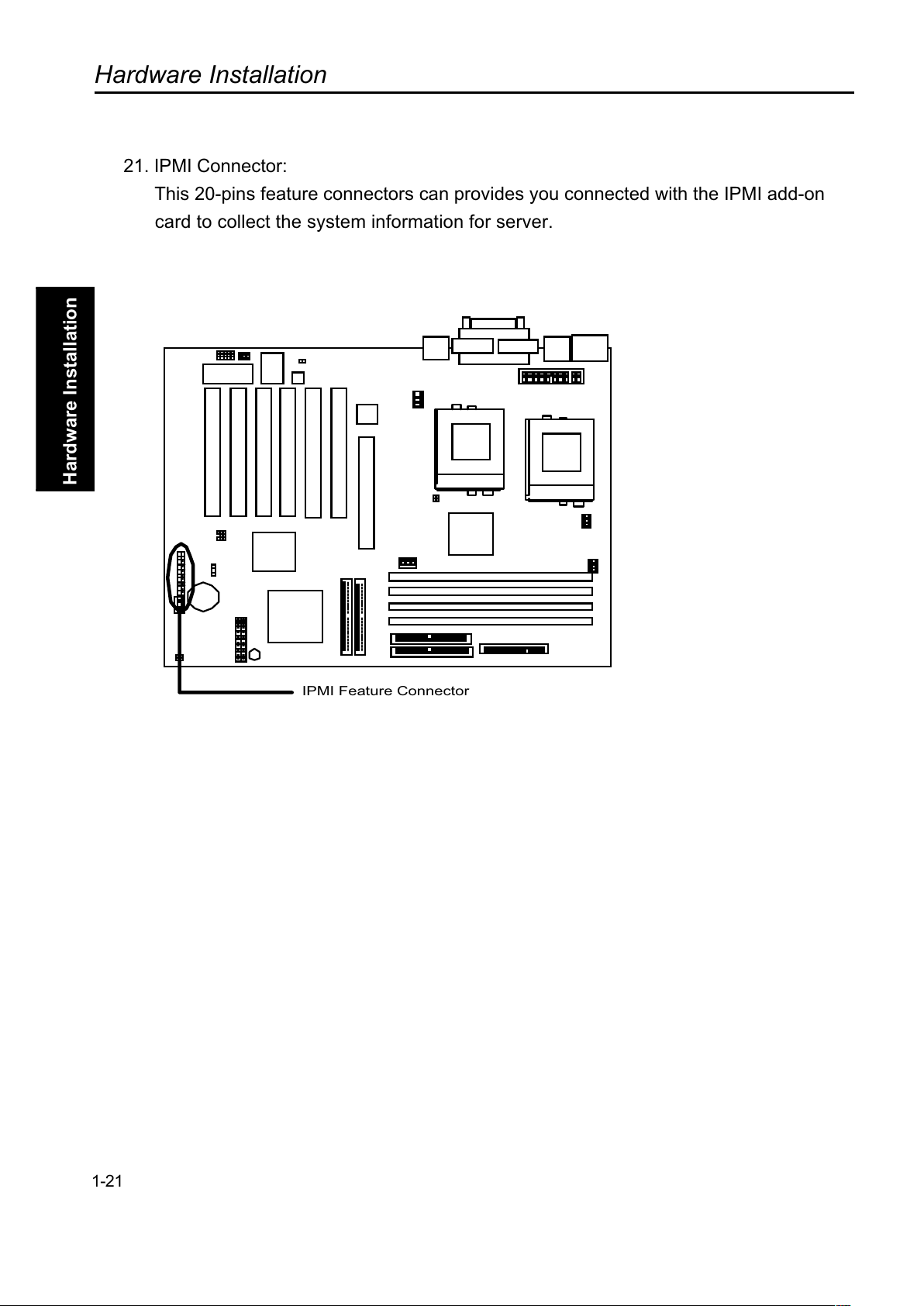
21. IPMI Connector:
This 20-pins feature connectors can provides you connected with the IPMI add-on
card to collect the system information for server.
1-21
IPMI Feature Connector
Page 33

Hardware Installation
Overview
Hardware Installation
(This page left blank intentionally for notes)
1-22
Page 34
Hardware Installation
Overview
Hardware Installation
Step 5.
Install Expansion Cards
WARNING
Power off your power supply completely when adding or removing any expansion
cards or other system components. Failure to do so may cause severe damage to both
your motherboard and expansion cards.
1. Expansion Card Installation Procedure
1.1 Read the documentation for your expansion card and make any necessar
y
hardware or software setting changes, such as jumpers.
1.2 Remove the bracket plate on the slot you intend to use. Keep the bracket fo
r
possible future use.
1.3 Carefully align the cards connectors and press firmly.
1.4 Secure the card on the slot with the screw you removed above.
1.5 Jump to step 6 to finish installation, then set the IRQ and DMA as follows.
2. Assigning IRQs for PCI Expansion Cards
An IRQ number is automatically assigned to PCI expansion cards. In the PCI
bus design, the BIOS automatically assigns an IRQ to a PCI slot that contains a card
requiring an IRQ. To install a PCI card, you need to set the INT (interrupt) assignment.
Since all the PCI slots on this motherboard use an INTA #, set the jumpers on your PCI
cards to INTA.
1-23
Page 35

Hardware Installation
Overview
Hardware Installation
Step 6.
Powering on Your Computer
1. Be sure that all switches are off (in some systems, marked with O).
2. After finishing all jumper settings and connections, close the system case
cover.
3. Connect the power supply cord into the power supply located on the back o
f
your system case.
4. Connect the power cord into a power outlet that is equipped with a surge
protector.
5. You may then turn on your devices in the following order:
#" Your monitor
#" External SCSI devices (starting with the last device on the
chain)
#" Your system power.
For ATX power supplies, you need to switch on the power supply as well as
press the ATX power switch on the front of the case.
6. The power LED on the front panel of the system case will light up. For ATX
power supplies, the system LED will light up when the ATX power switch is
pressed. The monitor LED may light up after the systems LED if it complies
with green standards or if it has a power standby feature. The system will
then run power-on tests. While the tests are running, additional messages
will appear on the screen. If you do not see anything within 30 seconds
from the time you turn on the power, the system may have failed a
power-on test. Recheck your jumper settings and connections or call your
retailer for assistance.
1-24
Page 36
Hardware Installation
Overview
Hardware Installation
7. During power-on, hold down <Delete> to enter BIOS setup. Follow the
instructions in the next chapter, BIOS Setup.
Note
Powering Off your computer
You have to first exit or shut down your operating system before switching off the
power switch. For ATX power supplies, you can press the ATX power switch afte
r
exiting or shutting down your operating system.
1-25
Page 37

Hardware Installation
Overview
Hardware Installation
(This page left blank intentionally for notes)
1-26
Page 38
BIOS Setup
BIOS Setup
+D=FJAH
BIOS Setup
This chapter discusses the Award Setup program built into the ROM BIOS. The
Setup program allows users modifying the basic system configurations according to
their requirements. This special information is then stored in battery-backed RAM so
that it retains the Setup information when the power is turned off.
The AwardBIOS installed in your computer systems ROM (Read Only Memory) is a
custom version of an industry standard BIOS. The BIOS provides critical low-level
support for standard devices such as disk drives and serial and parallel ports.
The AwardBIOS has been customized by adding important, but non-standard,
features such as password protection as well as special support for detailed fine-tuning
of the chipset controlling the entire system.
The rest of this chapter is intended to guide you through the process of configuring
your system using Setup.
Note
If your BIOS setup screen is differ from this manual, please visit our website:
www.rioworks.com/downlaod/
for get newest BIOS setup description.
Starting BIOS Setup
The AwardBIOS is immediately activated when you power on the computer every
time. The BIOS reads the system information contained in the CMOS and begins the
process of checking out the system and configuring it. After finishing configuring the
whole system, then BIOS will continue to seek an operating system on one of the disks
launch then turn control over to the operating system.
While the BIOS is in control, the Setup program can be activated in one of two ways:
1. By pressing the <Del> key when the following message appears briefly at
the bottom of the screen during the POST (Power On Self-Test).
Press DEL to enter SETUP.
2-1
Page 39
BIOS Setup
BIOS Setup
2. By pressing <Del>immediately after switching the system on.
If the message disappears before you respond and you still wish to enter Setup
Program, restart the system from state On to state Off by pressing the "RESET"
button on the system case. You may also restart the system by simultaneousl
y
pressing <Ctrl>, <Alt>, and <Delete> keys. If you do not press the keys at the correc
t
time and the system does not boot as well, an error message will be displayed and you
will again be asked to...
PRESS F1 TO CONTINUE, DEL TO ENTER SETUP
Using Setup
In general, you use the arrow keys to highlight items, press <Enter> to select, use the
PageUp and PageDown keys to change entries, press <F1> for help and press <Esc>
to quit. The following table provides more details about how to navigate in the Setup
program using the keyboard.
Key Function
Up Arrow Move to the previous item
Down Arrow Move to the next item
Left Arrow Move to the item on the left (menu bar)
Right Arrow Move to the item on the right (menu bar)
Esc key
Main Menu Quit and not save changes into CMOS
Status Page Setup Menu and Option Page Setup
Menu Exit current page and return to Main Menu
PgUp Key Increase The numeric value or make changes
PgDn Key Decrease The numeric value or make changes
+ Key Increase The numeric value or make changes
- Key Decrease The numeric value or make changes
F1 key
General help on Setup navigation keys. Press F1 to pop
up a small help window that describes the appropriate
keys to use and the possible selections for the
highlighted item. To exit the Help Window press <Esc>
or the F1 key again.
F5 key
Load previous values from CMOS
F6 key
Load previous values from CMOS
F7 key
Load the fail-safe defaults from BIOS default table
F10 key
Save all the CMOS changes and exit
2-2
Page 40
BIOS Setup
BIOS Setup
Navigating through the menu bar
Use the left and right arrow keys to navigate the menu you want to be in.
To display a sub menu
Use the arrow keys to move the cursor to the sub menu you want. Then press <Enter>
A
# pointer marks all sub menus.
In Case of Problems
If, after making and saving system changes with Setup, you discover that your
computer no longer is able to boot, the Award BIOS supports an override to the
CMOS setting, which resets your system to its defaults. The other way is clear the
present CMOS information. (Refer to the jumper setting J22 on the page1-2).
The best advice is to only alter settings, which you thoroughly understand. In the end,
we strongly recommend that you avoid making any changes to the chipset defaults.
These defaults have been carefully chosen by both Award and RIOWORKS
TM
to
provide the maximum performance and reliability of the system. Even a sight change
to the chipset setup may also cause potential and unpredictable failure to the system.
2-3
Page 41
BIOS Setup
BIOS Setup
Section 1
Setup Items
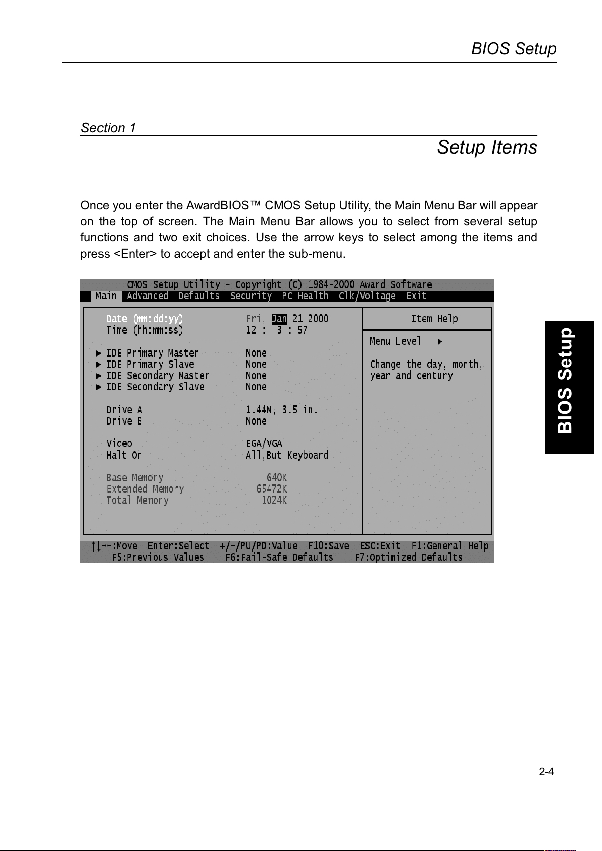
Once you enter the AwardBIOS CMOS Setup Utility, the Main Menu Bar will appea
r
on the top of screen. The Main Menu Bar allows you to select from several setup
functions and two exit choices. Use the arrow keys to select among the items and
press <Enter> to accept and enter the sub-menu.
2-4
Page 42
BIOS Setup
BIOS Setup
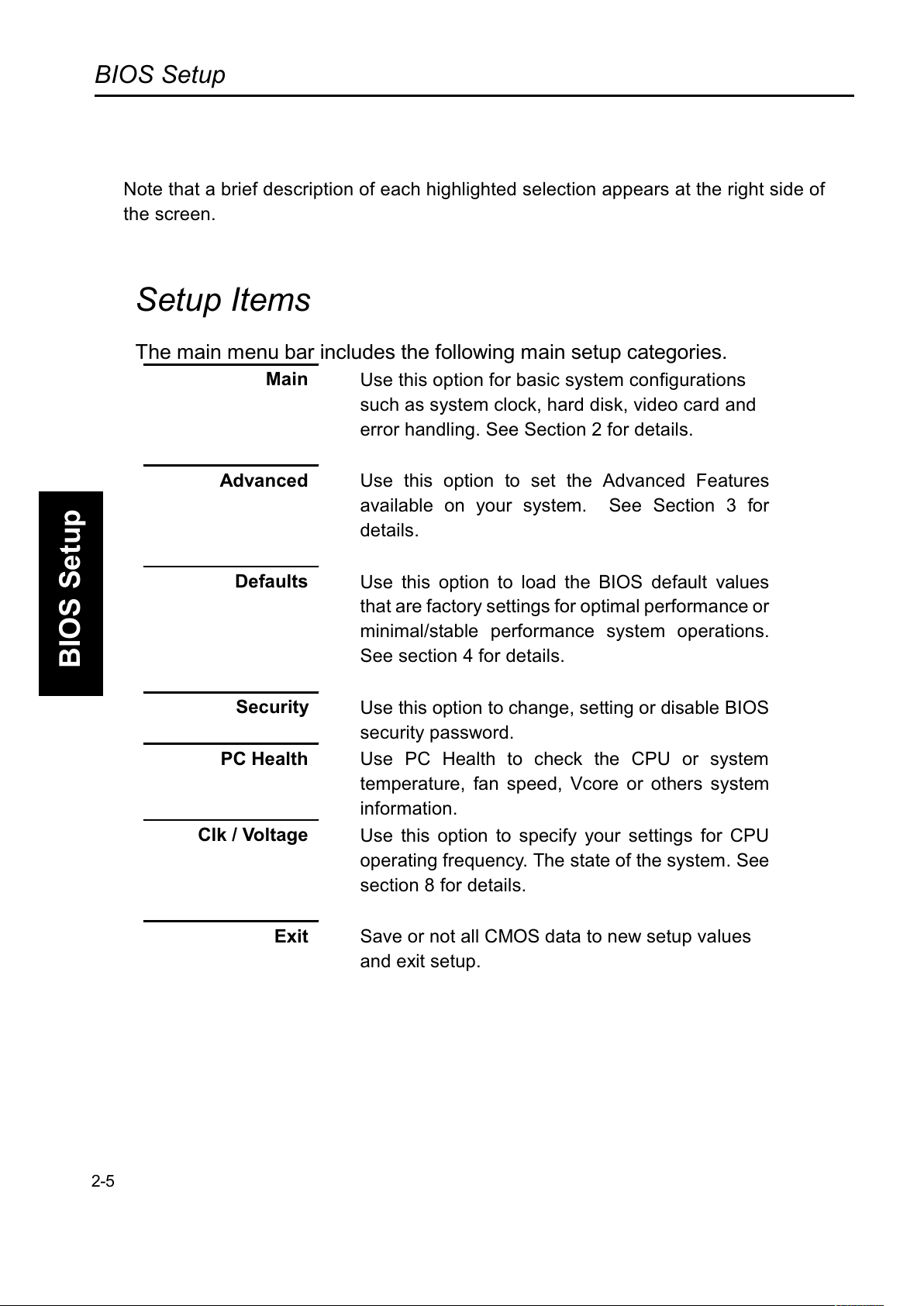
Note that a brief description of each highlighted selection appears at the right side of
the screen.
Setup Items
The main menu bar includes the following main setup categories.
Main
Use this option for basic system configurations
such as system clock, hard disk, video card and
error handling. See Section 2 for details.
Advanced
Use this option to set the Advanced Features
available on your system. See Section 3 for
details.
Defaults
Use this option to load the BIOS default values
that are factory settings for optimal performance or
minimal/stable performance system operations.
See section 4 for details.
Security
Use this option to change, setting or disable BIOS
security password.
PC Health
Use PC Health to check the CPU or system
temperature, fan speed, Vcore or others system
information.
Clk / Voltage
Use this option to specify your settings for CPU
operating frequency. The state of the system. See
section 8 for details.
Exit
Save or not all CMOS data to new setup values
and exit setup.
2-5
Page 43
BIOS Setup
BIOS Setup
Section 2
Main Setup
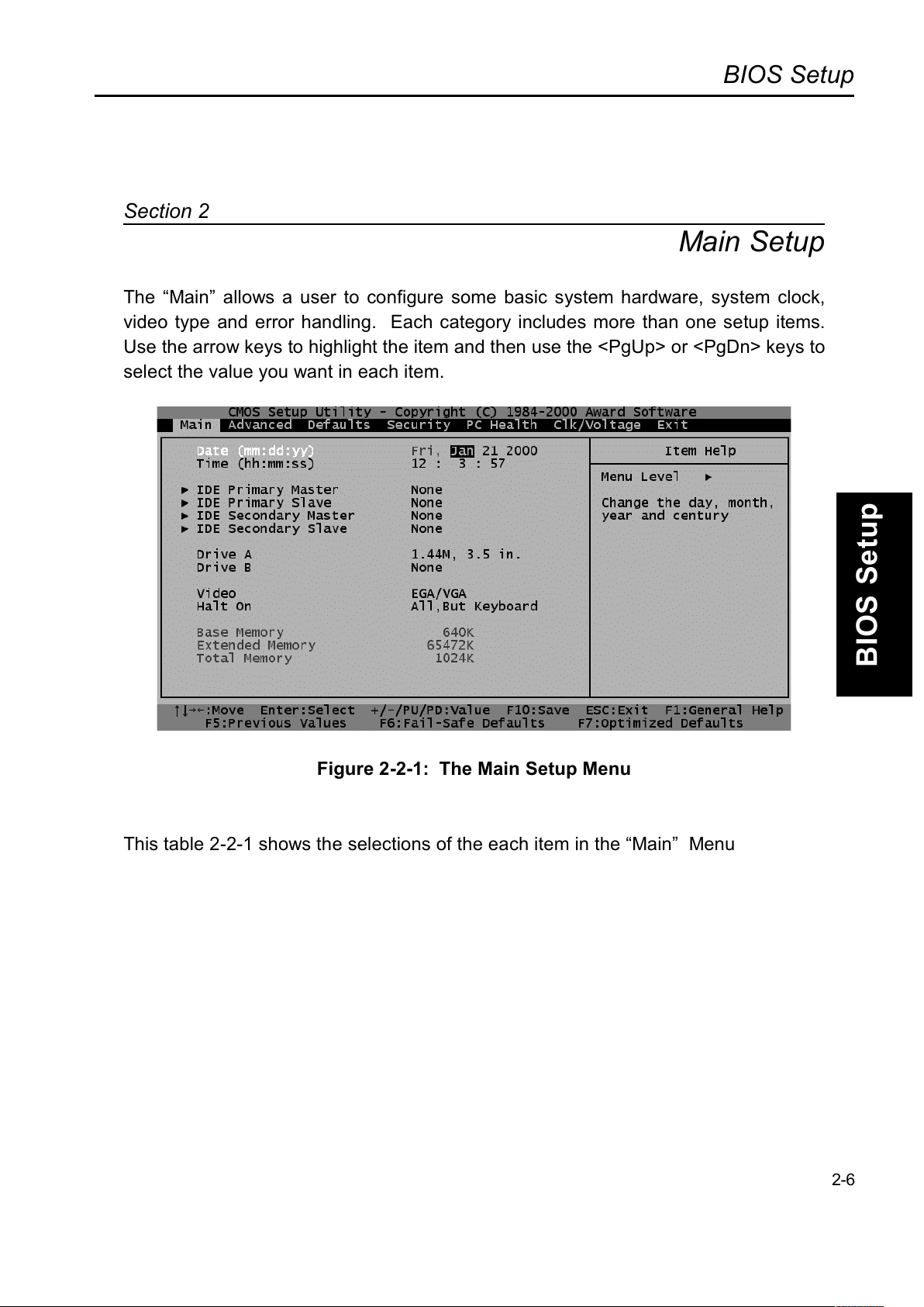
The Main allows a user to configure some basic system hardware, system clock,
video type and error handling. Each category includes more than one setup items.
Use the arrow keys to highlight the item and then use the <PgUp> or <PgDn> keys to
select the value you want in each item.
Figure 2-2-1: The Main Setup Menu
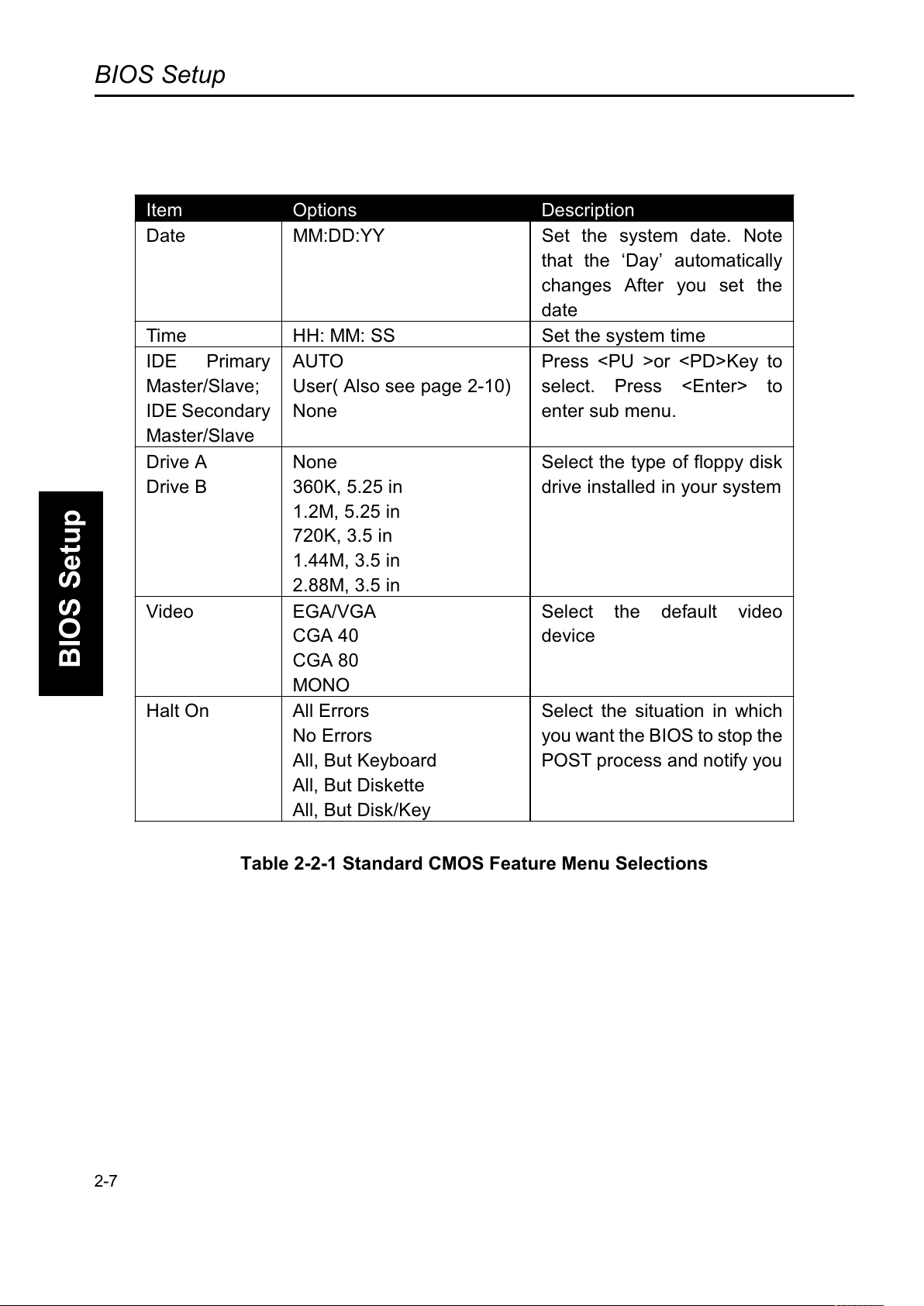
This table 2-2-1 shows the selections of the each item in the Main Menu
2-6
Page 44
BIOS Setup
BIOS Setup
Item Options Description
Date MM:DD:YY Set the system date. Note
that the Day automatically
changes After you set the
date
Time HH: MM: SS Set the system time
IDE Primary
Master/Slave;
IDE Secondary
Master/Slave
AUTO
User( Also see page 2-10)
None
Press <PU >or <PD>Key to
select. Press <Enter> to
enter sub menu.
Drive A
Drive B
None
360K, 5.25 in
1.2M, 5.25 in
720K, 3.5 in
1.44M, 3.5 in
2.88M, 3.5 in
Select the type of floppy disk
drive installed in your system
Video EGA/VGA
CGA 40
CGA 80
MONO
Select the default video
device
Halt On All Errors
No Errors
All, But Keyboard
All, But Diskette
All, But Disk/Key
Select the situation in which
you want the BIOS to stop the
POST process and notify you
Table 2-2-1 Standard CMOS Feature Menu Selections
2-7
Page 45
BIOS Setup
BIOS Setup
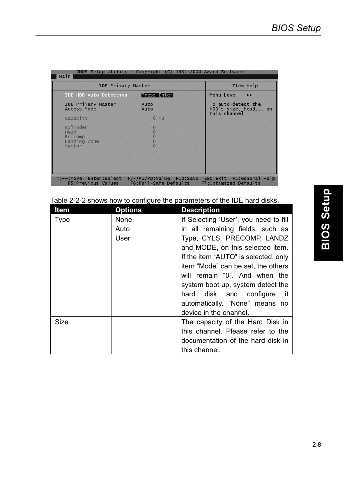
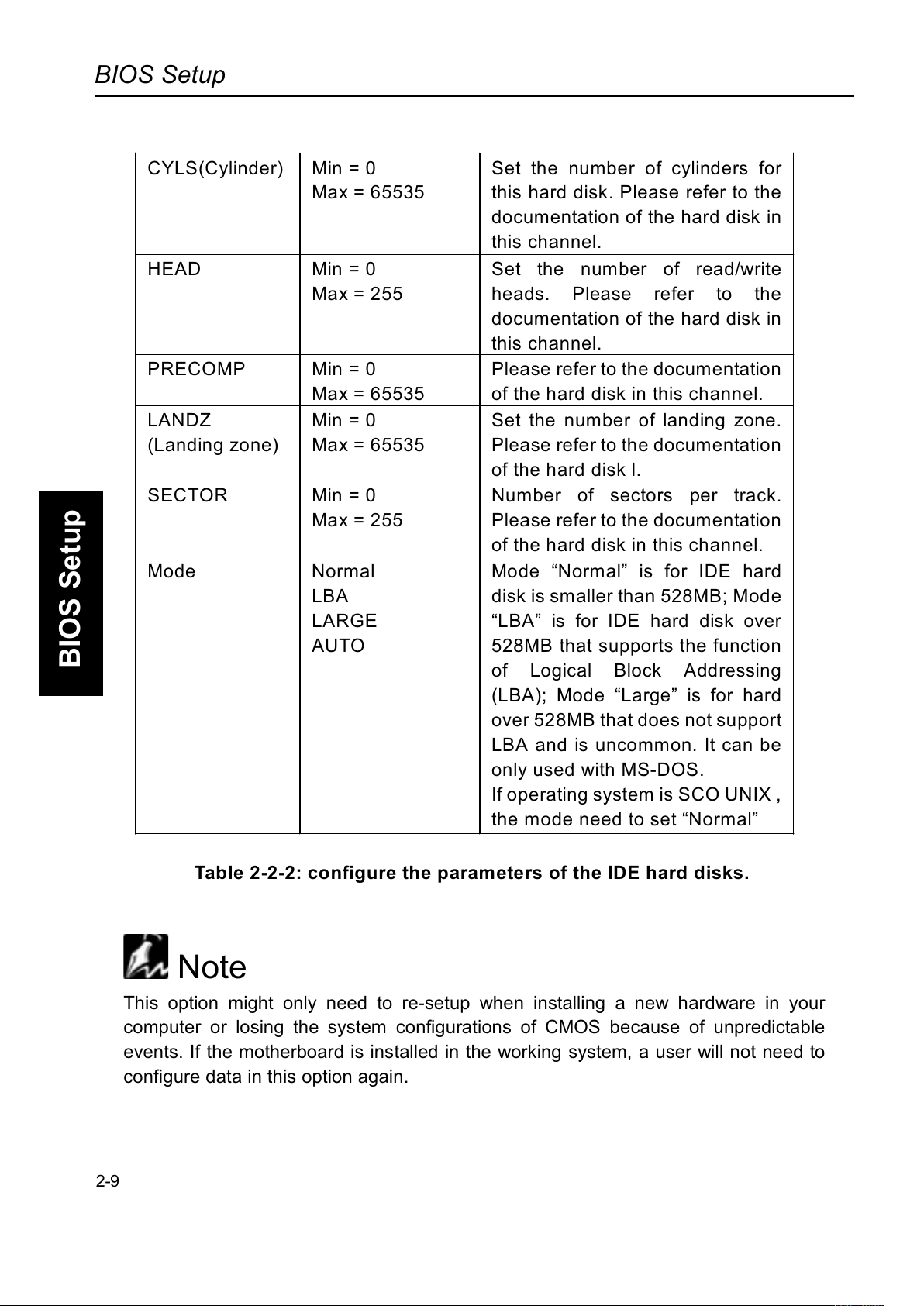
Table 2-2-2 shows how to configure the parameters of the IDE hard disks.
Item Options Description
Type None
Auto
User
If Selecting User, you need to fill
in all remaining fields, such as
Type, CYLS, PRECOMP, LANDZ
and MODE, on this selected item.
If the item AUTO is selected, only
item Mode can be set, the others
will remain 0. And when the
system boot up, system detect the
hard disk and configure it
automatically. None means no
device in the channel.
Size The capacity of the Hard Disk in
this channel. Please refer to the
documentation of the hard disk in
this channel.
2-8
Page 46
BIOS Setup
BIOS Setup
CYLS(Cylinder) Min = 0
Max = 65535
Set the number of cylinders for
this hard disk. Please refer to the
documentation of the hard disk in
this channel.
HEAD Min = 0
Max = 255
Set the number of read/write
heads. Please refer to the
documentation of the hard disk in
this channel.
PRECOMP Min = 0
Max = 65535
Please refer to the documentation
of the hard disk in this channel.
LANDZ
(Landing zone)
Min = 0
Max = 65535
Set the number of landing zone.
Please refer to the documentation
of the hard disk l.
SECTOR Min = 0
Max = 255
Number of sectors per track.
Please refer to the documentation
of the hard disk in this channel.
Mode Normal
LBA
LARGE
AUTO
Mode Normal is for IDE hard
disk is smaller than 528MB; Mode
LBA is for IDE hard disk over
528MB that supports the function
of Logical Block Addressing
(LBA); Mode Large is for hard
over 528MB that does not support
LBA and is uncommon. It can be
only used with MS-DOS.
If operating system is SCO UNIX ,
the mode need to set Normal
Table 2-2-2: configure the parameters of the IDE hard disks.
Note
This option might only need to re-setup when installing a new hardware in your
computer or losing the system configurations of CMOS because of unpredictable
events. If the motherboard is installed in the working system, a user will not need to
configure data in this option again.
2-9
Page 47
BIOS Setup
BIOS Setup
Section 3
Advanced Setup
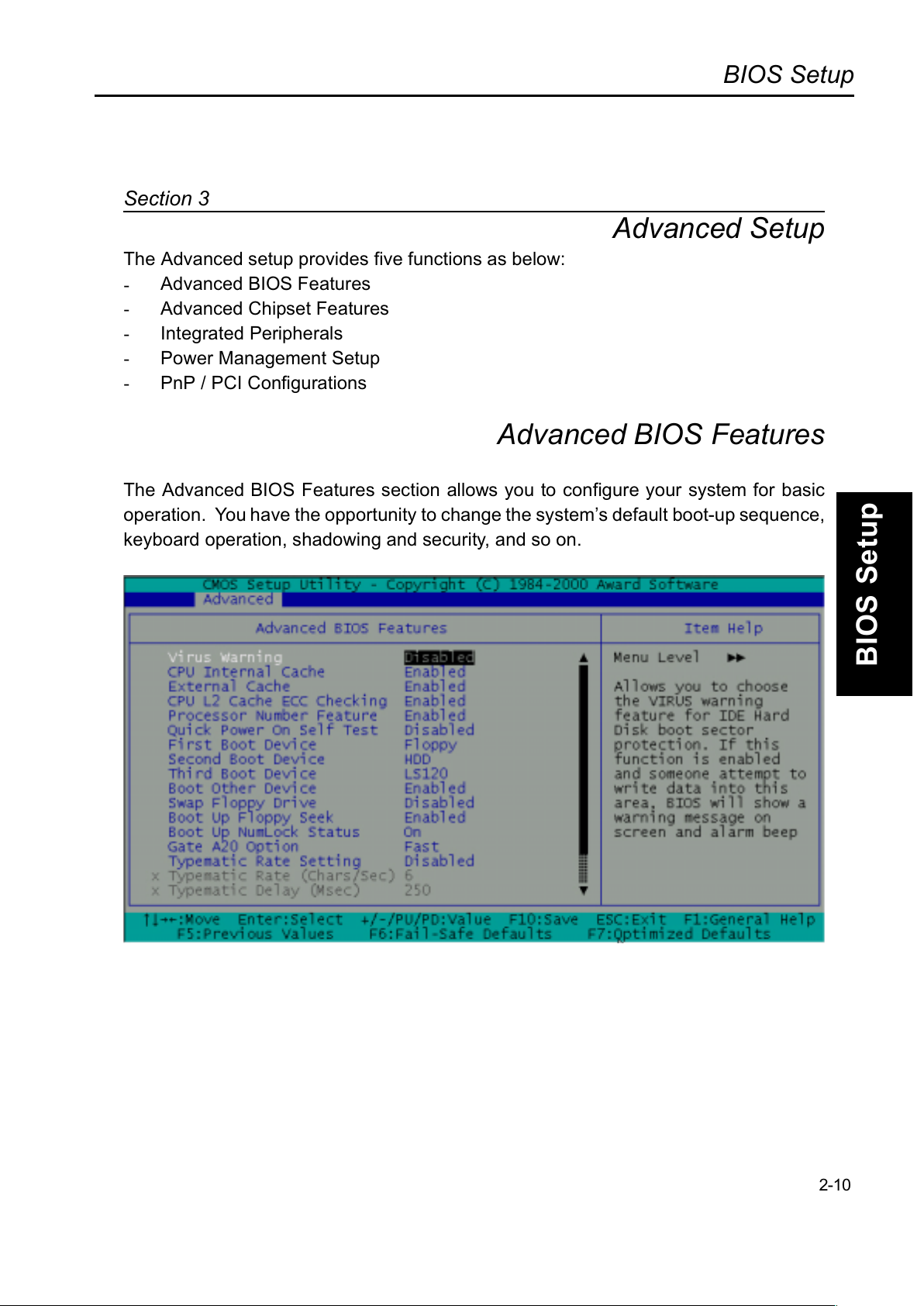
The Advanced setup provides five functions as below:
-
Advanced BIOS Features
-
Advanced Chipset Features
-
Integrated Peripherals
-
Power Management Setup
-
PnP / PCI Configurations
Advanced BIOS Features
The Advanced BIOS Features section allows you to configure your system for basic
operation. You have the opportunity to change the systems default boot-up sequence,
keyboard operation, shadowing and security, and so on.
2-10
Page 48
BIOS Setup
BIOS Setup
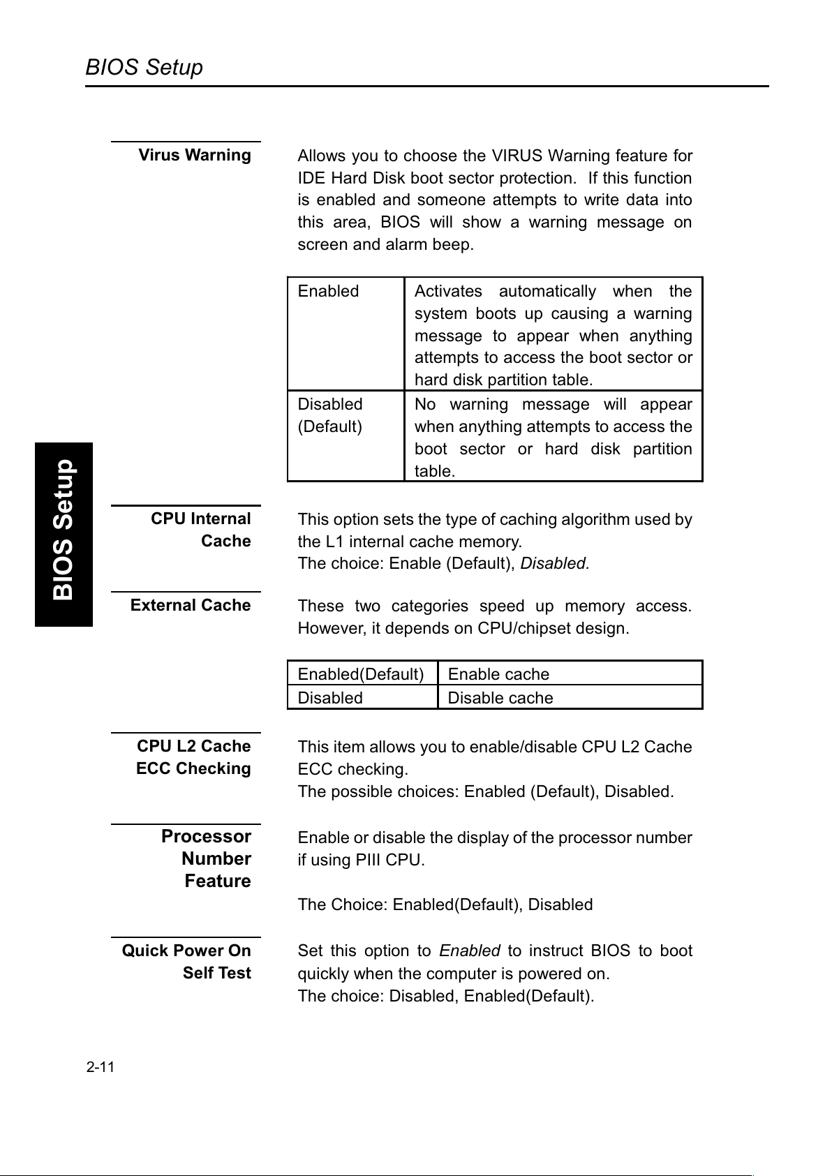
Virus Warning
Allows you to choose the VIRUS Warning feature for
IDE Hard Disk boot sector protection. If this function
is enabled and someone attempts to write data into
this area, BIOS will show a warning message on
screen and alarm beep.
Enabled
Activates automatically when the
system boots up causing a warning
message to appear when anything
attempts to access the boot sector or
hard disk partition table.
Disabled
(Default)
No warning message will appear
when anything attempts to access the
boot sector or hard disk partition
table.
CPU Internal
Cache
This option sets the type of caching algorithm used by
the L1 internal cache memory.
The choice: Enable (Default), Disabled.
External Cache
These two categories speed up memory access.
However, it depends on CPU/chipset design.
Enabled(Default) Enable cache
Disabled Disable cache
CPU L2 Cache
ECC Checking
This item allows you to enable/disable CPU L2 Cache
ECC checking.
The possible choices: Enabled (Default), Disabled.
Processor
Number
Feature
Enable or disable the display of the processor number
if using PIII CPU.
The Choice: Enabled(Default), Disabled
Quick Power On
Self Test
Set this option to Enabled to instruct BIOS to boot
quickly when the computer is powered on.
The choice: Disabled, Enabled(Default).
2-11
Page 49
BIOS Setup
BIOS Setup
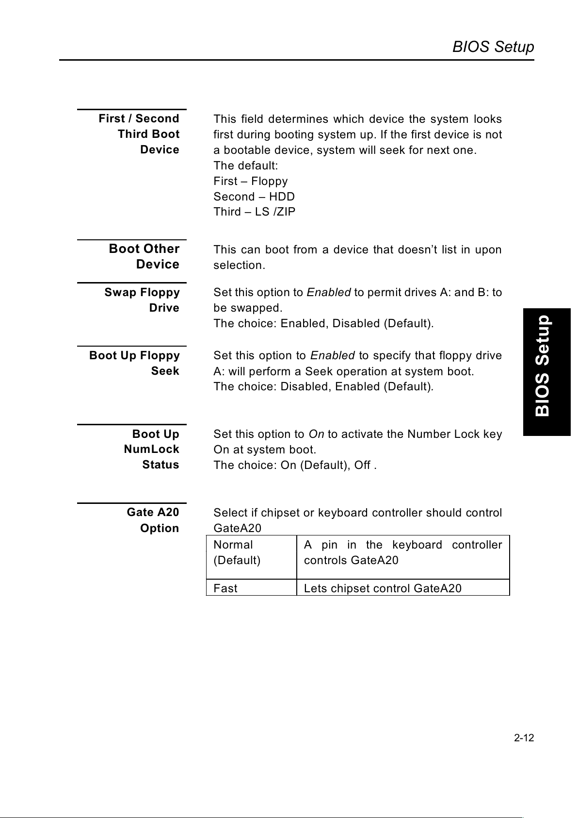
First / Second
Third Boot
Device
This field determines which device the system looks
first during booting system up. If the first device is not
a bootable device, system will seek for next one.
The default:
First Floppy
Second HDD
Third LS /ZIP
Boot Other
Device
This can boot from a device that doesnt list in upon
selection.
Swap Floppy
Drive
Set this option to Enabled to permit drives A: and B: to
be swapped.
The choice: Enabled, Disabled (Default).
Boot Up Floppy
Seek
Set this option to Enabled to specify that floppy drive
A: will perform a Seek operation at system boot.
The choice: Disabled, Enabled (Default).
Boot Up
NumLock
Status
Set this option to On to activate the Number Lock key
On at system boot.
The choice: On (Default), Off .
Select if chipset or keyboard controller should control
GateA20
Gate A20
Option
Normal
(Default)
A pin in the keyboard controller
controls GateA20
Fast Lets chipset control GateA20
2-12
Page 50
BIOS Setup
BIOS Setup
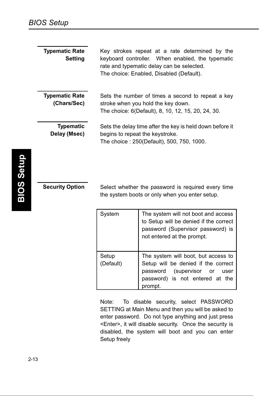
Typematic Rate
Setting
Key strokes repeat at a rate determined by the
keyboard controller. When enabled, the typematic
rate and typematic delay can be selected.
The choice: Enabled, Disabled (Default).
Typematic Rate
(Chars/Sec)
Sets the number of times a second to repeat a key
stroke when you hold the key down.
The choice: 6(Default), 8, 10, 12, 15, 20, 24, 30.
Type mat ic
Delay (Msec)
Sets the delay time after the key is held down before it
begins to repeat the keystroke.
The choice : 250(Default), 500, 750, 1000.
Security Option
Select whether the password is required every time
the system boots or only when you enter setup.
System The system will not boot and access
to Setup will be denied if the correct
password (Supervisor password) is
not entered at the prompt.
Setup
(Default)
The system will boot, but access to
Setup will be denied if the correct
password (supervisor or user
password) is not entered at the
prompt.
Note: To disable security, select PASSWORD
SETTING at Main Menu and then you will be asked to
enter password. Do not type anything and just press
<Enter>, it will disable security. Once the security is
disabled, the system will boot and you can enter
Setup freely
2-13
Page 51
BIOS Setup
BIOS Setup
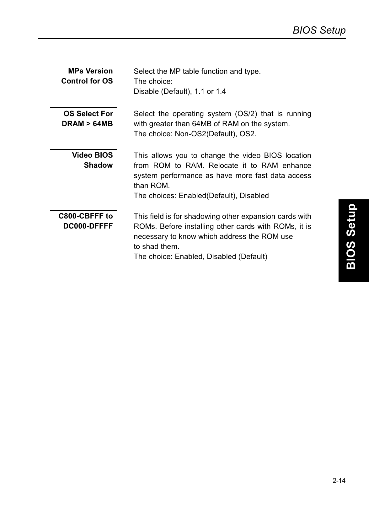
MPs Version
Control for OS
Select the MP table function and type.
The choice:
Disable (Default), 1.1 or 1.4
OS Select For
DRAM > 64MB
Select the operating system (OS/2) that is running
with greater than 64MB of RAM on the system.
The choice: Non-OS2(Default), OS2.
Video BIOS
Shadow
This allows you to change the video BIOS location
from ROM to RAM. Relocate it to RAM enhance
system performance as have more fast data access
than ROM.
The choices: Enabled(Default), Disabled
C800-CBFFF to
DC000-DFFFF
This field is for shadowing other expansion cards with
ROMs. Before installing other cards with ROMs, it is
necessary to know which address the ROM use
to shad them.
The choice: Enabled, Disabled (Default)
2-14
Page 52
BIOS Setup
BIOS Setup
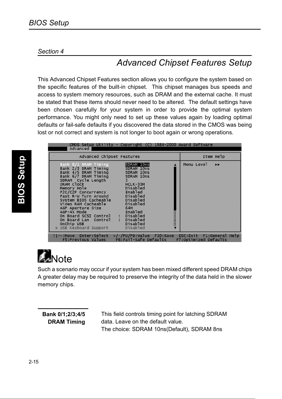
Advanced Chipset Features Setup
This Advanced Chipset Features section allows you to configure the system based on
the specific features of the built-in chipset. This chipset manages bus speeds and
access to system memory resources, such as DRAM and the external cache. It mus
t
be stated that these items should never need to be altered. The default settings have
been chosen carefully for your system in order to provide the optimal system
performance. You might only need to set up these values again by loading optimal
defaults or fail-safe defaults if you discovered the data stored in the CMOS was being
lost or not correct and system is not longer to boot again or wrong operations.
Note
Such a scenario may occur if your system has been mixed different speed DRAM chips
A
greater delay may be required to preserve the integrity of the data held in the slower
memory chips.
2-15
Section 4
This field controls timing point for latching SDRAM
Bank 0/1;2/3;4/5
DRAM Timing
data. Leave on the default value.
The choice: SDRAM 10ns(Default), SDRAM 8ns
Page 53
BIOS Setup
BIOS Setup
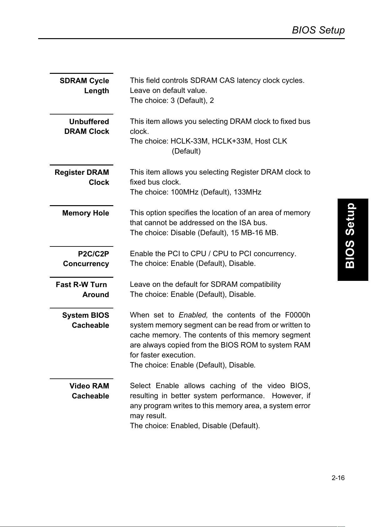
SDRAM Cycle
Length
This field controls SDRAM CAS latency clock cycles.
Leave on default value.
The choice: 3 (Default), 2
Unbuffered
DRAM Clock
This item allows you selecting DRAM clock to fixed bus
clock.
The choice: HCLK-33M, HCLK+33M, Host CLK
(Default)
Register DRAM
Clock
This item allows you selecting Register DRAM clock to
fixed bus clock.
The choice: 100MHz (Default), 133MHz
Memory Hole
This option specifies the location of an area of memory
that cannot be addressed on the ISA bus.
The choice: Disable (Default), 15 MB-16 MB.
P2C/C2P
Concurrency
Enable the PCI to CPU / CPU to PCI concurrency.
The choice: Enable (Default), Disable.
Fast R-W Turn
Around
Leave on the default for SDRAM compatibility
The choice: Enable (Default), Disable.
System BIOS
Cacheable
When set to Enabled, the contents of the F0000h
system memory segment can be read from or written to
cache memory. The contents of this memory segment
are always copied from the BIOS ROM to system RAM
for faster execution.
The choice: Enable (Default), Disable.
Video RAM
Cacheable
Select Enable allows caching of the video BIOS,
resulting in better system performance. However, if
any program writes to this memory area, a system error
may result.
The choice: Enabled, Disable (Default).
2-16
Page 54
BIOS Setup
BIOS Setup
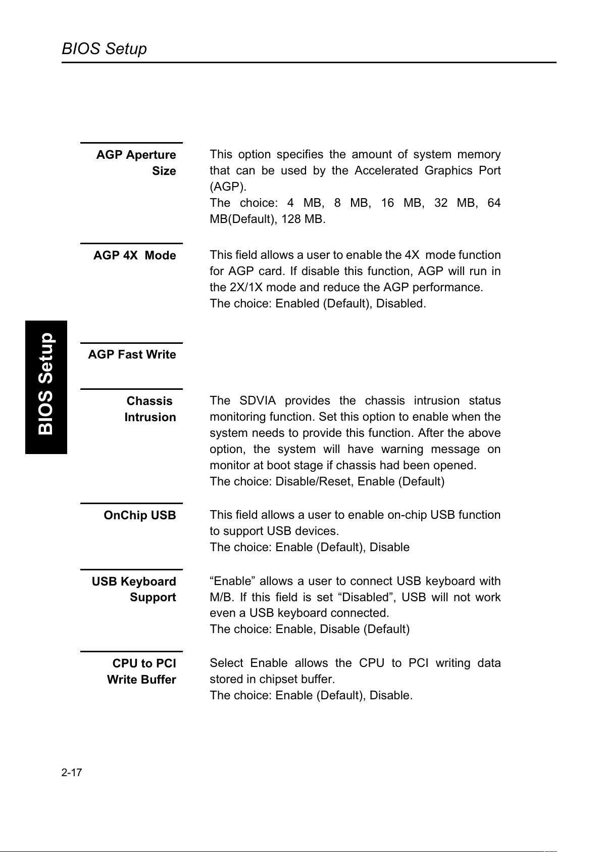
AGP Aperture
Size
This option specifies the amount of system memory
that can be used by the Accelerated Graphics Port
(AGP).
The choice: 4 MB, 8 MB, 16 MB, 32 MB, 64
MB(Default), 128 MB.
AGP 4X Mode
This field allows a user to enable the 4X mode function
for AGP card. If disable this function, AGP will run in
the 2X/1X mode and reduce the AGP performance.
The choice: Enabled (Default), Disabled.
AGP Fast Write
Chassis
Intrusion
The SDVIA provides the chassis intrusion status
monitoring function. Set this option to enable when the
system needs to provide this function. After the above
option, the system will have warning message on
monitor at boot stage if chassis had been opened.
The choice: Disable/Reset, Enable (Default)
OnChip USB
This field allows a user to enable on-chip USB function
to support USB devices.
The choice: Enable (Default), Disable
USB Keyboard
Support
Enable allows a user to connect USB keyboard with
M/B. If this field is set Disabled, USB will not work
even a USB keyboard connected.
The choice: Enable, Disable (Default)
CPU to PCI
Write Buffer
Select Enable allows the CPU to PCI writing data
stored in chipset buffer.
The choice: Enable (Default), Disable.
2-17
Page 55
BIOS Setup
BIOS Setup
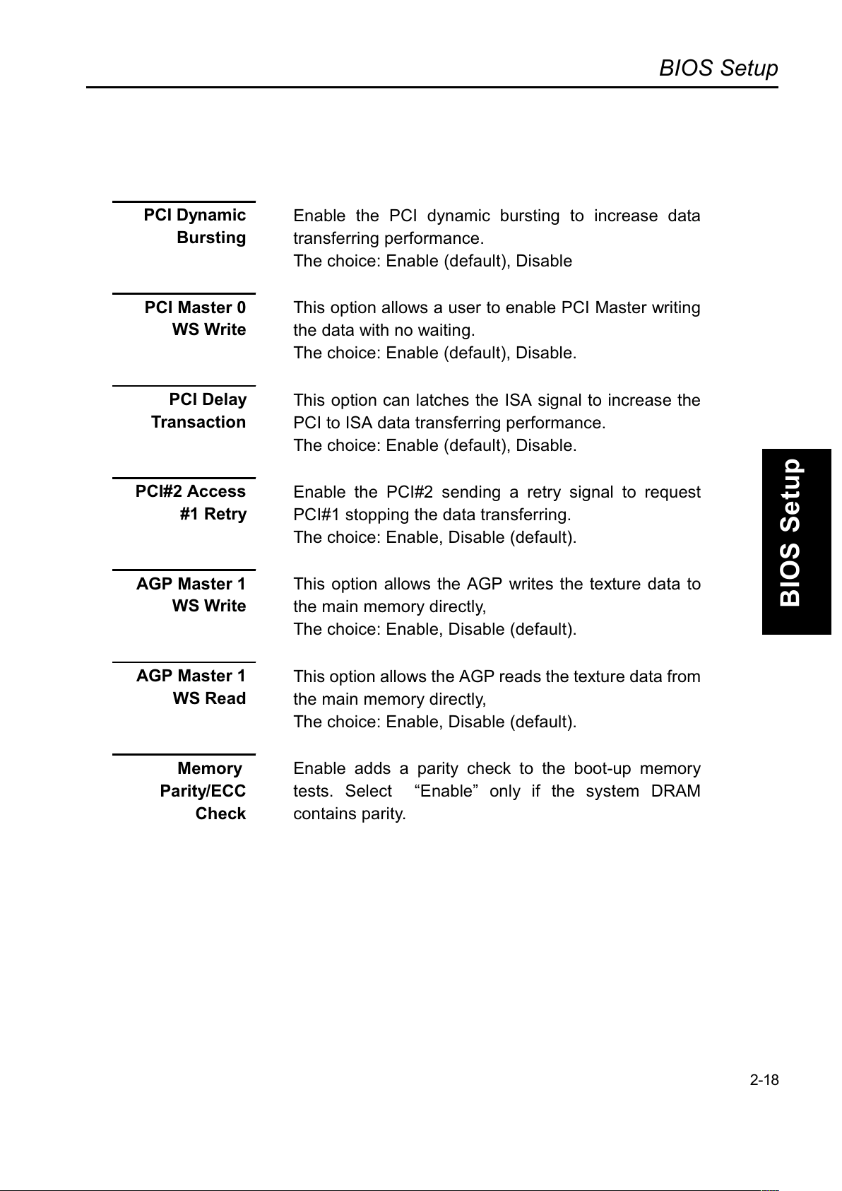
PCI Dynamic
Bursting
Enable the PCI dynamic bursting to increase data
transferring performance.
The choice: Enable (default), Disable
PCI Master 0
WS Write
This option allows a user to enable PCI Master writing
the data with no waiting.
The choice: Enable (default), Disable.
PCI Delay
Transaction
This option can latches the ISA signal to increase the
PCI to ISA data transferring performance.
The choice: Enable (default), Disable.
PCI#2 Access
#1 Retry
Enable the PCI#2 sending a retry signal to request
PCI#1 stopping the data transferring.
The choice: Enable, Disable (default).
AGP Master 1
WS Write
This option allows the AGP writes the texture data to
the main memory directly,
The choice: Enable, Disable (default).
AGP Master 1
WS Read
This option allows the AGP reads the texture data from
the main memory directly,
The choice: Enable, Disable (default).
Memory
Parity/ECC
Check
Enable adds a parity check to the boot-up memory
tests. Select Enable only if the system DRAM
contains parity.
2-18
Page 56
BIOS Setup
BIOS Setup
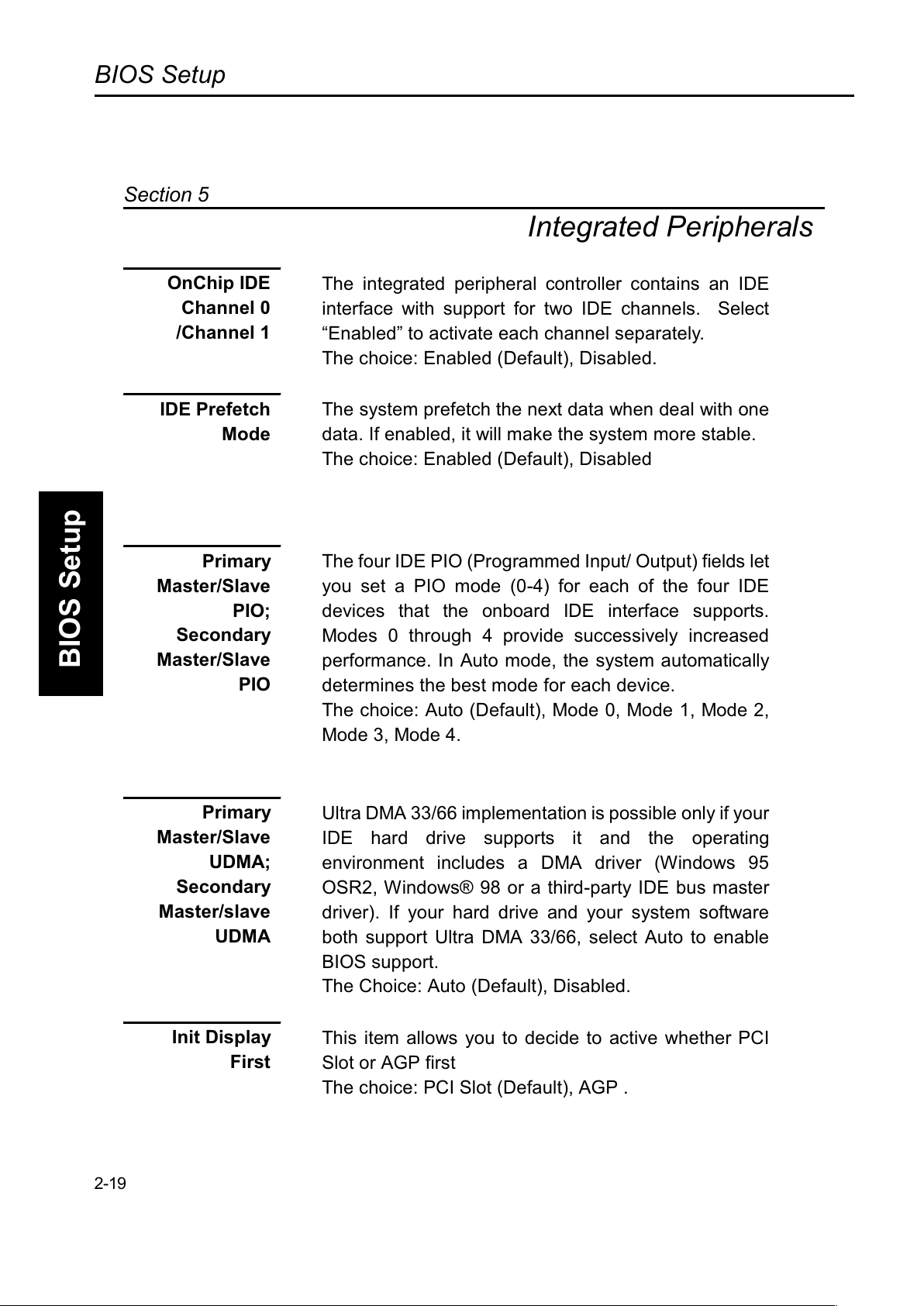
Integrated Peripherals
OnChip IDE
Channel 0
/Channel 1
The integrated peripheral controller contains an IDE
interface with support for two IDE channels. Select
Enabled to activate each channel separately.
The choice: Enabled (Default), Disabled.
IDE Prefetch
Mode
The system prefetch the next data when deal with one
data. If enabled, it will make the system more stable.
The choice: Enabled (Default), Disabled
Primary
Master/Slave
PIO;
Secondary
Master/Slave
PIO
The four IDE PIO (Programmed Input/ Output) fields let
you set a PIO mode (0-4) for each of the four IDE
devices that the onboard IDE interface supports.
Modes 0 through 4 provide successively increased
performance. In Auto mode, the system automatically
determines the best mode for each device.
The choice: Auto (Default), Mode 0, Mode 1, Mode 2,
Mode 3, Mode 4.
Primary
Master/Slave
UDMA;
Secondary
Master/slave
UDMA
Ultra DMA 33/66 implementation is possible only if your
IDE hard drive supports it and the operating
environment includes a DMA driver (Windows 95
OSR2, Windows® 98 or a third-party IDE bus master
driver). If your hard drive and your system software
both support Ultra DMA 33/66, select Auto to enable
BIOS support.
The Choice: Auto (Default), Disabled.
Init Display
First
This item allows you to decide to active whether PCI
Slot or AGP first
The choice: PCI Slot (Default), AGP .
2-19
Section 5
Page 57
BIOS Setup
BIOS Setup
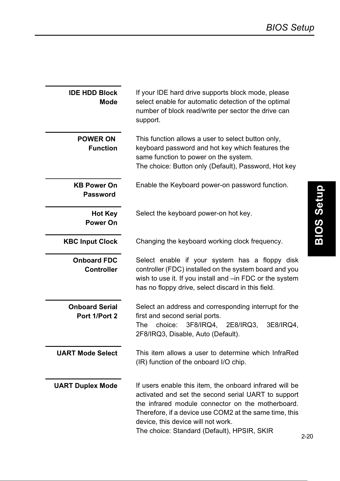
IDE HDD Block
Mode
If your IDE hard drive supports block mode, please
select enable for automatic detection of the optimal
number of block read/write per sector the drive can
support.
POWER ON
Function
This function allows a user to select button only,
keyboard password and hot key which features the
same function to power on the system.
The choice: Button only (Default), Password, Hot key
KB Power On
Password
Enable the Keyboard power-on password function.
Hot Key
Power On
Select the keyboard power-on hot key.
KBC Input Clock
Changing the keyboard working clock frequency.
Onboard FDC
Controller
Select enable if your system has a floppy disk
controller (FDC) installed on the system board and you
wish to use it. If you install and in FDC or the system
has no floppy drive, select discard in this field.
Onboard Serial
Port 1/Port 2
Select an address and corresponding interrupt for the
first and second serial ports.
The choice: 3F8/IRQ4, 2E8/IRQ3, 3E8/IRQ4,
2F8/IRQ3, Disable, Auto (Default).
UART Mode Select
This item allows a user to determine which InfraRed
(IR) function of the onboard I/O chip.
UART Duplex Mode
If users enable this item, the onboard infrared will be
activated and set the second serial UART to support
the infrared module connector on the motherboard.
Therefore, if a device use COM2 at the same time, this
device, this device will not work.
The choice: Standard (Default), HPSIR, SKIR
2-20
Page 58
BIOS Setup
BIOS Setup
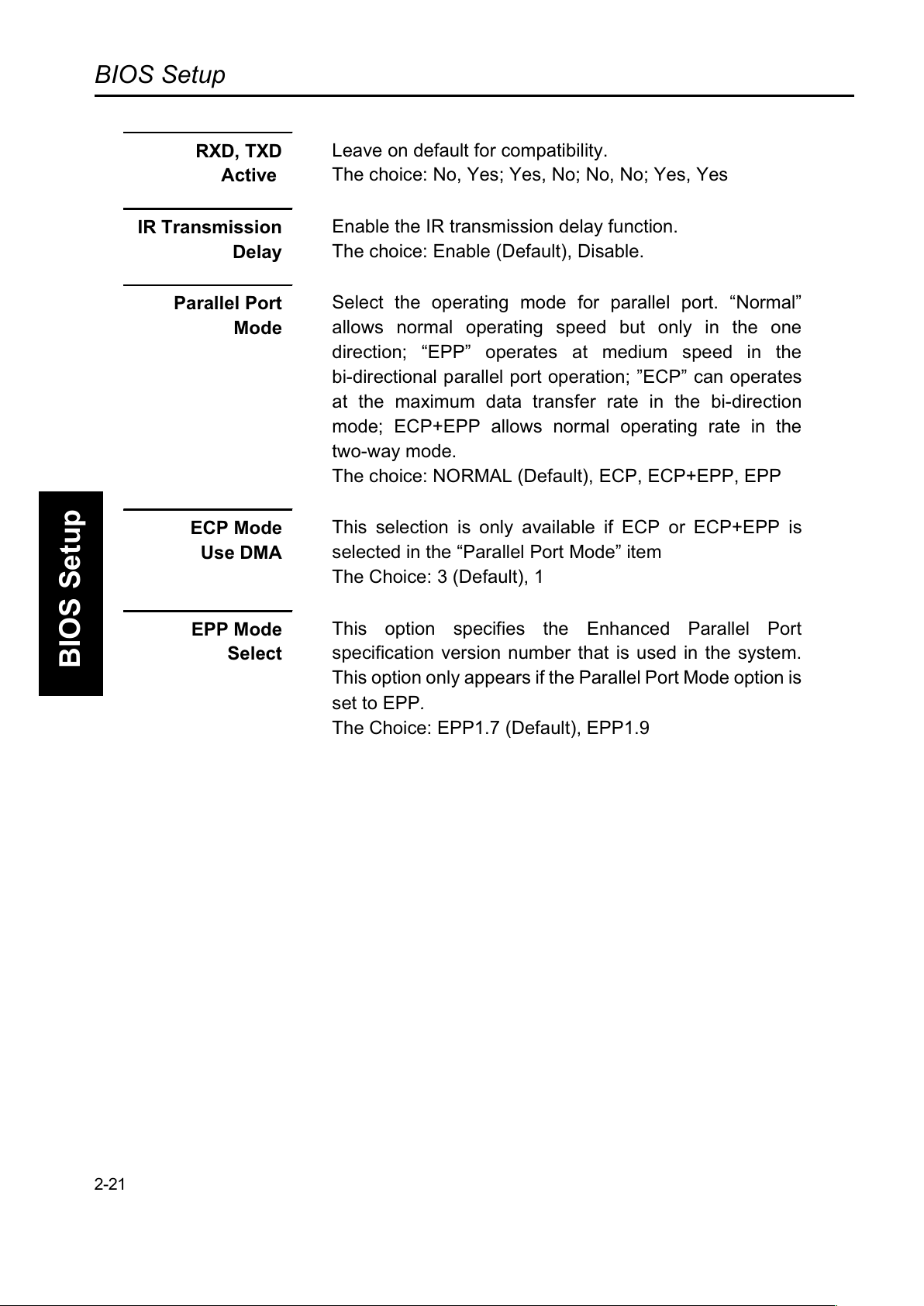
RXD, TXD
Active
Leave on default for compatibility.
The choice: No, Yes; Yes, No; No, No; Yes, Yes
IR Transmission
Delay
Enable the IR transmission delay function.
The choice: Enable (Default), Disable.
Parallel Port
Mode
Select the operating mode for parallel port. Normal
allows normal operating speed but only in the one
direction; EPP operates at medium speed in the
bi-directional parallel port operation; ECP can operates
at the maximum data transfer rate in the bi-direction
mode; ECP+EPP allows normal operating rate in the
two-way mode.
The choice: NORMAL (Default), ECP, ECP+EPP, EPP
ECP Mode
Use DMA
This selection is only available if ECP or ECP+EPP is
selected in the Parallel Port Mode item
The Choice: 3 (Default), 1
EPP Mode
Select
This option specifies the Enhanced Parallel Port
specification version number that is used in the system.
This option only appears if the Parallel Port Mode option is
set to EPP.
The Choice: EPP1.7 (Default), EPP1.9
2-21
Page 59
BIOS Setup
BIOS Setup
2-22
(This Page Intentionally Left Blank for Notes)
Page 60
BIOS Setup
BIOS Setup
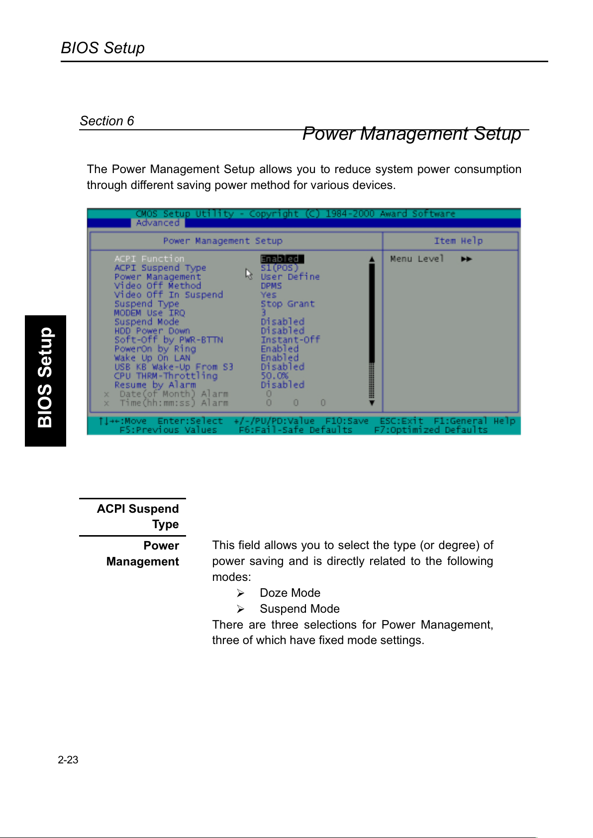
Power Management Setup
The Power Management Setup allows you to reduce system power consumption
through different saving power method for various devices.
ACPI Suspend
Type
Power
Management
This field allows you to select the type (or degree) of
power saving and is directly related to the following
modes:
#
Doze Mode
#
Suspend Mode
There are three selections for Power Management,
three of which have fixed mode settings.
2-23
Section 6
Page 61
BIOS Setup
BIOS Setup
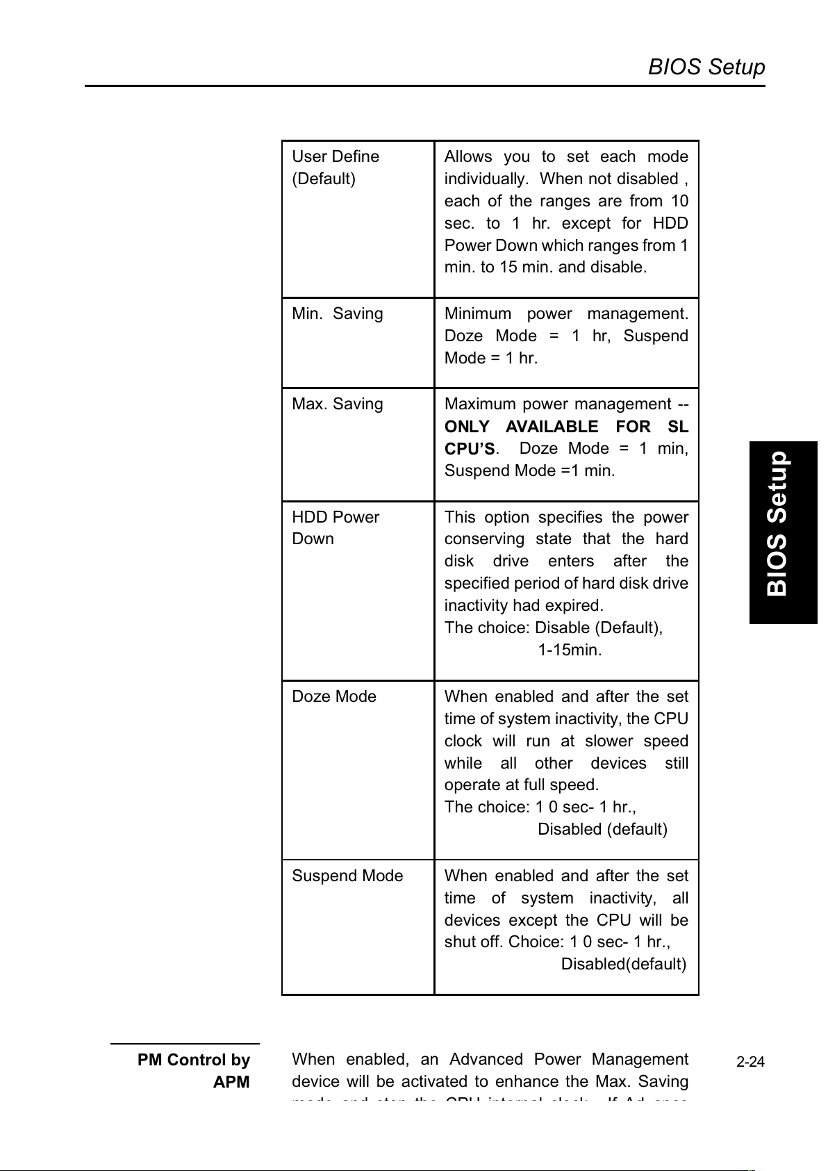
User Define
(Default)
Allows you to set each mode
individually. When not disabled ,
each of the ranges are from 10
sec. to 1 hr. except for HDD
Power Down which ranges from 1
min. to 15 min. and disable.
Min. Saving Minimum power management.
Doze Mode = 1 hr, Suspend
Mode = 1 hr.
Max. Saving Maximum power management --
ONLY AVAILABLE FOR SL
CPUS
. Doze Mode = 1 min,
Suspend Mode =1 min.
HDD Power
Down
This option specifies the power
conserving state that the hard
disk drive enters after the
specified period of hard disk drive
inactivity had expired.
The choice: Disable (Default),
1-15min.
Doze Mode When enabled and after the set
time of system inactivity, the CPU
clock will run at slower speed
while all other devices still
operate at full speed.
The choice: 1 0 sec- 1 hr.,
Disabled (default)
Suspend Mode When enabled and after the set
time of system inactivity, all
devices except the CPU will be
shut off. Choice: 1 0 sec- 1 hr.,
Disabled(default)
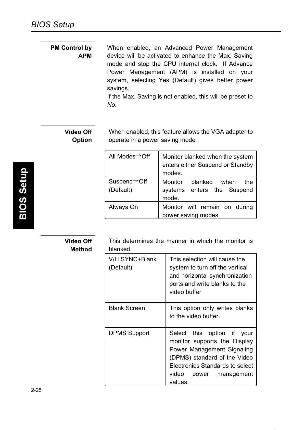
PM Control by
APM
When enabled, an Advanced Power Management
device will be activated to enhance the Max. Saving
2-24
Page 62
BIOS Setup
BIOS Setup
Video Off
Option
When enabled, this feature allows the VGA adapter to
operate in a power saving mode
All Modes÷Off
Monitor blanked when the system
enters either Suspend or Standby
modes.
Suspend÷Off
(Default)
Monitor blanked when the
systems enters the Suspend
mode.
Always On Monitor will remain on during
power saving modes.
Video Off
Method
This determines the manner in which the monitor is
blanked.
V/H SYNC+Blank
(Default)
This selection will cause the
system to turn off the vertical
and horizontal synchronization
ports and write blanks to the
video buffer
Blank Screen This option only writes blanks
to the video buffer.
DPMS Support Select this option if your
monitor supports the Display
Power Management Signaling
(DPMS) standard of the Video
Electronics Standards to select
video power management
values.
2-25
PM Control by
APM
When enabled, an Advanced Power Management
device will be activated to enhance the Max. Saving
mode and stop the CPU internal clock. If Advance
Power Management (APM) is installed on your
system, selecting Yes (Default) gives better power
savings.
If the Max. Saving is not enabled, this will be preset to
No.
Page 63
BIOS Setup
BIOS Setup
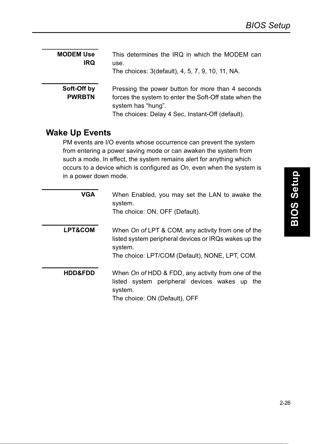
MODEM Use
IRQ
This determines the IRQ in which the MODEM can
use.
The choices: 3(default), 4, 5, 7, 9, 10, 11, NA.
Soft-Off by
PWRBTN
Pressing the power button for more than 4 seconds
forces the system to enter the Soft-Off state when the
system has hung.
The choices: Delay 4 Sec, Instant-Off (default).
Wake Up Events
PM events are I/O events whose occurrence can prevent the system
from entering a power saving mode or can awaken the system from
such a mode. In effect, the system remains alert for anything which
occurs to a device which is configured as On, even when the system is
in a power down mode.
VGA
When Enabled, you may set the LAN to awake the
system.
The choice: ON, OFF (Default).
LPT&COM
When On of LPT & COM, any activity from one of the
listed system peripheral devices or IRQs wakes up the
system.
The choice: LPT/COM (Default), NONE, LPT, COM.
HDD&FDD
When On of HDD & FDD, any activity from one of the
listed system peripheral devices wakes up the
system.
The choice: ON (Default), OFF
2-26
Page 64
BIOS Setup
BIOS Setup
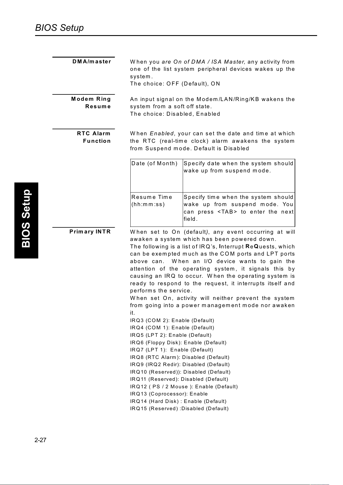
DMA/master
W hen you are On of DMA / ISA Master, any activity from
one of the list system peripheral devices wakes up the
system .
The choice: OFF (Default), ON
Modem Ring
Resume
An input signal on the Modem/LAN/Ring/KB wakens the
system from a soft off state.
The choice: Disabled, Enabled
RTC Alarm
Function
When Enabled, your can set the date and tim e at which
the RTC (real-time clock) alarm awakens the system
from Suspend mode. Default is Disabled
Date (of Month) Specify date when the system should
wak e u p fro m susp e nd m ode.
Resume Time
(hh:m m :ss)
Specify time when the system should
wake up from suspend mode. You
can press <TAB> to enter the next
field .
Prim ary IN TR
W hen set to On (default), any event occurring at will
awaken a system which has been powered down.
Th e following is a list of IRQ s , Interrupt ReQuests, which
can be exempted m uch as the COM ports and LPT ports
above can. When an I/O device wants to gain the
attention of the operating system , it signals this by
causing an IRQ to occur. W hen the operating system is
ready to respond to the request, it interrupts itself and
performs the service.
W hen set On, activity will neither prevent the system
from going into a power management mode nor awaken
it.
IRQ3 (C O M 2): Enable (Defa ult)
IRQ4 (C O M 1): Enable (D efault)
IRQ 5 (LP T 2): Enable (Default)
IRQ6 (Floppy Disk): Enable (Default)
IRQ7 (LPT 1 ): E nable (D efault)
IRQ8 (RTC Alarm): Disabled (Default)
IRQ9 (IR Q 2 Redir): Disabled (D efault)
IRQ10 (Reserved)): Disabled (Default)
IRQ11 (Reserved): Disabled (Default)
IRQ12 ( PS / 2 M ous e ): Enable (Default)
IRQ13 (Coprocessor): Enable
IRQ14 (Hard Disk) : Enable (Default)
IRQ15 (Reserved) :Disabled (Default)
2-27
Page 65
BIOS Setup
BIOS Setup
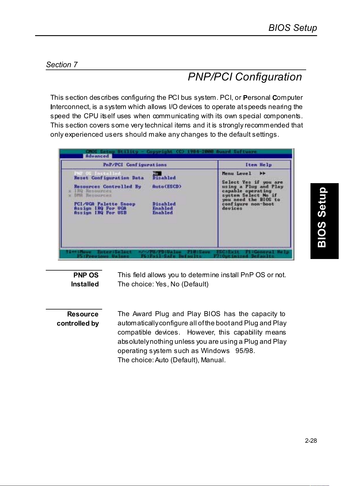
PNP/PCI Configuration
This section des cribes configuring the PCI bus system. PCI, or Personal Computer
I
nterconnect, is a system which allows I/O devices to operate at speeds nearing the
speed the CPU itself uses when communicating with its own special components.
This section covers some very technical items and it is strongly recommended that
only experienced users should make any changes to the default settings.
PNP OS
Installed
This field allows you to determine install PnP OS or not.
The choice: Yes, No (Default)
Resour ce
controlled by
The Award Plug and Play BIOS has the capacity to
automatically configure all of the boot and Plug and Play
compatible devices. However, this capability means
absolutely nothing unless you are using a Plug and Play
operating s ystem s uch as Windows95/98.
The choice: Auto (Default), Manual.
2-28
Section 7
Page 66
BIOS Setup
BIOS Setup
Reset
Configuration
Data
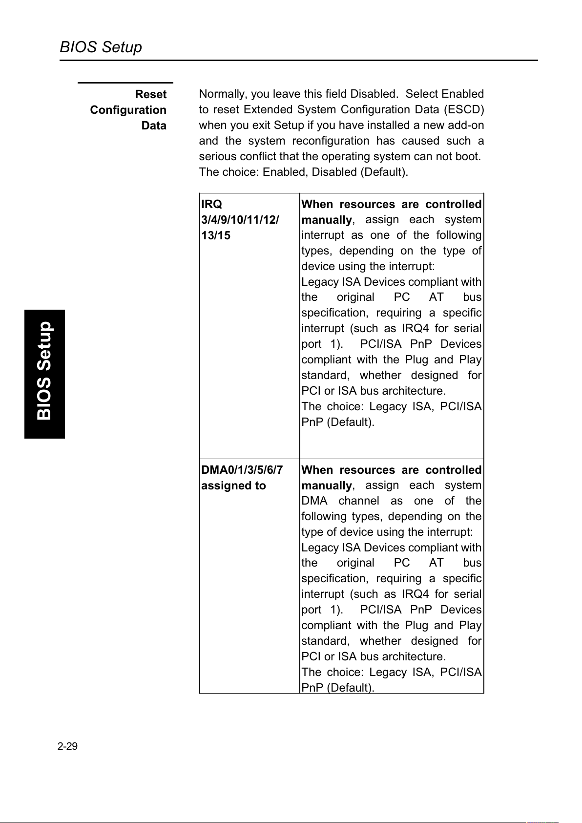
Normally, you leave this field Disabled. Select Enabled
to reset Extended System Configuration Data (ESCD)
when you exit Setup if you have installed a new add-on
and the system reconfiguration has caused such a
serious conflict that the operating system can not boot.
The choice: Enabled, Disabled (Default).
IRQ
3/4/9/10/11/12/
13/15
When resources are controlled
manually
, assign each system
interrupt as one of the following
types, depending on the type of
device using the interrupt:
Legacy ISA Devices compliant with
the original PC AT bus
specification, requiring a specific
interrupt (such as IRQ4 for serial
port 1). PCI/ISA PnP Devices
compliant with the Plug and Play
standard, whether designed for
PCI or ISA bus architecture.
The choice: Legacy ISA, PCI/ISA
PnP (Default).
DMA0/1/3/5/6/7
assigned to
When resources are controlled
manually
, assign each system
DMA channel as one of the
following types, depending on the
type of device using the interrupt:
Legacy ISA Devices compliant with
the original PC AT bus
specification, requiring a specific
interrupt (such as IRQ4 for serial
port 1). PCI/ISA PnP Devices
compliant with the Plug and Play
standard, whether designed for
PCI or ISA bus architecture.
The choice: Legacy ISA, PCI/ISA
PnP (Default).
2-29
Page 67
BIOS Setup
BIOS Setup
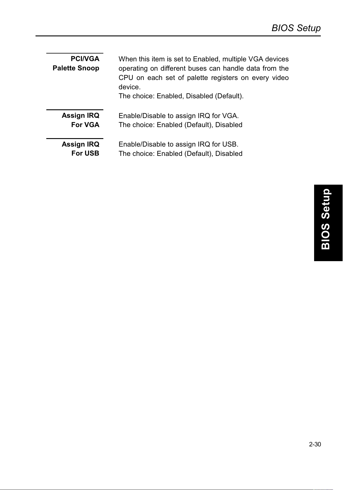
PCI/VGA
Palette Snoop
When this item is set to Enabled, multiple VGA devices
operating on different buses can handle data from the
CPU on each set of palette registers on every video
device.
The choice: Enabled, Disabled (Default).
Assign IRQ
For VGA
Enable/Disable to assign IRQ for VGA.
The choice: Enabled (Default), Disabled
Assign IRQ
For USB
Enable/Disable to assign IRQ for USB.
The choice: Enabled (Default), Disabled
2-30
Page 68
BIOS Setup
BIOS Setup
Section 8
Load Fail Safe /Optimal Settings
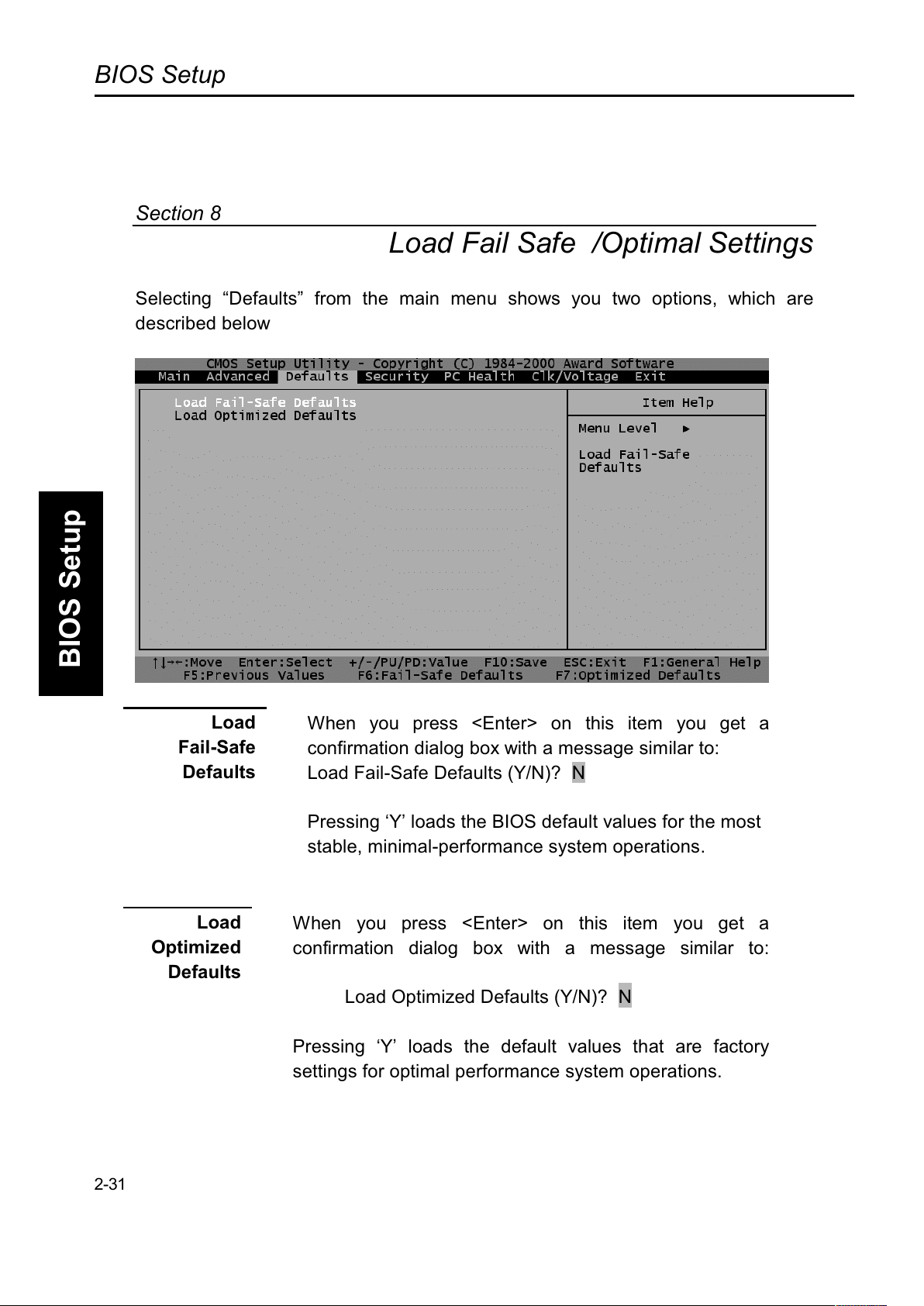
Selecting Defaults from the main menu shows you two options, which are
described below
Load
Fail-Safe
Defaults
When you press <Enter> on this item you get a
confirmation dialog box with a message similar to:
Load Fail-Safe Defaults (Y/N)? N
Pressing Y loads the BIOS default values for the most
stable, minimal-performance system operations.
Load
Optimized
Defaults
When you press <Enter> on this item you get a
confirmation dialog box with a message similar to:
Load Optimized Defaults (Y/N)? N
Pressing Y loads the default values that are factory
settings for optimal performance system operations.
2-31
Page 69
BIOS Setup
BIOS Setup
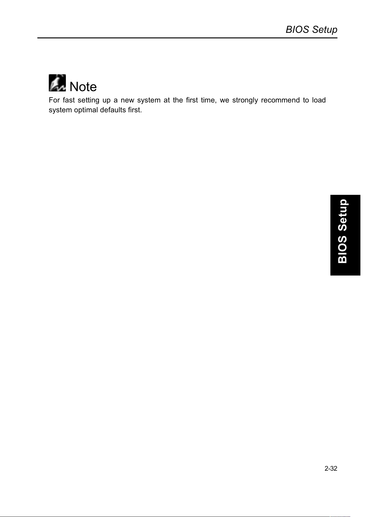
Note
For fast setting up a new system at the first time, we strongly recommend to load
system optimal defaults first.
2-32
Page 70
BIOS Setup
BIOS Setup
Section 9
Security
You may set either supervisor or user password, or both for different system
securities. The differences between are:
Set
SUPERVISSOR
PASSWORD
You may enter and change the options of the setup menus.
(Also refer Security Option In the BIOS Features Setup )
Set
USER
PASSWORD
You may only enter but do not have the right to change the
options of the setup menus. When you select this function, the
following message will appear at the center of the screen to
assist you in creating a password. (Also refer Security Option
In the BIOS Features Setup )
ENTER
PASSWORD
Type the password, up to eight characters in length, and press
<Enter>. The password typed now will clear any previously
entered password from CMOS memory. You will be asked to
confirm the password. Type the password again and press
<Enter>. You may also press <Esc> to abort the selection and
not enter a password.
PASSWORD
DISABLED
To disable a password, just press <Enter> when you are
prompted to enter the password. A message will confirm the
password will be disabled. Once the password is disabled, the
system will boot and you can enter Setup freely.
When a password has been enabled, you will be prompted to
enter it every time you try to enter Setup. This prevents an
unauthorized person from changing any part of your system
configuration.
Additionally, when a password is enabled, you may also
require the BIOS to request a password every time your
system is rebooted. This would prevent unauthorized use of
your computer.
You determine when the password is required within the BIOS
Features Setup Menu and its Security option (see Section 3).
If the Security option is set to System, the password will be
required both at boot and at entry to Setup. If set to Setup,
prompting only occurs when trying to enter Setup.
2-33
Page 71
BIOS Setup
BIOS Setup
Section 10
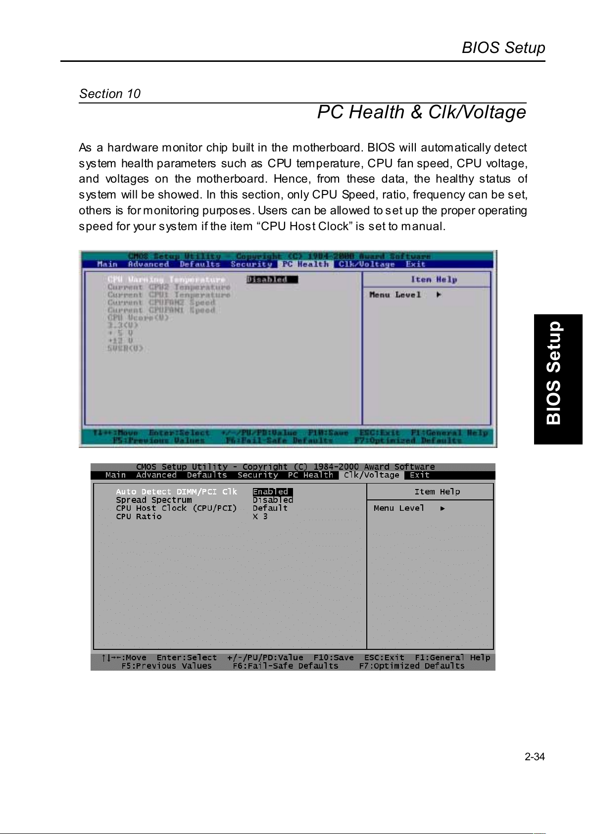
PC Health & Clk/Voltage
A
s a hardware monitor chip built in the motherboard. BIOS will automatically detect
system health parameters such as CPU temperature, CPU fan speed, CPU voltage
,
and voltages on the motherboard. Hence, from these data, the healthy status o
f
system will be showed. In this section, only CPU Speed, ratio, frequency can be set
,
others is for monitoring purposes. Users can be allowed to set up the proper operating
speed for your system if the item CPU Host Clock is set to m anual.
2-34
Page 72
BIOS Setup
BIOS Setup
PC Health
CPU Warning
Temperature
This item allows you to set the CPU warning temperature.
The choice: Disable (Default), 50ºC/122
ºF, 53ºC/ 127ºF,
56ºC/ 133ºF, 60ºC/ 140ºF, 63ºC/ 145ºF, 66ºC/ 151ºF,
70ºC/ 158ºF
Shutdown
Temperature
This item allows you to set the system shutdown
temperature.
The Choice: Disable (Default), 60
ºC/ 140ºF, 65ºC/ 149ºF,
70ºC/ 158ºF
Clk/Voltage
Auto Detect
DIMM/PCI Clk
This item allows you to enable/disable auto detect
DIMM/PCI clock.
The choice: Enable, Disable (Default)
Spread
Spectrum
This item allows you to enable/disable the spread
spectrum modulate.
The choice: Enable, Disable (Default)
CPU Host Clock
(CPU/PCI)
This item allows you to select the CPU speed.
The choice will depend on the FSB Frequency of CPU.
The choice: 66/33, 75/37, 83/41, 95/31, 100/33, 103/34,
112/37, 124/31, 129/32, 133/33, 138/34, 140/35, 150/37
CPU Ratio
This item allows you to select the CPU ratio. This
maximum setting value depends on the maximum CPU
operating frequency.
The choice: X 3 (Default), X 3.5, X 4,
X 4.5, X 5, X 5.5, X 6, X 6.5,X 7,X 7.5,X 8
2-35
Page 73
BIOS Setup
BIOS Setup
Section 11
Exit
Save & Exit
Setup
Pressing <Enter> on this item asks for confirmation:
Save to CMOS and EXIT (Y/N)? Y
Pressing Y to stores the all present setting values a user made in this time into
CMOS. Therefore next time you boot your computer up, the BIOS will re-configure
your system according data in CMOS.
Exit Without
Saving
Pressing <Enter> on this item asks for confirmation:
Quit without saving (Y/N)? Y
This allows you exiting Setup without changing previous setting values in CMOS.
The previous selections remain in effect. This will exit the Setup utility and restarts
your computer when click this selection.
2-36
Page 74
Flash ROM
Flash ROM
+D=FJAH!
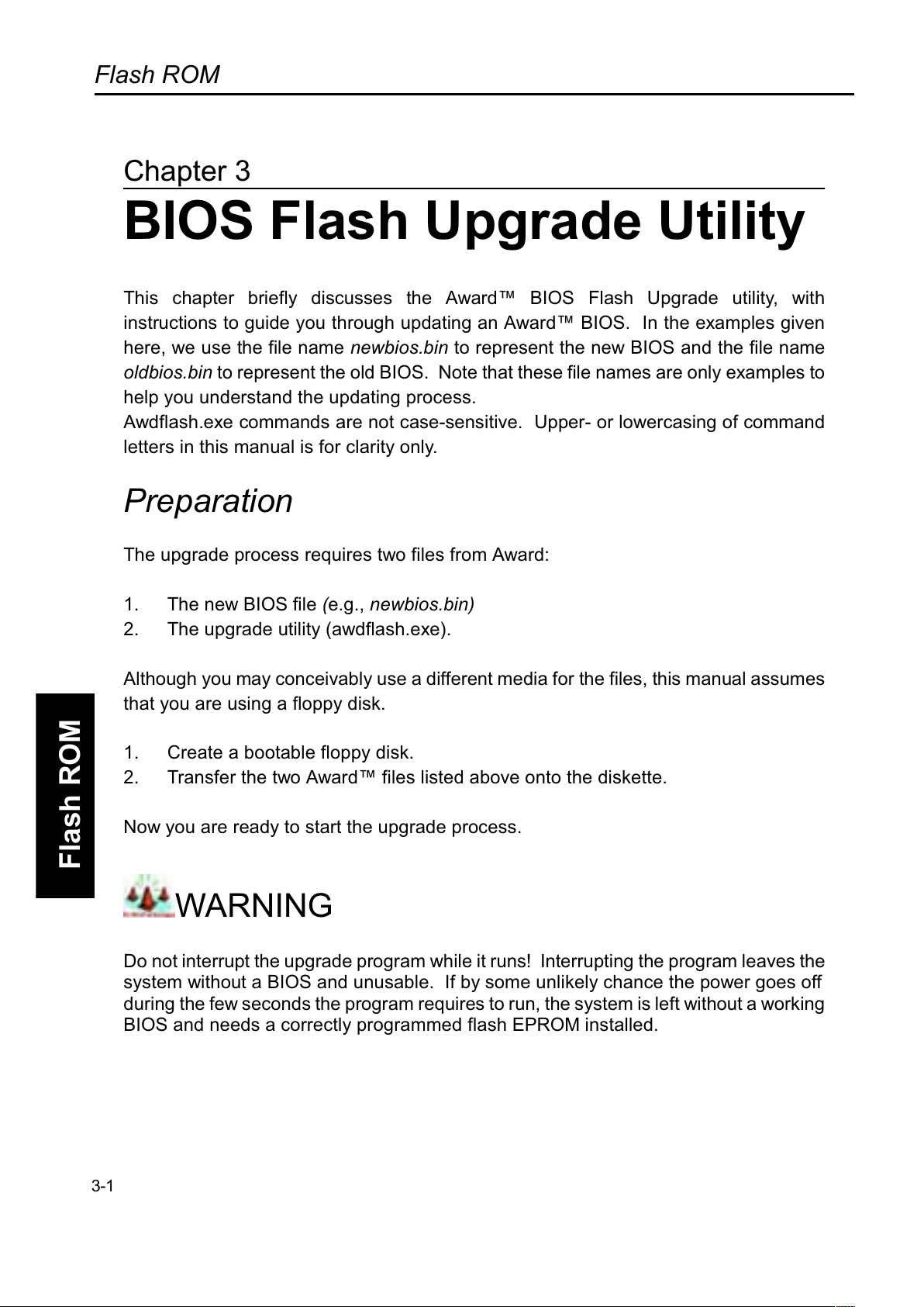
BIOS Flash Upgrade Utility
This chapter briefly discusses the Award BIOS Flash Upgrade utility, with
instructions to guide you through updating an Award BIOS. In the examples given
here, we use the file name newbios.bin to represent the new BIOS and the file name
oldbios.bin to represent the old BIOS. Note that these file names are only examples to
help you understand the updating process.
A
wdflash.exe commands are not case-sensitive. Upper- or lowercasing of command
letters in this manual is for clarity only.
Preparation
The upgrade process requires two files from Award:
1. The new BIOS file (e.g., newbios.bin)
2. The upgrade utility (awdflash.exe).
A
lthough you may conceivably use a different media for the files, this manual assumes
that you are using a floppy disk.
1. Create a bootable floppy disk.
2. Transfer the two Award files listed above onto the diskette.
Now you are ready to start the upgrade process.
WARNING
Do not interrupt the upgrade program while it runs! Interrupting the program leaves the
system without a BIOS and unusable. If by some unlikely chance the power goes off
during the few seconds the program requires to run, the system is left without a working
BIOS and needs a correctly programmed flash EPROM installed.
3-1
Page 75
Flash ROM
Flash ROM
Running the Program
1. Boot the system from the bootable floppy diskette you created. Booting from
the diskette bypasses loading drivers from the CONFIG.SYS and
AUTOEXEC.BAT files on the hard drive, eliminating the possibility of loading a
program (e.g., a memory manager) that conflicts with the Award flash utility.
NOTE:
The Award flash utility cannot run when EMM386 or QEMM are loaded. If you try,
an error message appears.
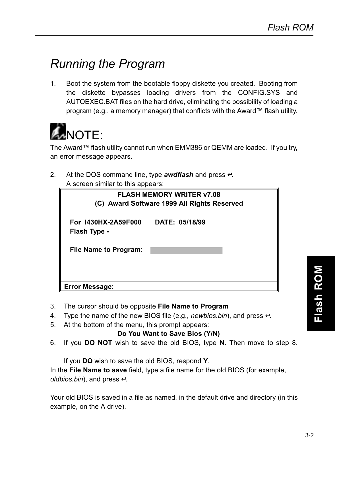
2. At the DOS command line, type awdflash and press ↵↵↵↵.
A screen similar to this appears:
FLASH MEMORY WRITER v7.08
(C) Award Software 1999 All Rights Reserved
For I430HX-2A59F000 DATE: 05/18/99
Flash Type -
File Name to Program:
Error Message:
3. The cursor should be opposite File Name to Program
4. Type the name of the new BIOS file (e.g.,
newbios.bin
), and press ↵.
5. At the bottom of the menu, this prompt appears:
Do You Want to Save Bios (Y/N)
6. If you DO NOT wish to save the old BIOS, type N. Then move to step 8.
If you DO wish to save the old BIOS, respond Y.
In the File Name to save field, type a file name for the old BIOS (for example,
oldbios.bin
), and press ↵.
Your old BIOS is saved in a file as named, in the default drive and directory (in this
example, on the A drive).
3-2
Page 76
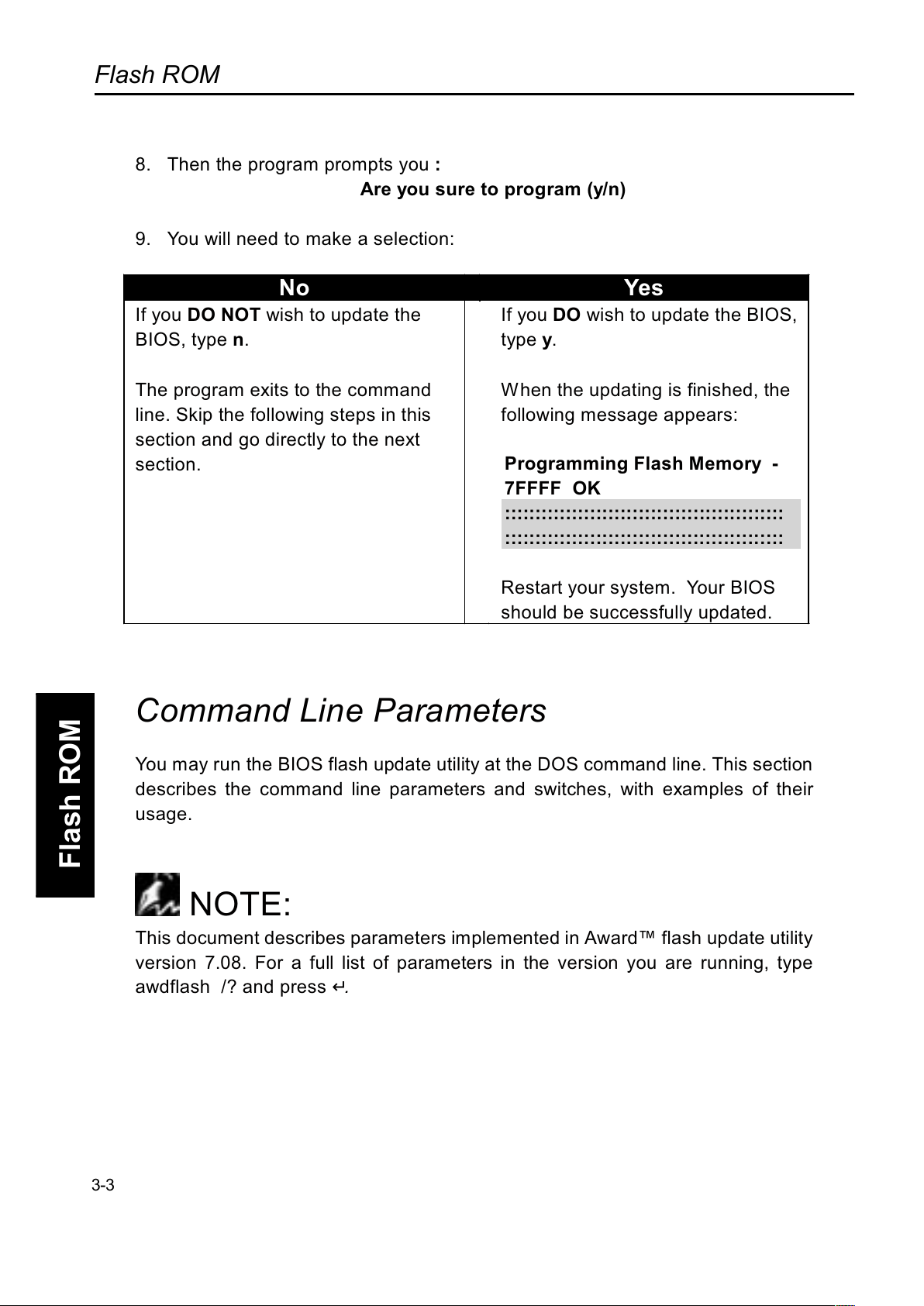
Flash ROM
Flash ROM
8. Then the program prompts you :
Are you sure to program (y/n)
9. You will need to make a selection:
No Yes
If you DO NOT wish to update the
BIOS, type n.
The program exits to the command
line. Skip the following steps in this
section and go directly to the next
section.
If you DO wish to update the BIOS,
type y.
When the updating is finished, the
following message appears:
Programming Flash Memory -
7FFFF OK
::::::::::::::::::::::::::::::::::::::::::::::
::::::::::::::::::::::::::::::::::::::::::::::
Restart your system. Your BIOS
should be successfully updated.
Command Line Parameters
You may run the BIOS flash update utility at the DOS command line. This section
describes the command line parameters and switches, with examples of their
usage.
NOTE:
This document describes parameters implemented in Award flash update utility
version 7.08. For a full list of parameters in the version you are running, type
awdflash /? and press ↵
.
3-3
Page 77
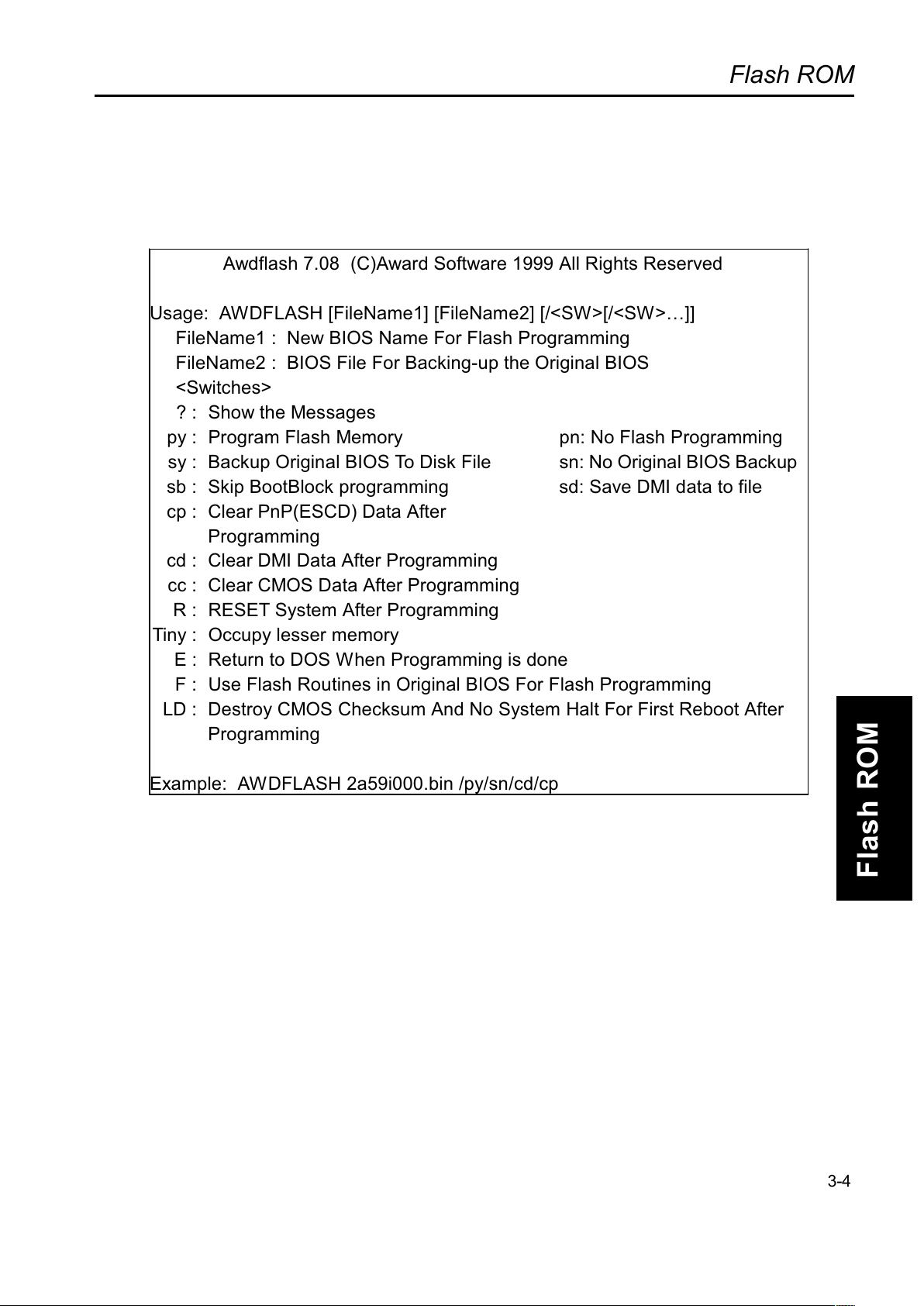
Flash ROM
Flash ROM
Awdflash 7.08 (C)Award Software 1999 All Rights Reserved
Usage: AWDFLASH [FileName1] [FileName2] [/<SW>[/<SW>]]
FileName1 : New BIOS Name For Flash Programming
FileName2 : BIOS File For Backing-up the Original BIOS
<Switches>
? : Show the Messages
py : Program Flash Memory pn: No Flash Programming
sy : Backup Original BIOS To Disk File sn: No Original BIOS Backup
sb : Skip BootBlock programming sd: Save DMI data to file
cp : Clear PnP(ESCD) Data After
Programming
cd : Clear DMI Data After Programming
cc : Clear CMOS Data After Programming
R : RESET System After Programming
Tiny : Occupy lesser memory
E : Return to DOS When Programming is done
F : Use Flash Routines in Original BIOS For Flash Programming
LD : Destroy CMOS Checksum And No System Halt For First Reboot After
Programming
Example: AWDFLASH 2a59i000.bin /py/sn/cd/cp
3-4
Page 78
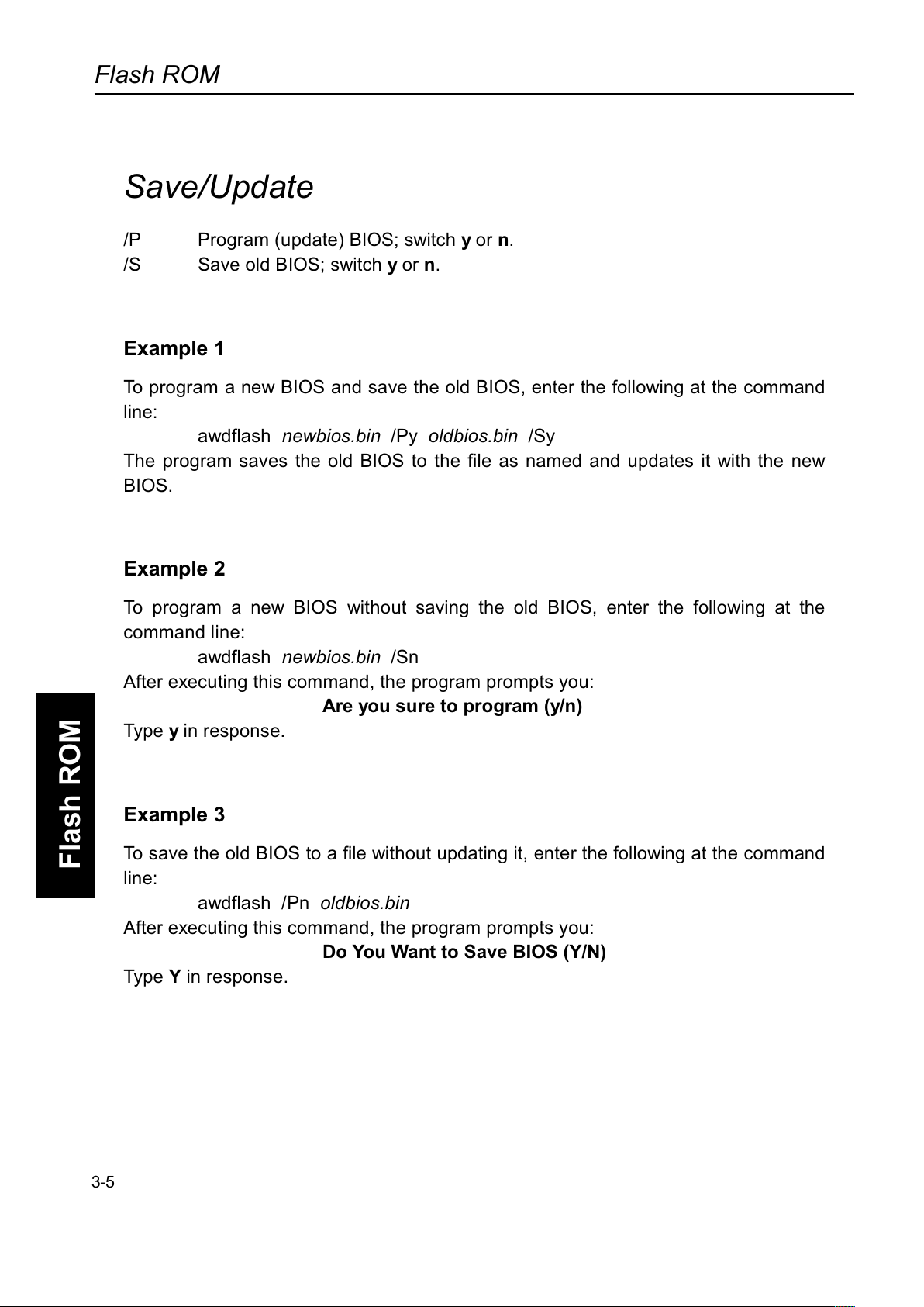
Flash ROM
Flash ROM
Save/Update
/P Program (update) BIOS; switch y or n.
/S Save old BIOS; switch y or n.
Example 1
To program a new BIOS and save the old BIOS, enter the following at the command
line:
awdflash
newbios.bin
/Py
oldbios.bin
/Sy
The program saves the old BIOS to the file as named and updates it with the new
BIOS.
Example 2
To program a new BIOS without saving the old BIOS, enter the following at the
command line:
awdflash
newbios.bin
/Sn
A
fter executing this command, the program prompts you:
Are you sure to program (y/n)
Type y in response.
Example 3
To save the old BIOS to a file without updating it, enter the following at the command
line:
awdflash /Pn
oldbios.bin
A
fter executing this command, the program prompts you:
Do You Want to Save BIOS (Y/N)
Type Y in response.
3-5
Page 79

Flash ROM
Flash ROM
Clear Data
The Award flash utility version 7.08 and above has three additional command line
parameters:
/CC Clear CMOS.
/CP Clear PnP data (ESCD)
/CD Clear DMI data
3-6
Page 80

Flash ROM
Flash ROM
(This Page Intentionally Left Blank for Notes)
 Loading...