

Page 1
Rio Grande
Digital Temperature Controller
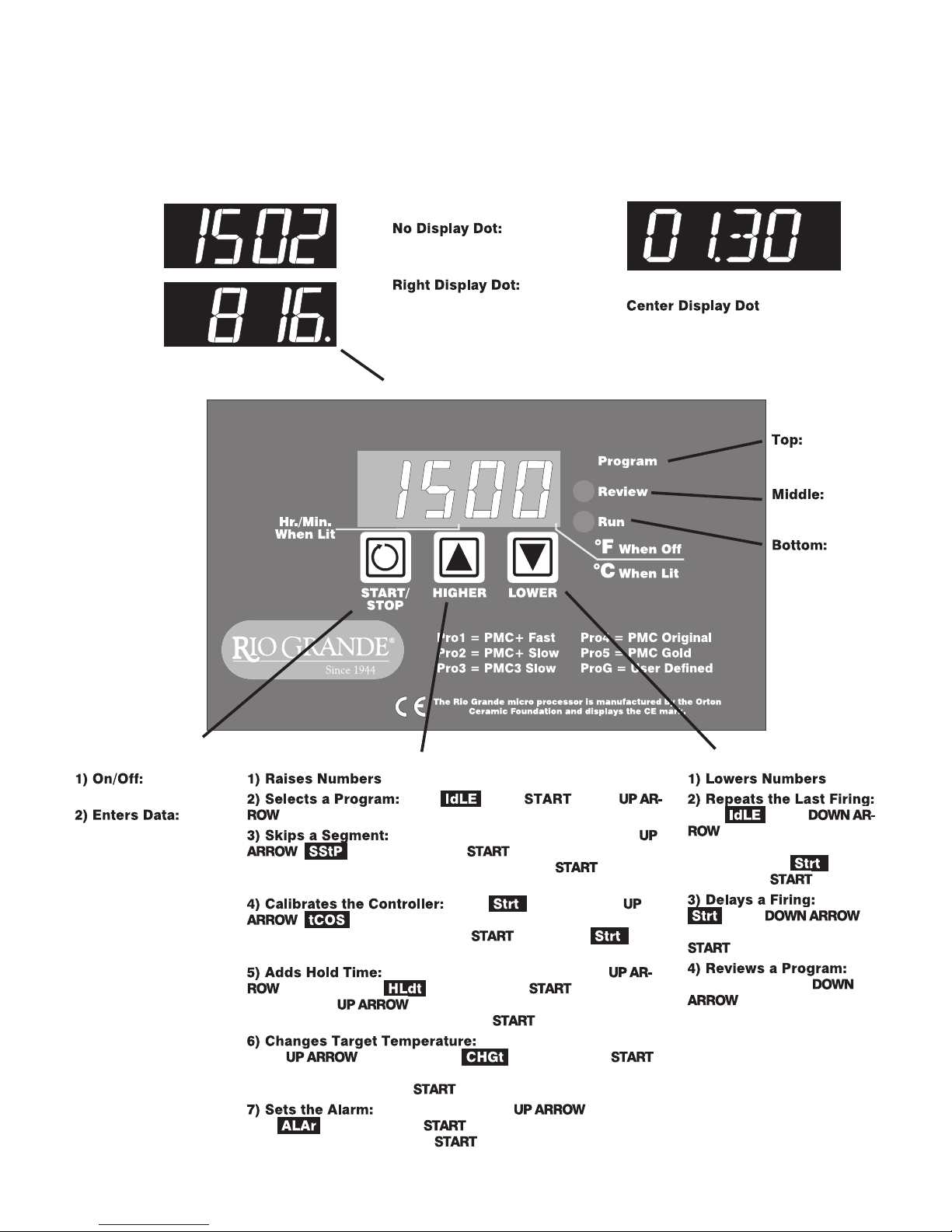
°F
°C
Temperature Display
Tempera
ture display is in °F.
Temper
ature display is in °C.
See page 9 for instructions on
selecting °F and °C.
Display Dot
-
-
Time Display
: Separates
hours from minutes. Example:
Display shown above is 1 hour
and 2 minutes
Indicator
Lights
On during
programming.
On during
program review.
Blinks dur-
ing firing.
START/STOP Key
Starts and
stops a firing.
Press
after each programming
step.
Up Arrow Key
From press .Press
to select a program.
During a User Defined firing, press the
. will appear. Press . The current segment
ramp or hold number will appear. To skip, press again.
Page 6
At the display, press
. will appear. Use arrow keys to calibrate the con
troller to fire hotter or cooler. Press to return to .
Page 9
During a User Defined firing, press
repeatedly until appears. Press .Eachtime
you press the , the hold time for the current segment
will increase by 5 minutes. Then press .Page6
During a User Defined firing,
press repeatedly until appears. Press .
Use the arrow keys to change the target temperature for the cur
rent segment. Then press .Page6
During a firing, press repeatedly
until appears. Press . Use the arrow keys to change
the alarm temperature. Press .Tosilencethealarm,press
any key. Page 7
Down Arrow Key
From press
. The program you have
selected will appear one step
at a time. When ap
pears, press .Page3
-
-
press .
Enter delay time. Press
.Page3
During firing, press
. The program you
entered will appear one step
at a time. Page 3
-
From
Page 2
Contents
Safety
General Guidelines . . . . . . . . . . . . . . . . . . . . 3
Time and Temperature Display . . . . . . . . . . . . . . . . . . 3
Operation Begins from the
Display . . . . . . . . . . . . . . . . . . . . . . . . . . . . . . . . . 3
Thermocouple Inspection . . . . . . . . . . . . . . . . . . . . . . . 3
A Rapid Way to Scroll Numbers . . . . . . . . . . . . . . . . . . 3
Program Review & Repeat Firing . . . . . . . . . . . . . . . . . 3
Delay . . . . . . . . . . . . . . . . . . . . . . . . . . . . . . . . . . . . . . . . 3
Power Failures . . . . . . . . . . . . . . . . . . . . . . . . . . . . . . . . 3
Selecting and Firing a PMC Program . . . . . . 4
Message: Firing Completed . . . . . . . . . . . . . . . 4
Thunder Storms and Power Surges . . . . . . . . . . . . . . . 4
Selecting a Program . . . . . . . . . . . . . . . . . . . 4
PMC Programs Stored in Memory . . . . . . . . . . . . . . . . 4
Rate . . . . . . . . . . . . . . . . . . . . . . . . . . . . . . . . . . . . . . . . . 5
Hold . . . . . . . . . . . . . . . . . . . . . . . . . . . . . . . . . . . . . . . . . 5
Temperature Over-Shoot . . . . . . . . . . . . . . . . . . . . . . . 5
User Defined Programs . . . . . . . . . . . . . . . . 5
Theory of Operation. . . . . . . . . . . . . . . . . . . . . . . . . . . . 5
Advanced Features . . . . . . . . . . . . . . . . . . . . 6
Skip Segment . . . . . . . . . . . . . . . . . . . . . . . . . . . . . . . . . 6
Add Hold Time. . . . . . . . . . . . . . . . . . . . . . . . . . . . . . . . 6
Editing the Current Segment Target Temperature
During Firing . . . . . . . . . . . . . . . . . . . . . . . . . . . . . . . . . 6
The Alarm . . . . . . . . . . . . . . . . . . . . . . . . . . . . . . . . . . . . 7
Lost Wax Burnout . . . . . . . . . . . . . . . . . . . . . 7
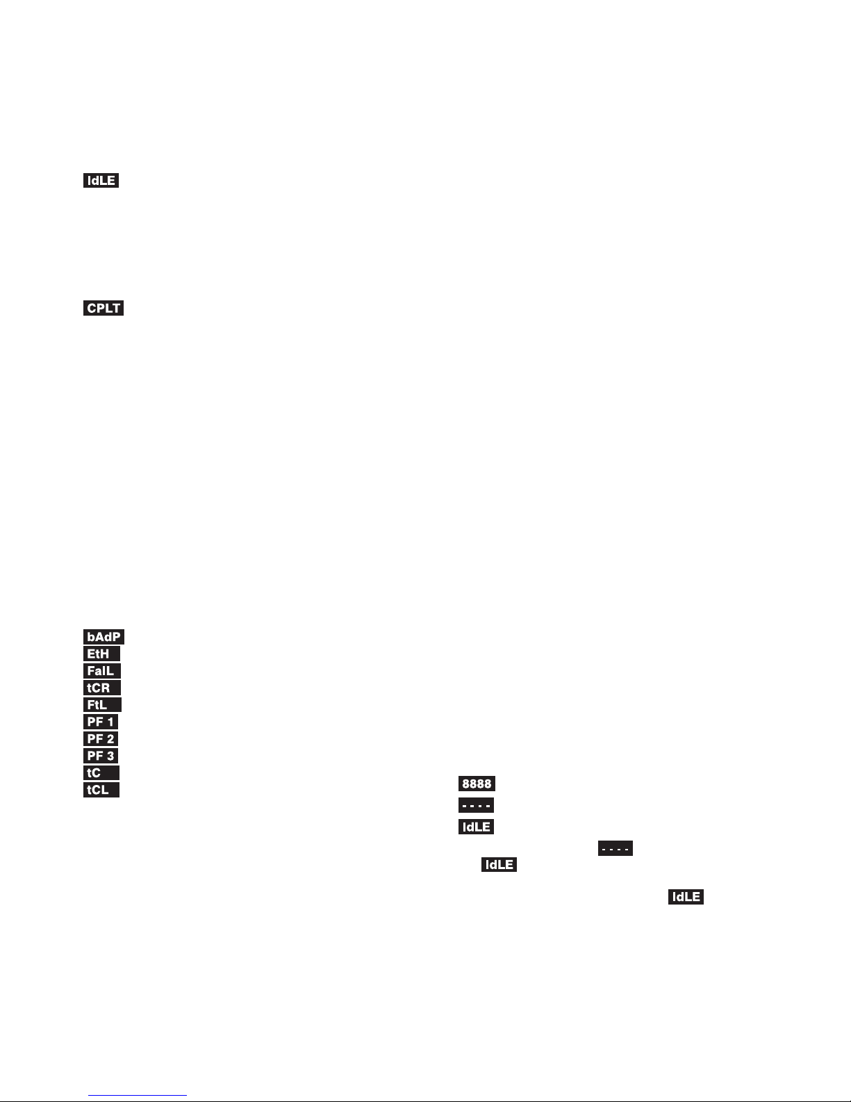
Error Messages. . . . . . . . . . . . . . . . . . . . . . . 8
/ Bad Programming . . . . . . . . . . . . . . . . . . . . . . 8
/ Electronics Too Hot. . . . . . . . . . . . . . . . . . . . . 8
/ Thermocouple Failure. . . . . . . . . . . . . . . . . . . 8
/ Thermocouple Reversed . . . . . . . . . . . . . . . . . 8
/ Fired Too Long . . . . . . . . . . . . . . . . . . . . . . . . 8
/ Power Failure. . . . . . . . . . . . . . . . . . . . . . . . . . . 8
/ Power Failure. . . . . . . . . . . . . . . . . . . . . . . . . . . 9
/ Power Failure. . . . . . . . . . . . . . . . . . . . . . . . . . . 9
/ Thermocouple Failure . . . . . . . . . . . . . . . . . . . 9
/ Thermocouple Lag. . . . . . . . . . . . . . . . . . . . . . 9
Calibrating the Controller . . . . . . . . . . . . . . . 9
Selecting °F or °C Display . . . . . . . . . . . . . . . 9
Display Messages. . . . . . . . . . . . . . . . . . . . 10
Trouble Shooter . . . . . . . . . . . . . . . . . . . . . 10
Problem: Controller display is blank. No heat in kiln.
. . . . . . . . . . . . . . . . . . . . . . . . . . . . . . . . . . . . . . . . . . . . 10
Problem: Controller display turns on.
No heat in kiln. . . . . . . . . . . . . . . . . . . . . . . . . . . . . . . . 11
Problem: Kiln switch box ½ amp fuses keep blowing.
. . . . . . . . . . . . . . . . . . . . . . . . . . . . . . . . . . . . . . . . . . . . 11
Shorthand Instructions . . . . . . . . . . . . . . . . 12
The warranty on your Rio Grande
controller does not cover damage from
overfiring, regardless of the
circumstances. It is the operator’s
responsibility to make sure the kiln turns
off at the proper time.
G
When the kiln is not in use, disconnect the
power.
G
Do not leave the kiln unattended, especially near
the expected shut-off time.
G
Wear firing safety glasses when looking into the
firing chamber of a hot kiln.
G
Do not touch hot sides of kiln. Keep unsuper
vised children away.
G
Install your kiln at least 12 inches from any wall
or combustible surface.
G
Do notopen lid ordooruntil kiln hascooled and
all switches are off.
G
Fire only in a well-ventilated, covered and protected area away from combustible materials.
G
Keep cordset away from hot sides of kiln or furnace.
G
DANGEROUSVOLTAGE!Donottouchheating elements with anything. Disconnect before
servicing.
Which Instructions Apply to
Your Controller
When you first connect the power, thecontrollerwill dis
play these messages, one after the other:
or a software code
If your controller shows instead of a software code
before appears, then thecontrollerincludes only Skip
Segment from "Advanced Features" on pages 6 - 7. If your
controller shows asoftwarecode before appears, then
the controller has all the features in this manual.
©2004, by Rio Grande IM-220/9-05
-
-
2 /
Page 3
General Guidelines
Time and
Temperature
Display
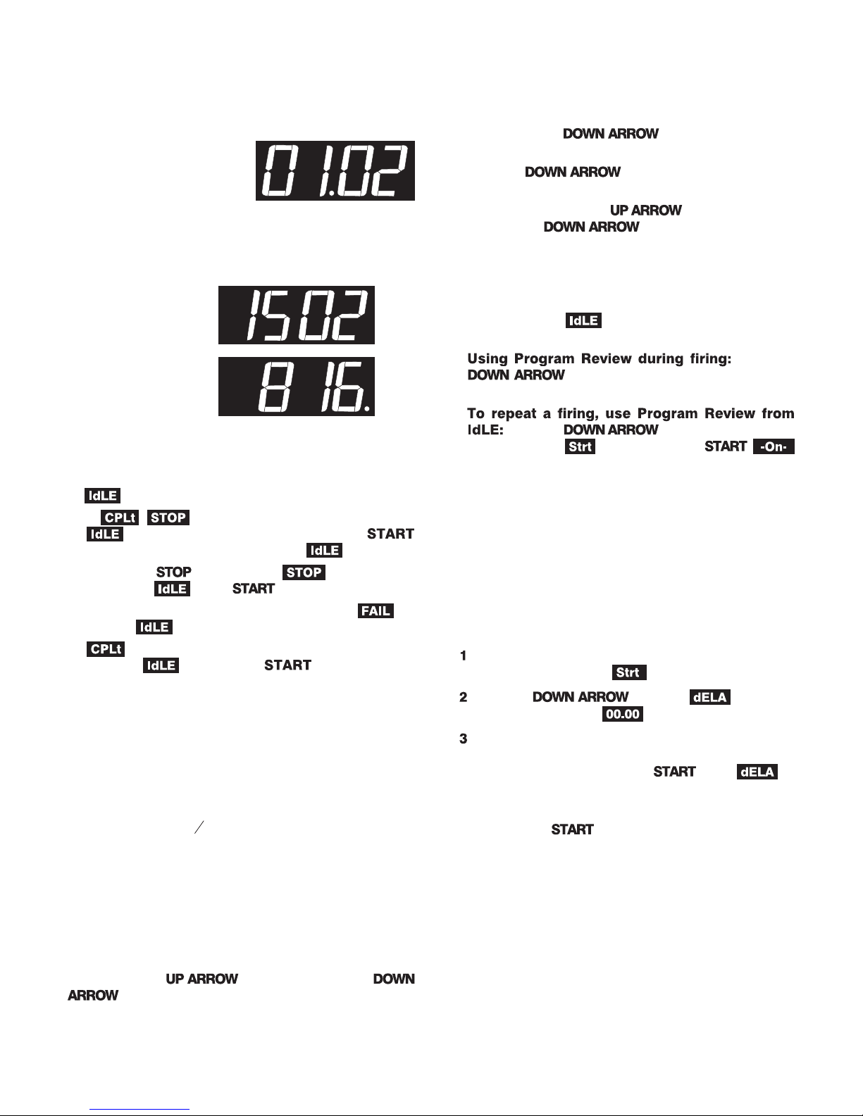
Center Dot: Time
A centerdotappears during
time display. It separates
hours from minutes.(Example: 1 hour,30 minutes displays
as 01.30.) During temperature display, the dot disappears.
Single Right-Hand
Dot: °C
When temperatureis
displayed in °C, a dot
appears in the lower
right. In °F display, it
disappears. You can
choose between Fahr
enheit and Celsius dis
play. See page 9.
-
-
Operation Begins from the
IdLE Display
must appear before you can fire the kiln.
I
If , , or other message appears instead of
when thekiln is first turned on, pressthe
key (the key with the circular arrow). will appear.
I
If youpress during afiring, will appear. To
get back to , press again.
I
If the display shows an error message such as instead of , see page 8.
I
(firing completed) appears at the end of a firing.
To make appear, press .
Thermocouple Inspection
The small rod protruding into the firing chamber is the
temperature sensor, or thermocouple.
Caution: Bumping the thermocouple can push it
out of the firing chamber. This could cause an
overfire!
I
A 1/8”diameterthermocouple shouldextend intothefir
ing chamber ½” -
I
A ¼” diameter thermocouple should extend into the fir
ing chamber 1” or more.
I
Keep shelves, posts and ware 1” - 1 ½” away from the
thermocouple.
5
”.
8
A Rapid Way to Scroll Numbers
During programming, hold an arrow key down several
seconds,andnumbers willbegin toscroll rapidly.Ordinarily,
you would press to raise a number and
to lower it. But sometimes it is faster to press the
°F
°C
opposite key.This is becausethenumbers scroll below0000
to the highest number, and vice versa. Examples:
I
To program a 99.59 hour Hold when the display shows
00.00, press the once.
I
To program a FULL rate when the display shows 0000,
press the once.
I
To program a temperature of 200°F when the display
shows 1800°F, press the . That is fasterthan
pressing the .
Program Review & Repeat Firing
Program Review lets you checkthat the information pro
grammed into the controller is correct. Program Review
shows thevalues forthe programinactive memory.Use Pro
gram Review from to repeat the last program you
fired.
I
key. The rate, temperature, hold, etc.
will display one after the other. Firing will continue.
I
Press the key. Afterrate, temper
ature, hold, etc., will appear. Press .
will appear,and thekilnwill beginfiring theprogram just
reviewed.
Delay
Delay isa count-down timer.The kiln beginsfiring when
the timer runs outof time. Use Delayto fit afiring into your
schedule.
Caution: Forsafety,do not leavethe kiln aloneduring adelayor afiring. Wecannotguarantee yourkiln
against overfiring even though the controller is automatic.
After you have selected a program and the controller
is ready to begin firing, will appear.
Press the key once. will ap
pear, alternating with .
Use thearrowkeystoenterdelaytime. (The decimal
separates hours and minutes. Example: 1 hour 10
minutes = 01.10) Then press twice.
will appear, alternating with time left until the firing
-
-
begins.
Note: Press during delay to end the delay
and begin the firing. The maximum delay is 99
hours and 59 minutes.
Power Failures
After a power failure, the controller will continue firing
provided that:
I
The kiln temperature is above 212°F/100°C when the
power comes back on.
I
The temperature dropped no more than 180°F/100°C
while the power was off.
-
-
Press the
-
-
/ 3
Page 4
Power Failure Messages
The power failed during a cooling segment, and
the kiln cooled past the target temperature while the power
was off.
The power failed during firing and kiln tempera
turewasbelow 212°F/ 100°Cwhen thepower cameback on.
The power failed during firing and temperature
dropped more than 180°F / 100°C by the time the power
came back on.
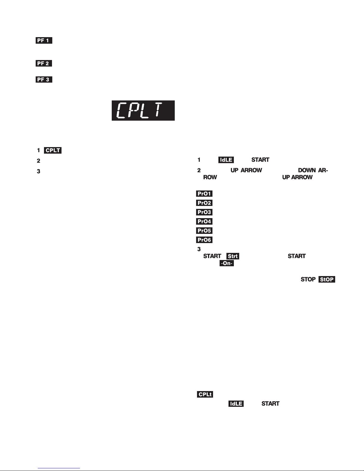
CPLT Message:
Firing Completed
When the firing has success
fully completed, the controller
will shutoff power tothe elementsand sound analarm for30
seconds.Thenthree messageswill cycleone afterthe other:
(complete)
Firing time in hours and minutes
The current kiln temperature
-
Thunder Storms and Power Surges
Unplug the kiln or disconnect the power when the kiln is
not in use, especially during thunder storms and in areas
with frequent power surges. If the kiln is part way through a
firing when a storm begins, it is probably okay to continue
the firing with close supervision. Do not leave the kiln unattended.
Selecting a
Program
PMC Programs Stored in Memory
Five PMC programs are stored in memory. You can also
program custom firings. Shown below are the heating rate,
temperature, and temperature hold time for each stored
program. (See “Theory of Operation,” next page, to learn
more about rate, temperature, and hold.)
Program 1: PMC Plus Fast
Heating rate per hour: Full
Temperature: 1650°F
Hold: 10 minutes
Program 2: PMC Plus Slow
Heating rate per hour: 1500°F
Temperature: 1470°F
Hold: 30 minutes
Program 3: PMC3 Slow
Heating rate per hour: 1500°F
Temperature: 1110°F
Hold: 45 minutes
Program 4: PMC Original
Heating rate per hour: Full
Temperature: 1650°F
Hold: 2 hours
Program 5: PMC Gold
-
Heating rate per hour: Full
Temperature: 1830°F
Hold: 2 hours
Program 6: User Defined program
Program custom rates, temperatures, and hold times.
Selecting and
Firing a PMC
Program
From , press .
Press the key (not the
). Each time you press the , a dif
ferent program will appear:
PMC Plus Fast
PMC Plus Slow
PMC3 Slow
PMC Original
PMC Gold
User Defined custom programming
When the PMC program you want appears, press
. will appear. Press to begin
firing. will appear and theRunindicator light
with begin blinking. The kiln is now firing.
To stop a firing before completion, press .
will appear, alternating with kiln temperature.
Note: Do not be concerned if your kiln makes a
clicking sound during firing. Kilns use relays to
power theelements. Therelays clickeach timetheir
electrical contacts come together.
Note: The kiln’s actual firing rate may be less than
the rate you programmed, depending on the kiln
model, available voltage, and density of load you are
firing.
When the kiln fires to completion, it will beep for 30 sec
onds. The display will show the following:
I
Firing time
I
Present temperature
I
To return to , press .
(fired to completion)
-
-
4 /
Page 5
User Defined
Programs
Theory of Operation
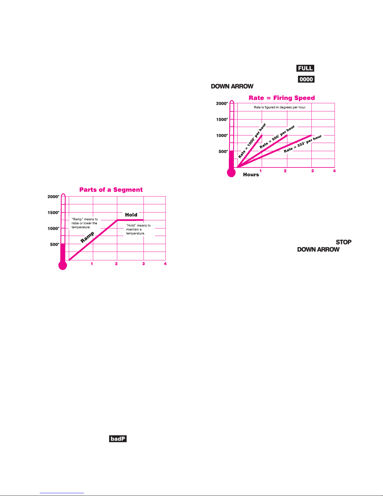
The temperatureyou arefiringto iscalled thetarget tem
perature. After the controller reaches the target tempera
ture, it can also hold that temperature.
The controller fires at acontrolledheating rate. The rate
is figured in degrees per hour. If you selected a rate of 100°
per hour, it would take 10 hours for the kiln to reach 1000°.
Rate is similar to “miles per hour.”
In summary, the controller does three basic tasks:
1) Itfires at acontrolledheating rate, or speed, measured
in degrees of temperature change per hour.
2) It fires to a target temperature.
3) It can hold the target temperature.
Rate
Each segment must include a rate, which is degrees of
temperature change per hour.
Thekilnwillfireatfullpowerwhentherateis
1799°F/999°C. Full power displays as .
-
-
Note: To enter full power from , press the
key once.
Hold
Hold is thelengthof time thatyou want thekilnto remain
at the target temperature. Hold is also called soak or dwell
time. Hold maintains a steady temperature for the length of
time you specify. You can use Hold in both heating up and
cooling down segments.
When Hold is set to 99.59 hours, the controller will remain atthattemperatureindefinitely,until you press .
To enter a 99.59 hour Hold, press the once
from 00.00 during programming.
The controllerfires insegments, orstages. Asegment isa
given heating rate to a target temperature. Shown above is a
segment with a target temperature of 1250° and a rate of
625°, with a hold of one hour.
Heating rate is figured in degrees per hour. The recom
mended heating rateforthematerial you are firingisusually
available from your supplier. It also varies depending on the
thickness of the material.
To figurehow longa firingsegment willtake, subtractthe
current temperaturefromthe target temperatureanddivide
the resultanttemperature bythe heatingrate. Inthe diagram
above, the firing time is 1250° - 80° (room temperature) =
1170 ÷625 = 1.87 hours.
The controller can fire up to 8 segments per firing in a
User Defined program. One segment is often all that is
needed, though.
After thecontrollerhas finished firingthe last segmentof
a User Defined program, it will turn off power to the kiln.
Note: If you enter a rate of 0000 in segment 1, or if
the target temperature in segment 1 is lower than
the current temperature, will appear in the
display.
Note: During firing, the display shows Hold temperature and time left in Hold.
Temperature Over-Shoot
When akilnis heated toofast, it mayover-shootthe target
temperature, especiallyin small kilnsat lower temperatures.
To avoid this, add an extra segment in a User Defined pro
gram to slow the firing.
-
/ 5
Page 6
User Defined
Advanced
Programming
Instructions
Note: You haveup to 8segments available in a User
Defined program. If you don’t need all 8, zero out
the unused segments. See step 6 below.
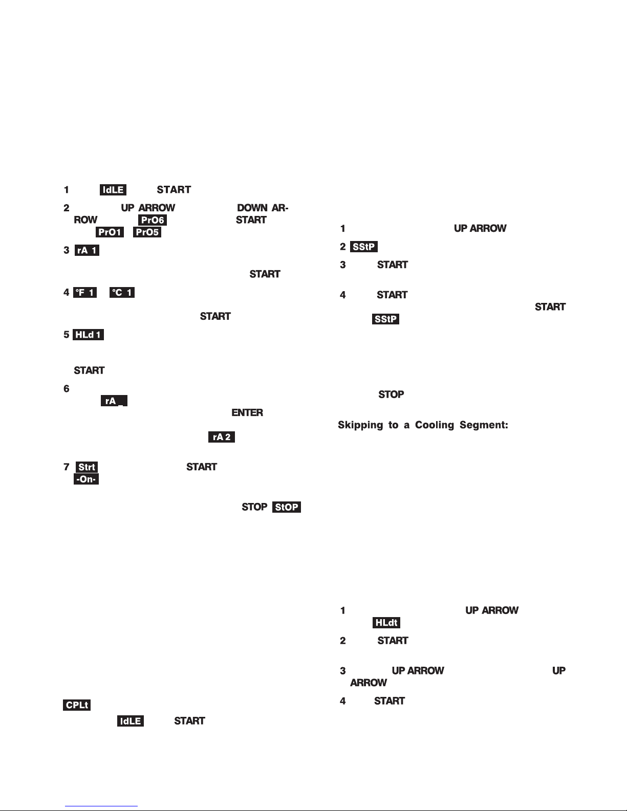
From , press .
Press the key (not the
). When appears, press . (Ig
nore - .)
will appear. Enter firing rate (temperature
change perhour)for segment1. (1° = slowest rate.
1799°F/999°C = full power.) Then press .
or and the target temperature from the
last firingwillappear.Usethearrowkeystochange
the temperature. Then press .
andthehold timefrom thelast firingwill ap
pear (Example: 1 hour 10 minutes = 01.10). Use
the arrow keys to change the hold time. Then press
. (No hold = 00.00.)
Continue entering values for the segmentsneeded.
When appears for the next segment that you
don’t need, select 0000. Then press . This
will zero out the remaining segments. (Example:
You needonly1 segment.When appears, enter 0000.)
will appear. Press to begin firing.
will appear and the Run indicator light with
begin blinking. The kiln is now firing.
To stop a firing before completion, press .
will appear, alternating with kiln temperature.
Note: Do not be concerned if your kiln makes a
clicking sound during firing. Kilns use relays to
power theelements. Therelays clickeach timetheir
electrical contacts come together.
Note: The kiln’s actual firing rate may be less than
the rate you programmed, depending on the kiln
model, available voltage, and density of load you are
firing.
When the kiln fires to completion, it will beep for 30 sec
onds. The display will show the following:
I
Firing time
I
Present temperature
I
To return to , press .
= Fired to completion
Features
Note: All thefeatures in thissectionare available in
a User Defined program. Thealarm is the only fea
ture in this section that is available in a PMC pro
gram. This is because PMC programs cannot be
altered.
Skip Segment
Skip Segmentworks only duringaUserDefinedfiring. It
-
-
jumps the firing from the current segment to the next one.
During firing, press the .
will appear.
Press . The current segment ramp or hold
number will appear.
Press again. (If you change your mind and
don’t wantto skip that segment,don’t press
after appears. Thefiringwillcontinue in the
same segment and the temperature will appear af
ter one minute.)
Skip Segmentskips totheramp of thenextsegment from
either arampor holdofthe currentsegment.(Skip Segment
does nothingduring the final segment.Toend the finalsegment, press .)
Skip Segment Example
You have programmed 1425°F for glass fusing, followed by a segment for
controlledcooling.Watching theglass throughthe peephole,
you notice that the glass edges haveroundednicelyat 1315°.
Use SkipSegment toend thefiring segmentand tobegin the
one for slow cooling.
Note: Make a note of the temperature at which the
glass fused. Program that temperature for the next
firing of that type of glass.
AddHoldTime
Add Hold Time works onlyduring a User Definedfiring.
It adds 5 minutes to a hold. It is designed for ceramists who
watch witness cones and for glass artists who inspect the
glass near the end of firing.
During a firing, press the repeatedly
until appears.
-
Press . The hold time for the current seg
ment will appear.
Press the . Each time you press the
, the hold time will increase by 5 minutes.
Press . Thenormal temperaturewill appear.
Note: Add Timewilladd 5 minutestoaholdevenif
no hold had been programmed.
-
-
-
-
6 /
Page 7
Editing the Current Segment Target
Temperature During Firing
While the kiln is firing a User Defined program, you can
change the target temperature of the current segment. You
can edit only the segment that is firing. So if the first seg
ment is the current one, you can edit only the first segment.
To edit othersegments, wait untilthe firing has progressed
to those segments.
Even if the current segment has already started its hold
time,youcan stilledit thesegment's targettemperature. You
can raiseor lowerthe targettemperature. Thecontroller will
go back out of holdand fire to thenewtargettemperatureat
the original rate. (You cannot edit the rate, however.)
During a firing, pressthe repeatedly un
til appears.
Press . Thetarget temperaturefor thecurrent
segment will appear.
Usethearrow keysto changethe targettemperature.
Press . The normal kiln temperature will ap
pear.
-
-
The Alarm
The alarm works in both PMC and User Defined programs.
While the kiln is firing, you can set the alarm, which
sounds when the kiln reaches the alarm temperature. Use
the alarm to alert you to check the fusing or slumping of
glass.
You canenter onlyone alarmtemperatureat atime. However, afterthe alarm beeps,you can set the alarmforanother
temperature, as many times as you want, during the firing.
Enteringanalarm temperatureautomatically erasesthe previous alarm temperature.
Note: The alarm temperature that you set during a
firing must be higher than the current display
temperature.
During a firing, pressthe repeatedly un
til appears.
Press . The current alarm temperature will
appear.
Usethearrow keysto changethe alarmtemperature.
Press . The normal kiln temperature will ap
pear.
To silence the alarm, press any key.
Analarmtemperature of32°F /0°C willturn offthe alarm.
-
-
Lost Wax Burnout
Caution: Only kilns with vent holes are designed
-
for lost wax burnout. However, you can use a kiln
without the vent hole provided that you open the
door ½” during venting.
Caution: Always use a wax tray.
Note: Theseinstructions applyto injectionwax that
melts at 200°F, not pattern waxes and plastics that
melt athighertemperatures.If smoke appears dur
ing wax elimination, turn off the kiln. Smoking wax
means the kiln fired hotter than 300°/148°C.
Overview
Lost wax casting is the process of carving a shape in wax,
making a mold, and then casting that shape in metal. After
the wax has been carved, a mold is made of the wax shape.
The mold is a negative image of the wax. The wax is later
melted out of the mold through hollow channels called
sprues.
Lost wax burnout is the process of preparing a casting
mold for the melted metal that will be poured into it. The
steps in lost wax burnout:
Melt the wax from the mold.
Remove waxfromthekiln before raisingthetemper-
ature higher than 300°F/148°C.
Harden the mold at high temperature.
Maintain themold atthecasting temperaturerecom-
mended for the type of metalthat will be poured into
the mold.
Caution: Prevent wax or carbon from contacting
the kiln’s walls and elements. Carbon build-up in
side akiln ruins the interior.Carbonconducts elec
tricity andcauses elementsto shortcircuit. Damage
to elements from contact with foreign materials is
not covered by warranty.
A Sample Program
Rate Temp.
Segment °F/°C °F/°C Hold
1 500/277 300/148 01.00
2 500/277 1350/732 01.00
3 450/250 800/426 02.00
Segment 1 heats the wax to 300°F/148°C and holds it for
one hour, allowing it to drip from the mold.
Segment 2 hardens the mold.
Segment 3 lowers temperature to 800°F/426°C, the typi
cal castingtemperature for silver.(Mosttypesof gold castat
900°F/482°C.)
-
-
-
-
Note: Casting temperature depends on the size of
the mold. The temperatures above are only a guide.
/ 7
Page 8
See your jewelry supply dealer for temperature
recommendations.
Error Messages
Burnout Instructions
Place a metal tray inside the kiln on three½” posts.
Place the mold on a wire mesh screen on top of the
tray. The mold’s sprue hole should be down. The
tray willcatch meltingwax asit dripsfrom thesprue
hole.
Keep the kiln’sventhole(s), if any, openduringwax
elimination. If the kiln has no vent hole, leave the
door open½”. Thisallows fumesto escapefrom the
kiln. Heatthe kiln to300°F/148°Cand hold it atthat
temperature for at least one hour.
Note: Do NOT heat the wax above 300°F/148°C.
Hold at 300°F/148°C for at least one hour. During
this hour, the wax will melt from the mold and drip
into the tray. If the kiln gets hotter than
300°F/148°C, the wax may smoke and deposit car
bon inside your kiln, causing expensive damage.
After one hour at 300°F/148°C, open the kiln. Re
move the mold andwax tray. Pour thewax from the
tray and leave the tray outof the kiln until your next
waxelimination.(Do notleave thetray inthe kiln!)
Heat themold tothetemperature recommended by
your jewelers’ supply house where you purchased
the mold material. This is usually around
1350°F/732°C.
Lower the temperature to the casting temperature
of the metal. Hold at that temperature until youare
ready tobegin casting.Remove themold withtongs.
Wear protective gloves and safety glasses.
Saving a Carbon-Damaged Kiln
If you followthe above directions, yourkiln should besafe
from wax damage. In some cases, a small amount of carbon
may formon thewalls overa periodof time.This isdue tothe
burning ofwax residuethat wasleft inthe mold.For thisrea
son we recommend that you periodically fire the kiln to
1500°F/815°C as follows:
Open the vent cover(s) or leave the door ajar ½”.
Fire the kiln empty to 1500°F/815°C at a rate of
300°F/166°C with a one hour hold (01.00).
-
-
bAdP / Bad Programming
The kiln will not fire the because the User Defined pro
gram justentered has1) arateof 0000in segment1, or2) the
target temperature in segment 1 is lower than the current
temperature.
EtH / Electronics Too Hot
The temperature of the electronic circuit board is above
185°F/85°C. This could damage the controller, so the firing
has been stopped. To prevent this, keep the firing room
cooler. Use better ventilation.
FaIL / Thermocouple Failure
The thermocouple, or temperature sensor, failed during
firing. Causes:
I
Defective thermocouple or disconnected/loose wires
I
Defective controller
I
Electrical noise
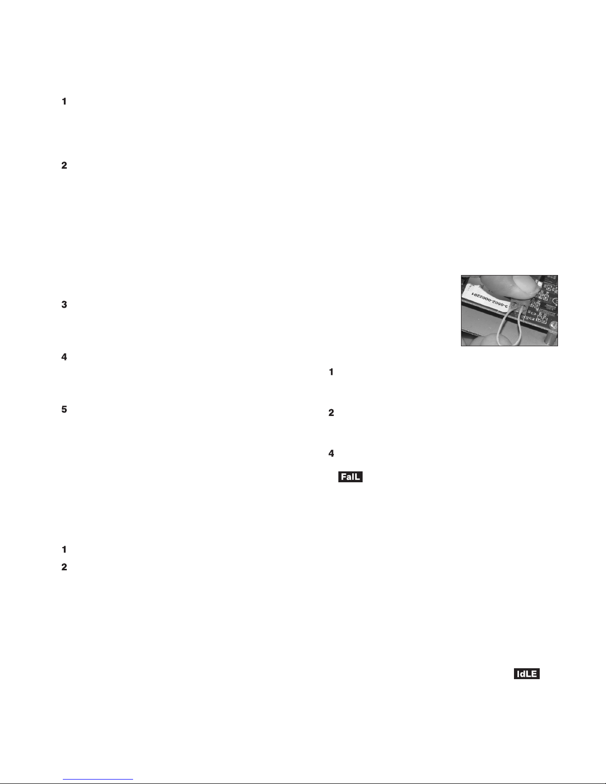
Thermocouple Paperclip Test
Check the thermocouple wire
connections. (See your kiln instruction manual.) If connections
are tight, perform this test:
UNPLUG the kiln or disconnect the power. Remove thecontroller. Remove thetwothermocouple
wires from the back of the controller.
Cut a thin paperclip in half. Insert a U-shaped
paperclip piece, or other piece of thin wire, where
you removed the thermocouple wires.
Plug inthekiln. Ifthecontroller displaysroomtem
perature, replace the thermocouple. If it shows
, replace the controller.
tCR / Thermocouple Reversed
-
Thermocouple lead wires are reversed. Check that the
thermocouple leadwiresare connected tothecorrect termi
nals. See your kiln's wiring diagram.
FtL / Fired Too Long
This message appears whenboth of the following condi
tions are met:
I
The temperature rise is less than 27°F/15°C per hour
I
The firing is 2 hours longer than programmed
See “Controller turns on. No heat in kiln,” page 11.
-
-
-
-
8 /
PF 1 / Power Failure
The power failed during a cooling segment, and the kiln
cooled past the target temperature while the power was off.
The kiln will not resume firing. To return to the dis
play, press any key.
-
Page 9
PF 2 / Power Failure
The power failed during firing and kiln temperature was
below 72°F / 40°C when the power came back on. The kiln
will not resume firing. To returnto the display, press
any key.
PF 3 / Power Failure
The power failed during firing and temperature dropped
morethan180°F /100°C bythe timethe powercame backon.
The kiln will not resume firing. To return to the dis
play, press any key.
tC / Thermocouple Failure
The thermocouple failed during the display. See
the "paperclip" test under "FaIL," page 8.
tCL / Thermocouple Lag
The heatingrateis slower than9°F/ 5°C perhourand the
kiln temperature is more than 100°F / 56°C away from the
programmed temperature. To return to the display,
press any key. Causes:
I
On kilnsthat use aportablecontroller, the thermocouple
fell out of the firing chamber.
I
A barespot onthethermocouple leadwires hastouched a
grounded object inside the kiln switch box causing the
thermocouple to short out.
I
low voltage and defective thermocouple.
will flash if you program a cooling segment tem-
perature that is below room temperature.
Check for worn or burned out elements, defective relays,
Selecting °F or °C
Display
The controllercandisplay temperature ineither°F or °C.
If yourcontroller shows asmall display dotin the lower right
corner of the display, the temperature shown is °C. No dot
means °F. To change temperature display:
UNPLUG kiln or disconnect power.
Remove thefour screwsthat holdthe controllerto the
frontofthe kiln.Carefully removethe controllerfrom
the kiln. Leave wires attached to the controller.
Look at the back of the controller. You will find a set
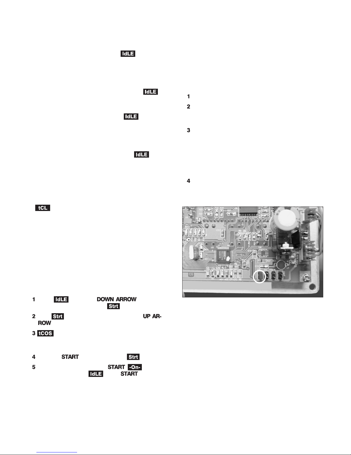
of connector pins near the bottom labeled “C/F.”
When a jumper is placed on the C/F pins, thedisplay
reads °F. When the jumper is removed, displayreads
°C. Removeorinsert the jumperasdesired. (You can
purchase thejumper from acomputersupply store if
necessary.)
Install the controller being careful not to jar compo
nents on the back of the controller against the kiln
case.
-
Calibrating the
Controller
You can calibrate the controller to fire up to 20°F/11°C
hotter or cooler than the zero factory setting.
From , press the key. After
rate, temperature, hold, etc., will appear.
With shown in the display, press the
key.
willappear.Press thearrow keysto changethe
controller temperature. (Lower numbers include a
"-".)
Press the key to return to the display.
To fire the controller, press . will ap
pear. Or to return to , press two more
times.
The C/F jumper terminal is on the back of the controller, circled above.
-
/ 9
Page 10
Display Messages
Trouble Shooter
The firing was stopped.
(Page 7) Readyfor you to enteran alarm temperature.
When the kiln reaches that temperature, the alarm will sound.
During a User Defined firing, you can change the tar
get temperature of a segment without having to first stop the
firing.
Fired tocompletion. Ifthe kilnis alreadyhotterthan the
programmed targettemperature when you begin firing,
will appear immediately after you begin firing.
(page 3) Delay is a count-down timer that starts the
kiln when the time runs out.
or (and temperature) (page 6) The target
temperature (thetemperature thatthe kilnwill fireto). Eachseg
ment in a User Defined program has a target temperature.
Full power firing rate. At this setting the kiln will fire at
its fastest rate. To select Full power, select a rate of
1799°F/999°Catthe promptin aUser Definedprogram. A
fast way to do this is to press the key once from
. will appear.
(pages 5 & 6) Hold time of a segment, shown in hours
and minutes. (i.e. 2 hours 15 minutes = 02.15.)
(Page 7) During a User Defined firing, you can extend
the holdtime toa segmentwithout havingto firststop thefiring.
(page 3) The controller is ready for you to enter a pro-
gram or to begin a repeat firing.
Firing has begun. A moment after appears, you
will hear the relay(s) clicking.
, , , , (page 4)
These are PMC programs stored in memory.
(User Defined Program) (page 5) Select this option to
program a custom firing.
, , etc. (Rate) (page 6) This appears in User
Defined programming foreach segment. 1,2, etc. aresegment
numbers. Enter the rate of temperature change for that seg
ment. Rate is figured in degrees of temperature change per
hour. Example:
A temperature rise of 100° in two hours = 50° rate.
A temperature drop of 200° in one hour = 200° rate.
(Skip Step)(page 5) This messageappears when you
press the key duringa UserDefined firing.If youpress
the key again,the firingwill skipto thenext segment.
The firing was stopped by pressing .
The "Ready to Start" message appears after program
ming afiring. Press to beginfiring. ControllerCalibration
(press the ) and Delay (press the )
are accessed from the message.
(Page 9) Calibrate the controller to fire hotter or
cooler.
Problem: Controller display is blank.
No heat in kiln.
I
Is the kiln connected to the power?
I
-
-
-
-
Has the circuit breaker tripped or fuse blown?
I
Is power reaching the wall receptacle?
Test with a voltmeter or test light if you are not sure.
I
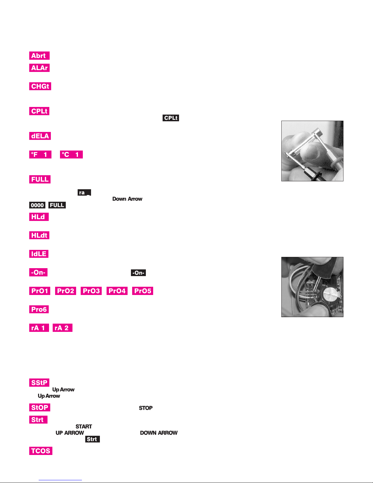
Has the kiln switch box ½ amp fuse blown?
The kiln’s ½ amp fuse is lo
cated in the kiln switch box. Re
-
move bypressingthefuseholder
and turning counter-clockwise
half a turn. Check the fuse by
placing theprobes of an ohmme
ter on the ends of the fuse. If the
ohmmeter reads less than an
ohm (digital meter) or reads 0
ohms (analog meter), the fuse is
okay. If the reading is OPEN (digital meter) or infinity/no
needle movement (analog meter), the fuse is bad. Replace
ment fuse:
AGC 1/2 A 250V AC
I
Is the controller receiving power? Test the power INPUT connections on the back of the controller with a
voltmeter.
Controller Power Input Test
Unplug thekiln. Removethe 4
screws holding the controller
faceplate to the switch box. Lift
faceplate out of box and let the
board hang on the box with the
back of the board facing you.
Plug thekiln backin. Touchvolt
meter probes (in AC mode) to
both INPUT connections (the
white and orange wires).
Caution: Do not let the back of the board touch a
grounded object. Make sure the voltmeter is in the
AC mode when placing the probes on INPUT con
nections.
Controller Power Input Test Result: No voltage
UNPLUG kiln. Check the switch box for disconnected
wires between the cord, transformer, and controller. If wir
ing is okay, replace the transformer.
Controller Power Input Test Result: 20 - 24 volts AC
Correct current is reaching the board from the trans
former. But since the board is not lighting up, it is probably
defective. Return the controller for repair or replacement.
Controller Power Input Test Result: less than 20 volts
Did you recently replace the transformer? It may be the
wrong voltage. The voltage is below 20, which is not enough
-
-
-
-
Page 11
power forthecontroller. Tofind outthecause oflow voltage,
continue below:
Controller Input Test #2
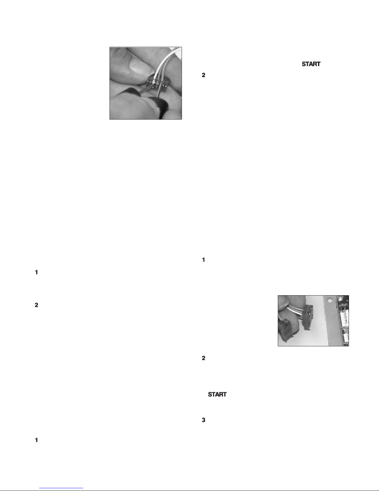
The back of the board is
still facing you and the kiln is
plugged in. Remove the IN
PUT plug, which is the
white, orange, and blue
wires, from the back of the
controller.Toucha voltmeter
probe to the white wire and
the other probe to theorange
wire.
Input Test #2 Result: Less than 20 Volts AC
There aretwopossible reasons: 1)Low voltage atthe wall
receptacle; 2) defective transformer. If wall receptacle volt
age is correct, replace the transformer.
Input Test #2 Result: 20 - 24 Volts AC
Thetransformeris sendingcorrect voltageto thecontrol
ler. Yetwhen the INPUTplugwas connected tothecontrol
ler, voltage was less than 20. This means the controller is
draining the voltage and may be defective. Return the con
troller for repair or replacement.
-
Problem: Controller display turns on.
No heat in kiln.
I
Is the relay making its normal clicking sound?
Yes, the relay is clicking.
Test the elements with an ohmmeter:
Element Resistance Test
UNPLUG kiln/disconnect the power. Open the
kiln’s switchbox. Makesure thewires connectingthe
relay to the elements are secure. If connections are
okay, continue to step 2:
Touch the ohmmeter leads to the two element con
nectors of each element. A no-needle-movement
reading onan analogmeter, orOPENon adigitalme
ter, indicates a broken element.
If the elements check out okay, replace the relay.
Note: To replace relay, see your kiln’s instruction
and service manual.
No, the relay is not clicking.
We know the controller is receiving voltage, because the
display islit. Butthe voltagefrom thetransformer maybe too
low to power the relays. Perform the “Controller Power In
put Test,” page 10. If your controller passes the input test,
perform the “Controller Power Output Test”:
Controller Power Output Test
Is thecontrollersendingvoltagetotherelay? Test OUT
PUT with a voltmeter:
UNPLUG the kiln/disconnect the power. Remove
the 4 screws holding the controller faceplate to the
-
-
switch box. Lift faceplate out of box and let the con
troller hang ontheoutside of theboxwith the backof
the boardfacing you.Thenplug thekiln backin.Pro
gram the controllerto fire to 1000°F at FULL rate in
User Defined program mode. Press .
Put the voltmeter in DC mode. (It must be in DC
mode when testing OUTPUT voltage.) Touch
probes to the red wire and black wire connections.
Measure voltage when the relay clicks on.
Output Test Result: No voltage at red and black wires
The controller is not sending power to the relay. Return
the controller for repair or replacement.
Output Test Result: 10 - 14 v. at red and black wires
The controller is sending correct power to the relay. Un
plug kiln/disconnect power. Remove the kiln switch box.
Look for disconnected wires between the controller, relay
and elements.Checkthe wiringdiagramto besurewires are
connected to the correct terminals.Be sure connections are
-
tight. If the wiring is okay, replace the relay.
-
-
Note: To replace relay, see your kiln’s instruction
and service manual.
Problem: Kiln switch box ½ amp
fuses keep blowing.
I
What size fuse are you using? Correct fuse:
AGC ½ A 250V AC.
Ifthefuse isthe correctsize, performthe followingtest:
Kiln Switch Box ½ Amp Fuse Power Test
UNPLUG the kiln/disconnect the power. Remove
the 4 screwsholdingthe controllerboardfaceplate to
the switch box. Lift faceplate out of box and let the
board hangontheoutsideoftheboxwiththeback of
the boardfacing you.Thenplug thekiln backin.Dis
connect both wire plugs
from the back ofthe con
troller. Apply power to
kiln. If fuse blows, re
place thetransformer.(If
the fuse does not blow,
the problem is a board or
relay. Go to step 2.)
Connect the INPUT plug (orange, blue, and white
wires) to the board again. Leave off the OUTPUT
wire plug (the one with the red, green and black
wires). Program the controller to fire to 1000°F at
-
-
FULL rate in User Defined firing mode. Press
. If the fuse blows, replace or service the
board. (If the fuse does not blow, the problem is
causedbya shortin thecoil ofa relay.Go tostep 3.)
UNPLUG kiln/disconnect power. Reconnect the
OUTPUT wire plug. Reinstall the board in the
switch box. Replace the relay.
-
-
-
-
-
-
/ 11
Page 12
Shorthand Instructions
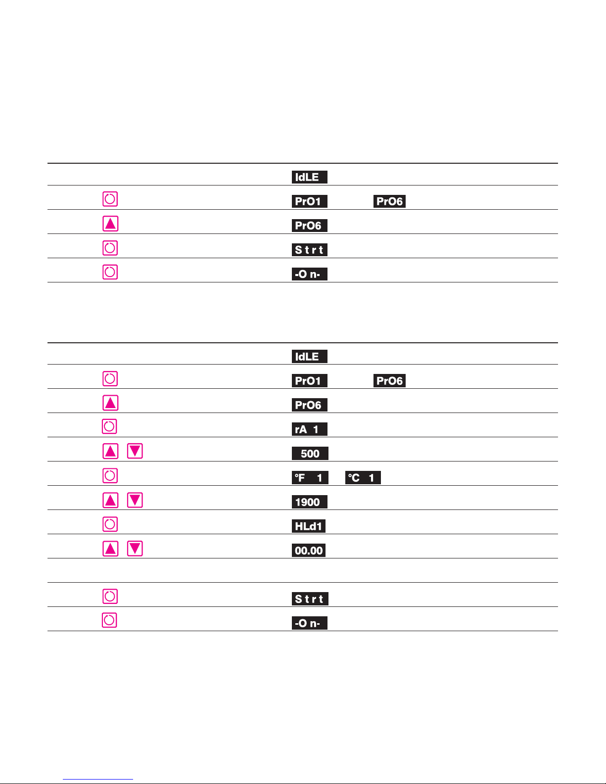
To avoid confusion,readthe manual beforeusing these quickshorthandinstructions. After pressingthekeys in theleftcol
umn, the message in the center will appear.
Selecting a Stored PMC Program
Keys to Press Shown in the Display
through
(Not Down Arrow) (SelectProgram1,2,3,4,or5)
The kiln is now firing.
The User Defined Program
Keys to Press Display
-
(Not Down Arrow) Select PrO6
Enter Segment 1 Rate (Sample rate)
Enter Temperature (Sample temperature)
Enter Hold Time (Or hold time)
First segment not needed: enter a rate of 0000.
through
or
The kiln is now firing.
12 /
 Loading...