

Page 1

5000
DIGITAL
INDICATOR
Modbus
Communications
Manual
For use with Software
Versions 4.xx
5000-603.doc Rev 1.0
Page 2

RANGER 5000 - Communications Manual Rev 1.0
1. INTRODUCTION ................................................................................................................... 1
CONNECTION OF THE 5000 NETWORK............................................................................ 2
2.
2.1 RS232 C
2.2 RS485/RS422 C
ONNECTION
ONNECTION
......................................................................................................................2
..........................................................................................................2
3. MODBUS REGISTER DEFINITIONS FOR THE 5000.......................................................... 3
OLDING REGISTERS
3.1 H
NPUT REGISTERS
3.2 I
OMMANDS (IMPLEMENTED AS COILS
3.3 C
......................................................................................................................3
...........................................................................................................................3
)..........................................................................................4
4. MODBUS ASCII COMMUNICATIONS.................................................................................. 5
NTRODUCTION
4.1 I
RAMING
4.2 F
DDRESS FIELD
4.3 A
UNCTION FIELD
4.4 F
ATA FIELD
4.5 D
4.6 LRC F
4.7 E
IELD
XCEPTION RESPONSES
...............................................................................................................................5
........................................................................................................................................5
..............................................................................................................................5
............................................................................................................................5
...................................................................................................................................5
.....................................................................................................................................5
..................................................................................................................6
5. COMMAND DETAILS............................................................................................................ 7
5.1 F
5.2 F
5.3 F
5.4 F
5.5 F
5.6 F
5.7 F
UNCTION
UNCTION
UNCTION
UNCTION
UNCTION
UNCTION
UNCTION
EAD COIL STATUS
01: R
EAD HOLDING REGISTERS
03: R
EAD INPUT REGISTERS
04: R
ORCE SINGLE COIL
05: F
RESET SINGLE REGISTER
06: P
ORCE MULTIPL E COILS
15 F
RESET MULTIPL E REGISTERS
16 P
.................................................................................................7
....................................................................................8
..........................................................................................9
..............................................................................................10
.....................................................................................10
.........................................................................................11
................................................................................12
1. Introduction
This manual details the Modbus communications option of the Ranger 5000.
The Modbus communications option is a separate software license that may
be installed Ranger at the time of purchase or installed afterwards via the use
of the CONFIG menu. Details of the 5000 licensing options and how to install
them may be found in the Reference Manual.
The Modbus protocol was originally developed for use by Modicon
programmable controllers but has been adopted by many manufacturers as a
common protocol standard.
The Modicon standard specifies two transmissions modes: ASCII or RTU.
The 5000 supports the ASCII transmission mode only.
Information in this manual details the underlying communications protocol but
in practice this is generally looked after by the PLC directly. All that is
normally required for setup is to specify the addresses of the registers of
interest to your application. Much of the data from the 5000 is implemented
as 2 consecutive registers to make up a complete 32 bits of data. However
unless the 5000 has been setup with a fullscale of more than 30000 units it is
possible to use the lower order 16 bits contained in a single register.
1
Page 3
RANGER 5000 - Communications Manual Rev 1.0
2.
Connection of the 5000 Network
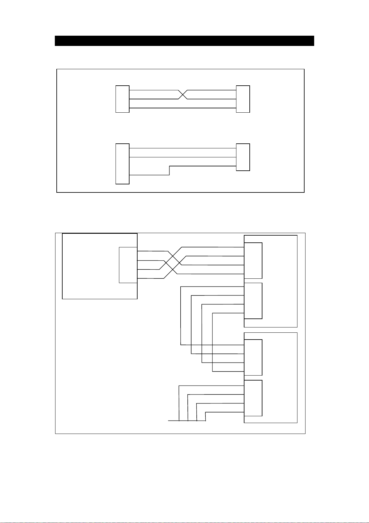
2.1 RS232 Connection
PC
COM 1
DB9
PC
COM 2
DB25
Figure 1: Connection of a single 5000 unit to an IBM PC either using COM1 or
COM2 on the PC.
2.2 RS485/RS422 Connection
RS485/RS422
HOST
2 RXD
3 TXD
5 GND
2 TXD
3 RXD
7 GND
RA
RB
TA
TB
2 RXD
3 TXD
5 GND
2 RXD
3 TXD
5 GND
RA 6
RB 7
TA 8
TB 9
RA 6
RB 7
TA 8
TB 9
To 5000
SERIAL
1
To 5000
SERIAL
1
SERIAL
1
UNIT 1
SERIAL
2
TO NEXT UNIT
Figure 2: Connection of a RS485/RS422 network.
2
RA 6
RB 7
TA 8
TB 9
RA 6
RB 7
TA 8
TB 9
SERIAL
1
UNIT 2
SERIAL
2
Page 4

RANGER 5000 - Communications Manual Rev 1.0
3. MODBUS Register Defi ni tions for the 5000
The 5000 implements a number of holding registers, input registers and coils.
Generally all that is required to configure your MODBUS master to work with
the 5000 is to specify the address of the 5000 unit, and the addresses of the
registers that you are interested in. Following is a list of the 5000 MODBUS
registers.
3.1 Holding Registers
Holding Registers in the 5000 are as follows:
Register Contents
40001 Target 1 High 16 bits
40002 Target 1 Low 16 bits
40003 Inflight 1 High 16 bits
40004 Inflight 1 Low 16 bits
40005 Target 2 High 16 bits
40006 Target 2 Low 16 bits
40007 Inflight 2 High 16 bits
40008 Inflight 2 Low 16 bits
40009 Target 3 High 16 bits
40010 Target 3 Low 16 bits
40011 Inflight 3 High 16 bits
40012 Inflight 3 Low 16 bits
40013 Target 4 High 16 bits
40014 Target 4 Low 16 bits
40015 Inflight 4 High 16 bits
40016 Inflight 4 Low 16 bits
3.2 Input Registers
Input Registers in the 5000 are as follows:
Register Contents
30001 Unused (Always = 0)
30002 Reading Status
30003 Unused (Always = 0)
30004 Reading Error
30005 Displayed Reading High 16 bits
30006 Displayed Reading Low 16 bits
30007 Gross Reading High 16 bits
30008 Gross Reading Low 16 bits
30009 Net Reading High 16 bits
30010 Net Reading Low 16 bits
30011 Unused (Always = 0)
30012 Number of Batches or items in the total
30013 Total 1 High 16 bits
30014 Total 1 Low 16 bits
30015 Total 2 High 16 bits
30016 Total 2 Low 16 bits
30017 Peak Displayed Reading High 16 bits
30018 Peak Displayed Reading Low 16 bits
3
Page 5

RANGER 5000 - Communications Manual Rev 1.0
3.3 Commands (implemented as coils)
MODBUS Coils are used in the 5000 to implement specific operator
commands. A single coil is set to trigger the function. These coils are self
clearing once the function has been executed.
It is possible to configure the operation of the 4 remote keys (See the
Reference Manual for details of the available functions). Each of the remote
keys has a normal function triggered by a single press and a second function
which is triggered by a long 2 second key press. Coils 5 ..12 simulate the
operation of these physical buttons. In this way it is possible to operate these
extended functions of the 5000 without the need for the Setpoint accessory
card or the physical buttons.
The 5000 commands available as coils are as follows:
Coil Function
00001 Zero
00002 Tare
00003 Gross/Net
00004 Print
00005 Remote Key 1 function single press
00006 Remote Key 2 function single press
00007 Remote Key 3 function single press
00008 Remote Key 4 function single press
00009 Remote Key 1 function long press
00010 Remote Key 2 function long press
00011 Remote Key 3 function long press
00012 Remote Key 4 function long press
4
Page 6

4.1 Introduction
With Modbus ASCII transmission each 8 bit byte of the message is
transmitted as 2 ASCII Hex characters (‘0’ .. ‘9’, ‘A’..’F’) for each 4 bits
of the byte.
4.2 Framing
The ASCII message starts with a colon(:) character (ASCII 3A hex) and
ends with a carriage return line feed (CRLF) pair (ASCII 0D, 0A hex).
Delays of up to one second can elapse between characters in a
message. A typical message Frame is shown below:
RANGER 5000 - Communications Manual Rev 1.0
4. MODBUS ASCII Communications
START ADDRESS FUNCTION DATA LRC
CHECK
‘:’ 2 HEX
CHARS
2 HEX
CHARS
2* N HEX
CHARS
2 HEX
CHARS
4.3 Address Field
The Modbus protocol supports slave addresses in the range of 0 .. 247
but the 5000 supports slave addresses in the range of 0..31. The
address 0 is reserved for broadcast addressing, and the slave
addresses range from 1..31.
4.4 Function Field
Valid functions codes range from 1..255. The 5000 supports the
following functions:
01: Read Coil Status
03: Read Holding Registers
04: Read Input Registers
END
CRLF
05: Force Single Coil
06: Preset Single Register
15: Force Multiple Coils
16: Preset Multiple Registers
4.5 Data Field
The data field is constructed of pairs of hexadecimal digits. The size of
the data field depends on the message function
4.6 LRC Field
The Longitudinal Redundancy Check (LRC) is calculated on the
message contents excluding the leading colon and trailing CRLF
characters. The LRC is calculated by adding together each of the
5
Page 7

RANGER 5000 - Communications Manual Rev 1.0
bytes in the message, discarding any carries, and then two’s
complementing the result. The 8 bit LRC is sent as two hexadecimal
characters.
4.7 Exception Responses
Except for broadcast messages to which there is no response from a
slave unit, when the master sends a message there is an expected
response from the slave unit. However a number of different events
can occur which makes it impossible for the slave unit to respond in the
way expected.
If the masters message is corrupted and can’t be deciphered or if the
check sum is incorrect the slave unit ignores the message and the
master will timeout and try again.
If the slave receives a message that it can decipher but it cannot
respond to because it does not support that type of message or the
registers specified do not exist etc. then there is a standard exception
response to warn the master and prevent it from endlessly re-trying the
same errant message.
The format of an exception response is as follows:
START ADDRESS FUNCTION Exception
Code
‘:’ 2 HEX
CHARS
2 HEX
CHARS
2 HEX
CHARS
LRC
CHECK
2 HEX
CHARS
The Address is the slave’s address. The function field is the function
code of the master’s message with the most significant bit set to
indicate the exception status. For example function 03 hex becomes
exception 83 hex.
The exception codes supported by the 5000 are as follows:
01 ILLEGAL FUNCTION This function is not supported by the
5000.
02 ILLEGAL DATA
ADDRESS
The register address range is
outside the range of registers
supported by the 5000.
03 ILLEGAL DATA
VALUE
The data sent is out of range for the
particular registers that were
addressed.
END
CRLF
6
Page 8

RANGER 5000 - Communications Manual Rev 1.0
5. Command Details
5.1 Function 01: Read Coil Status
This function reads the status of the discrete coils in the 5000. All such coils
in the 5000 are implements as one-time commands and are internally
cleared. This function therefore always returns the OFF status for these coils.
The function is included to make the 5000 compatible with systems that insist
on reading the status of all coils automatically. Broadcast is not supported.
See section 3.3 page 4 for a list of all of the coils.
Here is an example of a command to read all 12 coils from the 5000.
Field Name Example (Hex)
Slave Address 02
Function 01
Data:
Starting Address Hi 00
Starting Address Lo 00
Number of points Hi 00
Number of points Lo 0C
Response
The status of each coil is returned as one bit per coil in the data field.
Here is an example of a response to the above query.
Field Name Example (Hex)
Slave Address 02
Function 01
Data:
Byte Count 02
Data (Coils 8..1) 00
Data (Coils 12..9) 00
7
Page 9

RANGER 5000 - Communications Manual Rev 1.0
5.2 Function 03: Read Holding Registers
This function reads the contents of holding registers (Addressed as 4xxxx) in
the slave. Broadcast is not supported.
Query
The query specifies the starting register and the number of registers to read.
Registers are addressed starting at zero - so register 40001 is addressed as
zero.
Here is an example of a request to read registers 40001 to 40002 from slave
address 2.
Field Name Example (Hex)
Slave Address 02
Function 03
Data:
Starting Address Hi 00
Starting Address Lo 00
Number of points Hi 00
Number of points Lo 02
Response
The contents of the response include the slave address and function so the
master can verify that the response is from the correct unit. Also included is a
byte count followed by the block of data requested.
Here is an example of a response to the above query.
Field Name Example (Hex)
Slave Address 02
Function 03
Data:
Byte Count 04
Reg 40001 Data Hi 00
Reg 40001 Data Lo 00
Reg 40002 Data Hi 03
Reg 40002 Data Lo E8
This example reads the full 32 bit contents of setpoint target 1 represented as
the two 16 bit registers 40001 and 40002. The target 1 value in this example
is 1000 kg or (000003E8 hex).
8
Page 10

RANGER 5000 - Communications Manual Rev 1.0
5.3 Function 04: Read Input Registers
This function reads the contents of the input registers (Addressed as 3xxxx) in
the slave. Broadcast is not supported.
Query
The query specifies the starting register and the number of registers to read.
Registers are addressed starting at zero - so register 30001 is addressed as
zero.
Here is an example of a request to read registers 30005 to 30006 from slave
address 2.
Field Name Example (Hex)
Slave Address 02
Function 04
Data:
Starting Address Hi 00
Starting Address Lo 04
Number of points Hi 00
Number of points Lo 02
Response
The contents of the response include the slave address and function so the
master can verify that the response is from the correct unit. Also included is a
byte count followed by the block of data requested.
Here is an example of a response to the above query.
Field Name Example (Hex)
Slave Address 02
Function 04
Data:
Byte Count 04
Reg 40001 Data Hi 00
Reg 40001 Data Lo 00
Reg 40002 Data Hi 29
Reg 40002 Data Lo 42
This example reads the full 32 bit contents of the current displayed reading
represented as the two 16 bit registers 30005 and 30006. The weight reading
value in this example is 10562 kg or (00002942 hex).
9
Page 11

RANGER 5000 - Communications Manual Rev 1.0
5.4 Function 05: Force Single Coil
This function forces a single coil in a slave unit. When broadcast (address =
0) the same coil is set in all units. Coils are addressed as 0xxxx.
Query
The query specifies the coil address and whether the coil is to be forced on or
off. Coils are addressed starting at zero - so coil 00001 is addressed as zero.
A data value of FF00 hex forces a coil on and a value of 0000 forces the coil
off.
Here is an example of a request to Tare the reading of slave address 2.
Field Name Example (Hex)
Slave Address 02
Function 05
Data:
Coil Address Hi 00
Coil Address Lo 02
Force Data Hi FF
Force Data Lo 00
Response
The normal response of a force coil request is to echo the full contents of the
message.
5.5 Function 06: Preset Single Register
This f unction sets the contents of holding registers (Addre ssed as 4xxxx) in
the slave. When broadcast (address = 0) the same register is set in all units.
Query
The query specifies the holding register and the data to be written to it.
Registers are addressed starting at zero - so register 40001 is addressed as
zero.
See Section 3.1 page 3 for details of the available holding registers.
Here is an example of a command to set register 40001 to 1500 kg on slave
address 2.
Field Name Example (Hex)
Slave Address 02
Function 03
Data:
Register Address Hi 00
Register Address Lo 00
Register Data Hi 05
Register Data Lo DC
Response
The normal response of the preset register command is to echo the full
contents of the message.
10
Page 12

RANGER 5000 - Communications Manual Rev 1.0
5.6 Function 15 Force Multiple Coils
This functions performs the same task as function 5 but allows multiple coils
to be set and reset in the same message. In the 5000 it is only possible to set
one coil at a time so this message is not strictly necessary as it is easier to
use Function 05. However not all systems implement the forcing of a single
coil using Function 05, some use function 15. When broadcast the same
coils are forced in every slave unit.
Query
See Section 3.3 page 4 for details of the available coils.
Here is an example of a command to set coil 1 and trigger a zero command.
Field Name Example (Hex)
Slave Address 02
Function 0F
Data:
Coil Address Hi 00
Coil Address Lo 00
Number of coils Hi 00
Number of Coils Lo 0C
Number of bytes 02
Data (Coil 8..1) 01
Data (Coil 12..9) 00
Response
The normal response of the force multiple coils command is to send the slave
address, function code, starting address and quantity of coils forced.
Here is an example of a reply to the above command.
Field Name Example (Hex)
Slave Address 02
Function 0F
Data:
Coil Address Hi 00
Coil Address Lo 00
Number of coils Hi 00
Number of Coils Lo 0C
11
Page 13

RANGER 5000 - Communications Manual Rev 1.0
5.7 Function 16 Preset Multiple Registers
This f unction sets the contents of holding registers (Addre ssed as 4xxxx) in
the slave. When broadcast (address = 0) the same register is set in all units.
This function is the same as Function 06 except that multiple registers may be
set at once.
Query
The query specifies the holding registers and the data to be written to them.
Registers are addressed starting at zero - so register 40001 is addressed as
zero.
See Section 3.1 page 3 for details of the available holding registers.
Here is an example of a command to set target 1 (register 40001 & 40002) to
100 kg and preflight 1 (register 40003 & 40004) to 0 kg on slave address 2.
Field Name Example (Hex)
Slave Address 02
Function 10
Data:
Starting Address Hi 00
Starting Address Lo 00
Number of Registers Hi 00
Number of Registers Lo 04
Number of bytes 08
Register 1 Hi 00
Register 1 Lo 00
Register 2 Hi 00
Register 2 Lo 64
Register 3 Hi 00
Register 3 Lo 00
Register 4 Hi 00
Register 4 Lo 00
Response
The normal response of the Function 16 is to send the slave address,
function code, starting address and quantity of coils forced.
Here is an example of a reply to the above command.
Field Name Example (Hex)
Slave Address 02
Function 10
Data:
Starting Address Hi 00
Starting Address Lo 00
Number of registers Hi 00
Number of registers Lo 04
12
 Loading...